EP4535820A1 - Earbud device - Google Patents
Earbud device Download PDFInfo
- Publication number
- EP4535820A1 EP4535820A1 EP23815092.4A EP23815092A EP4535820A1 EP 4535820 A1 EP4535820 A1 EP 4535820A1 EP 23815092 A EP23815092 A EP 23815092A EP 4535820 A1 EP4535820 A1 EP 4535820A1
- Authority
- EP
- European Patent Office
- Prior art keywords
- magnet
- earbud
- movable part
- move
- drives
- Prior art date
- Legal status (The legal status is an assumption and is not a legal conclusion. Google has not performed a legal analysis and makes no representation as to the accuracy of the status listed.)
- Pending
Links
Images


Classifications
-
- H—ELECTRICITY
- H04—ELECTRIC COMMUNICATION TECHNIQUE
- H04R—LOUDSPEAKERS, MICROPHONES, GRAMOPHONE PICK-UPS OR LIKE ACOUSTIC ELECTROMECHANICAL TRANSDUCERS; ELECTRIC HEARING AIDS; PUBLIC ADDRESS SYSTEMS
- H04R1/00—Details of transducers, loudspeakers or microphones
- H04R1/10—Earpieces; Attachments therefor ; Earphones; Monophonic headphones
- H04R1/1025—Accumulators specially adapted for earpieces; Arrangements specially adapted for charging thereof
-
- H—ELECTRICITY
- H01—ELECTRIC ELEMENTS
- H01R—ELECTRICALLY-CONDUCTIVE CONNECTIONS; STRUCTURAL ASSOCIATIONS OF A PLURALITY OF MUTUALLY-INSULATED ELECTRICAL CONNECTING ELEMENTS; COUPLING DEVICES; CURRENT COLLECTORS
- H01R13/00—Details of coupling devices of the kinds covered by groups H01R12/70 or H01R24/00 - H01R33/00
- H01R13/46—Bases; Cases
- H01R13/52—Dustproof, splashproof, drip-proof, waterproof, or flameproof cases
-
- H—ELECTRICITY
- H02—GENERATION; CONVERSION OR DISTRIBUTION OF ELECTRIC POWER
- H02J—ELECTRIC POWER NETWORKS; CIRCUIT ARRANGEMENTS OR SYSTEMS FOR SUPPLYING OR DISTRIBUTING ELECTRIC POWER; SYSTEMS FOR STORING ELECTRIC ENERGY
- H02J7/00—Circuit arrangements for charging or discharging batteries or for supplying loads from batteries
- H02J7/70—Circuit arrangements for charging or discharging batteries or for supplying loads from batteries characterised by the mechanical construction
-
- H—ELECTRICITY
- H02—GENERATION; CONVERSION OR DISTRIBUTION OF ELECTRIC POWER
- H02J—ELECTRIC POWER NETWORKS; CIRCUIT ARRANGEMENTS OR SYSTEMS FOR SUPPLYING OR DISTRIBUTING ELECTRIC POWER; SYSTEMS FOR STORING ELECTRIC ENERGY
- H02J7/00—Circuit arrangements for charging or discharging batteries or for supplying loads from batteries
- H02J7/70—Circuit arrangements for charging or discharging batteries or for supplying loads from batteries characterised by the mechanical construction
- H02J7/731—Circuit arrangements for charging or discharging batteries or for supplying loads from batteries characterised by the mechanical construction specially adapted for holding portable devices containing batteries
-
- H—ELECTRICITY
- H04—ELECTRIC COMMUNICATION TECHNIQUE
- H04R—LOUDSPEAKERS, MICROPHONES, GRAMOPHONE PICK-UPS OR LIKE ACOUSTIC ELECTROMECHANICAL TRANSDUCERS; ELECTRIC HEARING AIDS; PUBLIC ADDRESS SYSTEMS
- H04R1/00—Details of transducers, loudspeakers or microphones
- H04R1/10—Earpieces; Attachments therefor ; Earphones; Monophonic headphones
- H04R1/1058—Manufacture or assembly
-
- H—ELECTRICITY
- H04—ELECTRIC COMMUNICATION TECHNIQUE
- H04R—LOUDSPEAKERS, MICROPHONES, GRAMOPHONE PICK-UPS OR LIKE ACOUSTIC ELECTROMECHANICAL TRANSDUCERS; ELECTRIC HEARING AIDS; PUBLIC ADDRESS SYSTEMS
- H04R1/00—Details of transducers, loudspeakers or microphones
- H04R1/10—Earpieces; Attachments therefor ; Earphones; Monophonic headphones
- H04R1/1016—Earpieces of the intra-aural type
-
- H—ELECTRICITY
- H04—ELECTRIC COMMUNICATION TECHNIQUE
- H04R—LOUDSPEAKERS, MICROPHONES, GRAMOPHONE PICK-UPS OR LIKE ACOUSTIC ELECTROMECHANICAL TRANSDUCERS; ELECTRIC HEARING AIDS; PUBLIC ADDRESS SYSTEMS
- H04R2460/00—Details of hearing devices, i.e. of ear- or headphones covered by H04R1/10 or H04R5/033 but not provided for in any of their subgroups, or of hearing aids covered by H04R25/00 but not provided for in any of its subgroups
- H04R2460/17—Hearing device specific tools used for storing or handling hearing devices or parts thereof, e.g. placement in the ear, replacement of cerumen barriers, repair, cleaning hearing devices
Definitions
- a method for charging and storing a wireless earbud is to accommodate a wireless earbud into an earbud case and charge the earbud by means of a power supply in the earbud case.
- the earbud case and the wireless earbud are in contact, by means of a charging spring sheet in the earbud case and a charging contact of the wireless earbud, with each other for charging.
- the wireless earbud may be corroded by air or external moisture during use, and especially during movement, moisture sticking to leaked copper of the wireless earbud not only causes corrosion but even short-circuits a charging circuit. Stains or impurities may stick to the charging contact of the earbud. When the earbud is placed into the earbud case, the stains or the impurities may stick to the charging spring sheet in the earbud case, which is likely to damage the charging circuit in the earbud case.
- An objective of an embodiment of this application is to provide an earbud device, to solve the problem that a charging contact of a wireless earbud is always exposed at a surface of the earbud and is susceptible to damage or contamination.
- An embodiment of this application provides an earbud device, including:
- the earbud device further includes: a transmission part, where the transmission part includes: a rotating shaft, where the movable part is arranged on the rotating shaft, the rotating shaft is rotatably arranged on the housing, the driving part can drive the rotating shaft to rotate, and when the rotating shaft rotates, the rotating shaft drives the movable part to move between the first position and the second position.
- the transmission part includes: a rotating shaft, where the movable part is arranged on the rotating shaft, the rotating shaft is rotatably arranged on the housing, the driving part can drive the rotating shaft to rotate, and when the rotating shaft rotates, the rotating shaft drives the movable part to move between the first position and the second position.
- the transmission part further includes:
- the transmission part further includes:
- the driving part includes a third magnet, and the first magnet and the third magnet can magnetically attract or repel each other; and during a process that the earbud is taken out from the accommodation groove, the third magnet drives the first magnet to move in a second movement direction, the first magnet drives the movable part to move from the second position to the first position, and the first movement direction is opposite to the second movement direction.
- the third magnet and the second magnet are sequentially disposed at an interval in a movement direction of the earbud.
- an inner side wall of the accommodation chamber is provided with a guide groove, and the rack is arranged in the guide groove.
- the first charging contact includes a first conductive part and a second conductive part that are disposed at an interval, and the first conductive part is electrically connected to the second conductive part;
- the earbud is provided with a first power supply part, and when the movable part is at the second position, the second conductive part is electrically connected to the first power supply part.
- the earbud further includes:
- the driving part includes a third magnet, and the first magnet and the third magnet can magnetically attract or repel each other; and during a process that the earbud is taken out from the accommodation groove, the third magnet drives the first magnet to move in a second movement direction, the first magnet drives the movable part to move from the second position to the first position, and the first movement direction is opposite to the second movement direction.
- the third magnet and the second magnet are sequentially disposed at an interval in a movement direction of the earbud.
- the first charging contact is provided on the movable part, and the first charging contact avoids the opening of the accommodation chamber when the movable part is at the first position; the first charging contact is exposed at the opening of the accommodation chamber when the movable part is at the second position; the driving part drives the movable part to move from the first position to the second position during a process that the earbud is placed into the accommodation groove; the driving part drives the movable part to move from the second position to the first position during a process that the earbud is taken out from the accommodation groove; and when the earbud is placed into the accommodation groove, the first charging contact is electrically connected to the second charging contact.
- the first charging contact avoids the opening of the accommodation chamber, so as to prevent the first charging contact from being in contact with an external environment, reduce corrosion by air or external moisture, and prevent stains or impurities from contaminating the first charging contact, thereby preventing the stains or the impurities from contaminating a charging spring sheet in the earbud case when the earbud is placed into the earbud case, and avoiding damage to a charging circuit in the earbud case.
- the movable part When the earbud is placed into the earbud case for charging, the movable part is adjusted to the second position, and the first charging contact is exposed at the opening of the accommodation chamber, so that the first charging contact may be electrically connected to the charging spring sheet in the earbud case, so as to charge the earbud.
- an earbud device according to an embodiment of this application is described in detail below through specific embodiments and application scenarios thereof.
- an earbud device may include: an earbud 100 and an earbud case 50.
- the earbud 100 includes a housing 10 and a movable part 20.
- the housing 10 is provided with an accommodation chamber 11 with an opening, and the movable part 20 can move.
- a first charging contact 23 is arranged on the movable part 20, and the movable part 20 can be switched between a first position and a second position.
- the first charging contact 23 avoids the opening of the accommodation chamber 11 when the movable part 20 is at the first position, to prevent the first charging contact 23 from being in contact with an external environment, reduce corrosion by air or external moisture, and prevent stains or impurities from contaminating the first charging contact 23.
- the first charging contact 23 When the movable part 20 is at the second position, the first charging contact 23 may be exposed at the opening of the accommodation chamber 11, so that the first charging contact 23 may be electrically connected to a second charging contact in the earbud case 50, so as to charge the earbud 100.
- the earbud case 50 is provided with an accommodation groove 51, and the earbud 100 may be placed into the accommodation groove 51 or taken out from the accommodation groove 51.
- a second charging contact 52 is provided in the accommodation groove 51.
- a driving part is arranged in the earbud case 50, and the driving part can drive the movable part 20 to move from the first position to the second position during a process that the earbud 100 is placed into the accommodation groove 51.
- the driving part can drive the movable part 20 to move from the second position to the first position during a process that the earbud 100 is taken out from the accommodation groove 51.
- the driving part can drive the movable part 20 to be switched between the first position and the second position.
- the driving part may include a magnet, and the movable part 20 may be a member made of a magnetic material or a magnetic member may be provided on the movable part 20.
- the movable part 20 can be switched between the first position and the second position by means of a magnetic force between the magnet and the magnetic member.
- the driving part may include an electro-deformable member, and when a current is input to the electro-deformable member, the electro-deformable member is deformed, and a deformation generated by the electro-deformable member can drive the movable part 20 to be switched between the first position and the second position.
- the first charging contact 23 may be electrically connected to the second charging contact 52.
- the second charging contact 52 may be a charging spring sheet, and the second charging contact 52 may be electrically connected to a second power supply part in the earbud case 50, so that the earbud 100 can be charged by the second power supply part.
- the first charging contact 23 avoids the opening of the accommodation chamber 11, so as to prevent the first charging contact 23 from being in contact with an external environment, reduce corrosion by air or external moisture, and prevent stains or impurities from contaminating the first charging contact 23, thereby preventing the stains or the impurities from contaminating the charging spring sheet in the earbud case 50 when the earbud 100 is placed into the earbud case 50, and avoiding damage to a charging circuit in the earbud case 50.
- the movable part 20 When the earbud 100 is placed into the earbud case 50 for charging, the movable part 20 is adjusted to the second position, and the first charging contact 23 is exposed at the opening of the accommodation chamber 11, so that the first charging contact 23 may be electrically connected to the second charging contact 52 in the earbud case 50, so as to charge the earbud 100.
- the earbud device further includes: a transmission part.
- the transmission part may include: a rotating shaft 30.
- the movable part 20 may be arranged on the rotating shaft 30, and the rotating shaft 30 is rotatably arranged on the housing 10.
- the driving part can drive the rotating shaft 30 to rotate, and when the rotating shaft 30 rotates, the rotating shaft 30 drives the movable part 20 to be switched between the first position and the second position.
- the rotating shaft 30 may be arranged in the accommodation chamber 11, and an inner side wall of the accommodation chamber 11 may be provided with rotating holes. Two ends of the rotating shaft 30 may be arranged in the rotating holes, and the two ends of the rotating shaft 30 can rotate in the rotating holes.
- the driving part can drive the rotating shaft 30 to rotate, and the rotation of the rotating shaft 30 can drive the movable part 20 to rotate, so that the movable part 20 can be switched between the first position and the second position, and therefore the first charging contact 23 can avoid the opening of the accommodation chamber 11 or the first charging contact 23 is exposed at the opening of the accommodation chamber 11.
- the transmission part may further include: a gear 31 and a rack 32.
- the gear 31 may be sleeved on the rotating shaft 30, and the rack 32 meshes with the gear 31.
- the driving part can drive the rack 32 to move, and the rack 32 can drive the gear 31 to rotate during movement.
- the gear 31 drives the rotating shaft 30 to rotate, and the rotation of the rotating shaft 30 can drive the movable part 20 to rotate, so that the movable part 20 can be switched between the first position and the second position.
- the transmission part may further include: a first magnet 41.
- the first magnet 41 is arranged on the rack 32.
- One or more first magnets 41 may be provided, for example, two first magnets 41 may be provided, and the first magnets 41 may be arranged at two ends of the rack 32.
- the driving part can drive the first magnet 41 to move, and the first magnet 41 can drive the rack 32 to move during movement.
- the driving part may include a second magnet 42.
- One or more second magnets 42 may be provided. The first magnet 41 and the second magnet 42 can magnetically attract or repel each other.
- the second magnet 42 can drive the first magnet 41 to move in a first movement direction, and the first magnet 41 drives the movable part 20 to move from the first position to the second position.
- the first magnet 41 and the second magnet 42 magnetically attract or repel each other, the second magnet 42 drives the first magnet 41 to move, and the first magnet 41 drives the rack 32 to move.
- the second magnet 42 may be a magnet arranged on the earbud case 50.
- the second magnet 42 can drive the first magnet 41 to move by means of magnetic action between the first magnet 41 and the second magnet 42, the first magnet 41 drives the rack 32 to move, and the rack 32 drives the gear 31 to rotate during movement.
- the gear 31 drives the rotating shaft 30 to rotate, and the rotation of the rotating shaft 30 can drive the movable part 20 to rotate, so that the movable part 20 can move from the first position to the second position.
- the driving part may include a third magnet 43.
- One or more third magnets 43 may be provided.
- the first magnet 41 and the third magnet 43 can magnetically attract or repel each other.
- the third magnet 43 can drive the first magnet 41 to move in a second movement direction by means of a magnetic force between the first magnet 41 and the third magnet 43, and the first magnet 41 drives the movable part 20 to move from the second position to the first position.
- the first movement direction is opposite to the second movement direction.
- the first magnet 41 drives the rack 32 to move, and the rack 32 drives the gear 31 to rotate during movement.
- the gear 31 drives the rotating shaft 30 to rotate, and the rotation of the rotating shaft 30 can drive the movable part 20 to rotate, so that the movable part 20 can move from the second position to the first position.
- the third magnet 43 and the second magnet 42 may be sequentially disposed at an interval in a movement direction of the earbud 100.
- the second magnet 42 can drive the first magnet 41 to move, so that the movable part 20 can move from the first position to the second position.
- the first charging contact 23 is exposed at the opening of the accommodation chamber 11, so that the first charging contact 23 may be electrically connected to the second charging contact 52 in the earbud case 50, so as to charge the earbud.
- the position of the movable part 20 can be switched.
- the third magnet 43 can drive the first magnet 41 to move, and the first magnet 41 drives the movable part 20 to move from the second position to the first position.
- the first charging contact 23 avoids the opening of the accommodation chamber 11 when the movable part 20 is at the first position, to prevent the first charging contact 23 from being in contact with an external environment, reduce corrosion by air or external moisture, and prevent stains or impurities from contaminating the first charging contact 23.
- an inner side wall of the accommodation chamber 11 may be provided with a guide groove 12, and the rack 32 may be arranged in the guide groove 12.
- Two ends of the rack 32 may be arranged in the guide groove 12, and the two ends of the rack 32 can move in the guide groove 12. The movement of the rack 32 can be guided through the guide groove 12, so that the rack 32 can move stably.
- two movable parts 20 may be provided, and the two movable parts 20 may be disposed at an interval in a length direction of the rotating shaft 30.
- Each movable part 20 may be spherical, and the movable part 20 may be provided with a through hole.
- the movable part 20 may be sleeved on the rotating shaft 30 through the through hole.
- the gear 31 may be located between the two movable parts 20, and the two movable parts 20 may be symmetrically arranged with respect to the gear 31, such that the rotating shaft 30 can stably drive the movable parts 20 to rotate, and therefore the movable parts 20 can be switched between the first position and the second position.
- the first charging contact 23 may include a first conductive part 21 and a second conductive part 22 that are disposed at an interval, and the first conductive part 21 is electrically connected to the second conductive part 22.
- the first conductive part 21 and the second conductive part 22 avoid the opening of the accommodation chamber 11.
- the first conductive part 21 is exposed at the opening of the accommodation chamber 11, and when the earbud 100 is placed into the accommodation groove 51, the first conductive part 21 is electrically connected to the second charging contact 52.
- a first conductive part 21 and a second conductive part 22 that are disposed at an interval may be provided on the movable part 20.
- the first conductive part 21 and the second conductive part 22 may be oppositely arranged.
- the first conductive part 21 may be arranged at one end or on one side of the movable part 20, and the second conductive part 22 may be arranged at the other end or on the other side of the movable part 20.
- the first conductive part 21 is electrically connected to the second conductive part 22.
- the movable part 20 may be cylindrical or spherical, or may be in other shapes according to an actual situation.
- the first conductive part 21 and the second conductive part 22 each may be a member made of a metal material.
- the movable part 20 may be a conductive member with a surface coated with an insulation layer.
- the movable part 20 may be a metal conductive member with a surface coated with an insulation layer.
- the movable part 20 may be a copper conductive member with a surface coated with an insulation layer, and a corresponding surface area of the conductive member is coated with no insulation layer, so that a conductive portion of the conductive member is exposed, thereby forming a first conductive part 21 and a second conductive part 22.
- the movable part 20 can be switched between the first position and the second position.
- the first conductive part 21 and the second conductive part 22 avoid the opening of the accommodation chamber 11 when the movable part 20 is at the first position, to prevent the first conductive part 21 and the second conductive part 22 from being in contact with an external environment, reduce corrosion by air or external moisture, and prevent stains or impurities from contaminating the first conductive part 21 and the second conductive part 22.
- the first conductive part 21 is exposed at the opening of the accommodation chamber 11 when the movable part 20 is at the second position.
- the earbud 100 may be provided with a first power supply part.
- the second conductive part 22 may be electrically connected to the first power supply part, the second conductive part 22 may be electrically connected to a conductive contact 13 on the first power supply part, and the first conductive part 21 may be electrically connected to the second charging contact 52 in the earbud case 50, so as to charge the earbud.
- a connecting base 16 may be arranged on the first power supply part, and the connecting base 16 may be provided with a limiting groove 14.
- a limiting table 17 is arranged on an inner side wall of the limiting groove 14.
- One end of a conductive column 18 extends into the limiting groove 14, and a boss 19 is arranged at the conductive column 18 above the limiting table 17.
- the boss 19 is arranged along a periphery of one end of the conductive column 18, and a conductive contact 13 is provided at the other end of the conductive column 18.
- An elastic member 15 is arranged between an end portion of an end of the conductive column 18 and a bottom of the limiting groove 14.
- the elastic member 15 may be a member made of a conductive material, such as a metal member.
- the elastic member 15 may be electrically connected to the conductive column 18, and the elastic member 15 may be a spring. An end of the conductive column 18 can move in the limiting groove 14, and the moving range of the conductive column 18 can be limited by cooperation between the limiting table 17 and the boss 19.
- the second conductive part 22 may be electrically connected to the conductive contact 13 on the first power supply part.
- the elastic member 15 may be in a compressed state, and the second conductive part 22 can be stably connected to the conductive contact 13 through an elastic force of the elastic member 15.
- the conductive contact 13 may be a spring sheet or a spring pin welded to a charging main board, and the spring sheet or the spring pin can telescopically move.
- An elastic layer may be provided on the inner side wall of the accommodation chamber 11 corresponding to the first conductive part 21 and the second conductive part 22.
- the first conductive part 21 and the second conductive part 22 avoid the opening of the accommodation chamber 11 when the movable part 20 is at the first position.
- Surfaces of the first conductive part 21 and the second conductive part 22 may abut against and be in contact with the elastic layer, and the elastic layer may have a sealing effect.
- a small gap is provided between the surfaces of the first conductive part 21 and the second conductive part 22 and the elastic layer, which reduces contact between an external environment and the first conductive part 21 and the second conductive part 22, reduces corrosion by air or external moisture, and prevents stains or impurities from contaminating the first conductive part 21 and the second conductive part 22.
- the movable part 20 can be switched between the first position and the second position, and the elastic layer can wipe off contaminants on the surfaces of the first conductive part 21 and the second conductive part 22 through the movable switching of the movable part 20.
- the first conductive part 21 and the second conductive part 22 that are disposed at an interval are arranged on the movable part 20, and the positions of the first conductive part 21 and the second conductive part 22 can be adjusted by the movement of the movable part 20.
- the first conductive part 21 and the second conductive part 22 avoid the opening of the accommodation chamber 11 when the movable part 20 is at the first position.
- the first conductive part 21 is exposed at the opening of the accommodation chamber 11 when the movable part 20 is at the second position, and the second conductive part 22 is electrically connected to the first power supply part.
- the first conductive part 21 and the second conductive part 22 avoid the opening of the accommodation chamber 11, so as to prevent the first conductive part 21 and the second conductive part 22 from being in contact with an external environment, reduce corrosion by air or external moisture, and prevent stains or impurities from contaminating the first conductive part 21 and the second conductive part 22, thereby preventing the stains or the impurities from contaminating the charging spring sheet in the earbud case 50 when the earbud is placed into the earbud case 50, and avoiding damage to a charging circuit in the earbud case 50.
- the movable part 20 When the earbud is placed into the earbud case 50 for charging, the movable part 20 is adjusted to the second position, the first conductive part 21 is exposed at the opening of the accommodation chamber 11, and the second conductive part 22 is electrically connected to the first power supply part, so that the first conductive part 21 may be electrically connected to the charging spring sheet in the earbud case 50, so as to charge the earbud.
- the earbud 100 is provided with a first power supply part, and when the movable part 20 is at the second position, the second conductive part 22 may be electrically connected to the first power supply part, so that the earbud can be charged.
- the earbud may further include: a first magnet 41.
- the movable part 20 may be connected to the first magnet 41.
- the driving part may include a second magnet 42.
- One or more second magnets 42 may be provided.
- the first magnet 41 and the second magnet 42 can magnetically attract or repel each other.
- the second magnet 42 can drive the first magnet 41 to move in a first movement direction by means of magnetic action between the first magnet 41 and the second magnet 42, and the first magnet 41 drives the movable part 20 to move from the first position to the second position.
- the driving part may include a third magnet 43.
- One or more third magnets 43 may be provided.
- the first magnet 41 and the third magnet 43 can magnetically attract or repel each other.
- the third magnet 43 can drive the first magnet 41 to move in a second movement direction by means of a magnetic force between the first magnet 41 and the third magnet 43, and the first magnet 41 drives the movable part 20 to move from the second position to the first position.
- the first movement direction is opposite to the second movement direction.
- the third magnet 43 and the second magnet 42 are sequentially disposed at an interval in a movement direction of the earbud.
- the movable part 20 can move from the first position to the second position during the process that the earbud is placed into the accommodation groove 51.
- the first magnet 41 drives the movable part 20 to move from the second position to the first position during the process that the earbud is taken out from the accommodation groove 51.
- the position of the movable part 20 can be switched.
- the third magnet 43 may be located above the second magnet 42.
- the first magnet 41 first approaches the third magnet 43.
- the third magnet 43 can drive the first magnet 41 to move, the first magnet 41 can drive the rack 32 to move in the second movement direction, and the rack 32 drives the movable part 20 to be at the first position.
- the earbud continues to move to a bottom of the accommodation groove 51, the first magnet 41 moves away from the third magnet 43, and the first magnet 41 approaches the second magnet 42.
- the second magnet 42 can drive the first magnet 41 to move, the first magnet 41 can drive the rack 32 to move in the first movement direction, and when the rack 32 drives the movable part 20 to be at the second position, the first conductive part 21 may be electrically connected to the second charging contact 52 in the earbud case 50, so as to charge the earbud.
- the first magnet 41 gradually moves away from the second magnet 42, and the first magnet 41 gradually approaches the third magnet 43.
- the third magnet 43 drives the first magnet 41 to move
- the first magnet 41 drives the rack 32 to move in the second movement direction
- the rack 32 drives the movable part 20 to be at the first position
- the first conductive part 21 and the second conductive part 22 avoid the opening of the accommodation chamber 11, to prevent the first conductive part 21 and the second conductive part 22 from being in contact with an external environment, reduce corrosion by air or external moisture, and prevent stains or impurities from contaminating the first conductive part 21 and the second conductive part 22.
- first magnets 41 may be arranged at two ends of the rack 32 respectively, and third magnets 43 may be arranged on the earbud case 50 corresponding to the first magnets 41.
- the first magnet 41 at the left end of the rack 32 and the third magnet 43 on a left side of the rack repel each other, and the first magnet 41 at the right end of the rack 32 and the third magnet 43 on a right side of the rack attract each other, so that the rack 32 moves rightward.
- the rack 32 drives the gear 31 to rotate, and the gear 31 drives the rotating shaft 30 to rotate.
- the rotation of the rotating shaft 30 can drive the movable part 20 to rotate, so that the movable part 20 can be at the first position.
- the first conductive part 21 and the second conductive part 22 avoid the opening of the accommodation chamber 11, so as to prevent the first conductive part 21 and the second conductive part 22 from being in contact with an external environment, reduce corrosion by air or external moisture, and prevent stains or impurities from contaminating the first conductive part 21 and the second conductive part 22, thereby preventing the stains or the impurities from contaminating the charging spring sheet in the earbud case 50 when the earbud is placed into the earbud case 50, and avoiding damage to the charging circuit in the earbud case 50.
- first magnets 41 may be arranged at two ends of the rack 32 respectively, and second magnets 42 may be arranged on the earbud case 50 corresponding to the first magnets 41.
- the first magnet 41 at the left end of the rack 32 and the second magnet 42 on a left side of the rack attract each other, and the first magnet 41 at the right end of the rack 32 and the second magnet 42 on a right side of the rack repel each other, so that the rack 32 moves leftward.
- the rack 32 drives the gear 31 to rotate, and the gear 31 drives the rotating shaft 30 to rotate.
- the rotation of the rotating shaft 30 can drive the movable part 20 to rotate, so that the movable part 20 can be at the second position, the first conductive part 21 can be exposed at the opening of the accommodation chamber 11, and the second conductive part 22 may be electrically connected to the first power supply part. Therefore, the first conductive part 21 may be electrically connected to the charging spring sheet in the earbud case 50, so as to charge the earbud.
Landscapes
- Engineering & Computer Science (AREA)
- Physics & Mathematics (AREA)
- Acoustics & Sound (AREA)
- Signal Processing (AREA)
- Power Engineering (AREA)
- Manufacturing & Machinery (AREA)
- Charge And Discharge Circuits For Batteries Or The Like (AREA)
- Elimination Of Static Electricity (AREA)
Abstract
Description
- This application claims priority to
Chinese Patent Application No. 202210625527.8 filed in China on June 2, 2022 - This application relates to the technical field of terminals, and in particular, to an earbud device.
- In the related art, a method for charging and storing a wireless earbud is to accommodate a wireless earbud into an earbud case and charge the earbud by means of a power supply in the earbud case. The earbud case and the wireless earbud are in contact, by means of a charging spring sheet in the earbud case and a charging contact of the wireless earbud, with each other for charging.
- Because the charging contact of the wireless earbud is always exposed to a surface of the earbud, the wireless earbud may be corroded by air or external moisture during use, and especially during movement, moisture sticking to leaked copper of the wireless earbud not only causes corrosion but even short-circuits a charging circuit. Stains or impurities may stick to the charging contact of the earbud. When the earbud is placed into the earbud case, the stains or the impurities may stick to the charging spring sheet in the earbud case, which is likely to damage the charging circuit in the earbud case.
- An objective of an embodiment of this application is to provide an earbud device, to solve the problem that a charging contact of a wireless earbud is always exposed at a surface of the earbud and is susceptible to damage or contamination.
- An embodiment of this application provides an earbud device, including:
- an earbud, where the earbud includes a housing and a movable part, the housing is provided with an accommodation chamber with an opening, a first charging contact is arranged on the movable part, the first charging contact avoids the opening of the accommodation chamber when the movable part is at a first position, and the first charging contact is exposed at the opening of the accommodation chamber when the movable part is at a second position; and
- an earbud case, where the earbud case is provided with an accommodation groove, a second charging contact is arranged in the accommodation groove, a driving part is arranged in the earbud case, the driving part drives the movable part to move from the first position to the second position during a process that the earbud is placed into the accommodation groove, and the driving part drives the movable part to move from the second position to the first position during a process that the earbud is taken out from the accommodation groove, where
- when the earbud is placed into the accommodation groove, the first charging contact is electrically connected to the second charging contact.
- Optionally, the earbud device further includes: a transmission part, where the transmission part includes:
a rotating shaft, where the movable part is arranged on the rotating shaft, the rotating shaft is rotatably arranged on the housing, the driving part can drive the rotating shaft to rotate, and when the rotating shaft rotates, the rotating shaft drives the movable part to move between the first position and the second position. - Optionally, the transmission part further includes:
- a gear, where the gear is sleeved on the rotating shaft; and
- a rack, where the rack meshes with the gear, the driving part can drive the rack to move, the rack drives the gear to rotate during movement, and the gear drives the rotating shaft to rotate.
- Optionally, the transmission part further includes:
- a first magnet, where the first magnet is arranged on the rack, the driving part can drive the first magnet to move, and the first magnet drives the rack to move;
- the driving part includes a second magnet, and the first magnet and the second magnet can magnetically attract or repel each other; and
- during the process that the earbud is placed into the accommodation groove, the second magnet drives the first magnet to move in a first movement direction, and the first magnet drives the movable part to move from the first position to the second position.
- Optionally, the driving part includes a third magnet, and the first magnet and the third magnet can magnetically attract or repel each other; and
during a process that the earbud is taken out from the accommodation groove, the third magnet drives the first magnet to move in a second movement direction, the first magnet drives the movable part to move from the second position to the first position, and the first movement direction is opposite to the second movement direction. - Optionally, during a process that the earbud is placed into the accommodation groove, the third magnet and the second magnet are sequentially disposed at an interval in a movement direction of the earbud.
- Optionally, an inner side wall of the accommodation chamber is provided with a guide groove, and the rack is arranged in the guide groove.
- Optionally, the first charging contact includes a first conductive part and a second conductive part that are disposed at an interval, and the first conductive part is electrically connected to the second conductive part;
- when the movable part is at the first position, the first conductive part and the second conductive part avoid the opening of the accommodation chamber; and
- when the movable part is at the second position, the first conductive part is exposed at the opening of the accommodation chamber, and when the earbud is placed into the accommodation groove, the first conductive part is electrically connected to the second charging contact.
- Optionally, the earbud is provided with a first power supply part, and when the movable part is at the second position, the second conductive part is electrically connected to the first power supply part.
- Optionally, the earbud further includes:
- a first magnet, where the movable part is connected to the first magnet, the driving part includes a second magnet, and the first magnet and the second magnet can magnetically attract or repel each other; and
- during the process that the earbud is placed into the accommodation groove, the second magnet drives the first magnet to move in a first movement direction, and the first magnet drives the movable part to move from the first position to the second position.
- Optionally, the driving part includes a third magnet, and the first magnet and the third magnet can magnetically attract or repel each other; and
during a process that the earbud is taken out from the accommodation groove, the third magnet drives the first magnet to move in a second movement direction, the first magnet drives the movable part to move from the second position to the first position, and the first movement direction is opposite to the second movement direction. - Optionally, during a process that the earbud is placed into the accommodation groove, the third magnet and the second magnet are sequentially disposed at an interval in a movement direction of the earbud.
- In the earbud device according to the embodiment of this application, the first charging contact is provided on the movable part, and the first charging contact avoids the opening of the accommodation chamber when the movable part is at the first position; the first charging contact is exposed at the opening of the accommodation chamber when the movable part is at the second position; the driving part drives the movable part to move from the first position to the second position during a process that the earbud is placed into the accommodation groove; the driving part drives the movable part to move from the second position to the first position during a process that the earbud is taken out from the accommodation groove; and when the earbud is placed into the accommodation groove, the first charging contact is electrically connected to the second charging contact. During use, when the movable part is adjusted to the first position, the first charging contact avoids the opening of the accommodation chamber, so as to prevent the first charging contact from being in contact with an external environment, reduce corrosion by air or external moisture, and prevent stains or impurities from contaminating the first charging contact, thereby preventing the stains or the impurities from contaminating a charging spring sheet in the earbud case when the earbud is placed into the earbud case, and avoiding damage to a charging circuit in the earbud case. When the earbud is placed into the earbud case for charging, the movable part is adjusted to the second position, and the first charging contact is exposed at the opening of the accommodation chamber, so that the first charging contact may be electrically connected to the charging spring sheet in the earbud case, so as to charge the earbud.
-
-
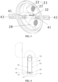
FIG. 1 is a schematic diagram of an earbud placed into an earbud case; -
FIG. 2 is a schematic diagram showing rightward movement of a rack; -
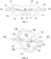
FIG. 3 is another schematic diagram showing rightward movement of a rack; -
FIG. 4 is another schematic diagram of an earbud placed into an earbud case; -
FIG. 5 is a schematic diagram showing leftward movement of a rack; -
FIG. 6 is another schematic diagram showing leftward movement of a rack; -
FIG. 7 is a schematic diagram of an earbud placed into an earbud case and in a charged state; -
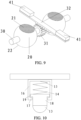
FIG. 8 is a schematic diagram of a movable part at a second position; -
FIG. 9 is a schematic diagram showing fitting between a gear and a rack; and -
FIG. 10 is a schematic diagram showing fitting between a conductive column and a connecting base. -
-
Earbud 100; -
housing 10;accommodation chamber 11;guide groove 12;conductive contact 13; - limiting
groove 14;elastic member 15; connectingbase 16; - limiting table 17;
conductive column 18;boss 19; -
movable part 20; firstconductive part 21; secondconductive part 22;first charging contact 23; - rotating
shaft 30;gear 31;rack 32; -
first magnet 41;second magnet 42;third magnet 43; -
earbud case 50;accommodation groove 51;second charging contact 52. - The technical solutions in embodiments of this application are clearly and completely described in the following with reference to the accompanying drawings in the embodiments of this application. Apparently, the described embodiments are merely some rather than all of the embodiments of this application. All other embodiments obtained by a person of ordinary skill in the art based on the embodiments of this application without making creative efforts shall fall within the protection scope of this application.
- The terms such as "first" and "second" in the description and claims of this application are intended to distinguish similar objects, but are not intended to describe a specific sequence or order. It should be understood that data used in such a way is interchangeable where appropriate so that the embodiments of this application can be implemented in an order other than those illustrated or described herein. In addition, "and/or" in the description and the claims indicates at least one of connected objects, and the character "/" generally indicates an "or" relationship between associated objects.
- With reference to
FIG. 1 to FIG. 10 , an earbud device according to an embodiment of this application is described in detail below through specific embodiments and application scenarios thereof. - As shown in
FIG. 1 to FIG. 10 , an earbud device according to the embodiment of this application may include: anearbud 100 and anearbud case 50. Theearbud 100 includes ahousing 10 and amovable part 20. Thehousing 10 is provided with anaccommodation chamber 11 with an opening, and themovable part 20 can move. Afirst charging contact 23 is arranged on themovable part 20, and themovable part 20 can be switched between a first position and a second position. Thefirst charging contact 23 avoids the opening of theaccommodation chamber 11 when themovable part 20 is at the first position, to prevent thefirst charging contact 23 from being in contact with an external environment, reduce corrosion by air or external moisture, and prevent stains or impurities from contaminating thefirst charging contact 23. When themovable part 20 is at the second position, thefirst charging contact 23 may be exposed at the opening of theaccommodation chamber 11, so that thefirst charging contact 23 may be electrically connected to a second charging contact in theearbud case 50, so as to charge theearbud 100. - The
earbud case 50 is provided with anaccommodation groove 51, and theearbud 100 may be placed into theaccommodation groove 51 or taken out from theaccommodation groove 51. Asecond charging contact 52 is provided in theaccommodation groove 51. A driving part is arranged in theearbud case 50, and the driving part can drive themovable part 20 to move from the first position to the second position during a process that theearbud 100 is placed into theaccommodation groove 51. The driving part can drive themovable part 20 to move from the second position to the first position during a process that theearbud 100 is taken out from theaccommodation groove 51. The driving part can drive themovable part 20 to be switched between the first position and the second position. The driving part may include a magnet, and themovable part 20 may be a member made of a magnetic material or a magnetic member may be provided on themovable part 20. Themovable part 20 can be switched between the first position and the second position by means of a magnetic force between the magnet and the magnetic member. The driving part may include an electro-deformable member, and when a current is input to the electro-deformable member, the electro-deformable member is deformed, and a deformation generated by the electro-deformable member can drive themovable part 20 to be switched between the first position and the second position. When theearbud 100 is placed into theaccommodation groove 51, thefirst charging contact 23 may be electrically connected to thesecond charging contact 52. Thesecond charging contact 52 may be a charging spring sheet, and thesecond charging contact 52 may be electrically connected to a second power supply part in theearbud case 50, so that theearbud 100 can be charged by the second power supply part. - During use, when the
movable part 20 is adjusted to the first position, thefirst charging contact 23 avoids the opening of theaccommodation chamber 11, so as to prevent thefirst charging contact 23 from being in contact with an external environment, reduce corrosion by air or external moisture, and prevent stains or impurities from contaminating thefirst charging contact 23, thereby preventing the stains or the impurities from contaminating the charging spring sheet in theearbud case 50 when theearbud 100 is placed into theearbud case 50, and avoiding damage to a charging circuit in theearbud case 50. When theearbud 100 is placed into theearbud case 50 for charging, themovable part 20 is adjusted to the second position, and thefirst charging contact 23 is exposed at the opening of theaccommodation chamber 11, so that thefirst charging contact 23 may be electrically connected to thesecond charging contact 52 in theearbud case 50, so as to charge theearbud 100. - In some embodiments, as shown in
FIG. 6 andFIG. 9 , the earbud device further includes: a transmission part. The transmission part may include: a rotatingshaft 30. Themovable part 20 may be arranged on therotating shaft 30, and therotating shaft 30 is rotatably arranged on thehousing 10. The driving part can drive the rotatingshaft 30 to rotate, and when the rotatingshaft 30 rotates, the rotatingshaft 30 drives themovable part 20 to be switched between the first position and the second position. The rotatingshaft 30 may be arranged in theaccommodation chamber 11, and an inner side wall of theaccommodation chamber 11 may be provided with rotating holes. Two ends of therotating shaft 30 may be arranged in the rotating holes, and the two ends of therotating shaft 30 can rotate in the rotating holes. The driving part can drive the rotatingshaft 30 to rotate, and the rotation of therotating shaft 30 can drive themovable part 20 to rotate, so that themovable part 20 can be switched between the first position and the second position, and therefore thefirst charging contact 23 can avoid the opening of theaccommodation chamber 11 or thefirst charging contact 23 is exposed at the opening of theaccommodation chamber 11. - In some other embodiments, as shown in
FIG. 1 to FIG. 9 , the transmission part may further include: agear 31 and arack 32. Thegear 31 may be sleeved on therotating shaft 30, and therack 32 meshes with thegear 31. The driving part can drive therack 32 to move, and therack 32 can drive thegear 31 to rotate during movement. Thegear 31 drives the rotatingshaft 30 to rotate, and the rotation of therotating shaft 30 can drive themovable part 20 to rotate, so that themovable part 20 can be switched between the first position and the second position. - In the embodiment of this application, as shown in
FIG. 1 to FIG. 9 , the transmission part may further include: afirst magnet 41. Thefirst magnet 41 is arranged on therack 32. One or morefirst magnets 41 may be provided, for example, twofirst magnets 41 may be provided, and thefirst magnets 41 may be arranged at two ends of therack 32. The driving part can drive thefirst magnet 41 to move, and thefirst magnet 41 can drive therack 32 to move during movement. The driving part may include asecond magnet 42. One or moresecond magnets 42 may be provided. Thefirst magnet 41 and thesecond magnet 42 can magnetically attract or repel each other. During the process that theearbud 100 is placed into theaccommodation groove 51, thesecond magnet 42 can drive thefirst magnet 41 to move in a first movement direction, and thefirst magnet 41 drives themovable part 20 to move from the first position to the second position. When thefirst magnet 41 and thesecond magnet 42 magnetically attract or repel each other, thesecond magnet 42 drives thefirst magnet 41 to move, and thefirst magnet 41 drives therack 32 to move. Thesecond magnet 42 may be a magnet arranged on theearbud case 50. During the process that theearbud 100 is placed into theaccommodation groove 51, thesecond magnet 42 can drive thefirst magnet 41 to move by means of magnetic action between thefirst magnet 41 and thesecond magnet 42, thefirst magnet 41 drives therack 32 to move, and therack 32 drives thegear 31 to rotate during movement. Thegear 31 drives the rotatingshaft 30 to rotate, and the rotation of therotating shaft 30 can drive themovable part 20 to rotate, so that themovable part 20 can move from the first position to the second position. - Optionally, as shown in
FIG. 1 to FIG. 4 , the driving part may include athird magnet 43. One or morethird magnets 43 may be provided. Thefirst magnet 41 and thethird magnet 43 can magnetically attract or repel each other. During the process that theearbud 100 is taken out from theaccommodation groove 51, thethird magnet 43 can drive thefirst magnet 41 to move in a second movement direction by means of a magnetic force between thefirst magnet 41 and thethird magnet 43, and thefirst magnet 41 drives themovable part 20 to move from the second position to the first position. The first movement direction is opposite to the second movement direction. During driving, thefirst magnet 41 drives therack 32 to move, and therack 32 drives thegear 31 to rotate during movement. Thegear 31 drives the rotatingshaft 30 to rotate, and the rotation of therotating shaft 30 can drive themovable part 20 to rotate, so that themovable part 20 can move from the second position to the first position. - In some embodiments, as shown in
FIG. 1 ,FIG. 4 , andFIG. 7 , during the process that theearbud 100 is placed into theaccommodation groove 51, thethird magnet 43 and thesecond magnet 42 may be sequentially disposed at an interval in a movement direction of theearbud 100. During the process that theearbud 100 is placed into theaccommodation groove 51, thesecond magnet 42 can drive thefirst magnet 41 to move, so that themovable part 20 can move from the first position to the second position. When themovable part 20 is at the second position, thefirst charging contact 23 is exposed at the opening of theaccommodation chamber 11, so that thefirst charging contact 23 may be electrically connected to thesecond charging contact 52 in theearbud case 50, so as to charge the earbud. During the process that the earbud is placed in or taken out, the position of themovable part 20 can be switched. During the process that theearbud 100 is taken out from theaccommodation groove 51, thethird magnet 43 can drive thefirst magnet 41 to move, and thefirst magnet 41 drives themovable part 20 to move from the second position to the first position. Thefirst charging contact 23 avoids the opening of theaccommodation chamber 11 when themovable part 20 is at the first position, to prevent thefirst charging contact 23 from being in contact with an external environment, reduce corrosion by air or external moisture, and prevent stains or impurities from contaminating thefirst charging contact 23. - Optionally, as shown in
FIG. 3 ,FIG. 5 ,FIG. 6 , andFIG. 8 , an inner side wall of theaccommodation chamber 11 may be provided with aguide groove 12, and therack 32 may be arranged in theguide groove 12. Two ends of therack 32 may be arranged in theguide groove 12, and the two ends of therack 32 can move in theguide groove 12. The movement of therack 32 can be guided through theguide groove 12, so that therack 32 can move stably. - In some embodiments, two
movable parts 20 may be provided, and the twomovable parts 20 may be disposed at an interval in a length direction of therotating shaft 30. Eachmovable part 20 may be spherical, and themovable part 20 may be provided with a through hole. Themovable part 20 may be sleeved on therotating shaft 30 through the through hole. Thegear 31 may be located between the twomovable parts 20, and the twomovable parts 20 may be symmetrically arranged with respect to thegear 31, such that the rotatingshaft 30 can stably drive themovable parts 20 to rotate, and therefore themovable parts 20 can be switched between the first position and the second position. - In some embodiments, as shown in
FIG. 3 ,FIG. 6 , andFIG. 9 , thefirst charging contact 23 may include a firstconductive part 21 and a secondconductive part 22 that are disposed at an interval, and the firstconductive part 21 is electrically connected to the secondconductive part 22. When themovable part 20 is at the first position, the firstconductive part 21 and the secondconductive part 22 avoid the opening of theaccommodation chamber 11. When themovable part 20 is at the second position, the firstconductive part 21 is exposed at the opening of theaccommodation chamber 11, and when theearbud 100 is placed into theaccommodation groove 51, the firstconductive part 21 is electrically connected to thesecond charging contact 52. - A first
conductive part 21 and a secondconductive part 22 that are disposed at an interval may be provided on themovable part 20. The firstconductive part 21 and the secondconductive part 22 may be oppositely arranged. The firstconductive part 21 may be arranged at one end or on one side of themovable part 20, and the secondconductive part 22 may be arranged at the other end or on the other side of themovable part 20. The firstconductive part 21 is electrically connected to the secondconductive part 22. Themovable part 20 may be cylindrical or spherical, or may be in other shapes according to an actual situation. The firstconductive part 21 and the secondconductive part 22 each may be a member made of a metal material. Themovable part 20 may be a conductive member with a surface coated with an insulation layer. Themovable part 20 may be a metal conductive member with a surface coated with an insulation layer. For example, themovable part 20 may be a copper conductive member with a surface coated with an insulation layer, and a corresponding surface area of the conductive member is coated with no insulation layer, so that a conductive portion of the conductive member is exposed, thereby forming a firstconductive part 21 and a secondconductive part 22. - The
movable part 20 can be switched between the first position and the second position. The firstconductive part 21 and the secondconductive part 22 avoid the opening of theaccommodation chamber 11 when themovable part 20 is at the first position, to prevent the firstconductive part 21 and the secondconductive part 22 from being in contact with an external environment, reduce corrosion by air or external moisture, and prevent stains or impurities from contaminating the firstconductive part 21 and the secondconductive part 22. The firstconductive part 21 is exposed at the opening of theaccommodation chamber 11 when themovable part 20 is at the second position. Theearbud 100 may be provided with a first power supply part. The secondconductive part 22 may be electrically connected to the first power supply part, the secondconductive part 22 may be electrically connected to aconductive contact 13 on the first power supply part, and the firstconductive part 21 may be electrically connected to thesecond charging contact 52 in theearbud case 50, so as to charge the earbud. - As shown in
FIG. 10 , a connectingbase 16 may be arranged on the first power supply part, and the connectingbase 16 may be provided with a limitinggroove 14. A limiting table 17 is arranged on an inner side wall of the limitinggroove 14. One end of aconductive column 18 extends into the limitinggroove 14, and aboss 19 is arranged at theconductive column 18 above the limiting table 17. Theboss 19 is arranged along a periphery of one end of theconductive column 18, and aconductive contact 13 is provided at the other end of theconductive column 18. Anelastic member 15 is arranged between an end portion of an end of theconductive column 18 and a bottom of the limitinggroove 14. Theelastic member 15 may be a member made of a conductive material, such as a metal member. Theelastic member 15 may be electrically connected to theconductive column 18, and theelastic member 15 may be a spring. An end of theconductive column 18 can move in the limitinggroove 14, and the moving range of theconductive column 18 can be limited by cooperation between the limiting table 17 and theboss 19. When themovable part 20 is at the second position, the secondconductive part 22 may be electrically connected to theconductive contact 13 on the first power supply part. In this case, theelastic member 15 may be in a compressed state, and the secondconductive part 22 can be stably connected to theconductive contact 13 through an elastic force of theelastic member 15. Theconductive contact 13 may be a spring sheet or a spring pin welded to a charging main board, and the spring sheet or the spring pin can telescopically move. - An elastic layer may be provided on the inner side wall of the
accommodation chamber 11 corresponding to the firstconductive part 21 and the secondconductive part 22. The firstconductive part 21 and the secondconductive part 22 avoid the opening of theaccommodation chamber 11 when themovable part 20 is at the first position. Surfaces of the firstconductive part 21 and the secondconductive part 22 may abut against and be in contact with the elastic layer, and the elastic layer may have a sealing effect. A small gap is provided between the surfaces of the firstconductive part 21 and the secondconductive part 22 and the elastic layer, which reduces contact between an external environment and the firstconductive part 21 and the secondconductive part 22, reduces corrosion by air or external moisture, and prevents stains or impurities from contaminating the firstconductive part 21 and the secondconductive part 22. Themovable part 20 can be switched between the first position and the second position, and the elastic layer can wipe off contaminants on the surfaces of the firstconductive part 21 and the secondconductive part 22 through the movable switching of themovable part 20. - In the earbud according to the embodiment of this application, the first
conductive part 21 and the secondconductive part 22 that are disposed at an interval are arranged on themovable part 20, and the positions of the firstconductive part 21 and the secondconductive part 22 can be adjusted by the movement of themovable part 20. The firstconductive part 21 and the secondconductive part 22 avoid the opening of theaccommodation chamber 11 when themovable part 20 is at the first position. The firstconductive part 21 is exposed at the opening of theaccommodation chamber 11 when themovable part 20 is at the second position, and the secondconductive part 22 is electrically connected to the first power supply part. During use, when themovable part 20 is adjusted to the first position, the firstconductive part 21 and the secondconductive part 22 avoid the opening of theaccommodation chamber 11, so as to prevent the firstconductive part 21 and the secondconductive part 22 from being in contact with an external environment, reduce corrosion by air or external moisture, and prevent stains or impurities from contaminating the firstconductive part 21 and the secondconductive part 22, thereby preventing the stains or the impurities from contaminating the charging spring sheet in theearbud case 50 when the earbud is placed into theearbud case 50, and avoiding damage to a charging circuit in theearbud case 50. When the earbud is placed into theearbud case 50 for charging, themovable part 20 is adjusted to the second position, the firstconductive part 21 is exposed at the opening of theaccommodation chamber 11, and the secondconductive part 22 is electrically connected to the first power supply part, so that the firstconductive part 21 may be electrically connected to the charging spring sheet in theearbud case 50, so as to charge the earbud. - Optionally, the
earbud 100 is provided with a first power supply part, and when themovable part 20 is at the second position, the secondconductive part 22 may be electrically connected to the first power supply part, so that the earbud can be charged. - In some embodiments, the earbud may further include: a
first magnet 41. Themovable part 20 may be connected to thefirst magnet 41. The driving part may include asecond magnet 42. One or moresecond magnets 42 may be provided. Thefirst magnet 41 and thesecond magnet 42 can magnetically attract or repel each other. During the process that the earbud is placed into theaccommodation groove 51, thesecond magnet 42 can drive thefirst magnet 41 to move in a first movement direction by means of magnetic action between thefirst magnet 41 and thesecond magnet 42, and thefirst magnet 41 drives themovable part 20 to move from the first position to the second position. - In some other embodiments, the driving part may include a
third magnet 43. One or morethird magnets 43 may be provided. Thefirst magnet 41 and thethird magnet 43 can magnetically attract or repel each other. During the process that the earbud is taken out from theaccommodation groove 51, thethird magnet 43 can drive thefirst magnet 41 to move in a second movement direction by means of a magnetic force between thefirst magnet 41 and thethird magnet 43, and thefirst magnet 41 drives themovable part 20 to move from the second position to the first position. The first movement direction is opposite to the second movement direction. - Optionally, during the process that the earbud is placed into the
accommodation groove 51, thethird magnet 43 and thesecond magnet 42 are sequentially disposed at an interval in a movement direction of the earbud. Themovable part 20 can move from the first position to the second position during the process that the earbud is placed into theaccommodation groove 51. Thefirst magnet 41 drives themovable part 20 to move from the second position to the first position during the process that the earbud is taken out from theaccommodation groove 51. During the process that the earbud is placed in or taken out, the position of themovable part 20 can be switched. - In some embodiments, the
third magnet 43 may be located above thesecond magnet 42. During the process that theearbud 100 is placed into theaccommodation groove 51, thefirst magnet 41 first approaches thethird magnet 43. When thefirst magnet 41 is approaching thethird magnet 43, thethird magnet 43 can drive thefirst magnet 41 to move, thefirst magnet 41 can drive therack 32 to move in the second movement direction, and therack 32 drives themovable part 20 to be at the first position. When the earbud continues to move to a bottom of theaccommodation groove 51, thefirst magnet 41 moves away from thethird magnet 43, and thefirst magnet 41 approaches thesecond magnet 42. Thesecond magnet 42 can drive thefirst magnet 41 to move, thefirst magnet 41 can drive therack 32 to move in the first movement direction, and when therack 32 drives themovable part 20 to be at the second position, the firstconductive part 21 may be electrically connected to thesecond charging contact 52 in theearbud case 50, so as to charge the earbud. - During the process that the earbud is taken out from the
accommodation groove 51, thefirst magnet 41 gradually moves away from thesecond magnet 42, and thefirst magnet 41 gradually approaches thethird magnet 43. When thefirst magnet 41 is approaching thethird magnet 43, thethird magnet 43 drives thefirst magnet 41 to move, thefirst magnet 41 drives therack 32 to move in the second movement direction, and when therack 32 drives themovable part 20 to be at the first position, the firstconductive part 21 and the secondconductive part 22 avoid the opening of theaccommodation chamber 11, to prevent the firstconductive part 21 and the secondconductive part 22 from being in contact with an external environment, reduce corrosion by air or external moisture, and prevent stains or impurities from contaminating the firstconductive part 21 and the secondconductive part 22. - As shown in
FIG. 2 andFIG. 3 ,first magnets 41 may be arranged at two ends of therack 32 respectively, andthird magnets 43 may be arranged on theearbud case 50 corresponding to thefirst magnets 41. Thefirst magnet 41 at the left end of therack 32 and thethird magnet 43 on a left side of the rack repel each other, and thefirst magnet 41 at the right end of therack 32 and thethird magnet 43 on a right side of the rack attract each other, so that therack 32 moves rightward. Therack 32 drives thegear 31 to rotate, and thegear 31 drives the rotatingshaft 30 to rotate. The rotation of therotating shaft 30 can drive themovable part 20 to rotate, so that themovable part 20 can be at the first position. When themovable part 20 is at the first position, the firstconductive part 21 and the secondconductive part 22 avoid the opening of theaccommodation chamber 11, so as to prevent the firstconductive part 21 and the secondconductive part 22 from being in contact with an external environment, reduce corrosion by air or external moisture, and prevent stains or impurities from contaminating the firstconductive part 21 and the secondconductive part 22, thereby preventing the stains or the impurities from contaminating the charging spring sheet in theearbud case 50 when the earbud is placed into theearbud case 50, and avoiding damage to the charging circuit in theearbud case 50. - As shown in
FIG. 5 and FIG. 6 ,first magnets 41 may be arranged at two ends of therack 32 respectively, andsecond magnets 42 may be arranged on theearbud case 50 corresponding to thefirst magnets 41. Thefirst magnet 41 at the left end of therack 32 and thesecond magnet 42 on a left side of the rack attract each other, and thefirst magnet 41 at the right end of therack 32 and thesecond magnet 42 on a right side of the rack repel each other, so that therack 32 moves leftward. Therack 32 drives thegear 31 to rotate, and thegear 31 drives the rotatingshaft 30 to rotate. The rotation of therotating shaft 30 can drive themovable part 20 to rotate, so that themovable part 20 can be at the second position, the firstconductive part 21 can be exposed at the opening of theaccommodation chamber 11, and the secondconductive part 22 may be electrically connected to the first power supply part. Therefore, the firstconductive part 21 may be electrically connected to the charging spring sheet in theearbud case 50, so as to charge the earbud. - The embodiments of this application are described above with reference to the accompanying drawings, but this application is not limited to the specific implementations described above, and the specific implementations described above are merely illustrative and not restrictive. A person of ordinary skill in the art may further make many forms under the teaching of this application without departing from the purpose of this application and the protection scope of the claims, and these forms all fall within the protection scope of this application.
Claims (12)
- An earbud device, comprising:an earbud, wherein the earbud comprises a housing and a movable part, the housing is provided with an accommodation chamber with an opening, a first charging contact is arranged on the movable part, the first charging contact avoids the opening of the accommodation chamber when the movable part is at a first position, and the first charging contact is exposed at the opening of the accommodation chamber when the movable part is at a second position; andan earbud case, wherein the earbud case is provided with an accommodation groove, a second charging contact is arranged in the accommodation groove, a driving part is arranged in the earbud case, the driving part drives the movable part to move from the first position to the second position during a process that the earbud is placed into the accommodation groove, and the driving part drives the movable part to move from the second position to the first position during a process that the earbud is taken out from the accommodation groove, whereinwhen the earbud is placed into the accommodation groove, the first charging contact is electrically connected to the second charging contact.
- The earbud device according to claim 1, further comprising:
a transmission part, wherein the transmission part comprises:
a rotating shaft, wherein the movable part is arranged on the rotating shaft, the rotating shaft is rotatably arranged on the housing, the driving part is capable of driving the rotating shaft to rotate, and when the rotating shaft rotates, the rotating shaft drives the movable part to move between the first position and the second position. - The earbud device according to claim 2, wherein the transmission part further comprises:a gear, wherein the gear is sleeved on the rotating shaft; anda rack, wherein the rack meshes with the gear, the driving part is capable of driving the rack to move, the rack drives the gear to rotate during movement, and the gear drives the rotating shaft to rotate.
- The earbud device according to claim 3, wherein the transmission part further comprises:a first magnet, wherein the first magnet is arranged on the rack, the driving part is capable of driving the first magnet to move, and the first magnet drives the rack to move;the driving part comprises a second magnet, and the first magnet and the second magnet are capable of magnetically attracting or repelling each other; andduring a process that the earbud is placed into the accommodation groove, the second magnet drives the first magnet to move in a first movement direction, and the first magnet drives the movable part to move from the first position to the second position.
- The earbud device according to claim 4, wherein the driving part comprises a third magnet, and the first magnet and the third magnet are capable of magnetically attracting or repelling each other; and
during a process that the earbud is taken out from the accommodation groove, the third magnet drives the first magnet to move in a second movement direction, the first magnet drives the movable part to move from the second position to the first position, and the first movement direction is opposite to the second movement direction. - The earbud device according to claim 5, wherein during a process that the earbud is placed into the accommodation groove, the third magnet and the second magnet are sequentially disposed at an interval along a movement direction of the earbud.
- The earbud device according to claim 3, wherein an inner side wall of the accommodation chamber is provided with a guide groove, and the rack is arranged in the guide groove.
- The earbud device according to claim 1, whereinthe first charging contact comprises a first conductive part and a second conductive part that are disposed at an interval, and the first conductive part is electrically connected to the second conductive part;when the movable part is at the first position, the first conductive part and the second conductive part avoid the opening of the accommodation chamber; andwhen the movable part is at the second position, the first conductive part is exposed at the opening of the accommodation chamber, and when the earbud is placed into the accommodation groove, the first conductive part is electrically connected to the second charging contact.
- The earbud device according to claim 8, wherein the earbud is provided with a first power supply part, and when the movable part is at the second position, the second conductive part is electrically connected to the first power supply part.
- The earbud device according to claim 1, wherein the earbud further comprises:a first magnet, wherein the movable part is connected to the first magnet, the driving part comprises a second magnet, and the first magnet and the second magnet are capable of magnetically attracting or repelling each other; andduring the process that the earbud is placed into the accommodation groove, the second magnet drives the first magnet to move in a first movement direction, and the first magnet drives the movable part to move from the first position to the second position.
- The earbud device according to claim 10, wherein the driving part comprises a third magnet, and the first magnet and the third magnet are capable of magnetically attracting or repelling each other; and
during a process that the earbud is taken out from the accommodation groove, the third magnet drives the first magnet to move in a second movement direction, the first magnet drives the movable part to move from the second position to the first position, and the first movement direction is opposite to the second movement direction. - The earbud device according to claim 11, wherein during a process that the earbud is placed into the accommodation groove, the third magnet and the second magnet are sequentially disposed at an interval in a movement direction of the earbud.
Applications Claiming Priority (2)
| Application Number | Priority Date | Filing Date | Title |
|---|---|---|---|
| CN202210625527.8A CN114845202B (en) | 2022-06-02 | 2022-06-02 | Headphones |
| PCT/CN2023/096471 WO2023231909A1 (en) | 2022-06-02 | 2023-05-26 | Earbud device |
Publications (2)
| Publication Number | Publication Date |
|---|---|
| EP4535820A1 true EP4535820A1 (en) | 2025-04-09 |
| EP4535820A4 EP4535820A4 (en) | 2026-04-22 |
Family
ID=82573388
Family Applications (1)
| Application Number | Title | Priority Date | Filing Date |
|---|---|---|---|
| EP23815092.4A Pending EP4535820A4 (en) | 2022-06-02 | 2023-05-26 | EARPHONE DEVICE |
Country Status (4)
| Country | Link |
|---|---|
| US (1) | US20250097620A1 (en) |
| EP (1) | EP4535820A4 (en) |
| CN (1) | CN114845202B (en) |
| WO (1) | WO2023231909A1 (en) |
Families Citing this family (4)
| Publication number | Priority date | Publication date | Assignee | Title |
|---|---|---|---|---|
| CN114845202B (en) * | 2022-06-02 | 2025-01-14 | 维沃移动通信有限公司 | Headphones |
| CN115458995B (en) * | 2022-10-08 | 2025-05-06 | 浙江地芯引力科技有限公司 | Electrical connector |
| CN115914923A (en) * | 2022-11-24 | 2023-04-04 | 歌尔科技有限公司 | Headphone Cases and Headphone Kits |
| CN116962927B (en) * | 2023-05-16 | 2025-10-31 | 深圳市亿道数码技术有限公司 | Earphone storage structure and notebook computer |
Family Cites Families (9)
| Publication number | Priority date | Publication date | Assignee | Title |
|---|---|---|---|---|
| JP3794363B2 (en) * | 2002-09-13 | 2006-07-05 | ソニー株式会社 | Charging apparatus and charging method |
| US9398365B2 (en) * | 2013-03-22 | 2016-07-19 | Otter Products, Llc | Earphone assembly |
| CN213462208U (en) * | 2020-10-29 | 2021-06-15 | 歌尔科技有限公司 | Earphone charging box |
| CN213846991U (en) * | 2021-01-27 | 2021-07-30 | 维沃移动通信有限公司 | earphone |
| CN113840204A (en) * | 2021-09-24 | 2021-12-24 | 维沃移动通信有限公司 | Wireless Headphones, Charging Cases, and Wireless Headphone Devices |
| CN113840203B (en) * | 2021-09-24 | 2024-08-16 | 维沃移动通信有限公司 | Wireless earphone, charging box and wireless earphone equipment |
| CN114143654B (en) * | 2021-12-06 | 2024-08-13 | 维沃移动通信有限公司 | Wireless headphones, headphone boxes and wireless headphone equipment |
| CN114339528B (en) * | 2022-01-06 | 2024-11-15 | 维沃移动通信有限公司 | Charging equipment, electronic devices and electronic device components |
| CN114845202B (en) * | 2022-06-02 | 2025-01-14 | 维沃移动通信有限公司 | Headphones |
-
2022
- 2022-06-02 CN CN202210625527.8A patent/CN114845202B/en active Active
-
2023
- 2023-05-26 WO PCT/CN2023/096471 patent/WO2023231909A1/en not_active Ceased
- 2023-05-26 EP EP23815092.4A patent/EP4535820A4/en active Pending
-
2024
- 2024-12-02 US US18/965,596 patent/US20250097620A1/en active Pending
Also Published As
| Publication number | Publication date |
|---|---|
| WO2023231909A1 (en) | 2023-12-07 |
| US20250097620A1 (en) | 2025-03-20 |
| EP4535820A4 (en) | 2026-04-22 |
| CN114845202B (en) | 2025-01-14 |
| CN114845202A (en) | 2022-08-02 |
Similar Documents
| Publication | Publication Date | Title |
|---|---|---|
| EP4535820A1 (en) | Earbud device | |
| US9101052B2 (en) | Sliding mechanism and electronic apparatus having same | |
| US11381725B2 (en) | Electronic devices and method for controlling camera module | |
| US10841475B2 (en) | Camera assembly and electronic device | |
| JP5171365B2 (en) | Plug connector | |
| CN106992099B (en) | Contactor device | |
| CN207381337U (en) | Improved relay | |
| CN111526272A (en) | Electronic device | |
| CN107507739A (en) | A sealed contact assembly | |
| WO2021227503A1 (en) | Card holder assembly, and mobile terminal comprising same | |
| CN213936053U (en) | Bistable switching device | |
| CN110299263B (en) | Micro switch | |
| CN219350087U (en) | Magnetic latching thermosensitive switch | |
| CN114709096B (en) | Micro-switch | |
| CN216412974U (en) | Relay | |
| CN109920695A (en) | Permanent magnetic drive type vacuum switch | |
| JP2019212705A (en) | Magnetic attraction device | |
| CN208045340U (en) | A kind of fast magnetic force operating mechanism for mechanical switch | |
| TWI915122B (en) | Stylus, electronic device and electronic system | |
| CN115039525B (en) | Axis drive device and component mounting device | |
| CN113745875A (en) | Wearable device and wearable device assembly | |
| CN218525535U (en) | Circuit breaker | |
| CN114055445B (en) | Cantilever structure and assembly device | |
| CN222394739U (en) | Disconnector | |
| CN222734897U (en) | An AC/DC relay |
Legal Events
| Date | Code | Title | Description |
|---|---|---|---|
| STAA | Information on the status of an ep patent application or granted ep patent |
Free format text: STATUS: THE INTERNATIONAL PUBLICATION HAS BEEN MADE |
|
| PUAI | Public reference made under article 153(3) epc to a published international application that has entered the european phase |
Free format text: ORIGINAL CODE: 0009012 |
|
| STAA | Information on the status of an ep patent application or granted ep patent |
Free format text: STATUS: REQUEST FOR EXAMINATION WAS MADE |
|
| 17P | Request for examination filed |
Effective date: 20241204 |
|
| AK | Designated contracting states |
Kind code of ref document: A1 Designated state(s): AL AT BE BG CH CY CZ DE DK EE ES FI FR GB GR HR HU IE IS IT LI LT LU LV MC ME MK MT NL NO PL PT RO RS SE SI SK SM TR |
|
| DAV | Request for validation of the european patent (deleted) | ||
| DAX | Request for extension of the european patent (deleted) | ||
| REG | Reference to a national code |
Ref country code: DE Ref legal event code: R079 Free format text: PREVIOUS MAIN CLASS: H04R0001100000 Ipc: H02J0007700000 |
|
| A4 | Supplementary search report drawn up and despatched |
Effective date: 20260323 |
|
| RIC1 | Information provided on ipc code assigned before grant |
Ipc: H02J 7/70 20260101AFI20260317BHEP Ipc: H04R 1/10 20060101ALI20260317BHEP Ipc: H04R 1/1025 20260101ALI20260317BHEP |