EP4535700A2 - Dynamische verarbeitungszeit und dynamische blinddecodierungsfähigkeit für nr-benutzervorrichtungen - Google Patents
Dynamische verarbeitungszeit und dynamische blinddecodierungsfähigkeit für nr-benutzervorrichtungen Download PDFInfo
- Publication number
- EP4535700A2 EP4535700A2 EP24219456.1A EP24219456A EP4535700A2 EP 4535700 A2 EP4535700 A2 EP 4535700A2 EP 24219456 A EP24219456 A EP 24219456A EP 4535700 A2 EP4535700 A2 EP 4535700A2
- Authority
- EP
- European Patent Office
- Prior art keywords
- processing time
- processing
- base station
- wireless communication
- criteria
- Prior art date
- Legal status (The legal status is an assumption and is not a legal conclusion. Google has not performed a legal analysis and makes no representation as to the accuracy of the status listed.)
- Pending
Links
Images


Classifications
-
- H—ELECTRICITY
- H04—ELECTRIC COMMUNICATION TECHNIQUE
- H04W—WIRELESS COMMUNICATION NETWORKS
- H04W24/00—Supervisory, monitoring or testing arrangements
- H04W24/02—Arrangements for optimising operational condition
-
- H—ELECTRICITY
- H04—ELECTRIC COMMUNICATION TECHNIQUE
- H04W—WIRELESS COMMUNICATION NETWORKS
- H04W76/00—Connection management
-
- H—ELECTRICITY
- H04—ELECTRIC COMMUNICATION TECHNIQUE
- H04L—TRANSMISSION OF DIGITAL INFORMATION, e.g. TELEGRAPHIC COMMUNICATION
- H04L1/00—Arrangements for detecting or preventing errors in the information received
- H04L1/0001—Systems modifying transmission characteristics according to link quality, e.g. power backoff
- H04L1/0036—Systems modifying transmission characteristics according to link quality, e.g. power backoff arrangements specific to the receiver
- H04L1/0038—Blind format detection
-
- H—ELECTRICITY
- H04—ELECTRIC COMMUNICATION TECHNIQUE
- H04L—TRANSMISSION OF DIGITAL INFORMATION, e.g. TELEGRAPHIC COMMUNICATION
- H04L1/00—Arrangements for detecting or preventing errors in the information received
- H04L1/12—Arrangements for detecting or preventing errors in the information received by using return channel
- H04L1/16—Arrangements for detecting or preventing errors in the information received by using return channel in which the return channel carries supervisory signals, e.g. repetition request signals
- H04L1/18—Automatic repetition systems, e.g. Van Duuren systems
- H04L1/1812—Hybrid protocols; Hybrid automatic repeat request [HARQ]
-
- H—ELECTRICITY
- H04—ELECTRIC COMMUNICATION TECHNIQUE
- H04L—TRANSMISSION OF DIGITAL INFORMATION, e.g. TELEGRAPHIC COMMUNICATION
- H04L1/00—Arrangements for detecting or preventing errors in the information received
- H04L1/12—Arrangements for detecting or preventing errors in the information received by using return channel
- H04L1/16—Arrangements for detecting or preventing errors in the information received by using return channel in which the return channel carries supervisory signals, e.g. repetition request signals
- H04L1/18—Automatic repetition systems, e.g. Van Duuren systems
- H04L1/1829—Arrangements specially adapted for the receiver end
- H04L1/1854—Scheduling and prioritising arrangements
-
- H—ELECTRICITY
- H04—ELECTRIC COMMUNICATION TECHNIQUE
- H04L—TRANSMISSION OF DIGITAL INFORMATION, e.g. TELEGRAPHIC COMMUNICATION
- H04L1/00—Arrangements for detecting or preventing errors in the information received
- H04L1/12—Arrangements for detecting or preventing errors in the information received by using return channel
- H04L1/16—Arrangements for detecting or preventing errors in the information received by using return channel in which the return channel carries supervisory signals, e.g. repetition request signals
- H04L1/18—Automatic repetition systems, e.g. Van Duuren systems
- H04L1/1829—Arrangements specially adapted for the receiver end
- H04L1/1858—Transmission or retransmission of more than one copy of acknowledgement message
-
- H—ELECTRICITY
- H04—ELECTRIC COMMUNICATION TECHNIQUE
- H04L—TRANSMISSION OF DIGITAL INFORMATION, e.g. TELEGRAPHIC COMMUNICATION
- H04L5/00—Arrangements affording multiple use of the transmission path
- H04L5/003—Arrangements for allocating sub-channels of the transmission path
- H04L5/0044—Allocation of payload; Allocation of data channels, e.g. PDSCH or PUSCH
-
- H—ELECTRICITY
- H04—ELECTRIC COMMUNICATION TECHNIQUE
- H04L—TRANSMISSION OF DIGITAL INFORMATION, e.g. TELEGRAPHIC COMMUNICATION
- H04L5/00—Arrangements affording multiple use of the transmission path
- H04L5/003—Arrangements for allocating sub-channels of the transmission path
- H04L5/0053—Allocation of signalling, i.e. of overhead other than pilot signals
-
- H—ELECTRICITY
- H04—ELECTRIC COMMUNICATION TECHNIQUE
- H04L—TRANSMISSION OF DIGITAL INFORMATION, e.g. TELEGRAPHIC COMMUNICATION
- H04L5/00—Arrangements affording multiple use of the transmission path
- H04L5/003—Arrangements for allocating sub-channels of the transmission path
- H04L5/0078—Timing of allocation
-
- H—ELECTRICITY
- H04—ELECTRIC COMMUNICATION TECHNIQUE
- H04L—TRANSMISSION OF DIGITAL INFORMATION, e.g. TELEGRAPHIC COMMUNICATION
- H04L5/00—Arrangements affording multiple use of the transmission path
- H04L5/0091—Signalling for the administration of the divided path, e.g. signalling of configuration information
- H04L5/0094—Indication of how sub-channels of the path are allocated
-
- H—ELECTRICITY
- H04—ELECTRIC COMMUNICATION TECHNIQUE
- H04W—WIRELESS COMMUNICATION NETWORKS
- H04W8/00—Network data management
- H04W8/22—Processing or transfer of terminal data, e.g. status or physical capabilities
- H04W8/24—Transfer of terminal data
-
- H—ELECTRICITY
- H04—ELECTRIC COMMUNICATION TECHNIQUE
- H04W—WIRELESS COMMUNICATION NETWORKS
- H04W88/00—Devices specially adapted for wireless communication networks, e.g. terminals, base stations or access point devices
- H04W88/02—Terminal devices
-
- Y—GENERAL TAGGING OF NEW TECHNOLOGICAL DEVELOPMENTS; GENERAL TAGGING OF CROSS-SECTIONAL TECHNOLOGIES SPANNING OVER SEVERAL SECTIONS OF THE IPC; TECHNICAL SUBJECTS COVERED BY FORMER USPC CROSS-REFERENCE ART COLLECTIONS [XRACs] AND DIGESTS
- Y02—TECHNOLOGIES OR APPLICATIONS FOR MITIGATION OR ADAPTATION AGAINST CLIMATE CHANGE
- Y02D—CLIMATE CHANGE MITIGATION TECHNOLOGIES IN INFORMATION AND COMMUNICATION TECHNOLOGIES [ICT], I.E. INFORMATION AND COMMUNICATION TECHNOLOGIES AIMING AT THE REDUCTION OF THEIR OWN ENERGY USE
- Y02D30/00—Reducing energy consumption in communication networks
- Y02D30/70—Reducing energy consumption in communication networks in wireless communication networks
Definitions
- the present application relates to the field of wireless communication systems or networks, more specifically to enhancements or improvements regarding the processing time or the blind decoding capability for NR user devices, UEs.
- Embodiments of the present invention concern dynamic processing times for NR UEs, like NR Light UEs, or low-complexity devices, or power saving UEs. Further embodiments of the present invention concern a dynamic blind decoding capability for NR UEs, like NR Light UEs, low-complexity devices, or power saving UEs.
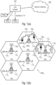
- Fig. 1 is a schematic representation of an example of a terrestrial wireless network 100 including, as is shown in Fig. 1(a) , a core network 102 and one or more radio access networks RAN 1 , RAN 2 , ... RAN N .
- Fig. 1(b) is a schematic representation of an example of a radio access network RAN n that may include one or more base stations gNB 1 to gNB 5 , each serving a specific area surrounding the base station schematically represented by respective cells 106 1 to 106 5 .
- the base stations are provided to serve users within a cell.
- the one or more base stations may serve users in licensed and/or unlicensed bands.
- base station refers to a gNB in 5G networks, an eNB in UMTS/LTE/LTE-A/ LTE-A Pro, or just a BS in other mobile communication standards.
- a user may be a stationary device or a mobile device.
- the wireless communication system may also be accessed by mobile or stationary loT devices which connect to a base station or to a user.
- the mobile devices or the loT devices may include physical devices, ground based vehicles, such as robots or cars, aerial vehicles, such as manned or unmanned aerial vehicles (UAVs), the latter also referred to as drones, buildings and other items or devices having embedded therein electronics, software, sensors, actuators, or the like as well as network connectivity that enables these devices to collect and exchange data across an existing network infrastructure.
- Fig. 1(b) shows an exemplary view of five cells, however, the RAN n may include more or less such cells, and RAN n may also include only one base station.
- Fig. 1(b) shows two users UE 1 and UE 2 , also referred to as user equipment, UE, that are in cell 106 2 and that are served by base station gNB 2 .
- the loT device 110 accesses the wireless communication system via the base station gNB 4 to receive and transmit data as schematically represented by arrow 112 1 .
- the loT device 110 2 accesses the wireless communication system via the user UE 3 as is schematically represented by arrow 112 2 .
- the respective base station gNB 1 to gNB 5 may be connected to the core network 102, e.g. via the S1 interface, via respective backhaul links 114 1 to 114 5 , which are schematically represented in Fig. 1(b) by the arrows pointing to "core".
- the core network 102 may be connected to one or more external networks. Further, some or all of the respective base station gNB 1 to gNB 5 may be connected, e.g.
- a sidelink channel allows direct communication between UEs, also referred to as device-to-device (D2D) communication.
- D2D device-to-device
- the sidelink interface in 3GPP is named PC5.
- the physical resource grid may comprise a set of resource elements to which various physical channels and physical signals are mapped.
- the physical channels may include the physical downlink, uplink and sidelink shared channels (PDSCH, PUSCH, PSSCH) carrying user specific data, also referred to as downlink, uplink and sidelink payload data, the physical broadcast channel (PBCH) carrying for example a master information block (MIB) and one or more of a system information block (SIB), the physical downlink, uplink and sidelink control channels (PDCCH, PUCCH, PSSCH) carrying for example the downlink control information (DCI), the uplink control information (UCI) and the sidelink control information (SCI).
- the sidelink interface may a support 2-stage SCI. This refers to a first control region containing some parts of the SCI, and optionally, a second control region, which contains a second part of control information.
- the physical channels may further include the physical random access channel (PRACH or RACH) used by UEs for accessing the network once a UE synchronized and obtained the MIB and SIB.
- the physical signals may comprise reference signals or symbols (RS), synchronization signals and the like.
- the resource grid may comprise a frame or radio frame having a certain duration in the time domain and having a given bandwidth in the frequency domain.
- the frame may have a certain number of subframes of a predefined length, e.g. 1ms. Each subframe may include one or more slots of 12 or 14 OFDM symbols depending on the cyclic prefix (CP) length.
- a frame may also consist of a smaller number of OFDM symbols, e.g. when utilizing shortened transmission time intervals (sTTI) or a mini-slot/non-slot-based frame structure comprising just a few OFDM symbols.
- sTTI shortened transmission time intervals
- mini-slot/non-slot-based frame structure comprising just
- the wireless network or communication system depicted in Fig. 1 may be a heterogeneous network having distinct overlaid networks, e.g., a network of macro cells with each macro cell including a macro base station, like base station gNB 1 to gNB 5 , and a network of small cell base stations (not shown in Fig. 1 ), like femto or pico base stations.
- a network of macro cells with each macro cell including a macro base station, like base station gNB 1 to gNB 5 , and a network of small cell base stations (not shown in Fig. 1 ), like femto or pico base stations.
- the UE is to activate the processing time switching responsive to a signaling, e.g., an RRC or MAC CE or a DCI, from the wireless communication system, e.g., from the base station.
- a signaling e.g., an RRC or MAC CE or a DCI
- the base station is to receive from the UE, e.g., when the connects or reconnects to the wireless communication system, a signaling of its capability to switch processing times.
- the present invention provides (see for example claim 30) a method for operating a wireless communication system, the wireless communication system comprising one or more user devices, UEs, the method comprising:
- the present invention provides (see for example claim 31) a method for operating a wireless communication system, the wireless communication system comprising one or more user devices, UEs, and one or more base stations, the method comprising:
- the present invention provides (see for example claim 18) a user device, UE, for a wireless communication system,
- the UE is to determine
- the UE is to receive, e.g., using an RRC signaling in response to signaling the UE capability to the wireless communication system,
- the search space configuration indicates
- the UE responsive to receiving the control message and setting the number of maximum blind decodings according to the minimum time signaled in the control message, the UE is to apply the determined number of maximum blind decodings or the determined set of search spaces after a certain application delay.
- Embodiments of the present invention provide a computer program product comprising instructions which, when the program is executed by a computer, causes the computer to carry out one or more methods in accordance with the present invention.
- Fig. 3 schematically illustrates a user device, UE, in accordance with embodiments of the first aspect of the present invention.
- the UE comprises an antenna ANT for receiving from a source a transmission or for transmitting a transmission towards a target, like a gNB.
- the UE may process a transmission received at the UE or to be prepared by the UE within a first transmitting time T1 and, responsive to one or more criteria, the UE may switch from the first processing time T1 to a second processing time T2 to be used to process the transmission received at the UE or to be prepared by the UE.
- the UE may include a processor P for processing the transmission.
- a storage M may be provided to store processing times that the UE may employ and among which the UE may switch.
- Fig. 4 schematically illustrates a base station, like a gNB, in accordance with embodiments of the first aspect of the present invention that is to serve a UE capable of switching its processing times, for example, a UE as described above with reference to Fig. 3 .
- the gNB for example, once being informed by the UE about its capability to switch processing times, may activate the processing time switching at the UE by sending a corresponding signaling to the UE, e.g., using RRC or MAC Control Element, MAC CE, or DCI message, or a combination thereof.
- a dynamic switching of processing times is implemented.
- a first processing time may be employed that is particularly suitable for these devices and the capabilities the devices have.
- This first processing time may also be referred to as a more relaxed processing time, which is a processing time that is longer than a second processing time that may be used for devices having higher processing capabilities, like higher hardware capabilities, allowing the implementation of shorter processing times.
- an acknowledgement may be transmitted for the transmission in PDSCH4 already in PUCCH1 that is indicated by the HARQ-timing-indicator, i.e., ahead of the relaxed processing time T1.
- a non-acknowledgement may be transmitted for the transmission in PDSCH4 in PUCCH1.
- PDSCH2 and PDSCH3 an ACK or a NACK may be transmitted in PUCCH1.
- the feedback is indicated in Fig. 6 at FB1 as A/N, A/N, A/N, A/N - meaning that for PDSCH1 to PDSCH4 an ACK or a NACK is transmitted.
- the initial or default processing time T1 is maintained, i.e., the longer, relaxed processing time, i.e., the processing of the transmission of PDSCH4 is completed only after the scheduled PUCCH1.
- the transmission in PDSCH4 may be considered not successful, and, while for the transmissions in PDSCH1, PDSCH2 and PDSCH3 an ACK or a NACK may be transmitted in PUCCH1, for PDSCH4 a NACK is transmitted, or the UE may drop the feedback for PDSCH4.
- the feedback is indicated Fig.
- the UE may not report include a HARQ feedback for PDSCH4 in PUCCH1.
- the one or more criteria on the basis of which the UE decides to switch between the processing times T1 and T2, may include one or more of the following:
- Fig. 7 illustrates embodiments of the dynamic switching in a HARQ-scenario dependent on the above-mentioned criteria.
- Fig. 7(a) describes an embodiment of the dynamic switching in a HARQ-scenario when a number of transmissions received in a certain time window before the scheduled transmission is at or below a certain threshold.
- a UE may receive the downlink transmissions PDSCH#0 in slot#0, PDSCH#1 in slot#1, PDSCH#2 in slot#2 and PDSCH#3 in slot#3.
- a HARQ-timing indicator indicates a PUCCH in slot#5 for an uplink transmission of an HARQ-ACK.
- the certain time window before the transmission PDSCH3 which is currently processed in slot#3 comprises three slots, slot#0 to slot#2, and the certain threshold is assumed to be a maximum of less than one PDSCH in each of the previous slot#0 to slot#2.
- Fig. 7(b) describes an embodiment of the dynamic switching in a HARQ-scenario when a number of transmissions that the UE supports in a certain time window after the scheduled transmission is at or below a certain threshold.
- a UE may receive the downlink transmissions PDSCH#0 in slot#0, PDSCH#1 in slot#1, PDSCH#2 in slot#2, PDSCH#3 in slot#3 and PDSCH#4 in slot#4.
- a HARQ-timing indicator indicates a PUCCH in slot#5 for an uplink transmission of an HARQ-ACK.
- the certain time window after the transmission PDSCH#3 which is currently processed in slot#3 comprises one slot, slot#4, and the certain threshold is assumed to be zero PDSCHs in the next slot.
- the HARQ feedback transmitted in the PUCCH incudes only the feedback for PDSCH#0 to PDSCH#2 as indicated by FB2.
- the dynamic switching in a HARQ-scenario may occur dependent on certain position of a HARQ feedback for one of a plurality of transmissions in a HARQ-ACK codebook.
- the HARQ-ACK feedback indicates that the feedback FB1 or FB2 for the transmissions or receptions PDSCH1 to PDSCH4 are transmitted in PUCCH1.
- the UE may switch to the stringent processing time T2 for processing the transmission PDSCH4, the last transmission for which HARQ feedback in the HARQ-ACK codebook is to be reported in PUCCH1.
- the dynamic switching in a HARQ-scenario may occur dependent on a size of one or more of a current transmission, a previous transmission, a following transmission.
- the size may be the Transport Block Size, TBS, the Bandwidth in PRBs, the duration of the transmission, e.g., a Slot Aggregation Factor or number of OFDM symbols within a slot, or a number of resource elements, RE, or a number of Code Block Groups, CBGs.
- TBS Transport Block Size
- the Bandwidth in PRBs the duration of the transmission, e.g., a Slot Aggregation Factor or number of OFDM symbols within a slot, or a number of resource elements, RE, or a number of Code Block Groups, CBGs.
- the reception may be completed earlier than for a longer transmission and the UE may start the processing earlier and complete the processing, e.g., before a next transmission is received.
- the processing steps e.g. demodulation or decoding, may finish earlier for smaller transmissions since a lesser number of computational steps are required.
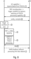
- Fig. 8 illustrates an embodiment in which the UE is preconfigured by the network to switch to a different PDSCH processing time.
- the UE initially signals 1 its capability of switching the processing times. For example, the UE may signal this when connecting or reconnecting to the network via the gNB.
- An example of a UE capability IE syntax for dynamic PDSCH processing time may be as follows:
- the gNB may configure 2 the UE with the dynamic processing time switching, e.g., the processing time switching functionality may be activated by the gNB, e.g., using an RRC reconfiguration message.
- the one or more criteria to be met for a switching to one of two or more processing times are also included in the message.
- One of the processing times may be considered the default time, for which no constraints apply, and the gNB includes the one or more criteria to be met for allowing a switching to the second, shorter processing time or, in accordance with other embodiments, to one of a plurality of shorter processing times selected dependent on certain criteria associated with the respective different shorter processing times.
- the network does not configure the UE with a more relaxed criteria than a default criteria that may be signaled by the UE.
- the gNB when configuring the UE by the network, may signal at 2 one, some or all of the available criteria associated with one or more of the possible processing times that may be employed by the UE.
- the UE may be preconfigured with a processing-switching-time-configuration defining the processing times and the one or more criteria.
- the processing-switching-time-configuration may be defined in a standard, and the gNB is also aware of the processing-switching-time-configuration so that responsive to signaling 1, the gNB may send the RRC reconfiguration message 2 or, in accordance with other embodiments, a DCI message, for activating the switching at the UE.
- the gNB may not only activate the switching functionality at the UE but also select one, some or all of the criteria the UE is to monitor so as to initiate the switching to the shorter processing time when the one, some or all of the signal criteria in the message 2 are fulfilled.
- the UE may acknowledge receipt of the configuration the message 2 by sending 8 a corresponding message, like a RRC_Reconfiguration_Complete message.
- the UE or the gNB may decide to increase or decrease the number of possible processing times among which the UE may switch, in case more than two processing times are configured at the UE, and/or for the switching to the one or more different processing times, the UE or the gNB may change the criteria, i.e., one or more currently used criteria may be replaced by other criteria, a number of criteria to be met may be increased or decreased, or a certain processing time may no longer be supported. In either case, the gNB or the UE may signal the modification.
- the UE may continue to use this processing time as long as the one or more criteria are fulfilled, i.e., switching back to the initial or default processing time may be performed once the one or more criteria for employing the current processing time are no longer met.
- switching back from a current processing time may also include, instead of switching back to the default processing time, switching back to a processing time which is longer than the currently used processing time but shorter than the default processing time.
- Embodiments of the second aspect of the present invention providing a dynamic blind decoding capability for a UE are now described.
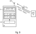
- Fig. 9 schematically illustrates a user device, UE, which, in accordance with embodiments of the second aspect of the present invention, maps a number of blind decodings to be performed by a UE and a minimum time between a control message and a corresponding data channel.
- the UE includes an antenna ANT to receive transmissions from a transmitter, like a gNB, for example, via the Uu interface, or from another UE over a sidelink, for example, using the PC5 interface.
- the UE comprises a processor P to process the transmissions received and to perform blind decoding in a certain search space, for example, indicated in a DCI or SCI, to find control data.
- the minimum time T stored in the memory indicates a time between a control message, like a DCI or a SCI, and a corresponding data channel, like the PDSCH or the PUSCH in case a transmission on the Uu interface, or the PSSCH in case a transmission on the sidelink.
- the UE sets the number of blind decodings (#BDs) to be performed dependent on the minimum time T, which may be signaled by the gNB. For example, in case the UE receives a first value T1 for the minimum time, like K2min, a first number v1 of BDs per slot may be performed, for example, a maximum number of BDs per slot. In case the UE receives a value T2 for the minimum time T that is lower than the initial value, the UE performs only a smaller number of BDs per slot which is less than the maximum number of BDs per slot. For example, for larger values the UE may be able to perform, dependent on the subcarrier spacing, 44 BDs per slot.
- #BDs number of blind decodings
- the UE performs only the first 44 BDs.
- the gNB indicates a smaller minimum time value, like a smaller K2min or K0min value, the UE, in view of its capabilities, determines that only a smaller number of BDs per slot may be performed, so that, for example, the number of BDs per slot may be reduced to 22.
- the minimum time value used at the UE may be signaled by the gNB to the UE or may be otherwise known by the gNB.
- the gNB does not schedule the corresponding UE outside the first 22 PDCCH candidates, when the UE uses a shorter minimum time T. Although this may reduce the scheduling flexibility within a CORESET, it has the advantage that it allows the gNB to schedule the UE faster.
- the gNB may select a minimum time value to be signaled to the UE from two or more available minimum time values so that the UE may set the number of blind decodings not only to a first value in accordance with the first minimum time, like 44 BDs and to a second value for the second minimum time value, like 22 BDs, but also to BDs between the two values or below the second value.
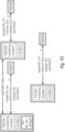
- Fig. 10 illustrates an embodiment of changing a number of blind decodings dependent on a minimum time between a control message and a corresponding data channel. It is assumed that a UE is initially operating with a relaxed K0min value, i.e., a minimum time allowing to perform, for example, 44 BDs. In the first PDCCH monitoring occasion PDCCH1, the UE receives from the gNB a more stringent, i.e., shorter K0min, for example, in a DCI. After a certain application delay, in a PDCCH monitoring occasion PDCCH3 a lower number of BDs, for example, 22 BDs are performed. Fig.
- the UE determines a maximum number of blind decodings the UE is capable to perform.
- the UE is preconfigured with a mapping between the minimum time and the number of blind decodings, or, responsive to signaling its capability to the wireless communication system, the UE is configured with the mapping, e.g., by receiving from the wireless communication system a configuration indicating the mapping between the minimum time and the number of blind decodings.
- one or more optional search spaces or CORESETs may be provided.
- An optional search space and/or CORESET may be activated/deactivated responsive to the indication of the parameter indicating the minimum time, like the K2min and/or the K0min parameter.
- the search space may be marked as optional or may be linked to a certain set of constraints including a certain value for the minimum time, so that the additional search space is only available if the constraints are met.
- the additional search space may be made available, for example, by setting a flag in the CORESET configuration that is transmitted to the UE.
- the UE in case the received value for the minimum time from the gNB is above the threshold performs the higher number of blind decodings not only in the search space so far defined but also in the additional search space indicated, for example, by the CORESET configuration.
- Fig. 11 schematically illustrates a user device, UE, which, in accordance with further embodiments of the second aspect of the present invention, maps a set of search spaces to be monitored by a UE and a minimum time between a control message and a corresponding data channel.
- the UE includes an antenna ANT to receive transmissions from a transmitter, like a gNB, for example, via the Uu interface, or from another UE over a sidelink, for example, using the PC5 interface.
- the UE comprises a processor P to process the transmissions received and to perform blind decodings to find control data.
- the UE further includes a storage M holding a minimum time T, for example, K0min or K2min, and the processor P receives from the memory M the minimum time stored.
- the UE monitors a first set (s1) of search spaces, and in case the minimum time T stored in a memory M is a second time T2 which is larger than T1, like K2min, the UE monitors a second set (s2) of search spaces, the first and second sets being different in the number of blind decodes.
- the first set having a smaller number of blind decodes.
- the UE is preconfigured with a mapping between the minimum time and the set of search spaces, or, responsive to signaling its capability to the wireless communication system, the UE is configured with the mapping, e.g., by receiving from the wireless communication system a configuration indicating the mapping between the minimum time and the set of search spaces.
- the UE receives, e.g., using an RRC signaling in response to signaling the UE capability to the wireless communication system, a plurality of search space configurations, the plurality of search space configurations indicating for different values for the minimum time the set of search spaces to be monitored by the UE.
- the parameter minimumK0min_K2_min indicates the minimum value for the time between control and data, i.e. K0min and/or K2min, for which this search space is applicable. All other parameters in the example below are existing parameters.
- the change of the minimum time value is effective only after a certain, well-defined application delay so that even if the gNB indicates a different minimum time value, like a different K0min and/or K2min value, the associated change may take a while to consider the changed operation mode.
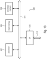
- Fig. 12 schematically illustrates a base station, like a gNB, in accordance with embodiments of the second aspect of the present invention.
- the gNB is to serve one or more UEs, of which one or more may be a UE operating in accordance with the second aspect of the present invention, for example, a UE as explained above with reference to Fig. 9 or Fig. 11 .
- the gNB is to select a minimum time and to send the minimum time to the UE so as to allow the UE to determine the number of blind decodings to be performed or the set of search space to be monitored.
- the wireless communication system may include a terrestrial network, or a non-terrestrial network, or networks or segments of networks using as a receiver an airborne vehicle or a spaceborne vehicle, or a combination thereof.
- the user device, UE may be one or more of a mobile terminal, or a stationary terminal, or a cellular IoT-UE, or a vehicular UE, or a vehicular group leader (GL) UE, or an loT, or a narrowband loT, NB-loT, device, or a WiFi non Access Point STAtion, non-AP STA, e.g., 802.11ax or 802.11be, or a ground based vehicle, or an aerial vehicle, or a drone, or a moving base station, or a road side unit, or a building, or any other item or device provided with network connectivity enabling the item/device to communicate using the wireless communication network, e.g., a sensor or actuator, or any other item or device provided with network connectivity enabling the item/device to communicate using a sidelink the wireless communication network, e.g., a sensor or actuator, or any sidelink capable network entity.
- a mobile terminal or a stationary terminal, or a cellular IoT
- the base station, BS may be implemented as mobile or immobile base station and may be one or more of a macro cell base station, or a small cell base station, or a central unit of a base station, or a distributed unit of a base station, or a road side unit, or a UE, or a group leader (GL), or a relay, or a remote radio head, or an AMF, or an SMF, or a core network entity, or mobile edge computing entity, or a network slice as in the NR or 5G core context, or a WiFi AP STA, e.g., 802.11ax or 802.11be, or any transmission/reception point, TRP, enabling an item or a device to communicate using the wireless communication network, the item or device being provided with network connectivity to communicate using the wireless communication network.
- a WiFi AP STA e.g., 802.11ax or 802.11be, or any transmission/reception point, TRP, enabling an item or a device to communicate using the wireless communication network
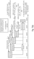
- the computer system 500 includes one or more processors 502, like a special purpose or a general-purpose digital signal processor.
- the processor 502 is connected to a communication infrastructure 504, like a bus or a network.
- the computer system 500 includes a main memory 506, e.g., a random-access memory (RAM), and a secondary memory 508, e.g., a hard disk drive and/or a removable storage drive.
- the secondary memory 508 may allow computer programs or other instructions to be loaded into the computer system 500.
- the computer system 500 may further include a communications interface 510 to allow software and data to be transferred between computer system 500 and external devices.
- the communication may be in the from electronic, electromagnetic, optical, or other signals capable of being handled by a communications interface.
- the communication may use a wire or a cable, fiber optics, a phone line, a cellular phone link, an RF link and other communications channels 512.
- a further embodiment of the inventive methods is, therefore, a data carrier (or a digital storage medium, or a computer-readable medium) comprising, recorded thereon, the computer program for performing one of the methods described herein.
- a further embodiment of the inventive method is, therefore, a data stream or a sequence of signals representing the computer program for performing one of the methods described herein. The data stream or the sequence of signals may for example be configured to be transferred via a data communication connection, for example via the Internet.
- a further embodiment comprises a processing means, for example a computer, or a programmable logic device, configured to or adapted to perform one of the methods described herein.
- a further embodiment comprises a computer having installed thereon the computer program for performing one of the methods described herein.
Landscapes
- Engineering & Computer Science (AREA)
- Signal Processing (AREA)
- Computer Networks & Wireless Communication (AREA)
- Databases & Information Systems (AREA)
- Quality & Reliability (AREA)
- Mobile Radio Communication Systems (AREA)
Applications Claiming Priority (3)
| Application Number | Priority Date | Filing Date | Title |
|---|---|---|---|
| EP20156219 | 2020-02-07 | ||
| EP21700610.5A EP4101249B1 (de) | 2020-02-07 | 2021-01-21 | Dynamische verarbeitungszeit und dynamische blinddecodierfähigkeit für nr-benutzergeräte |
| PCT/EP2021/051372 WO2021156071A1 (en) | 2020-02-07 | 2021-01-21 | Dynamic processing time and dynamic blind decoding capability for nr user devices |
Related Parent Applications (1)
| Application Number | Title | Priority Date | Filing Date |
|---|---|---|---|
| EP21700610.5A Division EP4101249B1 (de) | 2020-02-07 | 2021-01-21 | Dynamische verarbeitungszeit und dynamische blinddecodierfähigkeit für nr-benutzergeräte |
Publications (2)
| Publication Number | Publication Date |
|---|---|
| EP4535700A2 true EP4535700A2 (de) | 2025-04-09 |
| EP4535700A3 EP4535700A3 (de) | 2025-06-25 |
Family
ID=69645873
Family Applications (2)
| Application Number | Title | Priority Date | Filing Date |
|---|---|---|---|
| EP24219456.1A Pending EP4535700A3 (de) | 2020-02-07 | 2021-01-21 | Dynamische verarbeitungszeit und dynamische blinddecodierungsfähigkeit für nr-benutzervorrichtungen |
| EP21700610.5A Active EP4101249B1 (de) | 2020-02-07 | 2021-01-21 | Dynamische verarbeitungszeit und dynamische blinddecodierfähigkeit für nr-benutzergeräte |
Family Applications After (1)
| Application Number | Title | Priority Date | Filing Date |
|---|---|---|---|
| EP21700610.5A Active EP4101249B1 (de) | 2020-02-07 | 2021-01-21 | Dynamische verarbeitungszeit und dynamische blinddecodierfähigkeit für nr-benutzergeräte |
Country Status (5)
| Country | Link |
|---|---|
| US (1) | US12549963B2 (de) |
| EP (2) | EP4535700A3 (de) |
| KR (1) | KR102734980B1 (de) |
| CN (1) | CN115349243B (de) |
| WO (1) | WO2021156071A1 (de) |
Families Citing this family (6)
| Publication number | Priority date | Publication date | Assignee | Title |
|---|---|---|---|---|
| US11943730B2 (en) * | 2020-07-13 | 2024-03-26 | Qualcomm Incorporated | Search space specific delay between a downlink control channel and corresponding downlink/uplink data |
| CN114362895B (zh) * | 2020-10-12 | 2024-06-25 | 维沃移动通信有限公司 | 反馈信息传输方法、终端及网络设备 |
| US12342352B2 (en) * | 2021-09-30 | 2025-06-24 | Qualcomm Incorporated | Flexible slot group for multiple slot control channel monitoring |
| CN116418462B (zh) * | 2021-12-29 | 2025-12-02 | 维沃移动通信有限公司 | 处理时间确定方法、装置、终端和存储介质 |
| WO2024159405A1 (en) * | 2023-01-31 | 2024-08-08 | Nokia Shanghai Bell Co., Ltd. | Processing time relaxation |
| CN117956588A (zh) * | 2023-05-12 | 2024-04-30 | 中兴通讯股份有限公司 | 一种物理信道的接收、发送方法、通信装置及存储介质 |
Family Cites Families (12)
| Publication number | Priority date | Publication date | Assignee | Title |
|---|---|---|---|---|
| KR100968020B1 (ko) * | 2008-06-18 | 2010-07-08 | 엘지전자 주식회사 | 랜덤 액세스 절차를 수행하는 방법 및 그 단말 |
| CN102215577B (zh) * | 2010-04-02 | 2015-09-16 | 中兴通讯股份有限公司 | 回程链路上行控制信道的资源分配方法和系统 |
| EP2782409A1 (de) * | 2013-03-20 | 2014-09-24 | Panasonic Intellectual Property Corporation of America | Deterministisches UE-Verhalten für die CSI/SRS-Berichterstattung während DRX |
| US10129858B2 (en) * | 2014-11-25 | 2018-11-13 | Qualcomm Incorporated | Low latency physical layer design for contention-based uplink channels |
| US10595166B2 (en) * | 2016-07-18 | 2020-03-17 | Sharp Kabushiki Kaisha | Systems and methods for processing time reduction signaling |
| US20190215906A1 (en) * | 2016-11-04 | 2019-07-11 | Intel IP Corporation | Signaling to support reduced processing time |
| JP7426171B2 (ja) * | 2018-07-06 | 2024-02-01 | 株式会社Nttドコモ | 端末、無線通信方法、基地局及びシステム |
| JP7447782B2 (ja) * | 2020-12-23 | 2024-03-12 | 株式会社オートネットワーク技術研究所 | 車載コンピュータ、コンピュータ実行方法及びコンピュータプログラム |
| US20230126370A1 (en) * | 2021-10-21 | 2023-04-27 | Qualcomm Incorporated | Techniques for bandwidth part switching |
| EP4497261A4 (de) * | 2022-04-27 | 2025-07-23 | Samsung Electronics Co Ltd | Benutzergerät, basisstation und davon durchgeführtes verfahren |
| US20230403110A1 (en) * | 2022-06-14 | 2023-12-14 | Qualcomm Incorporated | Waveform switching for downlink transmissions |
| JP2024115220A (ja) * | 2023-02-14 | 2024-08-26 | 株式会社東芝 | 制御システム、制御装置及び方法 |
-
2021
- 2021-01-21 EP EP24219456.1A patent/EP4535700A3/de active Pending
- 2021-01-21 EP EP21700610.5A patent/EP4101249B1/de active Active
- 2021-01-21 CN CN202180026024.2A patent/CN115349243B/zh active Active
- 2021-01-21 WO PCT/EP2021/051372 patent/WO2021156071A1/en not_active Ceased
- 2021-01-21 KR KR1020227031269A patent/KR102734980B1/ko active Active
-
2022
- 2022-08-04 US US17/881,424 patent/US12549963B2/en active Active
Also Published As
| Publication number | Publication date |
|---|---|
| EP4535700A3 (de) | 2025-06-25 |
| US20230079377A1 (en) | 2023-03-16 |
| EP4101249B1 (de) | 2024-12-18 |
| CN115349243B (zh) | 2024-07-16 |
| US12549963B2 (en) | 2026-02-10 |
| WO2021156071A1 (en) | 2021-08-12 |
| KR20220148199A (ko) | 2022-11-04 |
| CN115349243A (zh) | 2022-11-15 |
| KR102734980B1 (ko) | 2024-11-28 |
| EP4101249A1 (de) | 2022-12-14 |
Similar Documents
| Publication | Publication Date | Title |
|---|---|---|
| US12155472B2 (en) | Sidelink feedback | |
| CN113303020B (zh) | 无线通信系统中的处理两步随机接入过程中的msg a重传的方法和设备 | |
| JP7453985B2 (ja) | 新無線設定されたアップリンク(ul)のための時間リソース | |
| US12549963B2 (en) | Dynamic processing time and dynamic blind decoding capability for NR user devices | |
| US20240348374A1 (en) | Low latency harq protocol for urllc services | |
| RU2577481C2 (ru) | Перекрестное планирование для ответа о произвольном доступе | |
| US11876624B2 (en) | Method for transmitting data by means of terminal in wireless communication system supporting sidelink, and device therefor | |
| US11917611B2 (en) | Method and apparatus for receiving UE to perform power saving operation based on PSFCH in NR V2X | |
| US20230180266A1 (en) | Method and apparatus for determining non-preferred resource in wireless communication system | |
| EP3876464A1 (de) | Internet-of-vehicles-datenübertragungsverfahren, übertragungsendgerät und netzseitige vorrichtung | |
| EP3729710B1 (de) | Durch benutzervorrichtung initiierte datenübertragungen mit geringer latenz | |
| US12207293B2 (en) | Random access channel procedures | |
| WO2022207844A1 (en) | Control channel monitoring enhancements | |
| JP2023529731A (ja) | Nr v2xにおける資源割当モード2動作ベースのsl drxタイマー動作方法及び装置 | |
| US20240275528A1 (en) | Method and apparatus for performing sl drx operation in nr v2x | |
| US20240073929A1 (en) | Method and device for prioritizing harq feedback in nr v2x | |
| US12501348B2 (en) | Method and apparatus for transmitting signal in wireless communication system | |
| US20240032140A1 (en) | Method and apparatus for performing sl communication on basis of sl drx configurations in nr v2x | |
| CN111147193B (zh) | 一种车联网的重传请求方法、终端和网络侧设备 | |
| US20230164770A1 (en) | Method and apparatus for performing sl drx operation in nr v2x | |
| US20240260055A1 (en) | Method and apparatus for performing sl drx operation in nr v2x | |
| US20240284492A1 (en) | Method and device for performing sl drx operation in nr v2x | |
| US20230276487A1 (en) | Method and apparatus for transmitting signal in wireless communication system | |
| WO2024095679A1 (ja) | 端末、基地局、及び通信方法 | |
| KR20250078524A (ko) | 사이드링크 통신용 lbt를 처리하기 위한 방법 및 장치 |
Legal Events
| Date | Code | Title | Description |
|---|---|---|---|
| PUAI | Public reference made under article 153(3) epc to a published international application that has entered the european phase |
Free format text: ORIGINAL CODE: 0009012 |
|
| STAA | Information on the status of an ep patent application or granted ep patent |
Free format text: STATUS: THE APPLICATION HAS BEEN PUBLISHED |
|
| AC | Divisional application: reference to earlier application |
Ref document number: 4101249 Country of ref document: EP Kind code of ref document: P |
|
| AK | Designated contracting states |
Kind code of ref document: A2 Designated state(s): AL AT BE BG CH CY CZ DE DK EE ES FI FR GB GR HR HU IE IS IT LI LT LU LV MC MK MT NL NO PL PT RO RS SE SI SK SM TR |
|
| PUAL | Search report despatched |
Free format text: ORIGINAL CODE: 0009013 |
|
| AK | Designated contracting states |
Kind code of ref document: A3 Designated state(s): AL AT BE BG CH CY CZ DE DK EE ES FI FR GB GR HR HU IE IS IT LI LT LU LV MC MK MT NL NO PL PT RO RS SE SI SK SM TR |
|
| RIC1 | Information provided on ipc code assigned before grant |
Ipc: H04W 88/02 20090101ALI20250521BHEP Ipc: H04W 88/08 20090101ALI20250521BHEP Ipc: H04W 76/00 20180101ALI20250521BHEP Ipc: H04W 8/24 20090101ALI20250521BHEP Ipc: H04L 5/00 20060101ALI20250521BHEP Ipc: H04L 1/1829 20230101AFI20250521BHEP |
|
| STAA | Information on the status of an ep patent application or granted ep patent |
Free format text: STATUS: REQUEST FOR EXAMINATION WAS MADE |
|
| 17P | Request for examination filed |
Effective date: 20251223 |