EP4535632A1 - Resonant hybrid flyback converter for a light source, and luminaire - Google Patents
Resonant hybrid flyback converter for a light source, and luminaire Download PDFInfo
- Publication number
- EP4535632A1 EP4535632A1 EP23201763.2A EP23201763A EP4535632A1 EP 4535632 A1 EP4535632 A1 EP 4535632A1 EP 23201763 A EP23201763 A EP 23201763A EP 4535632 A1 EP4535632 A1 EP 4535632A1
- Authority
- EP
- European Patent Office
- Prior art keywords
- inductance
- sub
- light source
- primary
- current
- Prior art date
- Legal status (The legal status is an assumption and is not a legal conclusion. Google has not performed a legal analysis and makes no representation as to the accuracy of the status listed.)
- Withdrawn
Links
Images


Classifications
-
- H—ELECTRICITY
- H02—GENERATION; CONVERSION OR DISTRIBUTION OF ELECTRIC POWER
- H02M—APPARATUS FOR CONVERSION BETWEEN AC AND AC, BETWEEN AC AND DC, OR BETWEEN DC AND DC, AND FOR USE WITH MAINS OR SIMILAR POWER SUPPLY SYSTEMS; CONVERSION OF DC OR AC INPUT POWER INTO SURGE OUTPUT POWER; CONTROL OR REGULATION THEREOF
- H02M3/00—Conversion of DC power input into DC power output
- H02M3/22—Conversion of DC power input into DC power output with intermediate conversion into AC
- H02M3/24—Conversion of DC power input into DC power output with intermediate conversion into AC by static converters
- H02M3/28—Conversion of DC power input into DC power output with intermediate conversion into AC by static converters using discharge tubes with control electrode or semiconductor devices with control electrode to produce the intermediate AC
- H02M3/325—Conversion of DC power input into DC power output with intermediate conversion into AC by static converters using discharge tubes with control electrode or semiconductor devices with control electrode to produce the intermediate AC using devices of a triode or a transistor type requiring continuous application of a control signal
- H02M3/335—Conversion of DC power input into DC power output with intermediate conversion into AC by static converters using discharge tubes with control electrode or semiconductor devices with control electrode to produce the intermediate AC using devices of a triode or a transistor type requiring continuous application of a control signal using semiconductor devices only
- H02M3/33507—Conversion of DC power input into DC power output with intermediate conversion into AC by static converters using discharge tubes with control electrode or semiconductor devices with control electrode to produce the intermediate AC using devices of a triode or a transistor type requiring continuous application of a control signal using semiconductor devices only with automatic control of the output voltage or current, e.g. flyback converters
- H02M3/33523—Conversion of DC power input into DC power output with intermediate conversion into AC by static converters using discharge tubes with control electrode or semiconductor devices with control electrode to produce the intermediate AC using devices of a triode or a transistor type requiring continuous application of a control signal using semiconductor devices only with automatic control of the output voltage or current, e.g. flyback converters with galvanic isolation between input and output of both the power stage and the feedback loop
-
- H—ELECTRICITY
- H02—GENERATION; CONVERSION OR DISTRIBUTION OF ELECTRIC POWER
- H02M—APPARATUS FOR CONVERSION BETWEEN AC AND AC, BETWEEN AC AND DC, OR BETWEEN DC AND DC, AND FOR USE WITH MAINS OR SIMILAR POWER SUPPLY SYSTEMS; CONVERSION OF DC OR AC INPUT POWER INTO SURGE OUTPUT POWER; CONTROL OR REGULATION THEREOF
- H02M1/00—Details of apparatus for conversion
- H02M1/0003—Details of control, feedback or regulation circuits
- H02M1/0009—Devices or circuits for detecting current in a converter
-
- H—ELECTRICITY
- H02—GENERATION; CONVERSION OR DISTRIBUTION OF ELECTRIC POWER
- H02M—APPARATUS FOR CONVERSION BETWEEN AC AND AC, BETWEEN AC AND DC, OR BETWEEN DC AND DC, AND FOR USE WITH MAINS OR SIMILAR POWER SUPPLY SYSTEMS; CONVERSION OF DC OR AC INPUT POWER INTO SURGE OUTPUT POWER; CONTROL OR REGULATION THEREOF
- H02M1/00—Details of apparatus for conversion
- H02M1/0095—Hybrid converter topologies, e.g. NPC mixed with flying capacitor, thyristor converter mixed with MMC or charge pump mixed with buck
-
- H—ELECTRICITY
- H02—GENERATION; CONVERSION OR DISTRIBUTION OF ELECTRIC POWER
- H02M—APPARATUS FOR CONVERSION BETWEEN AC AND AC, BETWEEN AC AND DC, OR BETWEEN DC AND DC, AND FOR USE WITH MAINS OR SIMILAR POWER SUPPLY SYSTEMS; CONVERSION OF DC OR AC INPUT POWER INTO SURGE OUTPUT POWER; CONTROL OR REGULATION THEREOF
- H02M3/00—Conversion of DC power input into DC power output
- H02M3/01—Resonant DC/DC converters
Definitions
- the present disclosure relates generally to the field of lighting technology, and in particular to a resonant hybrid flyback converter implementing a primary-side current sensing, and to a luminaire comprising the converter.
- a direct current (DC) input voltage is intermittently applied across a resonant tank circuit.
- the resonant tank circuit may, for example, comprise a transformer's main inductance and leakage inductance (or a separate resonance choke) and a resonance capacitance in series.
- An on-time control of a high-side switch of the switching bridge may be deployed for regulation (i.e., closed-loop control) of a load current of the converter in accordance with corresponding setpoint and measurement values.
- a sensing of the latter typically involves a relatively expensive signal transfer across a safety extra low voltage (SELV) barrier of the converter.
- SELV safety extra low voltage
- a resonant hybrid flyback converter for a light source.
- the converter comprises a transformer, comprising a primary-side inductance and a secondary-side inductance; a high-side switch and a low-side switch, connected in series between an input electric potential and a primary-side ground electric potential of the converter; a resonant tank circuit, connected in series between a common electric potential of the switches and the primary-side ground electric potential, wherein the resonant tank circuit comprises the primary-side inductance.
- the converter further comprises a current sensing circuit, configured to sense a positive peak current through the primary-side inductance; a voltage sensing circuit, configured to sense a voltage across an inductance of the transformer; and a control circuit, configured to estimate a current through the light source in accordance with the positive peak current through the primary-side inductance and the voltage across the inductance of the transformer; and regulate the current through the light source in accordance with a setpoint value and the estimated current through the light source.
- a current sensing circuit configured to sense a positive peak current through the primary-side inductance
- a voltage sensing circuit configured to sense a voltage across an inductance of the transformer
- a control circuit configured to estimate a current through the light source in accordance with the positive peak current through the primary-side inductance and the voltage across the inductance of the transformer; and regulate the current through the light source in accordance with a setpoint value and the estimated current through the light source.
- the transformer may further comprise an auxiliary inductance in inductive communication with the primary-side inductance; wherein the voltage sensing circuit may comprise the auxiliary inductance, referenced to the primary-side ground electric potential; a peak current detection circuit, connected in parallel to the auxiliary inductance and comprising a diode and a capacitance; and a resistive voltage divider, connected in parallel to the capacitance.
- the voltage across the inductance of the transformer may comprise a voltage across the secondary-side inductance, in turn comprising a divided voltage of the resistive voltage divider, further divided by a turns ratio of the transformer.
- the control circuit may further configured to estimate the current through the light source in accordance with the positive peak current through the primary-side inductance, the voltage across the secondary-side inductance, the turns ratio of the transformer, a main inductance of the primary-side inductance, and a constant on-time duration of the low-side switch.
- the voltage across the inductance of the transformer may comprise a voltage across the primary-side inductance, in turn comprising a divided voltage of the resistive voltage divider.
- the control circuit may further be configured to estimate the current through the light source in accordance with the positive peak current through the primary-side inductance, the voltage across the primary-side inductance, the turns ratio of the transformer, the main inductance of the primary-side inductance, and an on-time duration of the high-side switch.
- the control circuit may further be configured to sample the divided voltage of the resistive voltage divider once, more than once, or continuously during the respective on-time duration of the high-side switch; or sample the divided voltage of the resistive voltage divider once, more than once, or continuously during the respective on-time duration of the low-side switch.
- control circuit may further be configured to regulate the current through the light source in accordance with a setpoint value, the estimated current through the light source, and an on-time control of the high-side switch.
- control circuit may further be configured to regulate the current through the light source in accordance with a setpoint value, the estimated current through the light source, and a peak current control of the high-side switch in accordance with the positive peak current through the primary-side inductance.
- a luminaire comprising a light source; and a resonant hybrid flyback converter of the first aspect for the light source.
- the light source may comprise at least one light-emitting diode, LED.
- a disclosure in connection with a described method may also hold true for a corresponding apparatus or system configured to perform the method and vice versa.
- a corresponding device may include one or a plurality of units, e.g. functional units, to perform the described one or plurality of method steps (e.g. one unit performing the one or plurality of steps, or a plurality of units each performing one or more of the plurality of steps), even if such one or more units are not explicitly described or illustrated in the figures.
- a specific apparatus is described based on one or a plurality of units, e.g.
- a corresponding method may include one step to perform the functionality of the one or plurality of units (e.g. one step performing the functionality of the one or plurality of units, or a plurality of steps each performing the functionality of one or more of the plurality of units), even if such one or plurality of steps are not explicitly described or illustrated in the figures. Further, it is understood that the features of the various exemplary implementations and/or aspects described herein may be combined with each other, unless specifically noted otherwise.
- FIG. 1 illustrates a converter 1 in accordance with the present disclosure.
- the converter 1 comprises a resonant hybrid flyback converter 1 for a light source 4, which may comprise at least one light-emitting diode (LED).
- a light source 4 which may comprise at least one light-emitting diode (LED).
- the converter 1 and the light source 4 form part of a luminaire 1,4.
- the converter 1 comprises a transformer 101, 102, including a primary-side inductance 101, L p and a secondary-side inductance 102, L s .
- the primary-side inductance 101, L p may in turn comprise a main inductance 101', L m and a leakage inductance 101", L lk .
- the transformer 101, 102 may further comprise an auxiliary inductance 103, L aux in inductive communication with the primary-side inductance 101, L p
- the converter 1 further comprises a high-side (HS) switch 104 and a low-side (LS) switch 105, connected in series between an input electric potential and a primary-side ground electric potential of the converter 1 .
- the switches 104, 105 may form part of a switching half-bridge (HB) or full bridge (FB), for example.
- the converter 1 further comprises a resonant tank circuit 101, 106, connected in series between a common electric potential of the switches 104, 105 and the primary-side ground electric potential.
- the resonant tank circuit 101, 106 comprises the primary-side inductance 101, L p or more precisely, its main inductance 101 ', L m , its leakage/resonance inductance 101 ", L lk , and a resonance capacitance 106, C res . (i.e., an LLC resonant tank).
- the converter 1 further comprises a half-wave rectifying and smoothing circuit including a diode D out and a capacitance C out .
- the converter 1 further comprises a current sensing circuit (not shown), configured to sense a positive peak current 301, I magpos through the primary-side inductance 101, L p .
- the current sensing circuit may comprise a shunt resistor arranged in series with the primary-side inductance 101, L p . such that a voltage emerging across the shunt resistor is indicative of the current 301 through the primary-side inductance 101, L p .
- the converter 1 further comprises a voltage sensing circuit 103, 107-110, configured to sense a voltage 302, V Lmsec ; 302', V Lmprim across an inductance 101, 102 of the transformer 101, 102.
- the voltage sensing circuit 103, 107-110 may comprise the auxiliary inductance 103, L aux , referenced to the primary-side ground electric potential; a peak current detection circuit 107, D; 108, C, connected in parallel to the auxiliary inductance 103, L aux and comprising a diode 107, D and a capacitance 108, C ; and a resistive voltage divider 109, R; 110, R, connected in parallel to the capacitance 108, C . Note that resistance values of the elements of the resistive voltage divider 109, R; 110, R do not necessarily coincide.
- the converter 1 further comprises a control circuit (not shown) such as an application-specific integrated circuit (ASIC) or the like.
- a control circuit such as an application-specific integrated circuit (ASIC) or the like.
- the control circuit is configured to estimate a current 303, I LEDest through the light source 4 in accordance with the positive peak current 301, I magpos through the primary-side inductance 101, L p and the voltage 302, V Lmsec ; 302', V Lmprim across the inductance 101, 102 of the transformer 101, 102.
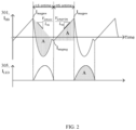
- FIG. 2 illustrates electrical quantities of the converter 1 of FIG. 1 over the course of time, namely the (half-bridge) current 301, I HB through the primary-side inductance 101, L p in an upper section and a current 305, I LED through the light source 4 (i.e., load / LED current) in a lower section.
- I magneg I magpos ⁇ t LSon V Lmsec L m
- I LED N 2 2 I magpos ⁇ t LSon V Lmsec L m
- the voltage across the inductance 101, 102 of the transformer 101, 102 may comprise a voltage 302', V Lmsec across the secondary-side inductance 102, L s , in turn comprising the divided voltage V sns of the resistive voltage divider 109, R; 110; R , further divided by a turns ratio N of the transformer 101, 102.
- the control circuit may be configured to sample the divided voltage V sns of the resistive voltage divider 109, R; 110, R once, more than once, or continuously during a respective on-time duration t HSon of the high-side switch 104, and may further be configured to average the sampled values of the divided voltage V sns .
- the control circuit may further be configured to estimate the current 303, I LEDest through the light source 4 in accordance with the positive peak current 301, I magpos through the primary-side inductance 101, L p , the voltage 302', V Lmsec across the secondary-side inductance 102, L s , the turns ratio N of the transformer 101, 102, the main inductance 101', L m of the primary-side inductance 101, L p , and a constant on-time duration t LSon of the low-side switch 105.
- I magneg I magpos ⁇ t HSon V Lmprim L m
- I LED N 2 I magpos ⁇ t HSon V Lmprim L m
- the voltage across the inductance of the transformer 101, 102 may comprise a voltage 302, V Lmprim across the primary-side inductance 101, L p , in turn comprising a divided voltage V sns of the resistive voltage divider 109, R; 110, R.
- the control circuit may be configured to sample the divided voltage V sns of the resistive voltage divider 109, R; 110, R once, more than once, or continuously during the respective on-time duration t LSon of the low-side switch 105. Again, the control circuit may be configured to average the sampled values of the divided voltage V sns .
- the control circuit may further be configured to estimate the current 303, I LEDest through the light source 4 in accordance with the positive peak current 301, I magpos through the primary-side inductance 101, L p , the voltage 302, V Lmprim across the primary-side inductance 101, L p , the turns ratio N of the transformer 101, 102, the main inductance 101', L m of the primary-side inductance 101, L p , and an on-time duration t HSon of the high-side switch 104.
- the control circuit is further configured to regulate the current 305, I LED through the light source 4 in accordance with a setpoint value 304, I LEDref and the estimated current 303, I LEDest through the light source 4 .
- FIG. 3 illustrates a closed-loop control of the converter 1 of FIG. 1 adapted for on-time control.
- the control circuit may be configured to regulate the current 305, I LED through the light source 4 in accordance with the setpoint value 304, I LEDref , the estimated current 303, I LEDest through the light source 4 , and an on-time control of the high-side switch 104.
- the on-time control of the high-side switch 104 may be based on the estimated current 303, I LEDest through the light source 4 rather than on the actual current 305, I LED through the light source 4 .
- FIG. 4 illustrates a closed-loop control of the converter 1 of FIG. 1 adapted for peak control.
- the control circuit may further be configured to regulate the current 305, I LED through the light source 4 in accordance with a setpoint value 304, I LEDref , the estimated current 303, I LEDest through the light source 4 , and a peak current control of the high-side switch 104 in accordance with the positive peak current 301, I magpos through the primary-side inductance 101, L p .
- the peak current control of the high-side switch 104 may be based on a comparison of an instantaneous current 301 through the primary-side inductance 101, L p and the positive peak current 301, I magpos through the primary-side inductance 101, L p , wherein the latter serves as a reference. Once the former exceeds the latter, the high-side switch 104 may be switched off.
- a computer program may be stored/distributed on a suitable medium, such as an optical storage medium or a solid-state medium supplied together with or as part of other hardware, but may also be distributed in other forms, such as via the Internet or other wired or wireless telecommunication systems.
- a suitable medium such as an optical storage medium or a solid-state medium supplied together with or as part of other hardware, but may also be distributed in other forms, such as via the Internet or other wired or wireless telecommunication systems.
Landscapes
- Engineering & Computer Science (AREA)
- Power Engineering (AREA)
- Circuit Arrangement For Electric Light Sources In General (AREA)
- Dc-Dc Converters (AREA)
Abstract
Disclosed is a resonant hybrid flyback converter (1) for a light source (4). The converter (1) comprises a transformer (101, 102), comprising a primary-side inductance (101, L<sub>p</sub>) and a secondary-side inductance (102, L<sub>s</sub>); a high-side switch (104) and a low-side switch (105), connected in series between an input electric potential and a primary-side ground electric potential of the converter (1); a resonant tank circuit (101, 101", 106), connected in series between a common electric potential of the switches (104, 105) and the primary-side ground electric potential, wherein the resonant tank circuit (101, 101", 106) comprises the primary-side inductance (101, L<sub>p</sub>). The converter (1) further comprises a current sensing circuit, configured to sense a positive peak current (301, I<sub>magpos</sub>) through the primary-side inductance (101, L<sub>p</sub>); a voltage sensing circuit (103, 107-110), configured to sense a voltage (302, V<sub>Lmsec</sub>; 302', V<sub>Lmpri</sub>) across an inductance (101, 102) of the transformer (101, 102); and a control circuit, configured to estimate a current (303, I<sub>LEDest</sub>) through the light source (4) in accordance with the positive peak current (301, I<sub>magpos</sub>) through the primary-side inductance (101, L<sub>p</sub>) and the voltage (302, V<sub>Lmsec</sub>; 302', V<sub>Lmpri</sub>) across the inductance (101, 102) of the transformer (101, 102); and regulate the current (305, I<sub>LED</sub>) through the light source (4) in accordance with a setpoint value (304, I<sub>LEDref</sub>) and the estimated current (303, I<sub>LEDest</sub>) through the light source (4). This avoids a sensing of the current (305, I<sub>LED</sub>) through the light source (4) and an associated signal transfer across a SELV barrier of the converter (1).
Description
- The present disclosure relates generally to the field of lighting technology, and in particular to a resonant hybrid flyback converter implementing a primary-side current sensing, and to a luminaire comprising the converter.
- In resonant hybrid flyback converters, a direct current (DC) input voltage is intermittently applied across a resonant tank circuit. The resonant tank circuit may, for example, comprise a transformer's main inductance and leakage inductance (or a separate resonance choke) and a resonance capacitance in series.
- An on-time control of a high-side switch of the switching bridge may be deployed for regulation (i.e., closed-loop control) of a load current of the converter in accordance with corresponding setpoint and measurement values. A sensing of the latter typically involves a relatively expensive signal transfer across a safety extra low voltage (SELV) barrier of the converter.
- It is an object to overcome the above-mentioned and other drawbacks.
- The foregoing and other objects are achieved by the features of the independent claims. Further implementation forms are apparent from the dependent claims, the description and the figures.
- According to a first aspect, a resonant hybrid flyback converter is provided for a light source. The converter comprises a transformer, comprising a primary-side inductance and a secondary-side inductance; a high-side switch and a low-side switch, connected in series between an input electric potential and a primary-side ground electric potential of the converter; a resonant tank circuit, connected in series between a common electric potential of the switches and the primary-side ground electric potential, wherein the resonant tank circuit comprises the primary-side inductance. The converter further comprises a current sensing circuit, configured to sense a positive peak current through the primary-side inductance; a voltage sensing circuit, configured to sense a voltage across an inductance of the transformer; and a control circuit, configured to estimate a current through the light source in accordance with the positive peak current through the primary-side inductance and the voltage across the inductance of the transformer; and regulate the current through the light source in accordance with a setpoint value and the estimated current through the light source.
- The transformer may further comprise an auxiliary inductance in inductive communication with the primary-side inductance; wherein the voltage sensing circuit may comprise the auxiliary inductance, referenced to the primary-side ground electric potential; a peak current detection circuit, connected in parallel to the auxiliary inductance and comprising a diode and a capacitance; and a resistive voltage divider, connected in parallel to the capacitance.
- The voltage across the inductance of the transformer may comprise a voltage across the secondary-side inductance, in turn comprising a divided voltage of the resistive voltage divider, further divided by a turns ratio of the transformer.
- The control circuit may further configured to estimate the current through the light source in accordance with the positive peak current through the primary-side inductance, the voltage across the secondary-side inductance, the turns ratio of the transformer, a main inductance of the primary-side inductance, and a constant on-time duration of the low-side switch.
- The voltage across the inductance of the transformer may comprise a voltage across the primary-side inductance, in turn comprising a divided voltage of the resistive voltage divider.
- The control circuit may further be configured to estimate the current through the light source in accordance with the positive peak current through the primary-side inductance, the voltage across the primary-side inductance, the turns ratio of the transformer, the main inductance of the primary-side inductance, and an on-time duration of the high-side switch.
- The control circuit may further be configured to sample the divided voltage of the resistive voltage divider once, more than once, or continuously during the respective on-time duration of the high-side switch; or sample the divided voltage of the resistive voltage divider once, more than once, or continuously during the respective on-time duration of the low-side switch.
- For regulating the current through the light source in accordance with a setpoint value and the estimated current through the light source, the control circuit may further be configured to regulate the current through the light source in accordance with a setpoint value, the estimated current through the light source, and an on-time control of the high-side switch.
- For regulating the current through the light source in accordance with a setpoint value and the estimated current through the light source, the control circuit may further be configured to regulate the current through the light source in accordance with a setpoint value, the estimated current through the light source, and a peak current control of the high-side switch in accordance with the positive peak current through the primary-side inductance.
- According to a second aspect, a luminaire is provided, comprising a light source; and a resonant hybrid flyback converter of the first aspect for the light source.
- The light source may comprise at least one light-emitting diode, LED.
- The above-described aspects and implementations will now be explained with reference to the accompanying drawings, in which the same or similar reference numerals designate the same or similar elements.
- The drawings are to be regarded as being schematic representations, and elements illustrated in the drawings are not necessarily shown to scale. Rather, the various elements are represented such that their function and general purpose become apparent to those skilled in the art.
- FIG. 1
- illustrates a converter in accordance with the present disclosure;
- FIG. 2
- illustrates electrical quantities of the converter of
FIG. 1 ; - FIG. 3
- illustrates a closed-loop control of the converter of
FIG. 1 adapted for on-time control; and - FIG. 4
- illustrates a closed-loop control of the converter of
FIG. 1 adapted for peak control. - In the following description, reference is made to the accompanying drawings, which form part of the disclosure, and which show, by way of illustration, specific aspects of implementations of the present disclosure or specific aspects in which implementations of the present disclosure may be used. It is understood that implementations of the present disclosure may be used in other aspects and comprise structural or logical changes not depicted in the figures. The following detailed description, therefore, is not to be taken in a limiting sense, and the scope of the present disclosure is defined by the appended claims.
- For instance, it is understood that a disclosure in connection with a described method may also hold true for a corresponding apparatus or system configured to perform the method and vice versa. For example, if one or a plurality of specific method steps are described, a corresponding device may include one or a plurality of units, e.g. functional units, to perform the described one or plurality of method steps (e.g. one unit performing the one or plurality of steps, or a plurality of units each performing one or more of the plurality of steps), even if such one or more units are not explicitly described or illustrated in the figures. On the other hand, for example, if a specific apparatus is described based on one or a plurality of units, e.g. functional units, a corresponding method may include one step to perform the functionality of the one or plurality of units (e.g. one step performing the functionality of the one or plurality of units, or a plurality of steps each performing the functionality of one or more of the plurality of units), even if such one or plurality of steps are not explicitly described or illustrated in the figures. Further, it is understood that the features of the various exemplary implementations and/or aspects described herein may be combined with each other, unless specifically noted otherwise.
-
FIG. 1 illustrates a converter 1 in accordance with the present disclosure. - Technically, the converter 1 comprises a resonant hybrid flyback converter 1 for a
light source 4, which may comprise at least one light-emitting diode (LED). - A resonant hybrid flyback converter as used herein may refer to a combination of a flyback converter (wherein a square-wave voltage is applied to a primary-side inductance of a transformer) and a resonant converter (wherein the square-wave voltage is applied to a resonant tank circuit), wherein the resonant tank circuit includes the primary-side inductance.
- In the non-limiting example of
FIG. 1 , the converter 1 and thelight source 4 form part of aluminaire 1,4. - The converter 1 comprises a
transformer side inductance 101, Lp and a secondary-side inductance 102, Ls. The primary-side inductance 101, Lp may in turn comprise a main inductance 101', Lm and aleakage inductance 101", Llk. - The
transformer auxiliary inductance 103, Laux in inductive communication with the primary-side inductance 101, Lp - The converter 1 further comprises a high-side (HS)
switch 104 and a low-side (LS)switch 105, connected in series between an input electric potential and a primary-side ground electric potential of the converter 1. Theswitches - The converter 1 further comprises a
resonant tank circuit switches - The
resonant tank circuit side inductance 101, Lp or more precisely, its main inductance 101 ', Lm, its leakage/resonance inductance 101 ", Llk, and aresonance capacitance 106, Cres. (i.e., an LLC resonant tank). - In the non-binding example, of
FIG. 1 , the converter 1 further comprises a half-wave rectifying and smoothing circuit including a diode Dout and a capacitance Cout . - The converter 1 further comprises a current sensing circuit (not shown), configured to sense a
positive peak current 301, Imagpos through the primary-side inductance 101, Lp. For example, the current sensing circuit may comprise a shunt resistor arranged in series with the primary-side inductance 101, Lp. such that a voltage emerging across the shunt resistor is indicative of the current 301 through the primary-side inductance 101, Lp. - The converter 1 further comprises a
voltage sensing circuit 103, 107-110, configured to sense avoltage 302, VLmsec; 302', VLmprim across aninductance transformer - The
voltage sensing circuit 103, 107-110 may comprise theauxiliary inductance 103, Laux, referenced to the primary-side ground electric potential; a peakcurrent detection circuit 107, D; 108, C, connected in parallel to theauxiliary inductance 103, Laux and comprising adiode 107, D and acapacitance 108, C; and aresistive voltage divider 109, R; 110, R, connected in parallel to thecapacitance 108, C. Note that resistance values of the elements of theresistive voltage divider 109, R; 110, R do not necessarily coincide. - The converter 1 further comprises a control circuit (not shown) such as an application-specific integrated circuit (ASIC) or the like.
- The control circuit is configured to estimate a current 303, ILEDest through the
light source 4 in accordance with thepositive peak current 301, Imagpos through the primary-side inductance 101, Lp and thevoltage 302, VLmsec; 302', VLmprim across theinductance transformer -
FIG. 2 illustrates electrical quantities of the converter 1 ofFIG. 1 over the course of time, namely the (half-bridge) current 301, IHB through the primary-side inductance 101, Lp in an upper section and a current 305, ILED through the light source 4 (i.e., load / LED current) in a lower section. - Note that the hatched areas respectively designated as 'A' correspond to one another in terms of size/area.
- Based on the hatched triangular area bounded by the upper curve, it may be derived that:

- From the hatched rounded area bounded by the upper curve, it may further be concluded that:


- Thus, the voltage across the
inductance transformer side inductance 102, Ls, in turn comprising the divided voltage Vsns of theresistive voltage divider 109, R; 110; R, further divided by a turns ratio N of thetransformer - The control circuit may be configured to sample the divided voltage Vsns of the
resistive voltage divider 109, R; 110, R once, more than once, or continuously during a respective on-time duration tHSon of the high-side switch 104, and may further be configured to average the sampled values of the divided voltage Vsns. - The control circuit may further be configured to estimate the current 303, ILEDest through the
light source 4 in accordance with the positive peak current 301, Imagpos through the primary-side inductance 101, Lp, the voltage 302', VLmsec across the secondary-side inductance 102, Ls, the turns ratio N of thetransformer side inductance 101, Lp, and a constant on-time duration tLSon of the low-side switch 105. - Alternatively, it may be inferred from the hatched triangular area bounded by the upper curve that:


- Therefore, the voltage across the inductance of the
transformer voltage 302, VLmprim across the primary-side inductance 101, Lp, in turn comprising a divided voltage Vsns of theresistive voltage divider 109, R; 110, R. - The control circuit may be configured to sample the divided voltage Vsns of the
resistive voltage divider 109, R; 110, R once, more than once, or continuously during the respective on-time duration tLSon of the low-side switch 105. Again, the control circuit may be configured to average the sampled values of the divided voltage Vsns. - The control circuit may further be configured to estimate the current 303, ILEDest through the
light source 4 in accordance with the positive peak current 301, Imagpos through the primary-side inductance 101, Lp, thevoltage 302, VLmprim across the primary-side inductance 101, Lp, the turns ratio N of thetransformer side inductance 101, Lp, and an on-time duration tHSon of the high-side switch 104. - Note that the calculation based on tLSon has the advantage of tLSon having a constant value. For more accurate results, deadtimes should to be taken account of as well.
- The control circuit is further configured to regulate the current 305, ILED through the
light source 4 in accordance with asetpoint value 304, ILEDref and the estimated current 303, ILEDest through thelight source 4. -
FIG. 3 illustrates a closed-loop control of the converter 1 ofFIG. 1 adapted for on-time control. - For regulating the current 305, ILED through the
light source 4 in accordance with asetpoint value 304, ILEDref and the estimated current 303, ILEDest through thelight source 4, the control circuit may be configured to regulate the current 305, ILED through thelight source 4 in accordance with thesetpoint value 304, ILEDref, the estimated current 303, ILEDest through thelight source 4, and an on-time control of the high-side switch 104. - In other words, the on-time control of the high-
side switch 104 may be based on the estimated current 303, ILEDest through thelight source 4 rather than on the actual current 305, ILED through thelight source 4. -
FIG. 4 illustrates a closed-loop control of the converter 1 ofFIG. 1 adapted for peak control. - For regulating the current 305, ILED through the
light source 4 in accordance with asetpoint value 304, ILEDref and the estimated current 303, ILEDest through thelight source 4, the control circuit may further be configured to regulate the current 305, ILED through thelight source 4 in accordance with asetpoint value 304, ILEDref, the estimated current 303, ILEDest through thelight source 4, and a peak current control of the high-side switch 104 in accordance with the positive peak current 301, Imagpos through the primary-side inductance 101, Lp. - That is to say, the peak current control of the high-
side switch 104 may be based on a comparison of an instantaneous current 301 through the primary-side inductance 101, Lp and the positive peak current 301, Imagpos through the primary-side inductance 101, Lp, wherein the latter serves as a reference. Once the former exceeds the latter, the high-side switch 104 may be switched off. - The present disclosure has been described in conjunction with various implementations as examples. However, other variations can be understood and effected by those persons skilled in the art and practicing the claimed matter, from the studies of the drawings, this disclosure and the independent claims. In the claims as well as in the description the word "comprising" does not exclude other elements or steps and the indefinite article "a" or "an" does not exclude a plurality. A single element or other unit may fulfill the functions of several entities or items recited in the claims. The mere fact that certain measures are recited in the mutual different dependent claims does not indicate that a combination of these measures cannot be used in an advantageous implementation. A computer program may be stored/distributed on a suitable medium, such as an optical storage medium or a solid-state medium supplied together with or as part of other hardware, but may also be distributed in other forms, such as via the Internet or other wired or wireless telecommunication systems.
Claims (11)
- A resonant hybrid flyback converter (1) for a light source (4), the converter (1) comprisinga transformer (101, 102), comprising a primary-side inductance (101, Lp) and a secondary-side inductance (102, Ls);a high-side switch (104) and a low-side switch (105), connected in series between an input electric potential and a primary-side ground electric potential of the converter (1);a resonant tank circuit (101, 101", 106), connected in series between a common electric potential of the switches (104, 105) and the primary-side ground electric potential, the resonant tank circuit (101, 101", 106) comprising the primary-side inductance (101, Lp);a current sensing circuit, configured to- sense a positive peak current (301, Imagpos) through the primary-side inductance (101, Lp);a voltage sensing circuit (103, 107-110), configured to- sense a voltage (302', Vlmsec; 302, Vlmpri) across an inductance (101, 102) of the transformer (101, 102); anda control circuit, configured to- estimate a current (303, ILEDest) through the light source (4) in accordance with the positive peak current (301, Imagpos) through the primary-side inductance (101, Lp) and the voltage (302', Vlmsec; 302, Vlmpri) across the inductance (101, 102) of the transformer (101, 102); and- regulate the current (305, ILED) through the light source (4) in accordance with a setpoint value (304, ILEDref) and the estimated current (303, ILEDest) through the light source (4).
- The converter (1) of claim 1,the transformer (101, 102) further comprising
an auxiliary inductance (103, Laux) in inductive communication with the primary-side inductance (101, Lp);the voltage sensing circuit (103, 107-110) comprisingthe auxiliary inductance (103, Laux), referenced to the primary-side ground electric potential;a peak current detection circuit (107, D; 108, C), connected in parallel to the auxiliary inductance (103, Laux) and comprising a diode (107, D) and a capacitance (108, C); anda resistive voltage divider (109, R; 110, R), connected in parallel to the capacitance (108, C). - The converter (1) of claim 2,
the voltage across the inductance of the transformer (101, 102) comprising
a voltage (302', Vlmsec) across the secondary-side inductance (102, Ls), in turn comprising
a divided voltage (Vsns) of the resistive voltage divider (109, R; 110; R), further divided by a turns ratio (N) of the transformer (101, 102). - The converter (1) of claim 3,
the control circuit further configured to- estimate the current (303, ILEDest) through the light source (4) in accordance with the positive peak current (301, Imagpos) through the primary-side inductance (101, Lp), the voltage (302', Vlmsec) across the secondary-side inductance (102, Ls), the turns ratio (N) of the transformer (101, 102), a main inductance (101', Lm) of the primary-side inductance (101, Lp), and a constant on-time duration (tLSon) of the low-side switch (105). - The converter (1) of claim 2,
the voltage across the inductance of the transformer (101, 102) comprising
a voltage (302, Vlmpri) across the primary-side inductance (101, Lp), in turn comprising
a divided voltage (Vsns) of the resistive voltage divider (109, R; 110, R). - The converter (1) of claim 5,
the control circuit further configured to- estimate the current (303, ILEDest) through the light source (4) in accordance with the positive peak current (301, Imagpos) through the primary-side inductance (101, Lp), the voltage (302, Vlmpri) across the primary-side inductance (101, Lp), the turns ratio (N) of the transformer (101, 102), the main inductance (101', Lm) of the primary-side inductance (101, Lp), and an on-time duration (tHSon) of the high-side switch (104). - The converter (1) of any one of claims 3 - 6,
the control circuit further being configured to- sample the divided voltage (Vsns) of the resistive voltage divider (109, R; 110, R) once, more than once, or continuously during the respective on-time duration (tHSon) of the high-side switch (104); or- sample the divided voltage (Vsns) of the resistive voltage divider (109, R; 110, R) once, more than once, or continuously during the respective on-time duration (tLSon) of the low-side switch (105). - The converter (1) of any one of the claims 1 - 7,
wherein for regulating the current (305, ILED) through the light source (4) in accordance with a setpoint value (304, ILEDref) and the estimated current (303, ILEDest) through the light source (4), the control circuit further being configured to- regulate the current (305, ILED) through the light source (4) in accordance with a setpoint value (304, ILEDref), the estimated current (303, ILEDest) through the light source (4), and an on-time control of the high-side switch (104). - The converter (1) of any one of the claims 1 - 7,
wherein for regulating the current (305, ILED) through the light source (4) in accordance with a setpoint value (304, ILEDref) and the estimated current (303, ILEDest) through the light source (4), the control circuit further being configured to- regulate the current (305, ILED) through the light source (4) in accordance with a setpoint value (304, ILEDref), the estimated current (303, ILEDest) through the light source (4), and a peak current control of the high-side switch (104) in accordance with the positive peak current (301, Imagpos) through the primary-side inductance (101, Lp). - A luminaire (1, 4), comprisinga light source (4); anda resonant hybrid flyback converter (1) of any one of claims 1 - 9 for the light source (4).
- The luminaire (1, 4) of claim 10,
the light source (4) comprising at least one light-emitting diode, LED.
Priority Applications (3)
| Application Number | Priority Date | Filing Date | Title |
|---|---|---|---|
| EP23201763.2A EP4535632A1 (en) | 2023-10-05 | 2023-10-05 | Resonant hybrid flyback converter for a light source, and luminaire |
| PCT/EP2024/077655 WO2025073723A1 (en) | 2023-10-05 | 2024-10-02 | Resonant hybrid flyback converter for a light source, and luminaire |
| EP24782896.5A EP4767426A1 (en) | 2023-10-05 | 2024-10-02 | RESONANT HYBRID FLYBACK TRANSCEIVER FOR ONE LIGHT SOURCE AND LIGHT |
Applications Claiming Priority (1)
| Application Number | Priority Date | Filing Date | Title |
|---|---|---|---|
| EP23201763.2A EP4535632A1 (en) | 2023-10-05 | 2023-10-05 | Resonant hybrid flyback converter for a light source, and luminaire |
Publications (1)
| Publication Number | Publication Date |
|---|---|
| EP4535632A1 true EP4535632A1 (en) | 2025-04-09 |
Family
ID=88290776
Family Applications (2)
| Application Number | Title | Priority Date | Filing Date |
|---|---|---|---|
| EP23201763.2A Withdrawn EP4535632A1 (en) | 2023-10-05 | 2023-10-05 | Resonant hybrid flyback converter for a light source, and luminaire |
| EP24782896.5A Pending EP4767426A1 (en) | 2023-10-05 | 2024-10-02 | RESONANT HYBRID FLYBACK TRANSCEIVER FOR ONE LIGHT SOURCE AND LIGHT |
Family Applications After (1)
| Application Number | Title | Priority Date | Filing Date |
|---|---|---|---|
| EP24782896.5A Pending EP4767426A1 (en) | 2023-10-05 | 2024-10-02 | RESONANT HYBRID FLYBACK TRANSCEIVER FOR ONE LIGHT SOURCE AND LIGHT |
Country Status (2)
| Country | Link |
|---|---|
| EP (2) | EP4535632A1 (en) |
| WO (1) | WO2025073723A1 (en) |
Citations (2)
| Publication number | Priority date | Publication date | Assignee | Title |
|---|---|---|---|---|
| EP4131750A1 (en) * | 2021-08-06 | 2023-02-08 | Infineon Technologies Austria AG | Power converter controller, power converter and method for operating a power converter |
| EP4220925A1 (en) * | 2022-01-26 | 2023-08-02 | Tridonic GmbH & Co. KG | A switched converter |
-
2023
- 2023-10-05 EP EP23201763.2A patent/EP4535632A1/en not_active Withdrawn
-
2024
- 2024-10-02 WO PCT/EP2024/077655 patent/WO2025073723A1/en not_active Ceased
- 2024-10-02 EP EP24782896.5A patent/EP4767426A1/en active Pending
Patent Citations (2)
| Publication number | Priority date | Publication date | Assignee | Title |
|---|---|---|---|---|
| EP4131750A1 (en) * | 2021-08-06 | 2023-02-08 | Infineon Technologies Austria AG | Power converter controller, power converter and method for operating a power converter |
| EP4220925A1 (en) * | 2022-01-26 | 2023-08-02 | Tridonic GmbH & Co. KG | A switched converter |
Non-Patent Citations (4)
| Title |
|---|
| DONG HANJING ET AL: "A Novel Primary-Side Regulation Control Scheme for CCM and DCM LLC LED Driver Based on "Magnetizing Current Cancellation Method"", IEEE TRANSACTIONS ON POWER ELECTRONICS, INSTITUTE OF ELECTRICAL AND ELECTRONICS ENGINEERS, USA, vol. 35, no. 11, 20 April 2020 (2020-04-20), pages 12223 - 12237, XP011801415, ISSN: 0885-8993, [retrieved on 20200728], DOI: 10.1109/TPEL.2020.2989169 * |
| JEONG G-Y: "High efficiency asymmetrical half-bridge flyback converter using a new voltage-driven synchronous rectifier", THE INSTITUTION OF ENGINEERING AND TECHNOLOGY. JOURNAL,, vol. 3, no. 1, 1 January 2010 (2010-01-01), pages 18 - 32, XP006034228, ISSN: 1755-4543, DOI: 10.1049/IET-PEL:20080306 * |
| LEE YI-JING ET AL: "A Digital Power Factor Controller for Primary-Side-Regulated LED Driver", IEEE ACCESS, IEEE, USA, vol. 8, 10 January 2020 (2020-01-10), pages 21813 - 21822, XP011770241, DOI: 10.1109/ACCESS.2020.2966016 * |
| ZHANG SHU ET AL: "A high performance primary-side-regulated LED driver based on single-stage SEPIC-flyback converter", 2016 IEEE INDUSTRIAL ELECTRONICS AND APPLICATIONS CONFERENCE (IEACON), IEEE, 20 November 2016 (2016-11-20), pages 26 - 30, XP033164695, DOI: 10.1109/IEACON.2016.8067350 * |
Also Published As
| Publication number | Publication date |
|---|---|
| WO2025073723A1 (en) | 2025-04-10 |
| EP4767426A1 (en) | 2026-07-01 |
Similar Documents
| Publication | Publication Date | Title |
|---|---|---|
| US8044643B1 (en) | Power supply switching circuit for a halogen lamp | |
| KR101248807B1 (en) | Isolation-type flyback converter for light emitting diode driver | |
| EP2536013A2 (en) | A cascade boost and inverting buck converter with independent control | |
| US20120248998A1 (en) | Led driver and led illuminator having the same | |
| CN102447407B (en) | System and method for converting an AC input voltage to a regulated output current | |
| US20160197545A1 (en) | Current detector and power conversion device | |
| WO2013152368A1 (en) | Method for operating an llc resonant transformer for a lamp, transformer, and led converter | |
| US20140239829A1 (en) | Led driver | |
| TWI516007B (en) | DC power supply unit | |
| EP3560086B1 (en) | Synchronous converter | |
| US20150162837A1 (en) | Isolated power supply with input voltage monitor | |
| US10172195B2 (en) | LED driver | |
| US8541957B2 (en) | Power converter having a feedback circuit for constant loads | |
| US10826402B1 (en) | Methods and systems of controlling switching frequency of LLC resonant power converters | |
| US10164513B1 (en) | Method of acquiring input and output voltage information | |
| US8796950B2 (en) | Feedback circuit for non-isolated power converter | |
| CN204168555U (en) | Power circuit and lighting device | |
| US9748849B2 (en) | Power supply | |
| WO2025073723A1 (en) | Resonant hybrid flyback converter for a light source, and luminaire | |
| EP4539324A1 (en) | Resonant hybrid flyback converter for a light source, and luminaire | |
| EP4560901A1 (en) | Switching power supply, and method of operating the same | |
| JP3463278B2 (en) | Power supply | |
| WO2025078338A1 (en) | Resonant hybrid flyback converter for a light source, and luminaire | |
| EP4525280A1 (en) | Resonant hybrid flyback converter, and control arrangement for and method of operating the same | |
| EP4597842A1 (en) | Switched-mode power supply and luminaire comprising the same |
Legal Events
| Date | Code | Title | Description |
|---|---|---|---|
| PUAI | Public reference made under article 153(3) epc to a published international application that has entered the european phase |
Free format text: ORIGINAL CODE: 0009012 |
|
| STAA | Information on the status of an ep patent application or granted ep patent |
Free format text: STATUS: THE APPLICATION HAS BEEN PUBLISHED |
|
| AK | Designated contracting states |
Kind code of ref document: A1 Designated state(s): AL AT BE BG CH CY CZ DE DK EE ES FI FR GB GR HR HU IE IS IT LI LT LU LV MC ME MK MT NL NO PL PT RO RS SE SI SK SM TR |
|
| STAA | Information on the status of an ep patent application or granted ep patent |
Free format text: STATUS: THE APPLICATION IS DEEMED TO BE WITHDRAWN |
|
| 18D | Application deemed to be withdrawn |
Effective date: 20251010 |