EP4535626A1 - Motor and motor unit - Google Patents
Motor and motor unit Download PDFInfo
- Publication number
- EP4535626A1 EP4535626A1 EP23815940.4A EP23815940A EP4535626A1 EP 4535626 A1 EP4535626 A1 EP 4535626A1 EP 23815940 A EP23815940 A EP 23815940A EP 4535626 A1 EP4535626 A1 EP 4535626A1
- Authority
- EP
- European Patent Office
- Prior art keywords
- housing
- cooling medium
- rotor
- motor
- flow path
- Prior art date
- Legal status (The legal status is an assumption and is not a legal conclusion. Google has not performed a legal analysis and makes no representation as to the accuracy of the status listed.)
- Withdrawn
Links
Images






Classifications
-
- H—ELECTRICITY
- H02—GENERATION; CONVERSION OR DISTRIBUTION OF ELECTRIC POWER
- H02K—DYNAMO-ELECTRIC MACHINES
- H02K5/00—Casings; Enclosures; Supports
- H02K5/04—Casings or enclosures characterised by the shape, form or construction thereof
- H02K5/20—Casings or enclosures characterised by the shape, form or construction thereof with channels or ducts for flow of cooling medium
-
- H—ELECTRICITY
- H02—GENERATION; CONVERSION OR DISTRIBUTION OF ELECTRIC POWER
- H02K—DYNAMO-ELECTRIC MACHINES
- H02K1/00—Details of the magnetic circuit
- H02K1/06—Details of the magnetic circuit characterised by the shape, form or construction
- H02K1/12—Stationary parts of the magnetic circuit
- H02K1/20—Stationary parts of the magnetic circuit with channels or ducts for flow of cooling medium
-
- H—ELECTRICITY
- H02—GENERATION; CONVERSION OR DISTRIBUTION OF ELECTRIC POWER
- H02K—DYNAMO-ELECTRIC MACHINES
- H02K1/00—Details of the magnetic circuit
- H02K1/06—Details of the magnetic circuit characterised by the shape, form or construction
- H02K1/22—Rotating parts of the magnetic circuit
- H02K1/32—Rotating parts of the magnetic circuit with channels or ducts for flow of cooling medium
-
- H—ELECTRICITY
- H02—GENERATION; CONVERSION OR DISTRIBUTION OF ELECTRIC POWER
- H02K—DYNAMO-ELECTRIC MACHINES
- H02K11/00—Structural association of dynamo-electric machines with electric components or with devices for shielding, monitoring or protection
- H02K11/20—Structural association of dynamo-electric machines with electric components or with devices for shielding, monitoring or protection for measuring, monitoring, testing, protecting or switching
- H02K11/21—Devices for sensing speed or position, or actuated thereby
-
- H—ELECTRICITY
- H02—GENERATION; CONVERSION OR DISTRIBUTION OF ELECTRIC POWER
- H02K—DYNAMO-ELECTRIC MACHINES
- H02K16/00—Machines with more than one rotor or stator
-
- H—ELECTRICITY
- H02—GENERATION; CONVERSION OR DISTRIBUTION OF ELECTRIC POWER
- H02K—DYNAMO-ELECTRIC MACHINES
- H02K5/00—Casings; Enclosures; Supports
- H02K5/04—Casings or enclosures characterised by the shape, form or construction thereof
- H02K5/20—Casings or enclosures characterised by the shape, form or construction thereof with channels or ducts for flow of cooling medium
- H02K5/203—Casings or enclosures characterised by the shape, form or construction thereof with channels or ducts for flow of cooling medium specially adapted for liquids, e.g. cooling jackets
-
- H—ELECTRICITY
- H02—GENERATION; CONVERSION OR DISTRIBUTION OF ELECTRIC POWER
- H02K—DYNAMO-ELECTRIC MACHINES
- H02K7/00—Arrangements for handling mechanical energy structurally associated with dynamo-electric machines, e.g. structural association with mechanical driving motors or auxiliary dynamo-electric machines
- H02K7/10—Structural association with clutches, brakes, gears, pulleys or mechanical starters
- H02K7/116—Structural association with clutches, brakes, gears, pulleys or mechanical starters with gears
-
- H—ELECTRICITY
- H02—GENERATION; CONVERSION OR DISTRIBUTION OF ELECTRIC POWER
- H02K—DYNAMO-ELECTRIC MACHINES
- H02K7/00—Arrangements for handling mechanical energy structurally associated with dynamo-electric machines, e.g. structural association with mechanical driving motors or auxiliary dynamo-electric machines
- H02K7/14—Structural association with mechanical loads, e.g. with hand-held machine tools or fans
-
- H—ELECTRICITY
- H02—GENERATION; CONVERSION OR DISTRIBUTION OF ELECTRIC POWER
- H02K—DYNAMO-ELECTRIC MACHINES
- H02K9/00—Arrangements for cooling or ventilating
- H02K9/19—Arrangements for cooling or ventilating for machines with closed casing and closed-circuit cooling using a liquid cooling medium, e.g. oil
- H02K9/197—Arrangements for cooling or ventilating for machines with closed casing and closed-circuit cooling using a liquid cooling medium, e.g. oil in which the rotor or stator space is fluid-tight, e.g. to provide for different cooling media for rotor and stator
Definitions
- the present invention relates to motors and motor units, and more specifically to an axially connectable motor and a motor unit including the same.
- Patent Literature 1 discloses an electric motor for use in an electric vehicle.
- the electric motor includes a first electric motor module including a first rotor having a first rotor shaft, and a second electric motor module including a second rotor having a second rotor shaft, with the first rotor shaft and the second rotor shaft connected with each other by a shaft connecting structure in a shape-bonding fashion.
- the electric motor has a cooling channel for a cooling medium to flow through.
- the motor further includes a wall portion provided on at least one of two axial end regions of the housing to protrude axially.
- the cooling medium pump is provided outside the housing; and a total height of the wall portion is greater than an amount of protrusion of the cooling medium pump from an outer surface of the housing.
- the arrangement makes it possible to increase the space efficiency when axially connecting the motors, making it possible to connect the motors without increasing an axial dimension of the motor.
- the motor further includes a driving gear attached coaxially to the rotor shaft so as not to protrude axially from an end portion of the rotor shaft and driven by the rotor shaft; and a driven gear attached coaxially to the cooling medium pump and driven by engagement with the driving gear.
- a driving gear attached coaxially to the rotor shaft so as not to protrude axially from an end portion of the rotor shaft and driven by the rotor shaft
- a driven gear attached coaxially to the cooling medium pump and driven by engagement with the driving gear.
- the motor further includes a stator flow path to introduce a cooling medium to the stator.
- the stator flow path includes an inlet provided on one side radially of the housing, an outlet provided on an opposing side radially of the housing, and a flow path to introduce the cooling medium from the inlet to the outlet along a coil end of the stator coil. In this case, it is possible to efficiently cool the coil end and its adjacencies by introducing the cooling medium from outside into the housing through the inlet which is provided in the housing, and to discharge the cooling medium from the outlet which is provided in the housing.
- the motor is provided with: a plurality of the inlets correspondingly to the coil end on one axial end region of the stator coil and the coil end on another axial end region of the stator coil; a plurality of the outlets correspondingly to the coil end on one axial end region of the stator coil and the coil end on another axial end region of the stator coil; and a plurality of the flow paths each providing communication between one of the inlets with a corresponding one of the outlets.
- the motor further includes a rotor flow path axially penetrating the rotor shaft for the cooling medium to flow through the rotor.
- a rotor flow path axially penetrating the rotor shaft for the cooling medium to flow through the rotor.
- the motor further includes a rotor flow path for the cooling medium to flow through the rotor.
- the rotor shaft is formed hollow, and has a partition wall dividing an interior thereof into an upstream side and a downstream side; a first through-hole provided on the upstream side of the partition wall; and a second through-hole provided on the downstream side of the partition wall.
- the rotor core has a bypass flow path for connecting the first through-hole with the second through-hole, and the rotor flow path is formed from an upstream-side interior of the rotor shaft, through the first through-hole, the bypass flow path and the second through-hole, to a downstream-side interior of the rotor shaft. In this case, it is possible to cool the rotor shaft and the rotor core of the rotor entirely at high efficiency.
- the rotor flow paths of mutually adjacent motors communicate with each other.
- the motor further includes a housing flow path formed inside the housing in a circumferential direction to allow the cooling medium to flow inside the housing, and radially overlapping the stator core. In this case, it is possible to cool inside of the housing efficiently while contributing to cooling of the stator core.
- the housing flow paths of mutually adjacent motors are independent from each other without communicating with each other. In this case, it is possible to cool the housing appropriately for each motor.
- each motor further includes a rotation sensor provided in the housing on an axially opposite side to the cooling medium pump; the driven gear in each motor has an annular outer perimeter portion for engagement with the driving gear, and a truncated cone-shaped inner perimeter portion for attaching to the cooling medium pump; and at least part of the rotation sensor axially overlaps the outer perimeter portion of the driven gear in the adjacent motor, and radially overlaps the inner perimeter portion thereof.
- the motor unit which is provided by an axially connected plurality of the motors each having the cooling pump and the rotation sensor, to keep an axial dimension of the motor unit compact.
- the total height of the wall portion refers to, if the housing has both axial end portions formed with the wall portions, a sum of the heights of both wall portions whereas if the housing has only one of the axial end portions formed with the wall portion, the total height refers to the height of that wall portion.
- the height of the wall portion refers to a length of axial protrusion of the wall portion from an outer surface of the housing.
- a motor 10 is an axially connectable motor and includes a housing 12. Inside the housing 12, a rotor 14 and a stator 16 are provided.
- the stator 16 includes a stator core 34 which is provided radially outside the rotor 14 and is fixed to an inner circumferential surface of the housing 12, and a stator coil 36 which is wound around the stator core 34.
- Coil end covers 38, 40, 42, 44 are provided to cover two axial end portions of the stator coil 36, i.e., coil ends 36a, 36b. More specifically, referring to Fig. 1 and Fig. 4 , the coil end cover 38 is provided to cover an inner circumference and an axial end portion of the plurality of coil ends 36a.
- the coil end cover 40 is provided to cover an inner circumference and an axial end portion of the plurality of coil ends 36b.
- a recess 50 is provided.
- a cooling medium pump 52 is disposed which is driven by rotation of the rotor shaft 18.
- the cooling medium pump 52 is provided outside of the housing 12. At least part of the cooling medium pump 52 radially overlaps the stator coil 36. More specifically, at least part of the cooling medium pump 52 radially overlaps the coil end 36a.
- a total height (H1+H2) of the wall portions 46, 48 is greater than the amount of protrusion P of the cooling medium pump 52 from the outer surface of the housing 12.
- the cooling pump 52 is covered by a cover 56 except for its pump shaft 54.
- through-holes 58, 60 are formed (see Fig. 2 ) to allow cooling medium to pass through.
- the housing flow path 76 is formed inside the housing 12 in a circumferential direction to allow the cooling medium to flow inside the housing 12.
- the housing flow path 76 is formed in a belt-like pattern, to radially overlap the stator core 34.
- the housing flow path 76 is supplied with the cooling medium from an inlet 78. After flowing through the housing flow path 76, the cooling medium is discharged from an outlet 80.
- the outlet 80 is formed wider than the housing flow path 76 to widen in two axial sides of the housing flow path 76.
- a motor unit 1 includes a motor 10a and a plurality (three, in the present embodiment) of the motors 10.
- the motor 10a differs from the motor 10 in that it uses a housing 12a in place of the housing 12.
- the housing 12a is formed with an additional recess 50a in an axial end surface. Near the recess 50a of the housing 12a, through-holes 58a, 60a are formed to allow the cooling medium to pass through.
- the recess 50a of the housing 12a is provided with a cooling medium pump 52a for distributing the cooling medium through the rotor flow path 90.
- the cooling pump 52a is covered by a cover 56a except for its pump shaft 54a.
- a driven gear 64a which is driven by the driving gear 62 is attached to the cooling medium pump 52a.
- the cooling medium pump 52a and the driven gear 64a are configured the same way as the cooling medium pump 52 and the driven gear 64 respectively.
- the driven gear 64a has an annular outer perimeter portion 66a for engagement with the driving gear 62a, and a truncated cone-shaped inner perimeter portion 68a for attaching to the cooling medium pump 52a. All the other configurations of the motor 10a are identical with those of the motor 10.
- the motor 10a which has been described thus far and the three motors 10 are axially connected, by inserting the rotor shaft 18 of one of the mutually adjacent motors into the rotor shaft 18 of the other, to obtain the motor unit 1.
- the rotation sensor 70 in the motor unit 1, at least part of the rotation sensor 70 axially overlaps an outer perimeter portion 66 and radially overlaps an inner perimeter portion 68 of the driven gear 64 of the adjacent motor 10. Also, in order to ensure that the inner perimeter portion 68 of the driven gear 64 of the inserting motor 10 is accommodated in a space S near the rotation sensor 70 without being blocked by the resolver stator 72 of the receiving motor 10(10a), there is provided an amount of protrusion L of the inner perimeter portion 68 of the driven gear 64 from the surface of the driving gear 62.
- an oil pan 92 is disposed below each of the motors 10 (10a).
- the cooling medium in the oil pan 92 is sucked by the cooling medium pump 52, sent through the through-hole 58, and introduced into the cooling medium pump 52.
- the cooling medium inside the cooling medium pump 52 is supplied to a respective one of radiators 94 through the through-hole 60, cooled there, and then supplied to the housing flow path 76 from the inlet 78 (see Fig. 3 ).
- the housing flow paths 76 of mutually adjacent motors do not communicate with each other, i.e., the housing flow paths 76 are independent from each other.
- the stator flow paths 82 of mutually adjacent motors are independent from each other, without communicating with each other.
- the rotor flow paths 90 of mutually adjacent motors communicate with each other.
- the cooling medium pump 52 which is provided in the housing 12 radially overlaps the stator coil 36, and therefore it is possible, even when the cooling medium pump 52 is provided, to keep an axial dimension of the motor 10 compact, making it possible to increase the space efficiency of the housing 12.
- the total height (H1 + H2) of the wall portions 46, 48 is greater than the amount of protrusion P of the cooling medium pump 52 from the outer surface of the housing 12. Therefore, it is possible to increase the space efficiency when axially connecting the motors 10, making it possible to connect the motors 10 without increasing an axial dimension of the motor 10.
- the oil pan 92 and the radiator 94 can be used for dual purposes in supplying the cooling medium to the housing flow path 76 and the stator flow path 82.
- the motor 10a also offers the functions and advantages described above for the motor 10.
- a motor 10b which is another embodiment of the present invention, with reference to Fig. 7 and Fig. 8 .
- oil is used as the cooling medium to flow through the stator flow path 82 and the rotor flow path 90 whereas water is used as the cooling medium to flow through a housing flow path 76b (which will be described later).
- the motor 10b differs from the motor 10 in that it uses a housing flow path 76b, an inlet 78b and an outlet 80b in place of the housing flow path 76, the inlet 78 and the outlet 80, and in order to supply water to the housing flow path 76b, an unillustrated cooling medium pump and an unillustrated radiator are used separately per motor. Differing from the outlet 80, the outlet 80b does not communicate with the inlets 84a, 84b of the stator flow path 82 but communicates with the cooling medium pump. Therefore, after flowing through the housing flow path 76b, the water goes to the outlet 80b, flows through the cooling medium pump and the radiator, and then returns to the housing flow path 76b from the inlet 78b.
- a cooling medium appropriate to the flow path e.g., oil to flow through the stator flow path 82 and the rotor flow path 90 and water to flow through the housing flow path 76b.
- the motor 10a may also receive the same kind of modifications as have been made to change the motor 10 to the motor 10b, whereby it becomes possible to use oil for the stator flow path and the rotor flow path and use water for the housing flow path.
- the motor 10c uses a rotor 14c in place of the rotor 14.
- the rotor 14c includes a rotor shaft 18c and a rotor core 20c.
- the rotor shaft 18c is formed hollow, and has a partition wall 100 which divides an interior thereof into an upstream side and a downstream side; a plurality of first through-holes 102 provided on the upstream side of the partition wall 100; and a plurality of second through-holes 104 provided on the downstream side of the partition wall 100.
- the rotor core 20c has a plurality of bypass flow paths 106 for connecting each of the first through-holes 102 with a corresponding one of the second through-holes 104.
- a rotor flow path 90c is formed from an upstream-side interior of the rotor shaft 18c, through the first through-hole 102, the bypass flow path 106 and the second through-hole 104, to a downstream-side interior of the rotor shaft 18c. All the other configurations of the motor 10c are identical with those in the motor 10, so no repetitive description will be repeated here.
- the motor 10b may also be modified like the motor 10c, i.e., the rotor shaft 18 is formed with a partition wall, first through-holes and second through-holes; the rotor core 20 is formed with bypass flow paths; and a rotor flow path is formed from an upstream-side interior of the rotor shaft 18 through the first through-hole, the bypass flow path and the second through-hole, to a downstream-side interior of the rotor shaft 18.
- the wall portions are provided on both axial end portions of the housing.
- the wall portion may be provided only on one axial end portion of the housing. In this case, it is preferable that the height of the wall portion is greater than the amount of protrusion of the cooling medium pump from the outer surface of the housing.
Landscapes
- Engineering & Computer Science (AREA)
- Power Engineering (AREA)
- Microelectronics & Electronic Packaging (AREA)
- Motor Or Generator Cooling System (AREA)
Abstract
Description
- The present invention relates to motors and motor units, and more specifically to an axially connectable motor and a motor unit including the same.
- As an example which is pertinent to conventional techniques of this kind, Patent Literature 1 discloses an electric motor for use in an electric vehicle. The electric motor includes a first electric motor module including a first rotor having a first rotor shaft, and a second electric motor module including a second rotor having a second rotor shaft, with the first rotor shaft and the second rotor shaft connected with each other by a shaft connecting structure in a shape-bonding fashion. Also, the electric motor has a cooling channel for a cooling medium to flow through.
- Patent Literature 1:
JP-A 2021-516940 - Patent Literature 1 discloses an electric motor including a plurality of axially connected electric motor modules, in which a cooling medium flows through a cooling channel. However, there is no description on an arrangement of providing a cooling medium pump.
- Therefore, a primary object of the present invention is to provide a motor which can be configured compactly in its axial dimension even when a cooling medium pump is provided, and to provide a motor unit including the same.
- According to an aspect of the present invention, there is provided an axially connectable motor including a housing; a rotor provided inside the housing and having a rotor shaft and a rotor core provided radially outside the rotor shaft; a stator provided inside the housing and having a stator core provided radially outside the rotor and a stator coil provided in the stator core; and a cooling medium pump provided in the housing and driven by rotation of the rotor shaft. With this arrangement, at least part of the cooling medium pump radially overlaps the stator coil.
- In the present invention, at least part of the cooling medium pump which is provided in the housing radially overlaps the stator coil, and therefore it is possible, even when the cooling medium pump is provided, to keep an axial dimension of the motor compact, making it possible to increase the space efficiency of the housing.
- Preferably, the motor further includes a wall portion provided on at least one of two axial end regions of the housing to protrude axially. With this arrangement, the cooling medium pump is provided outside the housing; and a total height of the wall portion is greater than an amount of protrusion of the cooling medium pump from an outer surface of the housing. In this case, the arrangement makes it possible to increase the space efficiency when axially connecting the motors, making it possible to connect the motors without increasing an axial dimension of the motor.
- Further, preferably, the motor further includes a driving gear attached coaxially to the rotor shaft so as not to protrude axially from an end portion of the rotor shaft and driven by the rotor shaft; and a driven gear attached coaxially to the cooling medium pump and driven by engagement with the driving gear. In this case, it is possible to transmit a driving power from the rotor shaft to the cooling pump smoothly via the driving gear and the driven gear without increasing the axial dimension of the motor.
- Further, preferably, the motor further includes a stator flow path to introduce a cooling medium to the stator. With this arrangement, the stator flow path includes an inlet provided on one side radially of the housing, an outlet provided on an opposing side radially of the housing, and a flow path to introduce the cooling medium from the inlet to the outlet along a coil end of the stator coil. In this case, it is possible to efficiently cool the coil end and its adjacencies by introducing the cooling medium from outside into the housing through the inlet which is provided in the housing, and to discharge the cooling medium from the outlet which is provided in the housing.
- Preferably, the motor is provided with: a plurality of the inlets correspondingly to the coil end on one axial end region of the stator coil and the coil end on another axial end region of the stator coil; a plurality of the outlets correspondingly to the coil end on one axial end region of the stator coil and the coil end on another axial end region of the stator coil; and a plurality of the flow paths each providing communication between one of the inlets with a corresponding one of the outlets. In this case, it is possible to efficiently cool the coil ends and their adjacencies at both axial end regions.
- Further, preferably, the motor further includes a rotor flow path axially penetrating the rotor shaft for the cooling medium to flow through the rotor. In this case, it is possible to cool the rotor, especially the rotor shaft, efficiently with a simple configuration.
- Further, preferably, the motor further includes a rotor flow path for the cooling medium to flow through the rotor. With this arrangement, the rotor shaft is formed hollow, and has a partition wall dividing an interior thereof into an upstream side and a downstream side; a first through-hole provided on the upstream side of the partition wall; and a second through-hole provided on the downstream side of the partition wall. The rotor core has a bypass flow path for connecting the first through-hole with the second through-hole, and the rotor flow path is formed from an upstream-side interior of the rotor shaft, through the first through-hole, the bypass flow path and the second through-hole, to a downstream-side interior of the rotor shaft. In this case, it is possible to cool the rotor shaft and the rotor core of the rotor entirely at high efficiency.
- Preferably, when a plurality of motors are connected axially, the rotor flow paths of mutually adjacent motors communicate with each other. In this case, it is possible to cool the rotor of each motor efficiently with a simple configuration.
- Further, preferably, the motor further includes a housing flow path formed inside the housing in a circumferential direction to allow the cooling medium to flow inside the housing, and radially overlapping the stator core. In this case, it is possible to cool inside of the housing efficiently while contributing to cooling of the stator core.
- Further, preferably, when a plurality of motors are connected axially, the housing flow paths of mutually adjacent motors are independent from each other without communicating with each other. In this case, it is possible to cool the housing appropriately for each motor.
- Also, there is provided a motor unit obtained by axially connecting a plurality of the motors described above. With this arrangement, each motor further includes a rotation sensor provided in the housing on an axially opposite side to the cooling medium pump; the driven gear in each motor has an annular outer perimeter portion for engagement with the driving gear, and a truncated cone-shaped inner perimeter portion for attaching to the cooling medium pump; and at least part of the rotation sensor axially overlaps the outer perimeter portion of the driven gear in the adjacent motor, and radially overlaps the inner perimeter portion thereof.
- In the present invention, it is possible, in the motor unit which is provided by an axially connected plurality of the motors each having the cooling pump and the rotation sensor, to keep an axial dimension of the motor unit compact.
- It should be noted here that, in the present invention, axial and radial refer to an axial direction and a radial direction based on the rotor shaft.
- The total height of the wall portion refers to, if the housing has both axial end portions formed with the wall portions, a sum of the heights of both wall portions whereas if the housing has only one of the axial end portions formed with the wall portion, the total height refers to the height of that wall portion. The height of the wall portion refers to a length of axial protrusion of the wall portion from an outer surface of the housing.
- According to the present invention it is possible to obtain a motor which can be configured compactly in its axial dimension even when there is provided a cooling medium pump, and to provide a motor unit including the same.
-
-
Fig. 1 is an axial sectional view which shows a motor according to an embodiment of the present invention. -
Fig. 2 is a side view which shows the motor inFig. 1 . -
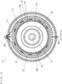
Fig. 3 is an A1-A1 illustrative sectional view of the motor inFig. 1 . -
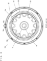
Fig. 4 is a B-B illustrative sectional view of the motor inFig. 1 . -
Fig. 5 is an axial illustrative sectional view which shows a motor unit in which a plurality of the motor inFig. 1 are axially connected. -
Fig. 6 is an illustrative side view of the motor unit inFig. 5 . -
Fig. 7 is an axial sectional view which shows a motor according to another embodiment of the present invention. -
Fig. 8 is an A2-A2 illustrative sectional view which shows the motor inFig. 7 . -
Fig. 9 is an axial sectional view which shows a motor according to still another embodiment of the present invention. -
Fig. 10 is an A3-A3 illustrative sectional view which shows the motor inFig. 9 . - Hereinafter, embodiments of the present invention will be described with reference to the drawings.
- Referring to
Fig. 1 andFig. 2 , amotor 10 according to an embodiment of the present invention is an axially connectable motor and includes ahousing 12. Inside thehousing 12, arotor 14 and astator 16 are provided. - The
rotor 14 has arotor shaft 18 and arotor core 20 provided radially outside therotor shaft 18. Therotor shaft 18 is rotatably held by thehousing 12 viabearings rotor core 20 has a plurality of magnets 26 (seeFig. 3 ).End plates rotor core 20. Also, acollar 32 is fitted around therotor shaft 18 to prevent therotor core 20 from dislodging. - The
stator 16 includes astator core 34 which is provided radially outside therotor 14 and is fixed to an inner circumferential surface of thehousing 12, and astator coil 36 which is wound around thestator core 34. Coil end covers 38, 40, 42, 44 are provided to cover two axial end portions of thestator coil 36, i.e., coil ends 36a, 36b. More specifically, referring toFig. 1 andFig. 4 , thecoil end cover 38 is provided to cover an inner circumference and an axial end portion of the plurality of coil ends 36a. Thecoil end cover 40 is provided to cover an inner circumference and an axial end portion of the plurality of coil ends 36b. Also, two coil end covers 42 are provided to cover an outer circumference of the plurality of coil ends 36a. Two coil end covers 44 are provided to cover an outer circumference of the plurality of coil ends 36b. In this arrangement, as understood fromFig. 4 , the plurality of annularly disposed coil ends 36b are covered by the two coil end covers 44 except for upper and lower regions. Likewise, the plurality of annularly disposed coil ends 36a are covered by the two coil end covers 42 except for upper and lower regions. - Referring to
Fig. 1 , thehousing 12 has two axial end portions, at which axially protrudingwall portions - At one axial end surface of the
housing 12, arecess 50 is provided. In therecess 50, a coolingmedium pump 52 is disposed which is driven by rotation of therotor shaft 18. The coolingmedium pump 52 is provided outside of thehousing 12. At least part of the coolingmedium pump 52 radially overlaps thestator coil 36. More specifically, at least part of the coolingmedium pump 52 radially overlaps thecoil end 36a. Also, with thewall portions medium pump 52 from an outer surface of thehousing 12 represented by P, a total height (H1+H2) of thewall portions medium pump 52 from the outer surface of thehousing 12. The coolingpump 52 is covered by acover 56 except for itspump shaft 54. Also, near therecess 50 of thehousing 12, through-holes Fig. 2 ) to allow cooling medium to pass through. - A
driving gear 62 is attached coaxially to therotor shaft 18 so as not to protrude axially from an end portion of therotor shaft 18. Thedriving gear 62 is driven by therotor shaft 18. A drivengear 64 is attached coaxially to the coolingmedium pump 52. The drivengear 64 has an annularouter perimeter portion 66 for engagement with thedriving gear 62, and a truncated cone-shapedinner perimeter portion 68 for attaching to the coolingmedium pump 52. The drivengear 64 is driven in engagement with thedriving gear 62, to drive the coolingmedium pump 52. - In the
housing 12, arotation sensor 70 is provided on the axially opposite side to the coolingmedium pump 52. Therotation sensor 70 is provided between thehousing 12 and therotor shaft 18 and configured as a resolver to detect a rotation angle of therotor shaft 18. Therotation sensor 70 includes aresolver stator 72 attached to thehousing 12, and aresolver rotor 74 attached to therotor shaft 18. - The
motor 10 as described thus far, is formed with a cooling medium flow path as will be described below. Themotor 10 uses oil as a cooling medium which flows through ahousing flow path 76, astator flow path 82 and arotor flow path 90 which will be described later. - Referring to
Fig. 1 andFig. 3 , thehousing flow path 76 is formed inside thehousing 12 in a circumferential direction to allow the cooling medium to flow inside thehousing 12. Thehousing flow path 76 is formed in a belt-like pattern, to radially overlap thestator core 34. Thehousing flow path 76 is supplied with the cooling medium from aninlet 78. After flowing through thehousing flow path 76, the cooling medium is discharged from anoutlet 80. Theoutlet 80 is formed wider than thehousing flow path 76 to widen in two axial sides of thehousing flow path 76. - Referring to
Fig. 1 andFig. 4 , thestator flow path 82 is formed inside thehousing 12 to supply the cooling medium to thestator 16. Thestator flow path 82 includes a plurality (two, in the present embodiment) ofinlets outlet 80 of thehousing flow path 76 at one radial side of thehousing 12; a plurality (two, in the present embodiment) ofoutlets housing 12; and a plurality (two, in the present embodiment) offlow paths stator coil 36, from theinlets outlets Fig. 4 , theinlet 84b is provided above an upper portion of the plurality of annularly disposed coil ends 36b, i.e., a portion not covered by the two coil end covers 44, to branch in three directions. Theoutlet 86b is provided below a lower portion of the plurality of annularly disposed coil ends 36b, i.e., a portion not covered by the two coil end covers 44. In other words, theinlet 84b and theoutlet 86b are provided to oppose each other with therotor shaft 18 in between. Theflow path 88b is formed in a region sandwiched by the coil end covers 40 and 44. Theinlet 84a, theoutlet 86a and theflow path 88a are formed in the same way. As described, theinlets outlet 80 of thehousing flow path 76. Theinlets stator coil 36 located there above. Theoutlets stator coil 36 located there below. Theflow path 88a provides communication between theinlet 84a and theoutlet 86a, while theflow path 88b provides communication between theinlet 84b and theoutlet 86b. Therefore, thestator flow path 82 is supplied with the cooling medium which has passed through thehousing flow path 76. After passing through thestator flow path 82, the cooling medium is discharged from theoutlets - Referring to
Fig. 1 , therotor shaft 18 is formed hollow. In order to allow the cooling medium to flow to therotor 14, therotor shaft 18 is formed with an axially penetratingrotor flow path 90. - Referring to
Fig. 5 , a motor unit 1 includes amotor 10a and a plurality (three, in the present embodiment) of themotors 10. Themotor 10a differs from themotor 10 in that it uses ahousing 12a in place of thehousing 12. Referring toFig. 5 andFig. 6 , thehousing 12a is formed with anadditional recess 50a in an axial end surface. Near therecess 50a of thehousing 12a, through-holes recess 50a of thehousing 12a is provided with a coolingmedium pump 52a for distributing the cooling medium through therotor flow path 90. Thecooling pump 52a is covered by acover 56a except for itspump shaft 54a. A drivengear 64a which is driven by thedriving gear 62 is attached to the coolingmedium pump 52a. The coolingmedium pump 52a and the drivengear 64a are configured the same way as the coolingmedium pump 52 and the drivengear 64 respectively. The drivengear 64a has an annularouter perimeter portion 66a for engagement with the driving gear 62a, and a truncated cone-shapedinner perimeter portion 68a for attaching to the coolingmedium pump 52a. All the other configurations of themotor 10a are identical with those of themotor 10. Themotor 10a which has been described thus far and the threemotors 10 are axially connected, by inserting therotor shaft 18 of one of the mutually adjacent motors into therotor shaft 18 of the other, to obtain the motor unit 1. - Referring to
Fig. 1 andFig. 5 , in the motor unit 1, at least part of therotation sensor 70 axially overlaps anouter perimeter portion 66 and radially overlaps aninner perimeter portion 68 of the drivengear 64 of theadjacent motor 10. Also, in order to ensure that theinner perimeter portion 68 of the drivengear 64 of the insertingmotor 10 is accommodated in a space S near therotation sensor 70 without being blocked by theresolver stator 72 of the receiving motor 10(10a), there is provided an amount of protrusion L of theinner perimeter portion 68 of the drivengear 64 from the surface of thedriving gear 62. - Referring to
Fig. 5 andFig. 6 , in the motor unit 1 described thus far, anoil pan 92 is disposed below each of the motors 10 (10a). In each motor 10 (10a), the cooling medium in theoil pan 92 is sucked by the coolingmedium pump 52, sent through the through-hole 58, and introduced into the coolingmedium pump 52. Then, the cooling medium inside the coolingmedium pump 52 is supplied to a respective one ofradiators 94 through the through-hole 60, cooled there, and then supplied to thehousing flow path 76 from the inlet 78 (seeFig. 3 ). After passing through thehousing flow path 76, the cooling medium goes through theoutlet 80 and theinlets stator flow path 82, into theflow paths flow paths oil pan 92 via theoutlets Fig. 1 andFig. 4 ). In this way, the cooling medium is cyclically supplied to thehousing flow path 76 and thestator flow path 82. Also, after passing through therotor flow path 90, the cooling medium is supplied to the coolingmedium pump 52a via anexternal pipe 96 and the through-hole 58a, then supplied by the coolingmedium pump 52a to aradiator 98 via the through-hole 60a, where it is cooled and then returned to therotor flow path 90. In this way, the cooling medium is cyclically supplied to therotor flow path 90. It should be noted here that althoughFig. 6 shows only oneradiator 94 in order to avoid complicating the drawing, but in reality, the radiator is provided for each motor. - As described, in the plurality of
motors housing flow paths 76 of mutually adjacent motors do not communicate with each other, i.e., thehousing flow paths 76 are independent from each other. Likewise, thestator flow paths 82 of mutually adjacent motors are independent from each other, without communicating with each other. Also, in the plurality ofmotors rotor flow paths 90 of mutually adjacent motors communicate with each other. - According to the
motor 10 as has been described thus far, at least part of the coolingmedium pump 52 which is provided in thehousing 12 radially overlaps thestator coil 36, and therefore it is possible, even when the coolingmedium pump 52 is provided, to keep an axial dimension of themotor 10 compact, making it possible to increase the space efficiency of thehousing 12. - The total height (H1 + H2) of the
wall portions medium pump 52 from the outer surface of thehousing 12. Therefore, it is possible to increase the space efficiency when axially connecting themotors 10, making it possible to connect themotors 10 without increasing an axial dimension of themotor 10. - The
driving gear 62 is attached coaxially to therotor shaft 18 so as not to protrude axially from the end portion of therotor shaft 18, while the drivengear 64 is coaxially attached to the coolingmedium pump 52. Therefore, it is possible to transmit a driving power from therotor shaft 18 to thecooling pump 52 smoothly via thedriving gear 62 and the drivengear 64 without increasing the axial dimension of themotor 10. - The
stator flow path 82 includes theinlets housing 12; theoutlets housing 12; and theflow paths inlets outlets stator coil 36. Therefore, it is possible to efficiently cool the coil ends 36a, 36b and their adjacencies by introducing the cooling medium from outside into thehousing 12 through theinlets housing 12, and to discharge the cooling medium from theoutlets housing 12. - Each of the
inlet 84a and theoutlet 86a is provided correspondingly to thecoil end 36a; each of theinlet 84b and theoutlet 86b is provided correspondingly to thecoil end 36b; theflow path 88a is formed to provide communication between theinlet 84a and theoutlet 86a; and theflow path 88b is formed to provide communication between theinlet 84b and theoutlet 86b. Therefore, it is possible to cool the coil ends 36a, 36b and their adjacencies efficiently. - The
rotor flow path 90 is formed to penetrate therotor shaft 18 axially. Therefore, it is possible to cool therotor 14, especially therotor shaft 18, efficiently with a simple configuration. - When a plurality of the
motors 10 are connected axially, therotor flow paths 90 of the mutuallyadjacent motors 10 communicate with each other. Therefore, it is possible to cool therotor 14 in eachmotor 10 efficiently with a simple configuration. - The
housing flow path 76 is formed inside thehousing 12 in a circumferential direction to radially overlap thestator core 36. Therefore, it is possible to cool inside of thehousing 12 efficiently while contributing to cooling of thestator core 36. - When a plurality of the
motors 10 are connected axially, thehousing flow paths 76 of the mutuallyadjacent motors 10 are independent from each other without communicating with each other. Therefore, it is possible to cool thehousing 12 appropriately for eachmotor 10. - In each
motor 10, theoil pan 92 and theradiator 94 can be used for dual purposes in supplying the cooling medium to thehousing flow path 76 and thestator flow path 82. - The
motor 10a also offers the functions and advantages described above for themotor 10. - Also, according to the motor unit 1 which is provided by axially connected
motors rotation sensor 70 axially overlaps theouter perimeter portion 66 of theadjacent motor 10 while radially overlapping theinner perimeter portion 68 of the drivengear 64. Therefore, it is possible, in the motor unit 1, which is provided by an axially connected plurality of themotors pump 52 and therotation sensor 70, to keep an axial dimension of the motor unit 1 compact. - Next, description will be made for a
motor 10b, which is another embodiment of the present invention, with reference toFig. 7 andFig. 8 . In themotor 10b, oil is used as the cooling medium to flow through thestator flow path 82 and therotor flow path 90 whereas water is used as the cooling medium to flow through ahousing flow path 76b (which will be described later). - The
motor 10b differs from themotor 10 in that it uses ahousing flow path 76b, aninlet 78b and anoutlet 80b in place of thehousing flow path 76, theinlet 78 and theoutlet 80, and in order to supply water to thehousing flow path 76b, an unillustrated cooling medium pump and an unillustrated radiator are used separately per motor. Differing from theoutlet 80, theoutlet 80b does not communicate with theinlets stator flow path 82 but communicates with the cooling medium pump. Therefore, after flowing through thehousing flow path 76b, the water goes to theoutlet 80b, flows through the cooling medium pump and the radiator, and then returns to thehousing flow path 76b from theinlet 78b. In this way, water is cyclically supplied to thehousing flow path 76b. Also, in themotor 10b, the oil from theradiator 94 is not supplied to thehousing flow path 76b by the coolingmedium pump 52, but is cyclically supplied to the stator flow path 82 (flow paths inlets motor 10b are identical with those in themotor 10, so no repetitive description will be repeated here. - According to the
motor 10b as has been described, it is possible to use a cooling medium appropriate to the flow path, e.g., oil to flow through thestator flow path 82 and therotor flow path 90 and water to flow through thehousing flow path 76b. - It should be noted here that the
motor 10a may also receive the same kind of modifications as have been made to change themotor 10 to themotor 10b, whereby it becomes possible to use oil for the stator flow path and the rotor flow path and use water for the housing flow path. - Further, description will be made for a
motor 10c, which is still another embodiment of the present invention, with reference toFig. 9 andFig. 10 . - The
motor 10c uses arotor 14c in place of therotor 14. Therotor 14c includes arotor shaft 18c and arotor core 20c. Therotor shaft 18c is formed hollow, and has apartition wall 100 which divides an interior thereof into an upstream side and a downstream side; a plurality of first through-holes 102 provided on the upstream side of thepartition wall 100; and a plurality of second through-holes 104 provided on the downstream side of thepartition wall 100. Therotor core 20c has a plurality ofbypass flow paths 106 for connecting each of the first through-holes 102 with a corresponding one of the second through-holes 104. In order to introduce a cooling medium to therotor 14c, arotor flow path 90c is formed from an upstream-side interior of therotor shaft 18c, through the first through-hole 102, thebypass flow path 106 and the second through-hole 104, to a downstream-side interior of therotor shaft 18c. All the other configurations of themotor 10c are identical with those in themotor 10, so no repetitive description will be repeated here. - According to the
motor 10c as has been described, it is possible to cool therotor shaft 18c and therotor core 20c of therotor 14c entirely at high efficiency. - It should be noted here that the
motor 10b may also be modified like themotor 10c, i.e., therotor shaft 18 is formed with a partition wall, first through-holes and second through-holes; therotor core 20 is formed with bypass flow paths; and a rotor flow path is formed from an upstream-side interior of therotor shaft 18 through the first through-hole, the bypass flow path and the second through-hole, to a downstream-side interior of therotor shaft 18. - In the embodiments described above, the wall portions are provided on both axial end portions of the housing. However, the present invention is not limited by this. The wall portion may be provided only on one axial end portion of the housing. In this case, it is preferable that the height of the wall portion is greater than the amount of protrusion of the cooling medium pump from the outer surface of the housing.
- Also, the cooling medium pump and the rotation sensor may be provided on a same axial side, i.e., together on one side or the other of the housing. In this case, it is possible to further decrease the axial dimension of the motor.
- The present invention being thus far described in terms of preferred embodiments, it is obvious that these may be varied in many ways within the scope and the spirit of the present invention. The scope of the present invention is only limited by the accompanied claims.
-
- 1
- Motor unit
- 10, 10a, 10b, 10c
- Motor
- 12, 12a, 12b
- Housing
- 14, 14c
- Rotor
- 16
- Stator
- 18, 18c
- Rotor shaft
- 20, 20c
- Rotor core
- 34
- Stator core
- 36
- Stator coil
- 36a, 36b
- Coil end
- 46, 48
- Wall portion
- 52, 52a
- Cooling medium pump
- 62, 62a
- Driving gear
- 64, 64a
- Driven gear
- 66, 66a
- Outer perimeter portion of driven gear
- 68, 68a
- Inner perimeter portion of driven gear
- 70
- Rotation sensor
- 76, 76b
- Housing flow path
- 78, 78b, 84a, 84b
- Inlet
- 80, 80b, 86a, 86b
- Outlet
- 82
- Stator flow path
- 88a, 88b
- Flow path
- 90, 90c
- Rotor flow path
- 100
- Partition wall
- 102
- First through-hole
- 104
- Second through-hole
- 106
- Bypass flow path
- H1, H2
- Height of wall portion
- P
- Amount of protrusion of cooling medium pump
Claims (11)
- An axially connectable motor comprising:a housing;a rotor provided inside the housing and having a rotor shaft and a rotor core provided radially outside the rotor shaft;a stator provided inside the housing and having a stator core provided radially outside the rotor and a stator coil provided in the stator core; anda cooling medium pump provided in the housing and driven by rotation of the rotor shaft, whereinat least part of the cooling medium pump radially overlaps the stator coil.
- The motor according to Claim 1, further comprising a wall portion provided on at least one of two axial end regions of the housing to protrude axially, whereinthe cooling medium pump is provided outside the housing; anda total height of the wall portion is greater than an amount of protrusion of the cooling medium pump from an outer surface of the housing.
- The motor according to Claim 1 or 2, further comprising a driving gear attached coaxially to the rotor shaft so as not to protrude axially from an end portion of the rotor shaft and driven by the rotor shaft; and
a driven gear attached coaxially to the cooling medium pump and driven by engagement with the driving gear. - The motor according to one of Claims 1 to 3, further comprising a stator flow path to introduce a cooling medium to the stator, wherein
the stator flow path includes an inlet provided on one side radially of the housing, an outlet provided on an opposing side radially of the housing, and a flow path to introduce the cooling medium from the inlet to the outlet along a coil end of the stator coil. - The motor according to Claim 4, provided with: a plurality of the inlets correspondingly to the coil end on one axial end region of the stator coil and the coil end on another axial end region of the stator coil;a plurality of the outlets correspondingly to the coil end on one axial end region of the stator coil and the coil end on another axial end region of the stator coil; anda plurality of the flow paths each providing communication between one of the inlets with a corresponding one of the outlets.
- The motor according to one of Claims 1 to 5, further comprising a rotor flow path axially penetrating the rotor shaft for the cooling medium to flow through the rotor.
- The motor according to one of Claims 1 to 5, further comprising a rotor flow path for the cooling medium to flow through the rotor, whereinthe rotor shaft is formed hollow, and has a partition wall dividing an interior thereof into an upstream side and a downstream side; a first through-hole provided on the upstream side of the partition wall; and a second through-hole provided on the downstream side of the partition wall,the rotor core has a bypass flow path for connecting the first through-hole with the second through-hole, andthe rotor flow path is formed from an upstream-side interior of the rotor shaft, through the first through-hole, the bypass flow path and the second through-hole, to a downstream-side interior of the rotor shaft.
- The motor according to Claim 6 or 7, wherein when a plurality of the motors are connected axially, the rotor flow paths of mutually adjacent motors communicate with each other.
- The motor according to one of Claims 1 to 8, further comprising a housing flow path formed inside the housing in a circumferential direction to allow the cooling medium to flow inside the housing, and radially overlapping the stator core.
- The motor according to Claim 9, wherein when a plurality of the motors are connected axially, the housing flow paths of mutually adjacent motors are independent from each other without communicating with each other.
- A motor unit obtained by axially connecting a plurality of the motors according to Claim 3, whereineach motor further includes a rotation sensor provided in the housing on an axially opposite side to the cooling medium pump;the driven gear in each motor has an annular outer perimeter portion for engagement with the driving gear, and a truncated cone-shaped inner perimeter portion for attaching to the cooling medium pump; andat least part of the rotation sensor axially overlaps the outer perimeter portion of the driven gear in the adjacent motor, and radially overlaps the inner perimeter portion thereof.
Applications Claiming Priority (2)
| Application Number | Priority Date | Filing Date | Title |
|---|---|---|---|
| JP2022089020 | 2022-05-31 | ||
| PCT/JP2023/019589 WO2023234183A1 (en) | 2022-05-31 | 2023-05-25 | Motor and motor unit |
Publications (2)
| Publication Number | Publication Date |
|---|---|
| EP4535626A1 true EP4535626A1 (en) | 2025-04-09 |
| EP4535626A4 EP4535626A4 (en) | 2025-08-27 |
Family
ID=89024922
Family Applications (1)
| Application Number | Title | Priority Date | Filing Date |
|---|---|---|---|
| EP23815940.4A Withdrawn EP4535626A4 (en) | 2022-05-31 | 2023-05-25 | ENGINE AND MOTOR UNIT |
Country Status (4)
| Country | Link |
|---|---|
| US (1) | US20250096636A1 (en) |
| EP (1) | EP4535626A4 (en) |
| JP (1) | JPWO2023234183A1 (en) |
| WO (1) | WO2023234183A1 (en) |
Family Cites Families (10)
| Publication number | Priority date | Publication date | Assignee | Title |
|---|---|---|---|---|
| JPH1169721A (en) * | 1997-08-07 | 1999-03-09 | Yaskawa Electric Corp | Core direct cooling type liquid cooling motor stator |
| DE10307566A1 (en) * | 2003-02-22 | 2004-09-02 | Linde Ag | Electrohydraulic double-pump, double-motor unit for a self-propelled work machine, especially an industrial truck |
| JP5075879B2 (en) * | 2009-06-17 | 2012-11-21 | 本田技研工業株式会社 | Electric motor |
| US8928195B2 (en) * | 2010-04-23 | 2015-01-06 | Ihi Corporation | Rotary machine |
| WO2016123507A1 (en) * | 2015-01-30 | 2016-08-04 | Prippel Technologies, Llc | Electric machine stator with liquid cooled teeth |
| WO2018030324A1 (en) * | 2016-08-09 | 2018-02-15 | 日本電産株式会社 | Drive device |
| WO2019039060A1 (en) * | 2017-08-25 | 2019-02-28 | 日本電産株式会社 | Drive device |
| US11323003B2 (en) * | 2017-10-25 | 2022-05-03 | Flowserve Management Company | Compact, modular, pump or turbine with integral modular motor or generator and coaxial fluid flow |
| EP3540918A1 (en) | 2018-03-13 | 2019-09-18 | FLET GmbH | Electric vehicle |
| US11990819B2 (en) * | 2020-11-24 | 2024-05-21 | Bosch Rexroth Corporation | Electric and hydraulic machine |
-
2023
- 2023-05-25 EP EP23815940.4A patent/EP4535626A4/en not_active Withdrawn
- 2023-05-25 JP JP2024524807A patent/JPWO2023234183A1/ja active Pending
- 2023-05-25 WO PCT/JP2023/019589 patent/WO2023234183A1/en not_active Ceased
-
2024
- 2024-11-27 US US18/962,913 patent/US20250096636A1/en active Pending
Also Published As
| Publication number | Publication date |
|---|---|
| EP4535626A4 (en) | 2025-08-27 |
| WO2023234183A1 (en) | 2023-12-07 |
| JPWO2023234183A1 (en) | 2023-12-07 |
| US20250096636A1 (en) | 2025-03-20 |
Similar Documents
| Publication | Publication Date | Title |
|---|---|---|
| US7646119B2 (en) | Electric machine with rotor cooling and corresponding cooling method | |
| EP0601751B1 (en) | Electric-motor in-line integrated hydraulic pump | |
| US7737585B2 (en) | Electric machine with improved water cooling system | |
| US9819247B2 (en) | Cooling jacket for an electric motor or generator having coolant inlet and outlets with opposite flow direction streams | |
| US8446056B2 (en) | Electric machine cooling system and method | |
| EP2749737B1 (en) | Electric pump | |
| EP4362291A1 (en) | Motor unit | |
| CN114542453B (en) | Electric and hydraulic machines | |
| EP2863522A1 (en) | Rotating electrical machine | |
| US11336138B2 (en) | Hybrid rotor module cooling | |
| CN103591019A (en) | Electrically driven dual pump | |
| CN115208130A (en) | Drive device and vehicle | |
| WO1991013256A1 (en) | Combined electric motor and pump unit | |
| US20240120798A1 (en) | Motor, motor unit, vehicle driving motor unit and electric vehicle | |
| US7367787B2 (en) | Pumping unit for a liquid medium | |
| US6215212B1 (en) | Shaftless rotor construction | |
| JP3596514B2 (en) | Cooling structure of rotating electric machine | |
| JP7668357B2 (en) | Motor and motor unit | |
| US20250096636A1 (en) | Motor and motor assembly | |
| US20060153706A1 (en) | Internal gear-wheel pump comprising reinforced channels | |
| CN116799984A (en) | Stator device with cooling system and electric machine with stator device | |
| JP2005256676A (en) | Electric pump unit | |
| US9243633B2 (en) | Device for branching off a fluidic partial flow | |
| JP2020002908A (en) | Vertical multistage pump | |
| WO2024160344A1 (en) | Electric machine with oil cooling |
Legal Events
| Date | Code | Title | Description |
|---|---|---|---|
| STAA | Information on the status of an ep patent application or granted ep patent |
Free format text: STATUS: THE INTERNATIONAL PUBLICATION HAS BEEN MADE |
|
| PUAI | Public reference made under article 153(3) epc to a published international application that has entered the european phase |
Free format text: ORIGINAL CODE: 0009012 |
|
| STAA | Information on the status of an ep patent application or granted ep patent |
Free format text: STATUS: REQUEST FOR EXAMINATION WAS MADE |
|
| 17P | Request for examination filed |
Effective date: 20241223 |
|
| AK | Designated contracting states |
Kind code of ref document: A1 Designated state(s): AL AT BE BG CH CY CZ DE DK EE ES FI FR GB GR HR HU IE IS IT LI LT LU LV MC ME MK MT NL NO PL PT RO RS SE SI SK SM TR |
|
| REG | Reference to a national code |
Ref country code: DE Ref legal event code: R079 Free format text: PREVIOUS MAIN CLASS: H02K0009190000 Ipc: H02K0001200000 |
|
| A4 | Supplementary search report drawn up and despatched |
Effective date: 20250729 |
|
| RIC1 | Information provided on ipc code assigned before grant |
Ipc: H02K 1/20 20060101AFI20250723BHEP Ipc: H02K 1/32 20060101ALI20250723BHEP Ipc: H02K 5/20 20060101ALI20250723BHEP Ipc: H02K 7/14 20060101ALI20250723BHEP Ipc: H02K 7/116 20060101ALI20250723BHEP Ipc: H02K 9/197 20060101ALI20250723BHEP Ipc: H02K 11/21 20160101ALI20250723BHEP Ipc: H02K 16/00 20060101ALI20250723BHEP |
|
| DAV | Request for validation of the european patent (deleted) | ||
| DAX | Request for extension of the european patent (deleted) | ||
| STAA | Information on the status of an ep patent application or granted ep patent |
Free format text: STATUS: THE APPLICATION HAS BEEN WITHDRAWN |
|
| 18W | Application withdrawn |
Effective date: 20250908 |