EP4535610A1 - Contactless power supply system, vehicle, and contactless power supply/receiving device - Google Patents
Contactless power supply system, vehicle, and contactless power supply/receiving device Download PDFInfo
- Publication number
- EP4535610A1 EP4535610A1 EP23815566.7A EP23815566A EP4535610A1 EP 4535610 A1 EP4535610 A1 EP 4535610A1 EP 23815566 A EP23815566 A EP 23815566A EP 4535610 A1 EP4535610 A1 EP 4535610A1
- Authority
- EP
- European Patent Office
- Prior art keywords
- power feeding
- vehicle
- power
- contact
- amount
- Prior art date
- Legal status (The legal status is an assumption and is not a legal conclusion. Google has not performed a legal analysis and makes no representation as to the accuracy of the status listed.)
- Pending
Links
Images



Classifications
-
- G—PHYSICS
- G06—COMPUTING OR CALCULATING; COUNTING
- G06Q—INFORMATION AND COMMUNICATION TECHNOLOGY [ICT] SPECIALLY ADAPTED FOR ADMINISTRATIVE, COMMERCIAL, FINANCIAL, MANAGERIAL OR SUPERVISORY PURPOSES; SYSTEMS OR METHODS SPECIALLY ADAPTED FOR ADMINISTRATIVE, COMMERCIAL, FINANCIAL, MANAGERIAL OR SUPERVISORY PURPOSES, NOT OTHERWISE PROVIDED FOR
- G06Q30/00—Commerce
- G06Q30/018—Certifying business or products
-
- B—PERFORMING OPERATIONS; TRANSPORTING
- B60—VEHICLES IN GENERAL
- B60L—PROPULSION OF ELECTRICALLY-PROPELLED VEHICLES; SUPPLYING ELECTRIC POWER FOR AUXILIARY EQUIPMENT OF ELECTRICALLY-PROPELLED VEHICLES; ELECTRODYNAMIC BRAKE SYSTEMS FOR VEHICLES IN GENERAL; MAGNETIC SUSPENSION OR LEVITATION FOR VEHICLES; MONITORING OPERATING VARIABLES OF ELECTRICALLY-PROPELLED VEHICLES; ELECTRIC SAFETY DEVICES FOR ELECTRICALLY-PROPELLED VEHICLES
- B60L15/00—Methods, circuits, or devices for controlling the traction-motor speed of electrically-propelled vehicles
- B60L15/20—Methods, circuits, or devices for controlling the traction-motor speed of electrically-propelled vehicles for control of the vehicle or its driving motor to achieve a desired performance, e.g. speed, torque, programmed variation of speed
- B60L15/2045—Methods, circuits, or devices for controlling the traction-motor speed of electrically-propelled vehicles for control of the vehicle or its driving motor to achieve a desired performance, e.g. speed, torque, programmed variation of speed for optimising the use of energy
-
- B—PERFORMING OPERATIONS; TRANSPORTING
- B60—VEHICLES IN GENERAL
- B60L—PROPULSION OF ELECTRICALLY-PROPELLED VEHICLES; SUPPLYING ELECTRIC POWER FOR AUXILIARY EQUIPMENT OF ELECTRICALLY-PROPELLED VEHICLES; ELECTRODYNAMIC BRAKE SYSTEMS FOR VEHICLES IN GENERAL; MAGNETIC SUSPENSION OR LEVITATION FOR VEHICLES; MONITORING OPERATING VARIABLES OF ELECTRICALLY-PROPELLED VEHICLES; ELECTRIC SAFETY DEVICES FOR ELECTRICALLY-PROPELLED VEHICLES
- B60L50/00—Electric propulsion with power supplied within the vehicle
- B60L50/50—Electric propulsion with power supplied within the vehicle using propulsion power supplied by batteries or fuel cells
- B60L50/53—Electric propulsion with power supplied within the vehicle using propulsion power supplied by batteries or fuel cells in combination with an external power supply, e.g. from overhead contact lines
-
- B—PERFORMING OPERATIONS; TRANSPORTING
- B60—VEHICLES IN GENERAL
- B60L—PROPULSION OF ELECTRICALLY-PROPELLED VEHICLES; SUPPLYING ELECTRIC POWER FOR AUXILIARY EQUIPMENT OF ELECTRICALLY-PROPELLED VEHICLES; ELECTRODYNAMIC BRAKE SYSTEMS FOR VEHICLES IN GENERAL; MAGNETIC SUSPENSION OR LEVITATION FOR VEHICLES; MONITORING OPERATING VARIABLES OF ELECTRICALLY-PROPELLED VEHICLES; ELECTRIC SAFETY DEVICES FOR ELECTRICALLY-PROPELLED VEHICLES
- B60L53/00—Methods of charging batteries, specially adapted for electric vehicles; Charging stations or on-board charging equipment therefor; Exchange of energy storage elements in electric vehicles
- B60L53/10—Methods of charging batteries, specially adapted for electric vehicles; Charging stations or on-board charging equipment therefor; Exchange of energy storage elements in electric vehicles characterised by the energy transfer between the charging station and the vehicle
- B60L53/12—Inductive energy transfer
-
- B—PERFORMING OPERATIONS; TRANSPORTING
- B60—VEHICLES IN GENERAL
- B60L—PROPULSION OF ELECTRICALLY-PROPELLED VEHICLES; SUPPLYING ELECTRIC POWER FOR AUXILIARY EQUIPMENT OF ELECTRICALLY-PROPELLED VEHICLES; ELECTRODYNAMIC BRAKE SYSTEMS FOR VEHICLES IN GENERAL; MAGNETIC SUSPENSION OR LEVITATION FOR VEHICLES; MONITORING OPERATING VARIABLES OF ELECTRICALLY-PROPELLED VEHICLES; ELECTRIC SAFETY DEVICES FOR ELECTRICALLY-PROPELLED VEHICLES
- B60L53/00—Methods of charging batteries, specially adapted for electric vehicles; Charging stations or on-board charging equipment therefor; Exchange of energy storage elements in electric vehicles
- B60L53/30—Constructional details of charging stations
- B60L53/32—Constructional details of charging stations by charging in short intervals along the itinerary, e.g. during short stops
-
- B—PERFORMING OPERATIONS; TRANSPORTING
- B60—VEHICLES IN GENERAL
- B60L—PROPULSION OF ELECTRICALLY-PROPELLED VEHICLES; SUPPLYING ELECTRIC POWER FOR AUXILIARY EQUIPMENT OF ELECTRICALLY-PROPELLED VEHICLES; ELECTRODYNAMIC BRAKE SYSTEMS FOR VEHICLES IN GENERAL; MAGNETIC SUSPENSION OR LEVITATION FOR VEHICLES; MONITORING OPERATING VARIABLES OF ELECTRICALLY-PROPELLED VEHICLES; ELECTRIC SAFETY DEVICES FOR ELECTRICALLY-PROPELLED VEHICLES
- B60L53/00—Methods of charging batteries, specially adapted for electric vehicles; Charging stations or on-board charging equipment therefor; Exchange of energy storage elements in electric vehicles
- B60L53/30—Constructional details of charging stations
- B60L53/35—Means for automatic or assisted adjustment of the relative position of charging devices and vehicles
- B60L53/38—Means for automatic or assisted adjustment of the relative position of charging devices and vehicles specially adapted for charging by inductive energy transfer
- B60L53/39—Means for automatic or assisted adjustment of the relative position of charging devices and vehicles specially adapted for charging by inductive energy transfer with position-responsive activation of primary coils
-
- B—PERFORMING OPERATIONS; TRANSPORTING
- B60—VEHICLES IN GENERAL
- B60L—PROPULSION OF ELECTRICALLY-PROPELLED VEHICLES; SUPPLYING ELECTRIC POWER FOR AUXILIARY EQUIPMENT OF ELECTRICALLY-PROPELLED VEHICLES; ELECTRODYNAMIC BRAKE SYSTEMS FOR VEHICLES IN GENERAL; MAGNETIC SUSPENSION OR LEVITATION FOR VEHICLES; MONITORING OPERATING VARIABLES OF ELECTRICALLY-PROPELLED VEHICLES; ELECTRIC SAFETY DEVICES FOR ELECTRICALLY-PROPELLED VEHICLES
- B60L53/00—Methods of charging batteries, specially adapted for electric vehicles; Charging stations or on-board charging equipment therefor; Exchange of energy storage elements in electric vehicles
- B60L53/60—Monitoring or controlling charging stations
- B60L53/65—Monitoring or controlling charging stations involving identification of vehicles or their battery types
-
- B—PERFORMING OPERATIONS; TRANSPORTING
- B60—VEHICLES IN GENERAL
- B60L—PROPULSION OF ELECTRICALLY-PROPELLED VEHICLES; SUPPLYING ELECTRIC POWER FOR AUXILIARY EQUIPMENT OF ELECTRICALLY-PROPELLED VEHICLES; ELECTRODYNAMIC BRAKE SYSTEMS FOR VEHICLES IN GENERAL; MAGNETIC SUSPENSION OR LEVITATION FOR VEHICLES; MONITORING OPERATING VARIABLES OF ELECTRICALLY-PROPELLED VEHICLES; ELECTRIC SAFETY DEVICES FOR ELECTRICALLY-PROPELLED VEHICLES
- B60L53/00—Methods of charging batteries, specially adapted for electric vehicles; Charging stations or on-board charging equipment therefor; Exchange of energy storage elements in electric vehicles
- B60L53/60—Monitoring or controlling charging stations
- B60L53/66—Data transfer between charging stations and vehicles
- B60L53/665—Methods related to measuring, billing or payment
-
- G—PHYSICS
- G06—COMPUTING OR CALCULATING; COUNTING
- G06Q—INFORMATION AND COMMUNICATION TECHNOLOGY [ICT] SPECIALLY ADAPTED FOR ADMINISTRATIVE, COMMERCIAL, FINANCIAL, MANAGERIAL OR SUPERVISORY PURPOSES; SYSTEMS OR METHODS SPECIALLY ADAPTED FOR ADMINISTRATIVE, COMMERCIAL, FINANCIAL, MANAGERIAL OR SUPERVISORY PURPOSES, NOT OTHERWISE PROVIDED FOR
- G06Q30/00—Commerce
- G06Q30/02—Marketing; Price estimation or determination; Fundraising
- G06Q30/0283—Price estimation or determination
- G06Q30/0284—Time or distance, e.g. usage of parking meters or taximeters
-
- G—PHYSICS
- G06—COMPUTING OR CALCULATING; COUNTING
- G06Q—INFORMATION AND COMMUNICATION TECHNOLOGY [ICT] SPECIALLY ADAPTED FOR ADMINISTRATIVE, COMMERCIAL, FINANCIAL, MANAGERIAL OR SUPERVISORY PURPOSES; SYSTEMS OR METHODS SPECIALLY ADAPTED FOR ADMINISTRATIVE, COMMERCIAL, FINANCIAL, MANAGERIAL OR SUPERVISORY PURPOSES, NOT OTHERWISE PROVIDED FOR
- G06Q30/00—Commerce
- G06Q30/04—Billing or invoicing
-
- G—PHYSICS
- G06—COMPUTING OR CALCULATING; COUNTING
- G06Q—INFORMATION AND COMMUNICATION TECHNOLOGY [ICT] SPECIALLY ADAPTED FOR ADMINISTRATIVE, COMMERCIAL, FINANCIAL, MANAGERIAL OR SUPERVISORY PURPOSES; SYSTEMS OR METHODS SPECIALLY ADAPTED FOR ADMINISTRATIVE, COMMERCIAL, FINANCIAL, MANAGERIAL OR SUPERVISORY PURPOSES, NOT OTHERWISE PROVIDED FOR
- G06Q50/00—Information and communication technology [ICT] specially adapted for implementation of business processes of specific business sectors, e.g. utilities or tourism
- G06Q50/06—Energy or water supply
-
- G—PHYSICS
- G06—COMPUTING OR CALCULATING; COUNTING
- G06Q—INFORMATION AND COMMUNICATION TECHNOLOGY [ICT] SPECIALLY ADAPTED FOR ADMINISTRATIVE, COMMERCIAL, FINANCIAL, MANAGERIAL OR SUPERVISORY PURPOSES; SYSTEMS OR METHODS SPECIALLY ADAPTED FOR ADMINISTRATIVE, COMMERCIAL, FINANCIAL, MANAGERIAL OR SUPERVISORY PURPOSES, NOT OTHERWISE PROVIDED FOR
- G06Q50/00—Information and communication technology [ICT] specially adapted for implementation of business processes of specific business sectors, e.g. utilities or tourism
- G06Q50/40—Business processes related to the transportation industry
-
- H—ELECTRICITY
- H02—GENERATION; CONVERSION OR DISTRIBUTION OF ELECTRIC POWER
- H02J—ELECTRIC POWER NETWORKS; CIRCUIT ARRANGEMENTS OR SYSTEMS FOR SUPPLYING OR DISTRIBUTING ELECTRIC POWER; SYSTEMS FOR STORING ELECTRIC ENERGY
- H02J50/00—Circuit arrangements or systems for wireless supply or distribution of electric power
- H02J50/10—Circuit arrangements or systems for wireless supply or distribution of electric power using inductive coupling
-
- H—ELECTRICITY
- H02—GENERATION; CONVERSION OR DISTRIBUTION OF ELECTRIC POWER
- H02J—ELECTRIC POWER NETWORKS; CIRCUIT ARRANGEMENTS OR SYSTEMS FOR SUPPLYING OR DISTRIBUTING ELECTRIC POWER; SYSTEMS FOR STORING ELECTRIC ENERGY
- H02J50/00—Circuit arrangements or systems for wireless supply or distribution of electric power
- H02J50/40—Circuit arrangements or systems for wireless supply or distribution of electric power using two or more transmitting or receiving devices
- H02J50/402—Circuit arrangements or systems for wireless supply or distribution of electric power using two or more transmitting or receiving devices the two or more transmitting or the two or more receiving devices being integrated in the same unit, e.g. power mats with several coils or antennas with several sub-antennas
-
- H—ELECTRICITY
- H02—GENERATION; CONVERSION OR DISTRIBUTION OF ELECTRIC POWER
- H02J—ELECTRIC POWER NETWORKS; CIRCUIT ARRANGEMENTS OR SYSTEMS FOR SUPPLYING OR DISTRIBUTING ELECTRIC POWER; SYSTEMS FOR STORING ELECTRIC ENERGY
- H02J50/00—Circuit arrangements or systems for wireless supply or distribution of electric power
- H02J50/90—Circuit arrangements or systems for wireless supply or distribution of electric power involving detection or optimisation of position, e.g. alignment
-
- B—PERFORMING OPERATIONS; TRANSPORTING
- B60—VEHICLES IN GENERAL
- B60L—PROPULSION OF ELECTRICALLY-PROPELLED VEHICLES; SUPPLYING ELECTRIC POWER FOR AUXILIARY EQUIPMENT OF ELECTRICALLY-PROPELLED VEHICLES; ELECTRODYNAMIC BRAKE SYSTEMS FOR VEHICLES IN GENERAL; MAGNETIC SUSPENSION OR LEVITATION FOR VEHICLES; MONITORING OPERATING VARIABLES OF ELECTRICALLY-PROPELLED VEHICLES; ELECTRIC SAFETY DEVICES FOR ELECTRICALLY-PROPELLED VEHICLES
- B60L2250/00—Driver interactions
- B60L2250/10—Driver interactions by alarm
-
- H—ELECTRICITY
- H02—GENERATION; CONVERSION OR DISTRIBUTION OF ELECTRIC POWER
- H02J—ELECTRIC POWER NETWORKS; CIRCUIT ARRANGEMENTS OR SYSTEMS FOR SUPPLYING OR DISTRIBUTING ELECTRIC POWER; SYSTEMS FOR STORING ELECTRIC ENERGY
- H02J2105/00—Networks for supplying or distributing electric power characterised by their spatial reach or by the load
- H02J2105/30—Networks for supplying or distributing electric power characterised by their spatial reach or by the load the load networks being external to vehicles, i.e. exchanging power with vehicles
- H02J2105/33—Networks for supplying or distributing electric power characterised by their spatial reach or by the load the load networks being external to vehicles, i.e. exchanging power with vehicles exchanging power with road vehicles
- H02J2105/37—Networks for supplying or distributing electric power characterised by their spatial reach or by the load the load networks being external to vehicles, i.e. exchanging power with vehicles exchanging power with road vehicles exchanging power with electric vehicles [EV] or with hybrid electric vehicles [HEV]
-
- H—ELECTRICITY
- H02—GENERATION; CONVERSION OR DISTRIBUTION OF ELECTRIC POWER
- H02J—ELECTRIC POWER NETWORKS; CIRCUIT ARRANGEMENTS OR SYSTEMS FOR SUPPLYING OR DISTRIBUTING ELECTRIC POWER; SYSTEMS FOR STORING ELECTRIC ENERGY
- H02J7/00—Circuit arrangements for charging or discharging batteries or for supplying loads from batteries
- H02J7/40—Circuit arrangements for charging or discharging batteries or for supplying loads from batteries characterised by the exchange of charge or discharge related data
- H02J7/42—Circuit arrangements for charging or discharging batteries or for supplying loads from batteries characterised by the exchange of charge or discharge related data with electronic devices having internal batteries, e.g. mobile phones
-
- Y—GENERAL TAGGING OF NEW TECHNOLOGICAL DEVELOPMENTS; GENERAL TAGGING OF CROSS-SECTIONAL TECHNOLOGIES SPANNING OVER SEVERAL SECTIONS OF THE IPC; TECHNICAL SUBJECTS COVERED BY FORMER USPC CROSS-REFERENCE ART COLLECTIONS [XRACs] AND DIGESTS
- Y02—TECHNOLOGIES OR APPLICATIONS FOR MITIGATION OR ADAPTATION AGAINST CLIMATE CHANGE
- Y02T—CLIMATE CHANGE MITIGATION TECHNOLOGIES RELATED TO TRANSPORTATION
- Y02T10/00—Road transport of goods or passengers
- Y02T10/60—Other road transportation technologies with climate change mitigation effect
- Y02T10/70—Energy storage systems for electromobility, e.g. batteries
-
- Y—GENERAL TAGGING OF NEW TECHNOLOGICAL DEVELOPMENTS; GENERAL TAGGING OF CROSS-SECTIONAL TECHNOLOGIES SPANNING OVER SEVERAL SECTIONS OF THE IPC; TECHNICAL SUBJECTS COVERED BY FORMER USPC CROSS-REFERENCE ART COLLECTIONS [XRACs] AND DIGESTS
- Y02—TECHNOLOGIES OR APPLICATIONS FOR MITIGATION OR ADAPTATION AGAINST CLIMATE CHANGE
- Y02T—CLIMATE CHANGE MITIGATION TECHNOLOGIES RELATED TO TRANSPORTATION
- Y02T10/00—Road transport of goods or passengers
- Y02T10/60—Other road transportation technologies with climate change mitigation effect
- Y02T10/7072—Electromobility specific charging systems or methods for batteries, ultracapacitors, supercapacitors or double-layer capacitors
-
- Y—GENERAL TAGGING OF NEW TECHNOLOGICAL DEVELOPMENTS; GENERAL TAGGING OF CROSS-SECTIONAL TECHNOLOGIES SPANNING OVER SEVERAL SECTIONS OF THE IPC; TECHNICAL SUBJECTS COVERED BY FORMER USPC CROSS-REFERENCE ART COLLECTIONS [XRACs] AND DIGESTS
- Y02—TECHNOLOGIES OR APPLICATIONS FOR MITIGATION OR ADAPTATION AGAINST CLIMATE CHANGE
- Y02T—CLIMATE CHANGE MITIGATION TECHNOLOGIES RELATED TO TRANSPORTATION
- Y02T90/00—Enabling technologies or technologies with a potential or indirect contribution to GHG emissions mitigation
- Y02T90/10—Technologies relating to charging of electric vehicles
- Y02T90/12—Electric charging stations
-
- Y—GENERAL TAGGING OF NEW TECHNOLOGICAL DEVELOPMENTS; GENERAL TAGGING OF CROSS-SECTIONAL TECHNOLOGIES SPANNING OVER SEVERAL SECTIONS OF THE IPC; TECHNICAL SUBJECTS COVERED BY FORMER USPC CROSS-REFERENCE ART COLLECTIONS [XRACs] AND DIGESTS
- Y02—TECHNOLOGIES OR APPLICATIONS FOR MITIGATION OR ADAPTATION AGAINST CLIMATE CHANGE
- Y02T—CLIMATE CHANGE MITIGATION TECHNOLOGIES RELATED TO TRANSPORTATION
- Y02T90/00—Enabling technologies or technologies with a potential or indirect contribution to GHG emissions mitigation
- Y02T90/10—Technologies relating to charging of electric vehicles
- Y02T90/14—Plug-in electric vehicles
Definitions
- Patent Literature 1 describes a non-contact power feeding system that sets a predetermined amount of money to the amount of money to be collected as power transmission starts, and corrects the amount of money to be collected based on a difference between the predetermined amount of money and a rate corresponding to the amount of power actually transmitted or the amount of power actually received by a vehicle.
- a non-contact power feeding power receiving device mounted on a vehicle capable of receiving power from a non-contact power feeding system that supplies power in a non-contact manner from a power feeding device provided on a traveling path of the vehicle to the vehicle during traveling, includes: a determination means for determining start and stop of power feeding from the power feeding device to the vehicle based on an energy balance of electrical equipment included in the vehicle; and a notification means for notifying a charging device of the non-contact power feeding system of a determination result of the determination means. Further, the charging device uses the determination result in a process of calculating a power feeding amount and an amount of money to be charged to the vehicle.
- the vehicle 2 includes a known vehicle such as a hybrid vehicle (HV), an electric vehicle (EV), a plug-in hybrid vehicle (PHV), or a fuel cell electric vehicle (FCEV), and includes a communication module capable of performing information communication via an electric communication line NW such as an Internet line network or a mobile phone line network.
- HV hybrid vehicle
- EV electric vehicle
- PSV plug-in hybrid vehicle
- FCEV fuel cell electric vehicle
- NW electric communication line network
- the vehicle 2 includes an adder 21 that calculates the sum of an input/output power amount (battery power) of a battery and an input/output power amount (motor power) of a motor, an adder 22 that calculates the sum of an output of the adder 21 and a power consumption amount (auxiliary power) of an auxiliary machine, and a comparator 23 that compares a magnitude relationship between an output (energy balance) of the adder 22 and a power feeding determination threshold and outputs a power feeding determination signal indicating that power feeding from the power feeding device 3 is performed when the output of the adder 22 is larger than the power feeding determination threshold.
- an adder 21 that calculates the sum of an input/output power amount (battery power) of a battery and an input/output power amount (motor power) of a motor
- an adder 22 that calculates the sum of an output of the adder 21 and a power consumption amount (auxiliary power) of an auxiliary machine
- a comparator 23 that compares a magnitude relationship between an output (energy balance) of the
- the motor power corresponding to an operation command for the motor may be read from a map, or a predicted regenerative power amount may be used.
- the auxiliary power instead of using a detection value, the auxiliary power may be read from the map according to on/off of the auxiliary power.
- a comparator 24 that performs power feeding determination by comparing a magnitude relationship between the electrical characteristic of the power receiving unit and the power feeding determination threshold
- a comparator 25 that performs power feeding determination by comparing a magnitude relationship between the output (energy balance) of the adder 21 and the power feeding determination threshold (value obtained by offsetting the auxiliary power), and to output the power feeding determination signal when the power feeding determination result of the comparator 24 and the power feeding determination result of the comparator 25 match.
- the power feeding device 3 includes a rectifier that rectifies a DC voltage from a system, a plurality of inverters that convert the DC voltage rectified by the rectifier into an AC voltage, and a plurality of power transmitters that transmit the AC voltage output from the plurality of inverters to the vehicle 2 side.
- the power feeding determination unit 41 determines a time (power feeding time) and a section (power feeding section) in which a power feeding operation to the vehicle 2 is performed based on the power feeding determination signal and the vehicle ID transmitted from the vehicle 2, and outputs information on the determined power feeding time and power feeding section to the charging calculation unit 42 together with the vehicle ID.
- the charging calculation unit 42 calculates a power feeding amount to the vehicle 2 based on the power feeding time and the power feeding section output from the power feeding determination unit 41, and charges a power feeding rate (rate to be charged) to a user of the vehicle 2 corresponding to the vehicle ID according to the calculated power feeding amount. As illustrated in FIGS. 7(a) to (e) , a received power amount of the vehicle 2 may be classified in advance according to the magnitude of the received power amount, and the charging calculation unit 42 may calculate the power feeding rate according to the power feeding time or the power feeding section of each class.
- an input voltage (receiving end voltage) of the rectifier may be acquired as the electrical characteristic of the power receiving unit.
- the electrical characteristic can be detected at the same detection point. Further, even in a case where the power feeding device feeds power to the vehicle in a non-contact manner, the electrical characteristic can be detected at the same detection point as in a case where the power feeding device feeds power in contact with the vehicle.
- the charging current on the output side of an AC unit is detected as the electrical characteristic of the power receiving unit
- the charging current since the charging current has a half-wave waveform passing through a small current region as illustrated in FIG. 10(a) , an input current crosses the determination threshold every cycle, and the number of times of processing increases. Therefore, as illustrated in FIG. 10(b) , it is preferable to perform peak hold processing on the charging current and then compare the charging current with the power feeding determination threshold.
- the peak hold processing may be performed after rectifying the receiving end voltage as illustrated in FIGS. 11(a) and (b) .
- the input current may be input to a filter as illustrated in FIG. 12 , and the power feeding determination may be performed using the smoothed input current (charging current) at the subsequent stage of the filter.
- the smoothed input current charging current
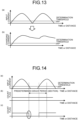
- FIG. 13(a) since the input current has a half-wave waveform passing through the small current region, the input current crosses the power feeding determination threshold every cycle, and the number of times of processing increases.
- the smoothed charging current at the subsequent stage of the filter since the number of times of crossing the power feeding determination threshold decreases as illustrated in FIG. 13(b) , it is possible to suppress an increase in the number of times of processing.
- a non-contact power feeding system capable of calculating a power feeding amount and the amount of money to be charged to the vehicle without providing a separate component.
Landscapes
- Engineering & Computer Science (AREA)
- Business, Economics & Management (AREA)
- Power Engineering (AREA)
- Mechanical Engineering (AREA)
- Transportation (AREA)
- Economics (AREA)
- Development Economics (AREA)
- Strategic Management (AREA)
- Physics & Mathematics (AREA)
- Theoretical Computer Science (AREA)
- General Physics & Mathematics (AREA)
- Marketing (AREA)
- General Business, Economics & Management (AREA)
- Accounting & Taxation (AREA)
- Finance (AREA)
- Health & Medical Sciences (AREA)
- Computer Networks & Wireless Communication (AREA)
- Primary Health Care (AREA)
- Entrepreneurship & Innovation (AREA)
- Human Resources & Organizations (AREA)
- General Health & Medical Sciences (AREA)
- Tourism & Hospitality (AREA)
- Life Sciences & Earth Sciences (AREA)
- Sustainable Development (AREA)
- Sustainable Energy (AREA)
- Game Theory and Decision Science (AREA)
- Public Health (AREA)
- Water Supply & Treatment (AREA)
- Charge And Discharge Circuits For Batteries Or The Like (AREA)
- Electric Propulsion And Braking For Vehicles (AREA)
- Management, Administration, Business Operations System, And Electronic Commerce (AREA)
Abstract
Description
- The present invention relates to a non-contact power feeding system that supplies power in a non-contact manner to a vehicle during traveling, a vehicle, and a non-contact power feeding power receiving device.
-
Patent Literature 1 describes a non-contact power feeding system that sets a predetermined amount of money to the amount of money to be collected as power transmission starts, and corrects the amount of money to be collected based on a difference between the predetermined amount of money and a rate corresponding to the amount of power actually transmitted or the amount of power actually received by a vehicle. - Patent Literature 1:
Japanese Laid-open Patent Publication No. 2014-79077 - In order to configure the non-contact power feeding system described in
Patent Literature 1, separate components such as a device for measuring the amount of power and a device for detecting the vehicle are required, and thus there is room for improvement. - The present invention has been made in view of the above problem, and an object thereof is to provide a non-contact power feeding system, a vehicle, and a non-contact power feeding power receiving device capable of calculating a power feeding amount and the amount of money to be charged to the vehicle without providing a separate component.
- A non-contact power feeding system according to the present invention that supplies power in a non-contact manner from a power feeding device provided on a traveling path of a vehicle to the vehicle during traveling, includes: a determination means for determining start and stop of power feeding from the power feeding device to the vehicle based on an energy balance of electrical equipment included in the vehicle; and a charging calculation means for calculating a power feeding amount and an amount of money to be charged to the vehicle based on a determination result of the determination means.
- A vehicle according to the present invention capable of receiving power from a non-contact power feeding system that supplies power in a non-contact manner from a power feeding device provided on a traveling path of the vehicle to the vehicle during traveling, includes: a determination means for determining start and stop of power feeding from the power feeding device to the vehicle based on an energy balance of electrical equipment included in the vehicle; and a notification means for notifying a charging device of the non-contact power feeding system of a determination result of the determination means. Further, the charging device uses the determination result in a process of calculating a power feeding amount and an amount of money to be charged to the vehicle.
- A non-contact power feeding power receiving device according to the present invention mounted on a vehicle capable of receiving power from a non-contact power feeding system that supplies power in a non-contact manner from a power feeding device provided on a traveling path of the vehicle to the vehicle during traveling, includes: a determination means for determining start and stop of power feeding from the power feeding device to the vehicle based on an energy balance of electrical equipment included in the vehicle; and a notification means for notifying a charging device of the non-contact power feeding system of a determination result of the determination means. Further, the charging device uses the determination result in a process of calculating a power feeding amount and an amount of money to be charged to the vehicle.
- Since the non-contact power feeding system, the vehicle, and the non-contact power feeding power receiving device according to the present invention determine the start and stop of power feeding from the power feeding device to the vehicle based on the energy balance of the electrical equipment included in the vehicle, it is possible to calculate the power feeding amount and the amount of money to be charged to the vehicle without providing a separate component.
-
-
FIG. 1 is a block diagram illustrating a configuration of a non-contact power feeding system according to an embodiment of the present invention. -
FIG. 2 is a circuit diagram illustrating a configuration of a vehicle illustrated inFIG. 1 . -
FIG. 3 is a diagram illustrating an energy balance of the vehicle when power feeding is not performed. -
FIG. 4 is a diagram illustrating an energy balance of the vehicle when power feeding is performed. -
FIG. 5 is a diagram for explaining a modification of power feeding determination. -
FIG. 6 is a diagram for explaining a modification of power feeding determination. -
FIG. 7 is a diagram for explaining a calculation example of a power feeding rate. -
FIG. 8 is a diagram for explaining a method of acquiring an electrical characteristic of the vehicle. -
FIG. 9 is a diagram for explaining a method of acquiring the electrical characteristic of the vehicle. -
FIG. 10 is a diagram for explaining a modification of power feeding determination. -
FIG. 11 is a diagram for explaining a modification of power feeding determination. -
FIG. 12 is a diagram for explaining a modification of power feeding determination. -
FIG. 13 is a diagram for explaining an effect according to the modification of the power feeding determination illustrated inFIG. 12 . -
FIG. 14 is a diagram for explaining a modification of power feeding determination. -
FIG. 15 is a diagram for explaining a modification of power feeding determination. -
FIG. 16 is a diagram for explaining a modification of power feeding determination. - Hereinafter, a non-contact power feeding system according to an embodiment of the present invention will be described in detail with reference to the drawings.
-
FIG. 1 is a block diagram illustrating a configuration of the non-contact power feeding system according to the embodiment of the present invention. As illustrated inFIG. 1 , the non-contactpower feeding system 1 according to the embodiment of the present invention is a system that supplies power in a non-contact manner to a vehicle during traveling, and includes a vehicle 2, apower feeding device 3, and a charging server device 4. - The vehicle 2 includes a known vehicle such as a hybrid vehicle (HV), an electric vehicle (EV), a plug-in hybrid vehicle (PHV), or a fuel cell electric vehicle (FCEV), and includes a communication module capable of performing information communication via an electric communication line NW such as an Internet line network or a mobile phone line network. In addition, as illustrated in
FIG. 2 , the vehicle 2 includes anadder 21 that calculates the sum of an input/output power amount (battery power) of a battery and an input/output power amount (motor power) of a motor, anadder 22 that calculates the sum of an output of theadder 21 and a power consumption amount (auxiliary power) of an auxiliary machine, and acomparator 23 that compares a magnitude relationship between an output (energy balance) of theadder 22 and a power feeding determination threshold and outputs a power feeding determination signal indicating that power feeding from thepower feeding device 3 is performed when the output of theadder 22 is larger than the power feeding determination threshold. Regarding the motor power, instead of using a detection value, the motor power corresponding to an operation command for the motor may be read from a map, or a predicted regenerative power amount may be used. In addition, regarding the auxiliary power, instead of using a detection value, the auxiliary power may be read from the map according to on/off of the auxiliary power. - As illustrated in
FIGS. 3(a) and (b) , the energy balance of electrical equipment included in the vehicle 2 is ±zero due to the power consumption by the electrical equipment such as the motor with respect to the power supply (discharge) from the battery. On the other hand, even when the regenerative power is returned from the motor, the battery is charged, and the energy balance of the vehicle 2 becomes ±zero. InFIG. 3(b) , illustration of the auxiliary power is omitted. On the other hand, as illustrated inFIGS. 4(a) and (b) , when power fed from the non-contactpower feeding system 1 is received via a power receiving unit, the energy balance of the electrical equipment included in the vehicle 2 swings to the positive side. Therefore, the vehicle 2 compares the magnitude relationship between the output of theadder 22 and the power feeding determination threshold using thecomparator 23, and when the output of theadder 22 is larger than the power feeding determination threshold, the vehicle 2 determines that the power feeding from thepower feeding device 3 is performed, and outputs the power feeding determination signal. Then, the vehicle 2 transmits the power feeding determination signal, via the electric communication line NW, to the charging server device 4 together with unique identification information (vehicle ID) assigned to the vehicle 2. The vehicle 2 may transmit position information (GPS signal or the like) of the vehicle 2 together with the power feeding determination signal so that it is possible to calculate a distance (power feeding section) by which the vehicle 2 moves while the power feeding determination signal is on. - It is also possible to perform the power feeding determination only by the electrical characteristic (at least one of voltage, current, and power) of an output point (before power is sent to the motor, the battery, the auxiliary machine, or the like. See
FIG. 6(a) ) of the power receiving unit. However, in this case, by disconnecting electrical wiring to which a sensor that detects the electrical characteristic of the output point is connected and providing electrical wiring that bypasses the output point, there is a possibility that fraud is performed to make it appear that power feeding is not performed although power is actually fed. Therefore, as illustrated inFIGS. 5 ,6(a), and (b) , it is preferable to provide acomparator 24 that performs power feeding determination by comparing a magnitude relationship between the electrical characteristic of the power receiving unit and the power feeding determination threshold, and acomparator 25 that performs power feeding determination by comparing a magnitude relationship between the output (energy balance) of theadder 21 and the power feeding determination threshold (value obtained by offsetting the auxiliary power), and to output the power feeding determination signal when the power feeding determination result of thecomparator 24 and the power feeding determination result of thecomparator 25 match. - Returning to
FIG. 1 , thepower feeding device 3 includes a rectifier that rectifies a DC voltage from a system, a plurality of inverters that convert the DC voltage rectified by the rectifier into an AC voltage, and a plurality of power transmitters that transmit the AC voltage output from the plurality of inverters to the vehicle 2 side. - The charging server device 4 includes an information processing device such as a workstation, and is connected to the vehicle 2 and the
power feeding device 3 via the electric communication line NW. The charging server device 4 performs information communication with the vehicle 2 and thepower feeding device 3 via the electric communication line NW. In addition, the charging server device 4 functions as a power feeding determination unit 41 and a charging calculation unit 42 when an arithmetic processing device such as a CPU inside the information processing device executes a computer program. - The power feeding determination unit 41 determines a time (power feeding time) and a section (power feeding section) in which a power feeding operation to the vehicle 2 is performed based on the power feeding determination signal and the vehicle ID transmitted from the vehicle 2, and outputs information on the determined power feeding time and power feeding section to the charging calculation unit 42 together with the vehicle ID. The charging calculation unit 42 calculates a power feeding amount to the vehicle 2 based on the power feeding time and the power feeding section output from the power feeding determination unit 41, and charges a power feeding rate (rate to be charged) to a user of the vehicle 2 corresponding to the vehicle ID according to the calculated power feeding amount. As illustrated in
FIGS. 7(a) to (e) , a received power amount of the vehicle 2 may be classified in advance according to the magnitude of the received power amount, and the charging calculation unit 42 may calculate the power feeding rate according to the power feeding time or the power feeding section of each class. - As is clear from the above description, in the non-contact
power feeding system 1 according to the embodiment of the present invention, the charging server device 4 determines the start and stop of power feeding from thepower feeding device 3 to the vehicle 2 based on the energy balance of the electrical equipment included in the vehicle 2. Therefore, it is possible to calculate the power feeding amount and the amount of money to be charged to the vehicle 2 without providing a separate component. - In a case where the power feeding device feeds power in contact with the vehicle, a current (charging current) of an interface unit between the power feeding device and the vehicle may be detected as an electrical characteristic of the power receiving unit as illustrated in
FIG. 8(a) . In addition, as illustrated inFIG. 8(b) , in a case where an element for backflow prevention such as a diode element or a switching element is disposed between the interface unit and the battery, a voltage (receiving end voltage) between the interface unit and the element may be detected as the electrical characteristic of the power receiving unit. Further, as illustrated inFIG. 8(c) , in a case where a rectifier for preventing a short circuit at the time of positive and negative reverse connection is disposed between the interface unit and the battery, an input voltage (receiving end voltage) of the rectifier may be acquired as the electrical characteristic of the power receiving unit. In addition, as illustrated inFIG. 8(d) , even when the output of the power feeding device is an AC output, the electrical characteristic can be detected at the same detection point. Further, even in a case where the power feeding device feeds power to the vehicle in a non-contact manner, the electrical characteristic can be detected at the same detection point as in a case where the power feeding device feeds power in contact with the vehicle. - As illustrated in
FIG. 9 , in a case where the charging current on the output side of an AC unit is detected as the electrical characteristic of the power receiving unit, since the charging current has a half-wave waveform passing through a small current region as illustrated inFIG. 10(a) , an input current crosses the determination threshold every cycle, and the number of times of processing increases. Therefore, as illustrated inFIG. 10(b) , it is preferable to perform peak hold processing on the charging current and then compare the charging current with the power feeding determination threshold. In a case where the receiving end voltage is detected as the electrical characteristic of the power receiving unit, the peak hold processing may be performed after rectifying the receiving end voltage as illustrated inFIGS. 11(a) and (b) . In addition, instead of performing the power feeding determination using the input current as it is, the input current may be input to a filter as illustrated inFIG. 12 , and the power feeding determination may be performed using the smoothed input current (charging current) at the subsequent stage of the filter. As illustrated inFIG. 13(a) , since the input current has a half-wave waveform passing through the small current region, the input current crosses the power feeding determination threshold every cycle, and the number of times of processing increases. On the other hand, in a case where the smoothed charging current at the subsequent stage of the filter is used, since the number of times of crossing the power feeding determination threshold decreases as illustrated inFIG. 13(b) , it is possible to suppress an increase in the number of times of processing. - As illustrated in
FIGS. 14(a) and (c) , when the counting of power feeding is stopped at the timing when the power feeding determination signal is no longer output from the vehicle 2, fine rate calculation increases, and there is a possibility that calculation data increases unnecessarily, leading to memory tightness. Therefore, as illustrated inFIG. 14(b) , in a case where the power feeding determination signal is output from the vehicle 2 within a predetermined grace period (grace section) after the power feeding determination signal is not output from the vehicle 2, the counting of the power feeding time and the power feeding section may be continued. In addition, in this case, as illustrated inFIGS. 15(a) to (c) , in a case where it is recognized that the output of the power feeding determination is stopped beyond the grace period, the power feeding rate may be calculated by going back to the time when the output of the power feeding determination signal is actually stopped. In addition, a charging opportunity loss time during the grace period may be separately counted, and a rate corresponding to the charging opportunity loss time may be subtracted at the time of calculating the power feeding rate. In addition, the unit price of the power feeding rate of the non-contactpower feeding system 1 may be determined in consideration of the charging opportunity loss time. In addition, as illustrated inFIGS. 16(a) and (b) , the unit price of the power feeding rate of the non-contactpower feeding system 1 may be determined according to a receiving power band, and the power feeding rate of the non-contactpower feeding system 1 may be calculated in consideration of how many counts are made in each receiving power band. For example, in the examples illustrated inFIGS. 16(a) and (b) , the power feeding rate of the non-contactpower feeding system 1 can be calculated as (count value of first power band × unit price of first power band power feeding rate) + (count value of second power band × unit price of second power band power feeding rate) + α. - Although the embodiment to which the invention made by the present inventors is applied has been described above, the present invention is not limited by the description and drawings constituting a part of the disclosure of the present invention according to the present embodiment. That is, other embodiments, examples, operation techniques, and the like made by those skilled in the art based on the present embodiment are all included in the scope of the present invention.
- According to the present invention, it is possible to provide a non-contact power feeding system, a vehicle, and a non-contact power feeding power receiving device capable of calculating a power feeding amount and the amount of money to be charged to the vehicle without providing a separate component.
-
- 1 NON-CONTACT POWER FEEDING SYSTEM
- 2 VEHICLE
- 3 POWER FEEDING DEVICE
- 4 CHARGING SERVER DEVICE
- 21, 22 ADDER
- 23, 24, 25 COMPARATOR
- 41 POWER FEEDING DETERMINATION UNIT
- 42 CHARGING CALCULATION UNIT
Claims (3)
- A non-contact power feeding system that supplies power in a non-contact manner from a power feeding device provided on a traveling path of a vehicle to the vehicle during traveling, the non-contact power feeding system comprising:a determination means for determining start and stop of power feeding from the power feeding device to the vehicle based on an energy balance of electrical equipment included in the vehicle; anda charging calculation means for calculating a power feeding amount and an amount of money to be charged to the vehicle based on a determination result of the determination means.
- A vehicle capable of receiving power from a non-contact power feeding system that supplies power in a non-contact manner from a power feeding device provided on a traveling path of the vehicle to the vehicle during traveling, the vehicle comprising:a determination means for determining start and stop of power feeding from the power feeding device to the vehicle based on an energy balance of electrical equipment included in the vehicle; anda notification means for notifying a charging device of the non-contact power feeding system of a determination result of the determination means, whereinthe charging device uses the determination result in a process of calculating a power feeding amount and an amount of money to be charged to the vehicle.
- A non-contact power feeding power receiving device mounted on a vehicle capable of receiving power from a non-contact power feeding system that supplies power in a non-contact manner from a power feeding device provided on a traveling path of the vehicle to the vehicle during traveling, the non-contact power feeding power receiving device comprising:a determination means for determining start and stop of power feeding from the power feeding device to the vehicle based on an energy balance of electrical equipment included in the vehicle; anda notification means for notifying a charging device of the non-contact power feeding system of a determination result of the determination means, whereinthe charging device uses the determination result in a process of calculating a power feeding amount and an amount of money to be charged to the vehicle.
Applications Claiming Priority (2)
| Application Number | Priority Date | Filing Date | Title |
|---|---|---|---|
| JP2022087816A JP7841946B2 (en) | 2022-05-30 | 2022-05-30 | Contactless power supply system, vehicle, and contactless power supply receiving device |
| PCT/JP2023/013860 WO2023233804A1 (en) | 2022-05-30 | 2023-04-03 | Contactless power supply system, vehicle, and contactless power supply/receiving device |
Publications (2)
| Publication Number | Publication Date |
|---|---|
| EP4535610A1 true EP4535610A1 (en) | 2025-04-09 |
| EP4535610A4 EP4535610A4 (en) | 2025-10-08 |
Family
ID=89026233
Family Applications (1)
| Application Number | Title | Priority Date | Filing Date |
|---|---|---|---|
| EP23815566.7A Pending EP4535610A4 (en) | 2022-05-30 | 2023-04-03 | CONTACTLESS POWER SUPPLY SYSTEM, VEHICLE AND CONTACTLESS POWER SUPPLY/RECEIVING DEVICE |
Country Status (4)
| Country | Link |
|---|---|
| EP (1) | EP4535610A4 (en) |
| JP (1) | JP7841946B2 (en) |
| CN (1) | CN119213662A (en) |
| WO (1) | WO2023233804A1 (en) |
Family Cites Families (8)
| Publication number | Priority date | Publication date | Assignee | Title |
|---|---|---|---|---|
| JPH08237890A (en) * | 1995-02-28 | 1996-09-13 | Fuji Electric Co Ltd | Non-contact power feeding device for automobile |
| JP2013073385A (en) | 2011-09-27 | 2013-04-22 | Fuji Heavy Ind Ltd | Power supply system of vehicle |
| JP5958258B2 (en) | 2012-10-10 | 2016-07-27 | トヨタ自動車株式会社 | Non-contact power supply system and control method thereof |
| JP2014102696A (en) | 2012-11-20 | 2014-06-05 | Toshiba Corp | Toll collection system and discount system using charging |
| JP6319667B2 (en) * | 2014-05-09 | 2018-05-09 | パナソニックIpマネジメント株式会社 | Power supply providing method, charge processing method, power supply system, power supply controller, power supply apparatus, power supply control method, management server, electric vehicle and charge server |
| JP2020054203A (en) | 2018-09-28 | 2020-04-02 | 株式会社Subaru | Charge management system |
| GB2580082B (en) * | 2018-12-20 | 2021-03-10 | Electric Road Ltd | Method and system for validating power metering of power over the air system for vehicles |
| JP2021083143A (en) | 2019-11-14 | 2021-05-27 | 本田技研工業株式会社 | Control device, system, vehicle, and program |
-
2022
- 2022-05-30 JP JP2022087816A patent/JP7841946B2/en active Active
-
2023
- 2023-04-03 EP EP23815566.7A patent/EP4535610A4/en active Pending
- 2023-04-03 CN CN202380040380.9A patent/CN119213662A/en active Pending
- 2023-04-03 WO PCT/JP2023/013860 patent/WO2023233804A1/en not_active Ceased
Also Published As
| Publication number | Publication date |
|---|---|
| WO2023233804A1 (en) | 2023-12-07 |
| JP2023175393A (en) | 2023-12-12 |
| JP7841946B2 (en) | 2026-04-07 |
| CN119213662A (en) | 2024-12-27 |
| EP4535610A4 (en) | 2025-10-08 |
Similar Documents
| Publication | Publication Date | Title |
|---|---|---|
| EP3089323B1 (en) | Non-contact power transmission device | |
| US9153989B2 (en) | Power monitoring system and electric vehicle | |
| US20190132719A1 (en) | Information providing system, server, and information providing method | |
| EP2685428A1 (en) | Charge service system, server, and charge service method | |
| EP2378304B1 (en) | Apparatus for calculating state of charge | |
| US9479005B2 (en) | Wireless power receiving apparatus and power control method thereof related applications | |
| US20200101865A1 (en) | Diagnosis device, diagnosis system, diagnosis method, and program | |
| CN111357168B (en) | Charging and discharging device and charging and discharging system | |
| EP2985854A1 (en) | Battery device | |
| EP3364520B1 (en) | Wireless power supply system and power transmission device | |
| US20150318708A1 (en) | Foreign Object Detection Method for Wireless Charging Systems | |
| CN106961147A (en) | Possess the Wireless power transmission system and method for overheat protective function | |
| CN103543406A (en) | Measurement system | |
| US20140062403A1 (en) | Stationary charging system | |
| CN104221251B (en) | Wireless power transmission device and its control method of wireless power signal transmission | |
| EP4535610A1 (en) | Contactless power supply system, vehicle, and contactless power supply/receiving device | |
| US11271442B2 (en) | Wireless charging prompt method and device, wireless charging system | |
| US20190152328A1 (en) | Replacement fee setting apparatus, method and system | |
| JP6551118B2 (en) | Charging apparatus and charging method | |
| JP2014150591A (en) | Battery pack for no-contact charging | |
| KR100976154B1 (en) | Non-contact charging system with charging current control function by input power | |
| KR20170000209A (en) | Apparatus for distinction pilot signal | |
| CN105048563A (en) | Charging locating method of alternating current charging post | |
| EP4535613A1 (en) | Contactless power feeding device, contactless power feeding system control program, vehicle, and contactless power feeding reception device | |
| KR102005142B1 (en) | Electric connecting device between different kind of electric device capable of user certification and information process and control system thereof |
Legal Events
| Date | Code | Title | Description |
|---|---|---|---|
| STAA | Information on the status of an ep patent application or granted ep patent |
Free format text: STATUS: THE INTERNATIONAL PUBLICATION HAS BEEN MADE |
|
| PUAI | Public reference made under article 153(3) epc to a published international application that has entered the european phase |
Free format text: ORIGINAL CODE: 0009012 |
|
| STAA | Information on the status of an ep patent application or granted ep patent |
Free format text: STATUS: REQUEST FOR EXAMINATION WAS MADE |
|
| 17P | Request for examination filed |
Effective date: 20241025 |
|
| AK | Designated contracting states |
Kind code of ref document: A1 Designated state(s): AL AT BE BG CH CY CZ DE DK EE ES FI FR GB GR HR HU IE IS IT LI LT LU LV MC ME MK MT NL NO PL PT RO RS SE SI SK SM TR |
|
| DAV | Request for validation of the european patent (deleted) | ||
| DAX | Request for extension of the european patent (deleted) | ||
| STAA | Information on the status of an ep patent application or granted ep patent |
Free format text: STATUS: EXAMINATION IS IN PROGRESS |
|
| A4 | Supplementary search report drawn up and despatched |
Effective date: 20250908 |
|
| RIC1 | Information provided on ipc code assigned before grant |
Ipc: H02J 50/40 20160101AFI20250902BHEP Ipc: B60L 5/00 20060101ALI20250902BHEP Ipc: G06Q 30/04 20120101ALI20250902BHEP Ipc: H02J 7/00 20060101ALI20250902BHEP Ipc: H02J 50/10 20160101ALI20250902BHEP Ipc: B60L 15/20 20060101ALI20250902BHEP Ipc: B60L 50/53 20190101ALI20250902BHEP Ipc: B60L 53/12 20190101ALI20250902BHEP Ipc: B60L 53/30 20190101ALI20250902BHEP Ipc: B60L 53/39 20190101ALI20250902BHEP Ipc: B60L 53/65 20190101ALI20250902BHEP Ipc: B60L 53/66 20190101ALI20250902BHEP |
|
| 17Q | First examination report despatched |
Effective date: 20250919 |
|
| GRAP | Despatch of communication of intention to grant a patent |
Free format text: ORIGINAL CODE: EPIDOSNIGR1 |
|
| STAA | Information on the status of an ep patent application or granted ep patent |
Free format text: STATUS: GRANT OF PATENT IS INTENDED |