EP4535525A1 - Housing, electrochemical apparatus, and electronic device - Google Patents
Housing, electrochemical apparatus, and electronic device Download PDFInfo
- Publication number
- EP4535525A1 EP4535525A1 EP22953584.4A EP22953584A EP4535525A1 EP 4535525 A1 EP4535525 A1 EP 4535525A1 EP 22953584 A EP22953584 A EP 22953584A EP 4535525 A1 EP4535525 A1 EP 4535525A1
- Authority
- EP
- European Patent Office
- Prior art keywords
- wall
- extension
- region
- adhesive layer
- unit
- Prior art date
- Legal status (The legal status is an assumption and is not a legal conclusion. Google has not performed a legal analysis and makes no representation as to the accuracy of the status listed.)
- Pending
Links
Images




Classifications
-
- H—ELECTRICITY
- H01—ELECTRIC ELEMENTS
- H01M—PROCESSES OR MEANS, e.g. BATTERIES, FOR THE DIRECT CONVERSION OF CHEMICAL ENERGY INTO ELECTRICAL ENERGY
- H01M50/00—Constructional details or processes of manufacture of the non-active parts of electrochemical cells other than fuel cells, e.g. hybrid cells
- H01M50/10—Primary casings; Jackets or wrappings
- H01M50/102—Primary casings; Jackets or wrappings characterised by their shape or physical structure
- H01M50/105—Pouches or flexible bags
-
- H—ELECTRICITY
- H01—ELECTRIC ELEMENTS
- H01M—PROCESSES OR MEANS, e.g. BATTERIES, FOR THE DIRECT CONVERSION OF CHEMICAL ENERGY INTO ELECTRICAL ENERGY
- H01M50/00—Constructional details or processes of manufacture of the non-active parts of electrochemical cells other than fuel cells, e.g. hybrid cells
- H01M50/10—Primary casings; Jackets or wrappings
- H01M50/183—Sealing members
- H01M50/184—Sealing members characterised by their shape or structure
-
- H—ELECTRICITY
- H01—ELECTRIC ELEMENTS
- H01M—PROCESSES OR MEANS, e.g. BATTERIES, FOR THE DIRECT CONVERSION OF CHEMICAL ENERGY INTO ELECTRICAL ENERGY
- H01M50/00—Constructional details or processes of manufacture of the non-active parts of electrochemical cells other than fuel cells, e.g. hybrid cells
- H01M50/10—Primary casings; Jackets or wrappings
- H01M50/102—Primary casings; Jackets or wrappings characterised by their shape or physical structure
-
- H—ELECTRICITY
- H01—ELECTRIC ELEMENTS
- H01M—PROCESSES OR MEANS, e.g. BATTERIES, FOR THE DIRECT CONVERSION OF CHEMICAL ENERGY INTO ELECTRICAL ENERGY
- H01M50/00—Constructional details or processes of manufacture of the non-active parts of electrochemical cells other than fuel cells, e.g. hybrid cells
- H01M50/10—Primary casings; Jackets or wrappings
- H01M50/131—Primary casings; Jackets or wrappings characterised by physical properties, e.g. gas permeability, size or heat resistance
-
- H—ELECTRICITY
- H01—ELECTRIC ELEMENTS
- H01M—PROCESSES OR MEANS, e.g. BATTERIES, FOR THE DIRECT CONVERSION OF CHEMICAL ENERGY INTO ELECTRICAL ENERGY
- H01M50/00—Constructional details or processes of manufacture of the non-active parts of electrochemical cells other than fuel cells, e.g. hybrid cells
- H01M50/10—Primary casings; Jackets or wrappings
- H01M50/131—Primary casings; Jackets or wrappings characterised by physical properties, e.g. gas permeability, size or heat resistance
- H01M50/133—Thickness
-
- H—ELECTRICITY
- H01—ELECTRIC ELEMENTS
- H01M—PROCESSES OR MEANS, e.g. BATTERIES, FOR THE DIRECT CONVERSION OF CHEMICAL ENERGY INTO ELECTRICAL ENERGY
- H01M50/00—Constructional details or processes of manufacture of the non-active parts of electrochemical cells other than fuel cells, e.g. hybrid cells
- H01M50/10—Primary casings; Jackets or wrappings
- H01M50/172—Arrangements of electric connectors penetrating the casing
-
- H—ELECTRICITY
- H01—ELECTRIC ELEMENTS
- H01M—PROCESSES OR MEANS, e.g. BATTERIES, FOR THE DIRECT CONVERSION OF CHEMICAL ENERGY INTO ELECTRICAL ENERGY
- H01M50/00—Constructional details or processes of manufacture of the non-active parts of electrochemical cells other than fuel cells, e.g. hybrid cells
- H01M50/10—Primary casings; Jackets or wrappings
- H01M50/183—Sealing members
- H01M50/186—Sealing members characterised by the disposition of the sealing members
Definitions
- the housing of some electrochemical apparatuses is made of a flexible material and includes an accommodating portion and a sealing portion extending out of a side wall of the accommodating portion.
- the accommodating portion defines an accommodating chamber for accommodating the electrode assembly and the electrolyte;
- the sealing portion is a portion for sealing the housing through a process such as thermal sealing; and the tab of the electrochemical apparatus also extends out of the housing through the sealing portion.
- the sealing portion is typically folded so as to be close to or attached to the side wall of the accommodating portion in the art.
- the sealing portion is usually provided with a notch at an outer edge corresponding to a corner of the side wall of the accommodating portion, to facilitate respective folding of portions of the sealing portion at two sides of the corner.
- the connecting wall includes a first wall unit, a second wall unit, and a third wall unit connected sequentially along an edge contour of the first wall.
- an extension direction of the first wall unit intersects with an extension direction of the third wall unit; an outer surface of the second wall unit is recessed towards the accommodating chamber; and the first wall unit, the second wall unit, and the third wall unit jointly form a recessed corner structure.
- the sealing portion includes a first extension wall, a second extension wall, and a third extension wall.
- the first extension wall includes a first region. The first region is formed by extending outwards from a surface of the first wall unit.
- the second extension wall is formed by extending outwards from a surface of the second wall unit.
- the first adhesive layer is fixedly adhered to the fourth region.
- the third region is attached and fixed to the third wall unit.
- the third region does not move relative to the accommodating portion; whereas, the fourth region is not fixed to the third wall unit and thus may move relative to the third wall unit, thus affecting the fixation strength between the third region and the third wall unit.
- the adhesion between the first adhesive layer and the fourth region can restrain the fourth region, such that a movement degree of the fourth region relative to the third region is significantly reduced or the fourth region even cannot move relatively, thereby ensuring that the overall third extension wall is maintained at a vertically disposed state for a long time and preventing the electrochemical apparatus from occupying large space.
- the fifth extension wall includes a sixth region, and the sixth region is formed by extending outwards from a surface of the fifth wall unit. In the first direction, one end of the fifth extension wall is connected to the connecting wall, and the other end of the fifth extension wall extends towards the second wall.
- the electrochemical apparatus further includes a second adhesive layer, and the second adhesive layer is disposed at the sealing portion and covers at least part of the second notch.
- a tensile strength of the first adhesive layer is ⁇ 1 and a tensile strength of the second extension wall is ⁇ 2 , where 2 ⁇ ⁇ 1 / ⁇ 2 ⁇ 10.
- Such setting allows the first adhesive layer to have a significantly higher tensile limit than the second extension wall, thereby frequently releasing the impact force for the second extension wall for a long time.
- a hardness of the first adhesive layer is H 1 and a hardness of the second extension wall is H 2 , where 1.3 ⁇ H 1 /H 2 ⁇ 10.
- a hardness of the second extension wall is H 2 , where 1.3 ⁇ H 1 /H 2 ⁇ 10.
- the sealing portion is connected to an end of the connecting wall in the first direction.
- the accommodating portion 110 when viewed in the first direction X, is L-shaped.
- the connecting wall 113 includes a first wall unit 1131, a second wall unit 1132, a third wall unit 1133, a fourth wall unit 1134, a fifth wall unit 1135, a sixth wall unit 1136, and a seventh wall unit 1137 disposed sequentially along an edge contour of the first wall 111.
- one of a sideline of the sixth wall unit 1136 extending along the second direction Y and a sideline of the fifth wall unit 1135 extending along the third direction Z forms a long side of the electrochemical apparatus 1, and the other one forms a short side of the electrochemical apparatus 1.
- the sealing portion 120 is connected to the connecting wall 113 and includes a first extension wall 121, a second extension wall 122, and a third extension wall 123.
- the first extension wall 121 includes a first region 1211.
- the first region 1211 is formed by extending from a surface of the first wall unit 1131, with one end connected to the first wall unit 1131 and the other end extending towards the second wall 112.
- the overall first region 1211 is disposed in a vertical direction as shown in FIG. 1 .
- the second extension wall 122 is formed by extending from a surface of the second wall unit 1132, with one end connected to the second wall unit 1132 and the other end extending away from the second wall unit 1132.
- the first extension wall 121 and the third extension wall 123 may be respectively folded to be attached to the connecting wall 113, thereby helping to adhere the first extension wall 121 and the third extension wall 123 to the connecting wall 113.
- the first notch 1201 when viewed in the first direction X, may alternatively run through the sealing portion 120.
- the first edge and the second edge of the sealing portion 120 enclose the first notch 1201.
- the sealing portion 120 further includes a fourth extension wall 124, a fifth extension wall 125, and a sixth extension wall 126.
- the fourth extension wall 124 extends from a surface of the fourth wall unit 1134, with one end connected to the fourth wall unit 1134 and the other end extending towards the second wall 112.
- the fifth extension wall 125 extends from a surface of the fifth wall unit 1135, with one end connected to the fifth wall unit 1135 and the other end extending towards the second wall 112.
- the sixth extension wall 126 extends from a surface of the seventh wall unit 1137, with one end connected to the seventh wall unit 1137 and the other end extending away from the seventh wall unit 1137.
- the sixth extension wall 126 is disposed substantially parallel to the first wall 111 and the second wall 112.
- the sixth extension wall 126, the first extension wall 121, the second extension wall 122, the third extension wall 123, the fourth extension wall 124, and the fifth extension wall 125 are sequentially connected to form an integrated structure.
- edges of the base shell and the cover are fixedly connected through hot melting.
- the base shell and the cover may alternatively be fixed through adhesion or the like.
- the hot melting connection method can realize fixation of the base shell and the cover without using an additional material as well as without spending time for drying an adhesive, thereby achieving higher connection efficiency.
- the housing 100 includes a multi-layer sheet.
- the multi-layer sheet specifically includes an insulating material layer (not shown in the figure), a metal material layer (not shown in the figure), and another insulating material layer (not shown in the figure) stacked sequentially.
- the multi-layer sheet includes a first portion and a second portion disposed adjacent to each other. The first portion and the second portion each include the insulating material layer, the metal material layer, and the another insulating material layer stacked sequentially. A middle region of the first portion is recessed to be totally misaligned from an edge region of the first portion in a thickness direction of the multi-layer sheet, thus forming the base shell with the concave cavity.
- the middle region of the first portion forms the cavity portion of the base shell, and the edge region of the first portion forms the flange portion of the base shell.
- the middle region of the first portion is formed through punching.
- the second portion is connected to an edge of the first portion and folded towards a side facing the concave cavity to seal the concave cavity, thus forming the housing 100 with an accommodating chamber inside, where a junction region of the second portion and the first portion is located at the sixth wall unit.
- the edges of the first portion and the second portion are correspondingly attached and fixed to form the sealing portion 120. It is worth noting that various multi-layer sheets are selected.
- the first adhesive layer 130 is disposed at the sealing portion 120, and in the thickness direction of the housing 100, a projection of the first adhesive layer 130 covers at least part of the first notch 1201 and connects the first edge and the second edge.
- the first adhesive layer 130 is disposed on a side of the second extension wall 122 facing the second wall 112. Since a distance is present between the second wall 112 and a side of the second extension wall 122 facing the second wall 112, and an outer surface of the second wall unit 1132 is recessed towards the accommodating chamber, disposing the first adhesive layer 130 on the side of the second extension wall 122 facing the second wall 112 does not additionally increase a volume occupied by the electrochemical apparatus 1. It can be understood that the first adhesive layer 130 being disposed on the side of the second extension wall 122 facing the second wall 112 is used as an example for description in this embodiment, but this application is not limited thereto.
- the first adhesive layer 130 may also be disposed on a side of the second extension wall 122 facing the first wall 111.
- the first notch 1201 may also be filled with the first adhesive layer 130.
- the adhesion between the first adhesive layer 130 and the second region 1212 can restrain the second region 1212, such that a movement degree of the second region 1212 relative to the first region 1211 is significantly reduced or the second region 1212 even cannot move relatively, thereby ensuring that the overall first extension wall 121 is maintained at a vertically disposed state for a long time as shown in FIG. 1 and preventing the electrochemical apparatus 1 from occupying large space.
- Such setting ensures that an adhesion force between the first adhesive layer 130 and the second extension wall 122 is greater than an adhesion force between the metal material layer and the insulating material layer in the sealing portion 120. Even if slippage occurs between the first adhesive layer 130 and the second extension wall 122, the slippage occurs after slippage between the metal material layer and the insulating material layer in the sealing portion 120. To be specific, a larger adhesion force is ensured between the first adhesive layer 130 and the second extension wall 122, thereby reducing the risk of separation of the first adhesive layer 130 from the second extension wall 122 during use of the electrochemical apparatus 1. Preferably, 1.2 ⁇ F 1 /F 2 ⁇ 2. The peeling force is also tested using various methods.
- the peeling force F 1 between the first adhesive layer 130 and the second extension wall 122 may be tested using the following method.
- the sealing portion 120 is adhered to a glass plate using glue, and an AL-2520 aluminum standard foil is adhered to the first adhesive layer 130 using glue, and then these materials are prepared for later use for one hour before the strength test.
- the samples and fixture are arranged to ensure that each sample is peeled along a length direction thereof at a speed of 10 mm/min, such that the sealing portion 120 is separated from the first adhesive layer 130.
- An average peeling strength of the 5 samples is obtained based on the peeling forces of the 5 samples, and is used as the peeling force between the first adhesive layer 130 and the second extension wall 122.
- the housing 100 satisfies 1.3 ⁇ H 1 /H 2 ⁇ 10, where H 1 represents a hardness of the first adhesive layer 130, and H 2 represents a hardness of the second extension wall 122. Preferably, 2 ⁇ H 1 /H 2 ⁇ 4.
- the hardness is also tested using various methods. For example, in some embodiments, the hardness of the first adhesive layer 130 is tested using the following method.
- an independent sample of the first adhesive layer 130 is obtained; then, the sample is placed on a firm plane, a D-type Shore durometer is held in a way that a press needle is at least 12 mm away from an edge of the sample and stably pressed a press leg on the sample such that the press needle is vertically pressed into the sample, and a number is read within 1s after the press leg is in full contact with the sample; and subsequently, hardness at different positions that are at least 6 mm away from a measuring point is measured 5 times, and an average value of the hardness (a micropore material is at least 15 mm away from the measuring point) is used as a hardness H 1 of the first adhesive layer 130.
- the durometer should be installed on a same model of measuring frame produced in match for measurement.
- the hardness of the second extension wall 122 is tested using the following method. First, an independent sample of the second extension wall 122 is obtained; then, the sample is placed on a firm plane, a D-type Shore durometer is held in a way that a press needle is at least 12 mm away from an edge of the sample and stably presses a press leg on the sample such that the press needle is vertically pressed into the sample, and a number is read within 1s after the press leg is in full contact with the sample; and subsequently, hardness at different positions that are at least 6 mm away from a measuring point is measured 5 times, and an average value of the hardness (a micropore material is at least 15 mm away from the measuring point) is used as a hardness H 2 of the second extension wall 122.
- the durometer should be installed on a same model
- the electrode assembly 200 is accommodated in the accommodating chamber 101 and includes a first electrode plate 210, a second electrode plate 220, and a separator 230.
- the first electrode plate 210 and the second electrode plate 220 have opposite polarities, and the separator 230 is disposed therebetween for separation.
- the first electrode plate 210 and the second electrode plate 220 are both in an L shape fitting with the shape of the housing 100, and are alternatively disposed in the first direction X.
- the separator 230 is disposed between adjacent first electrode plate 210 and second electrode plate 220.
- the tab 300 is connected to the electrode assembly 200, with one end extending out of the housing 100 through the sealing portion 120.
- the electrochemical apparatus 1 includes two tabs 300. One tab 300 is connected to the first electrode plate 210 and partially extends out of the housing 100 through the sixth extension wall 126, and the other tab 300 is connected to the second electrode plate 220 and partially extends out of the housing 100 through the sixth extension wall 126.
- the electrochemical apparatus 1 provided in some embodiments of this application includes a housing 100, an electrode assembly 200, and tabs 300.
- the housing 100 includes an accommodating portion 110, a sealing portion 120, and a first adhesive layer 130.
- the accommodating portion 110 defines an accommodating chamber 101.
- the sealing portion 120 is connected to an outer surface of the accommodating portion and is a position for sealing in the housing 100.
- An edge of the sealing portion 120 is provided with a first notch 1201.
- the first adhesive layer 130 is disposed at the sealing portion 120 and covers at least part of the first notch 1201.
- the electrochemical apparatus 1 provided in some embodiments of this application can reduce the risk that tear is likely to occur at the notch of the sealing portion 120 of the current housing 100.
- the accommodating portion 110b includes a first wall, a second wall, and a connecting wall 113b disposed therebetween.
- the first wall and the second wall are substantially U-shaped and disposed opposite each other in the first direction X, and the connecting wall 113b is disposed therebetween and are connected to the first wall and the second wall respectively.
- the connecting wall 113b includes a first wall unit 1131b, a second wall unit 1132b, a third wall unit 1133b, a fourth wall unit 1134b, a fifth wall unit 1135b, a sixth wall unit 1136b, a seventh wall unit 1137b, an eighth wall unit 1138b, a ninth wall unit 1139b, and a tenth wall unit 1130b disposed sequentially along an edge contour of the first wall.
- the first wall unit 1131b When viewed in the first direction X, the first wall unit 1131b extends along the second direction Y as shown in the figure, the third wall unit 1133b extends along the third direction Z as shown in the figure, and the fifth wall unit 1135b extends in the second direction Y as shown in the figure;
- the second wall unit 1132b connects the first wall unit 1131b and the third wall unit 1133b, with an outer surface recessed towards the accommodating chamber;
- the fourth wall unit 1134b connects the third wall unit 1133b and the fifth wall unit 1135b, with an outer surface recessed towards the accommodating chamber.
- the sealing portion 120b includes a first extension wall 121b, a second extension wall 122b, a third extension wall 123b, a fourth extension wall 124b, a fifth extension wall 125b, a sixth extension wall 126b, a seventh extension wall 127b, an eighth extension wall 128b, and a ninth extension wall 129b.
- the first extension wall 121b includes a first region 1211b, and the first region 1211b is formed by extending from a surface of the first wall unit 1131b, with one end connected to the first wall unit 1131b and the other end extending towards the second wall.
- the second extension wall 122b is formed by extending from a surface of the second wall unit 1132b, with one end connected to the second wall unit 1132b and the other end extending away from the second wall unit 1132b.
- the second extension wall 122b is disposed substantially parallel to the first wall and the second wall.
- the third extension wall 123b includes a third region 1231b, and the third region 1231b is formed by extending outwards from a surface of the third wall unit 1133b, with one end connected to the third wall unit 1133 and the other end extending towards the second wall 112.
- the fourth extension wall 124 is formed by extending from a surface of the fourth wall unit 1134, with one end connected to the fourth wall unit 1134b and the other end extending away from the fourth wall unit 1134b.
- the fourth extension wall 124b is disposed substantially parallel to the first wall and the second wall.
- the fifth extension wall 125 includes a sixth region 1251b, and the sixth region is formed by extending outwards from a surface of the fifth wall unit 1135, with one end connected to the fifth wall unit 1135 and the other end extending towards the second wall.
- the sixth extension wall 126 is formed by extending from a surface of the sixth wall unit 1136b, with one end connected to the sixth wall unit 1136b and the other end extending towards the second wall.
- the seventh extension wall 127 is formed by extending from a surface of the seventh wall unit 1137b, with one end connected to the seventh wall unit 1137b and the other end extending towards the second wall.
- the eighth extension wall 128b is formed by extending from a surface of the eighth wall unit 1138b, with one end connected to the eighth wall unit 1138b and the other end extending towards the second wall.
- the ninth extension wall 129b is formed by extending from a surface of the tenth wall unit 1130b, with one end connected to the tenth wall unit 1130b and the other end extending away from the tenth wall unit 1130.
- the ninth extension wall 129b is disposed substantially parallel to the first wall and the second wall. The tab extends out of the housing 100b through the ninth extension wall 129b.
- the second extension wall 122b is provided with a first notch 1201b.
- the first notch 1201b is disposed in a substantially same manner as the first notch 1201.
- the first extension wall 121b further includes a second region 1212b.
- the third extension wall 123b further includes a fourth region 1232b.
- the second region 1212b and the fourth region 1232b are disposed in a substantially same manner as the second region 1212 and the fourth region 1232, which is not described herein again.
- the fourth extension wall 124b is provided with a second notch 1202b.
- the second notch 1202b is located between the third extension wall 123b and the fifth extension wall 125b.
- one end of the third extension wall 123b away from the second extension wall 122b extends to the second notch 1202b, and one end of the fifth extension wall 125b also extends to the second notch 1202b.
- the provision of the second notch 1202b causes a disconnection between the third extension wall 123b and the fifth extension wall 125b.
- the third extension wall 123b and the fifth extension wall 125b may be respectively folded to be attached to the connecting wall 113b, facilitating adhesion of the third extension wall 123b and the fifth extension wall 125b to the connecting wall 113b.
- an edge of the fourth extension wall 124b away from the fourth wall unit 1134b has a third sideline connected to the third region 1231b
- an edge of the fourth extension wall 124b away from the fourth wall unit 1134b has a fourth sideline connected to the sixth region 1251b
- the third extension wall 123b further includes a fifth region 1233b.
- the second region 1233b is formed by extending from the third sideline, with one end connected to the third sideline of the fourth extension wall and the other end extending towards the second wall.
- the fifth region 1233b and the third region 1231b form an integrated structure.
- the fifth extension wall 125b further includes a seventh region 1252b.
- the seventh region 1252b is formed by extending from the fourth sideline, with one end connected to the fourth sideline of the fourth extension wall and the other end extending towards the second wall.
- the seventh region 1232 and the sixth region 1231 form an integrated structure.
- the first notch 1201 is located between the fifth region 1233 and the seventh region 1252.
- the second adhesive layer 140b is disposed on the fourth extension wall 124b and covers at least part of the second notch 1202.
- the second adhesive layer 140 on the fourth extension wall 124b For specific arrangement of the second adhesive layer 140 on the fourth extension wall 124b, reference is made to the arrangement manner of the first adhesive layer 130 on the second extension wall 122, which is not described herein again.
- the sealing portion 120b of the housing 100b is provided with two notches, which are the first notch 1201b and the second notch 1202b.
- the first adhesive layer 130b covers at least part of the first notch 1201b
- the second adhesive layer 140b covers at least part of the second notch 1202b.
- the impact force received by the second extension wall 122b and the fourth extension wall 124b is accordingly reduced, thereby reducing the risk of the second extension wall 122b and the fourth extension wall 124b being torn.
- the electrochemical apparatus 1 provided in some embodiments of this application can reduce the risk that tear is likely to occur at the notch of the sealing portion 120b of the current housing 100b.
- this application further provides a housing, where the housing the same structure as the housing in the foregoing embodiments, which is not described herein again.
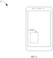
- FIG. 6 is a schematic diagram of the electronic device 2.
- the electronic device 2 includes the electrochemical apparatus 1 (or 1b) described in any of the foregoing embodiments.
- the electronic device is a mobile phone. It can be understood that in other embodiments of this application, the electronic device may alternatively be any other electronic device such as a tablet, a computer, a drone, a remote control, or an electric vehicle.
Landscapes
- Chemical & Material Sciences (AREA)
- Chemical Kinetics & Catalysis (AREA)
- Electrochemistry (AREA)
- General Chemical & Material Sciences (AREA)
- Sealing Battery Cases Or Jackets (AREA)
Abstract
Description
- This application relates to the field of battery technologies, in particular, to a housing, an electrochemical apparatus, and an electronic device.
- At present, electrochemical apparatuses are widely used in electronic devices such as mobile phones, tablets, and notebook computers to provide power for corresponding electronic products. An electrochemical apparatus includes a housing, an electrode assembly, a tab, and an electrolyte. The electrode assembly includes a first electrode plate and a second electrode plate having opposite polarities, and a separator disposed between the first electrode plate and the second electrode plate. The tab is connected to the electrode assembly and partially extends out of the housing to form a conductive terminal of the electrochemical apparatus.
- The housing of some electrochemical apparatuses is made of a flexible material and includes an accommodating portion and a sealing portion extending out of a side wall of the accommodating portion. The accommodating portion defines an accommodating chamber for accommodating the electrode assembly and the electrolyte; the sealing portion is a portion for sealing the housing through a process such as thermal sealing; and the tab of the electrochemical apparatus also extends out of the housing through the sealing portion. To reduce space occupied by the electrochemical apparatus, the sealing portion is typically folded so as to be close to or attached to the side wall of the accommodating portion in the art.
- For a housing with a square, L-shaped, or U-shaped accommodating portion, the sealing portion is usually provided with a notch at an outer edge corresponding to a corner of the side wall of the accommodating portion, to facilitate respective folding of portions of the sealing portion at two sides of the corner.
- The inventors of this application have found in implementation of this application that electrochemical apparatuses often face scenarios where drop happens, and the provision of the foregoing notch makes the sealing portion of the housing prone to tearing at the notch, which may in turn cause electrolyte leakage of the electrochemical apparatus.
- In view of the above problems in the prior art, this application is intended to provide a housing, an electrochemical apparatus, and an electronic device, to improve a current situation that a portion of a current sealing portion at the notch is likely to be torn.
- According to a first aspect, this application provides a housing. The housing includes an accommodating portion and a sealing portion. The accommodating portion defines an accommodating chamber. The sealing portion is connected to an outer surface of the accommodating portion. The housing includes a first adhesive layer. An edge of the sealing portion is provided with a first notch, and the first notch has a first edge and a second edge. The first adhesive layer is disposed at the sealing portion, and in a thickness direction of the housing, a projection of the first adhesive layer covers at least part of the first notch and connects the first edge and the second edge. In some embodiments, the first edge and the second edge enclose the first notch.
- When a second extension wall receives an impact, part of an impact force is transferred to the first adhesive layer and is released via the first adhesive layer. Thus, the impact force received by the second extension wall is accordingly reduced, thereby reducing the risk of the second extension wall being torn. To be specific, the housing provided in some embodiments of this application can reduce the risk that tear is likely to occur at the notch of the sealing portion of the current housing. In some embodiments, when viewed in the first direction, the first notch runs through the sealing portion. The use of this solution can also reduce the risk of continued inward tearing at the notch, thereby preventing electrolyte leakage.
- In some embodiments, the accommodating portion includes a first wall, a second wall, and a connecting wall. The first wall and the second wall are disposed opposite each other in a first direction. The connecting wall connects the first wall and the second wall. The first wall, the second wall, and the connecting wall jointly enclose the accommodating chamber. The sealing portion is connected to the connecting wall. The first direction is the thickness direction of the housing.
- In some embodiments, the connecting wall includes a first wall unit, a second wall unit, and a third wall unit connected sequentially along an edge contour of the first wall. When viewed in the thickness direction, an extension direction of the first wall unit intersects with an extension direction of the third wall unit; an outer surface of the second wall unit is recessed towards the accommodating chamber; and the first wall unit, the second wall unit, and the third wall unit jointly form a recessed corner structure. The sealing portion includes a first extension wall, a second extension wall, and a third extension wall. The first extension wall includes a first region. The first region is formed by extending outwards from a surface of the first wall unit. The second extension wall is formed by extending outwards from a surface of the second wall unit. An edge of the second extension wall is provided with the first notch. The third extension wall includes a third region. The third region is formed by extending outwards from a surface of the third wall unit. In the first direction, one end of the first extension wall and one end of the third extension wall are respectively connected to the connecting wall, and the other end of the first extension wall and the other end of the third extension wall extend towards the second wall.
- In some embodiments, an edge of the second extension wall away from the second wall unit has a first sideline connected to the first region, the first extension wall further includes a second region connected to the first region, and the second region extends from the first sideline towards the second wall. An edge of the second extension wall away from the second wall unit has a second sideline connected to the third region, the third extension wall further includes a fourth region connected to the third region, and the fourth region extends from the second sideline towards the second wall.
- In some embodiments, the first adhesive layer is fixedly adhered to the second region. The first region is attached and fixed to the first wall unit. During transportation, assembly, and use of the electrochemical apparatus, the first region does not move relative to the accommodating portion; whereas, the second region is not fixed to the first wall unit and thus may move relative to the first wall unit, thus affecting the fixation strength between the first region and the first wall unit. The adhesion between the first adhesive layer and the second region can restrain the second region, such that a movement degree of the second region relative to the first region is significantly reduced or the second region even cannot move relatively, thereby ensuring that the overall first extension wall is maintained at a vertically disposed state for a long time and preventing the electrochemical apparatus from occupying large space.
- In some embodiments, the first adhesive layer is fixedly adhered to the fourth region. The third region is attached and fixed to the third wall unit. During transportation, assembly, and use of the electrochemical apparatus, the third region does not move relative to the accommodating portion; whereas, the fourth region is not fixed to the third wall unit and thus may move relative to the third wall unit, thus affecting the fixation strength between the third region and the third wall unit. The adhesion between the first adhesive layer and the fourth region can restrain the fourth region, such that a movement degree of the fourth region relative to the third region is significantly reduced or the fourth region even cannot move relatively, thereby ensuring that the overall third extension wall is maintained at a vertically disposed state for a long time and preventing the electrochemical apparatus from occupying large space.
- In some embodiments, the first adhesive layer is fixedly adhered to the second wall unit. Since the second wall unit is made of a flexible material, the connection between the second wall unit and the first adhesive layer allows the second wall unit to release more of an impact force when the first adhesive layer receives the impact force, thereby reducing the risk of the first adhesive layer and the second extension wall being torn.
- In some embodiments, the first notch is filled with the first adhesive layer.
- In some embodiments, when viewed in the first direction, the first adhesive layer is circular, elliptic, or fan-shaped.
- In some embodiments, the connecting wall includes a third wall unit, a fourth wall unit, and a fifth wall unit connected sequentially along the edge contour of the first wall. When viewed in the first direction, an extension direction of the third wall unit intersects with an extension direction of the fifth wall unit; an outer surface of the fourth wall unit is recessed towards the accommodating chamber; and the third wall unit, the fourth wall unit, and the fifth wall unit jointly form a recessed corner structure. The sealing portion further includes a fourth extension wall and a fifth extension wall. The fourth extension wall is formed by extending outwards from a surface of the fourth wall unit. An edge of the fourth extension wall is provided with a second notch. The fifth extension wall includes a sixth region, and the sixth region is formed by extending outwards from a surface of the fifth wall unit. In the first direction, one end of the fifth extension wall is connected to the connecting wall, and the other end of the fifth extension wall extends towards the second wall. The electrochemical apparatus further includes a second adhesive layer, and the second adhesive layer is disposed at the sealing portion and covers at least part of the second notch.
- In some embodiments, an edge of the fourth extension wall away from the fourth wall unit has a third sideline connected to the third region, the third extension wall further includes a fifth region, and the fifth region extends from the third sideline towards the second wall. An edge of the fourth extension wall away from the fourth wall unit has a fourth sideline connected to the sixth region, the fifth extension wall further includes a seventh region, and the seventh region extends from the fourth sideline towards the second wall.
- In some embodiments, when viewed in the first direction, the accommodating portion is L-shaped or U-shaped.
- In some embodiments, a tensile strength of the first adhesive layer is σ1 and a tensile strength of the second extension wall is σ2, where 2 ≤ σ1/σ2 ≤ 10. Such setting allows the first adhesive layer to have a significantly higher tensile limit than the second extension wall, thereby frequently releasing the impact force for the second extension wall for a long time. Preferably, 3 ≤ σ1/σ2 ≤ 4.
- In some embodiments, a peeling force between the first adhesive layer and the second extension wall is F1. The sealing portion includes a metal material layer and an insulating material layer disposed on a surface of the metal material layer, the first adhesive layer is disposed on a surface of the insulating material layer, and a peeling force between the metal material layer and the insulating material layer is F2, where 1.2 ≤ F1/F2 ≤ 10. Such setting ensures that an adhesion force between the first adhesive layer and the second extension wall is greater than an adhesion force between the metal material layer and the insulating material layer in the sealing portion. Even if slippage occurs between the first adhesive layer and the second extension wall, the slippage happens after slippage between the metal material layer and the insulating material layer in the sealing portion. To be specific, a larger adhesion force is ensured between the first adhesive layer and the second extension wall, thereby reducing the risk of separation of the first adhesive layer from the second extension wall during use of the electrochemical apparatus. Preferably, 1.2 ≤ F1/F2 ≤ 2.
- In some embodiments, a hardness of the first adhesive layer is H1 and a hardness of the second extension wall is H2, where 1.3 ≤ H1/H2 ≤ 10. Preferably, 2 ≤ H1/H2 ≤ 4.
- In some embodiments, the sealing portion is connected to an end of the connecting wall in the first direction.
- According to a second aspect, this application further provides an electrochemical apparatus, where the electrochemical apparatus includes the foregoing housing.
- With the foregoing housing, the electrochemical apparatus can reduce the risk that tear is likely to occur at the notch of the sealing portion of the current housing.
- According to a third aspect, this application further provides an electronic device, where the electronic device includes the foregoing electrochemical apparatus. With the foregoing housing, the electronic device can reduce the risk that tear is likely to occur at the notch of the sealing portion of the current housing.
- One or more embodiments are used as examples for description by using corresponding accompanying drawings. These example descriptions impose no limitation on some embodiments. Elements with a same reference sign in the accompanying drawings represent similar elements. Unless otherwise stated, the figures in the accompanying drawings impose no limitation on a scale.
-
FIG. 1 is a schematic diagram of an electrochemical apparatus according to an embodiment of this application; -
FIG. 2 is a schematic cross-sectional view of the electrochemical apparatus inFIG. 1 along line A-A; -
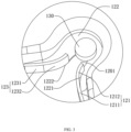
FIG. 3 is a schematic locally enlarged view of a location B inFIG. 1 ; -
FIG. 4 is a schematic locally enlarged view of a location C inFIG. 2 ; -
FIG. 5 is a schematic diagram of an electrochemical apparatus according to another embodiment of this application; and -
FIG. 6 is a schematic diagram of an electronic device according to an embodiment of this application. - For ease of understanding this application, the following makes a more detailed description of this application with reference to the accompanying drawings and specific embodiments. It should be noted that when an element is referred to as being "fixed to", "fastened to", or "mounted to" another element, it may be directly fixed to the another element, or there may be one or more elements therebetween. When an element is referred to as being "connected to" another element, it may be directly connected to the another element, or there may be one or more elements therebetween. The terms "perpendicular", "horizontal", "left", "right", "inside", "outside", and similar expressions used in this specification are merely for description purposes.
- Unless otherwise defined, all technical and scientific terms used in this specification shall have the same meanings as commonly understood by persons skilled in the art to which this application belongs. The terms used in the specification of this application are merely for description of specific embodiments rather than for limiting this application. The term "and/or" used in this specification includes any and all combinations of one or more associated items listed.
- In addition, technical features involved in different embodiments of this application that are described below may be combined as long as they do not conflict with each other.
- Reference is made to
FIG. 1 to FIG. 4 , whereFIG. 1 to FIG. 4 are respectively a schematic diagram of anelectrochemical apparatus 1 according to an embodiment of this application, a schematic cross-sectional view of theelectrochemical apparatus 1 along line A-A, a schematic locally enlarged view of a location A, and a schematic locally enlarged view of a location B. Theelectrochemical apparatus 1 includes ahousing 100, anelectrode assembly 200, and atab 300. Thehousing 100 is a mounting base and container for the other components of theelectrochemical apparatus 1. Theelectrode assembly 200 is accommodated in thehousing 100 and is a core component of theelectrochemical apparatus 1 for implementing charge and discharge. One end of thetab 300 is connected to theelectrode assembly 200, and the other end extends out of thehousing 100 to be connected to an electrical load outside theelectrochemical apparatus 1. Subsequently, theelectrochemical apparatus 1 being a lithium-ion battery is used as an example for describing a specific structure of theelectrochemical apparatus 1. It should be understood that in other embodiments of this application, theelectrochemical apparatus 1 may alternatively be an electrochemical apparatus in another form, for example, a sodium-ion battery. - For the
housing 100, reference is specifically made toFIG. 2 . Thehousing 100 is made of a flexible material and constitutes the mounting base, container, and outer protective structure of theelectrochemical apparatus 1. Thehousing 100 includes anaccommodating portion 110 and a sealingportion 120. Theaccommodating portion 110 defines anaccommodating chamber 101 for accommodating theelectrode assembly 200, electrolyte, and part of thetab 300. The sealingportion 120 is connected to an outer surface of theaccommodating portion 110, and is a sealing position formed through stacking and compositing in a hot melting manner, an adhesion manner, or the like in thehousing 100. - The
accommodating portion 110 includes afirst wall 111, asecond wall 112, and a connectingwall 113. Thefirst wall 111 and thesecond wall 112 are basically the same in shape and are disposed opposite each other in a first direction X. The connectingwall 113 is located between thefirst wall 111 and thesecond wall 112 and is connected to thefirst wall 111 and thesecond wall 112 respectively. Thefirst wall 111, thesecond wall 112, and the connectingwall 113 jointly enclose theaccommodating chamber 101. In the specification of this application, the "first direction" refers to a thickness direction of thehousing 100. - Reference is specifically made to
FIG. 1 . In this embodiment, when viewed in the first direction X, theaccommodating portion 110 is L-shaped. Correspondingly, the connectingwall 113 includes afirst wall unit 1131, a second wall unit 1132, athird wall unit 1133, afourth wall unit 1134, afifth wall unit 1135, asixth wall unit 1136, and aseventh wall unit 1137 disposed sequentially along an edge contour of thefirst wall 111. When viewed in the first direction X, thefirst wall unit 1131 extends along a second direction Y shown in the figure; the second direction Y is perpendicular to the first direction X; thethird wall unit 1133 extends along a third direction Z shown in the figure; and the third direction Z is perpendicular to both the first direction X and the second direction Y. The extension direction of thefirst wall unit 1131 intersects with the extension direction of thethird wall unit 1133, and the second wall unit 1132 connects thefirst wall unit 1131 and thethird wall unit 1133. When viewed in the first direction X, an outer surface of the second wall unit 1132 is recessed towards theaccommodating chamber 101, for example, is a concave arc as shown inFIG. 1 . Thefirst wall unit 1131, the second wall unit 1132, and thethird wall unit 1133 jointly form a recessed corner structure. - The
fourth wall unit 1134 and thesixth wall unit 1136 also extend along the second direction Y shown in the figure and are respectively disposed on two sides of thefirst wall unit 1131. Thefifth wall unit 1135 and theseventh wall unit 1137 extend along the third direction Z shown in the figure and are respectively disposed on two sides of thethird wall unit 1133. A length of thesixth wall unit 1136 is greater than lengths of thefirst wall unit 1131 and thefourth wall unit 1134. A length of thefifth wall unit 1135 is greater than lengths of thethird wall unit 1133 and theseventh wall unit 1137. Thus, one of a sideline of thesixth wall unit 1136 extending along the second direction Y and a sideline of thefifth wall unit 1135 extending along the third direction Z forms a long side of theelectrochemical apparatus 1, and the other one forms a short side of theelectrochemical apparatus 1. - For the sealing
portion 120, reference is made toFIG. 1 andFIG. 3 . The sealingportion 120 is connected to the connectingwall 113 and includes afirst extension wall 121, asecond extension wall 122, and athird extension wall 123. Thefirst extension wall 121 includes afirst region 1211. Thefirst region 1211 is formed by extending from a surface of thefirst wall unit 1131, with one end connected to thefirst wall unit 1131 and the other end extending towards thesecond wall 112. To be specific, the overallfirst region 1211 is disposed in a vertical direction as shown inFIG. 1 . Thesecond extension wall 122 is formed by extending from a surface of the second wall unit 1132, with one end connected to the second wall unit 1132 and the other end extending away from the second wall unit 1132. Thesecond extension wall 122 is disposed substantially parallel to thefirst wall 111 and thesecond wall 112. Thethird extension wall 123 includes athird region 1231. Thethird region 1231 is formed by extending outwards from a surface of thethird wall unit 1133, with one end connected to thethird wall unit 1133 and the other end extending towards thesecond wall 112. To be specific, the overallthird region 1231 is disposed in a vertical direction as shown inFIG. 1 . - An edge of the
second extension wall 122 away from the second wall unit 1132 is provided with afirst notch 1201. Thefirst notch 1201 is located between thefirst extension wall 121 and thethird extension wall 123, and thefirst notch 1201 has a first edge and a second edge. When viewed in the first direction X, one end of thefirst extension wall 121 extends to thefirst notch 1201, and one end of thethird extension wall 123 also extends to thefirst notch 1201. The provision of thefirst notch 1201 causes a disconnection between thefirst extension wall 121 and thethird extension wall 123. Thus, during folding of the sealingportion 120, thefirst extension wall 121 and thethird extension wall 123 may be respectively folded to be attached to the connectingwall 113, thereby helping to adhere thefirst extension wall 121 and thethird extension wall 123 to the connectingwall 113. In some embodiments, when viewed in the first direction X, thefirst notch 1201 may alternatively run through the sealingportion 120. In some embodiments, the first edge and the second edge of the sealingportion 120 enclose thefirst notch 1201. - In this embodiment, an edge of the
second extension wall 122 away from the second wall unit 1132 has afirst sideline 1221 connected to thefirst region 1211, and an edge of thesecond extension wall 122 away from the second wall unit 1132 has asecond sideline 1222 connected to thethird region 1231. Correspondingly, thefirst extension wall 121 further includes asecond region 1212. Thesecond region 1212 is formed by extending from thefirst sideline 1221, with one end connected to thefirst sideline 1221 of the second extension wall and the other end extending towards thesecond wall 112. Thesecond region 1212 and thefirst region 1211 form an integrated structure. When viewed in the first direction X, one end of thefirst extension wall 121 is connected to the connectingwall 113, and the other end extends towards thesecond wall 112. Thethird extension wall 123 further includes afourth region 1232. Thefourth region 1232 is formed by extending from thesecond sideline 1222, with one end connected to thesecond sideline 1222 of the second extension wall and the other end extending towards thesecond wall 112. Thefourth region 1232 and thethird region 1231 form an integrated structure. To be specific, thefirst notch 1201 is located between thesecond region 1212 and thefourth region 1232. - In addition, in this embodiment, the sealing
portion 120 further includes afourth extension wall 124, afifth extension wall 125, and asixth extension wall 126. Specifically, reference is still made toFIG. 1 . Thefourth extension wall 124 extends from a surface of thefourth wall unit 1134, with one end connected to thefourth wall unit 1134 and the other end extending towards thesecond wall 112. Thefifth extension wall 125 extends from a surface of thefifth wall unit 1135, with one end connected to thefifth wall unit 1135 and the other end extending towards thesecond wall 112. Thesixth extension wall 126 extends from a surface of theseventh wall unit 1137, with one end connected to theseventh wall unit 1137 and the other end extending away from theseventh wall unit 1137. Thesixth extension wall 126 is disposed substantially parallel to thefirst wall 111 and thesecond wall 112. Thesixth extension wall 126, thefirst extension wall 121, thesecond extension wall 122, thethird extension wall 123, thefourth extension wall 124, and thefifth extension wall 125 are sequentially connected to form an integrated structure. - In this embodiment, the electrochemical apparatus further includes a second adhesive layer. Specifically, at least one of the
first region 1211, thethird region 1211, thefourth extension wall 124, thefifth extension wall 125, or thesixth extension wall 126 is adhered to theaccommodating portion 110 through the second adhesive layer. - To facilitate a better understanding of the
housing 100, the following provides a brief description of a manufacturing process of thehousing 100. - In this embodiment, the
electrochemical apparatus 1 is a pouch battery, and thehousing 100 includes a base shell and a cover disposed facing each other. The base shell is a topless box structure, including a cavity portion and a flange portion. The cavity portion is provided with an L-shaped concave cavity with one end open. The cavity portion extends outwards from an edge of the concave cavity to form the flange portion. To be specific, the flange portion extends around the open end of the cavity portion. The cover faces the concave cavity. An edge of the cover is fixedly attached to the flange portion to form the sealingportion 120 which seals the concave cavity. Thus, a portion of thehousing 100 outside the sealing portion forms theaccommodating portion 110 of thehousing 100. Preferably, edges of the base shell and the cover are fixedly connected through hot melting. Certainly, in other embodiments of this application, the base shell and the cover may alternatively be fixed through adhesion or the like. However, compared with adhesion, the hot melting connection method can realize fixation of the base shell and the cover without using an additional material as well as without spending time for drying an adhesive, thereby achieving higher connection efficiency. - In this embodiment, the base shell and the cover are integrated. Specifically, the
housing 100 includes a multi-layer sheet. The multi-layer sheet specifically includes an insulating material layer (not shown in the figure), a metal material layer (not shown in the figure), and another insulating material layer (not shown in the figure) stacked sequentially. More specifically, the multi-layer sheet includes a first portion and a second portion disposed adjacent to each other. The first portion and the second portion each include the insulating material layer, the metal material layer, and the another insulating material layer stacked sequentially. A middle region of the first portion is recessed to be totally misaligned from an edge region of the first portion in a thickness direction of the multi-layer sheet, thus forming the base shell with the concave cavity. To be specific, the middle region of the first portion forms the cavity portion of the base shell, and the edge region of the first portion forms the flange portion of the base shell. Optionally, the middle region of the first portion is formed through punching. The second portion is connected to an edge of the first portion and folded towards a side facing the concave cavity to seal the concave cavity, thus forming thehousing 100 with an accommodating chamber inside, where a junction region of the second portion and the first portion is located at the sixth wall unit. The edges of the first portion and the second portion are correspondingly attached and fixed to form the sealingportion 120. It is worth noting that various multi-layer sheets are selected. For example, in some embodiments, the metal material layer is made of aluminum foil, one insulating material layer is made of polyethylene terephthalate, and the another insulating material layer is made of polyethylene. For another example, in some other embodiments, the metal material layer is still made of aluminum foil, and the two insulating material layers are both made of polyethylene terephthalate. For still another example, in still some other embodiments, the metal material layer is still made of aluminum foil, and the two insulating material layers are both made of a mixture of polyethylene terephthalate and polyethylene. The structure of the multi-layer sheet is not specifically limited in this application. Certainly, in other embodiments of this application, the base shell and the cover can alternatively be two separate structures that are stacked and fixed through hot melting or adhesion. Correspondingly, the sealing portion further includes a seventh extension wall formed by extending from the sixth wall unit. - It is worth noting that the provision of the
first notch 1201 facilitates the folding of thefirst extension wall 121 and thethird extension wall 123, but the provision also makes the sealingportion 120 relatively weak at this position. When theelectrochemical apparatus 1 or an electronic device provided with theelectrochemical apparatus 1 drops accidentally, the sealingportion 120 is likely to be further torn on the basis of thefirst notch 1201. If the tear extends to the second wall unit 1132, thehousing 100 may be broken due to the tear, leading to electrolyte leakage or allowing moisture and dust to enter thehousing 100, and thus causing a failure in normal work of theelectrochemical apparatus 1. To reduce the above risk, thehousing 100 further includes a firstadhesive layer 130. The firstadhesive layer 130 is disposed at the sealingportion 120, and in the thickness direction of thehousing 100, a projection of the firstadhesive layer 130 covers at least part of thefirst notch 1201 and connects the first edge and the second edge. Thus, when thesecond extension wall 122 receives an impact, part of an impact force is transferred to the firstadhesive layer 130 and is released via the firstadhesive layer 130, such that the impact force received by thesecond extension wall 122 is reduced to reduce the risk of thesecond extension wall 122 being torn, thereby reducing the risk of thehousing 100 being broken. - In this embodiment, when viewed in the first direction X, the
first notch 1201 has a first side close to thefirst extension wall 121 and a second side close to thethird extension wall 123; the first side and the second side are disposed opposite each other; and the firstadhesive layer 130 covers both at least part of the first side and at least part of the second side. Thus, thefirst notch 1201 divides thesecond extension wall 122 into two portions on two sides of thefirst notch 1201, but the firstadhesive layer 130 adheres the two portions to each other, making the two portions unlikely to be further torn before the firstadhesive layer 130 is torn. Therefore, the provision of the firstadhesive layer 130 can effectively reduce the risk of thesecond extension wall 122 being torn. Optionally, the firstadhesive layer 130 is disposed on a side of thesecond extension wall 122 facing thesecond wall 112. Since a distance is present between thesecond wall 112 and a side of thesecond extension wall 122 facing thesecond wall 112, and an outer surface of the second wall unit 1132 is recessed towards the accommodating chamber, disposing the firstadhesive layer 130 on the side of thesecond extension wall 122 facing thesecond wall 112 does not additionally increase a volume occupied by theelectrochemical apparatus 1. It can be understood that the firstadhesive layer 130 being disposed on the side of thesecond extension wall 122 facing thesecond wall 112 is used as an example for description in this embodiment, but this application is not limited thereto. For example, in some other embodiments of this application, the firstadhesive layer 130 may also be disposed on a side of thesecond extension wall 122 facing thefirst wall 111. For another example, in some other embodiments of this application, thefirst notch 1201 may also be filled with the firstadhesive layer 130. - Further, the first
adhesive layer 130 is fixedly adhered to thesecond region 1212. Thefirst region 1211 is attached and fixed to thefirst wall unit 1131. During transportation, assembly, and use of theelectrochemical apparatus 1, thefirst region 1211 does not move relative to theaccommodating portion 110; whereas, thesecond region 1212 is not fixed to thefirst wall unit 1131 and thus may move relative to thefirst wall unit 1131, thus affecting the fixation strength between thefirst region 1211 and thefirst wall unit 1131. The adhesion between the firstadhesive layer 130 and thesecond region 1212 can restrain thesecond region 1212, such that a movement degree of thesecond region 1212 relative to thefirst region 1211 is significantly reduced or thesecond region 1212 even cannot move relatively, thereby ensuring that the overallfirst extension wall 121 is maintained at a vertically disposed state for a long time as shown inFIG. 1 and preventing theelectrochemical apparatus 1 from occupying large space. - Further, the first
adhesive layer 130 is fixedly adhered to thefourth region 1232. The third region 1311 is attached and fixed to thethird wall unit 1133. During transportation, assembly, and use of theelectrochemical apparatus 1, the third region 1311 does not move relative to theaccommodating portion 110; whereas, thefourth region 1232 is not fixed to thethird wall unit 1133 and thus may move relative to thethird wall unit 1133, thus affecting the fixation strength between the third region 1311 and thethird wall unit 1133. The adhesion between the firstadhesive layer 130 and thefourth region 1232 can restrain thefourth region 1232, such that a movement degree of thefourth region 1232 relative to the third region 1311 is significantly reduced or thefourth region 1232 even cannot move relatively, thereby ensuring that the overallthird extension wall 123 is maintained at a vertically disposed state for a long time as shown inFIG. 1 and preventing theelectrochemical apparatus 1 from occupying large space. - Further, the first
adhesive layer 130 is fixedly adhered to the second wall unit 1132. Since the second wall unit 1132 is made of a flexible material, the connection between the second wall unit 1132 and the firstadhesive layer 130 allows the second wall unit 1132 to release more of an impact force when the firstadhesive layer 130 receives the impact force, thereby reducing the risk of the firstadhesive layer 130 and thesecond extension wall 122 being torn. - The first
adhesive layer 130 is in various shapes. For example, in some embodiments, when viewed in the first direction X, the firstadhesive layer 130 is circular. For another example, in some embodiments, when viewed in the first direction X, the firstadhesive layer 130 is elliptic. For still another example, in some embodiments, when viewed in the first direction X, the firstadhesive layer 130 is fan-shaped. - The first
adhesive layer 130 is also made of various materials. The firstadhesive layer 130 is cured glue. After thefirst extension wall 121 and thethird extension wall 123 are folded, flowable glue is dropwise added to thefirst notch 1201. Once the flowable glue is cured, the firstadhesive layer 130 is formed. Preferably, high-viscosity, high-strength, and fast-curing glue is used as the firstadhesive layer 130. In some embodiments, the firstadhesive layer 130 includes a single-component adhesive. For example, the single-component epoxy adhesive includes an epoxy resin matrix and a curing agent, where the epoxy resin matrix includes at least one of the following materials: glycidyl ether epoxy resin, glycidyl ester epoxy resin, glycidyl amine epoxy resin, linear aliphatic epoxy resin, or cycloaliphatic epoxy resin; and the curing agent includes at least one of the following materials: dicyandiamide, aromatic diamine, imidazole, organic hydrazide compound, Lewis acid-amine coordination complex, thermosensitive microencapsulated curing agent, aromatic diazonium salt, diaryliodonium compound, or triarylsulfonium compound. In some embodiments, the firstadhesive layer 130 includes a two-component adhesive. For example, the two-component adhesive includes epoxy resin adhesive A and B. Component A includes epoxy resin and a solvent, where the solvent includes at least one of the following materials: ethanol, propanol, propylene glycol, isopropanol, ethylene glycol monobutyl ether, acetone, butanone, benzene, or dimethylbenzene. Component B includes a curing agent and fillers, where the curing agent includes at least one of the following materials: aliphatic amine, cycloaliphatic amine, aromatic amine, polyamide, anhydride, resin, tertiary amine, anhydride, or aromatic curing agent; and the fillers include at least one of the following materials: asbestos or glass fiber, quartz powder, porcelain powder, iron powder, cement, emery, alumina, porcelain powder, asbestos powder, silica powder, aluminum powder, copper powder, iron powder, graphite powder, talcum powder, emery, or mica powder. A mass ratio of component A to component B is 0.98 to 1.02. In some embodiments, the firstadhesive layer 130 includes a UV adhesive. The UV adhesive includes a prepolymer and an initiator, where the prepolymer may include any one of epoxy acrylate, polyurethane acrylate, polyether acrylate, polyester acrylate, and acrylic resin; and the initiator may include 2-hydroxy-2-methyl-1-phenyl-1-acetone, benzophenone, or the like. - In some embodiments, the
housing 100 satisfies 2 ≤ σ1/σ2 ≤ 10, where σ1 represents a tensile strength of the firstadhesive layer 130, and σ2 represents a tensile strength of thesecond extension wall 122. If σ1/σ2 < 2, a tensile limit of the firstadhesive layer 130 is lower than a tensile limit of thesecond extension wall 122. Thus, the firstadhesive layer 130 has an effect of assisting in releasing an impact force, but has a lower tensile limit, so the first adhesive layer may be torn earlier than thesecond extension wall 122 after experiencing a small times of impact, and thus cannot continue to assist in releasing the impact force. The setting of σ1/σ2 ≥ 2 allows the firstadhesive layer 130 to have a significantly higher tensile limit than thesecond extension wall 122, thereby frequently releasing the impact force for thesecond extension wall 122 for a long time. Preferably, 4 ≤ σ1/σ2 ≤ 6. The tensile strength is tested using various methods. For example, in some embodiments, persons skilled in the art may first separate the firstadhesive layer 130 from thesecond extension wall 122, then cut the firstadhesive layer 130 into a strip-shaped first sample, and separate a strip-shaped second sample from thesecond extension wall 122; subsequently, a tensile strength tester is used to test the tensile strength of the first sample and the tensile strength of the second sample respectively at a tensile speed of 60 mm/min, and then the tensile strength of the firstadhesive layer 130 and the tensile strength of thesecond extension wall 122 are respectively obtained based on an acting force generated when each sample is broken and a cross-sectional area of a broken surface. - In some embodiments, the
housing 100 satisfies 1.2 ≤ F1/F2 ≤ 10, where F1 represents a peeling force between the firstadhesive layer 130 and thesecond extension wall 122. The sealingportion 120 includes two layers of multi-layer sheets. Each layer of multi-layer sheet includes a metal material layer and insulating material layers disposed on two surfaces of the metal material layer. To be specific, the sealingportion 120 includes a metal material layer and insulating material layers disposed on the surfaces of the metal material layer. The firstadhesive layer 130 is disposed on a surface of the insulating material layer, and F2 represents a peeling force between the metal material layer and the insulating material layer. Such setting ensures that an adhesion force between the firstadhesive layer 130 and thesecond extension wall 122 is greater than an adhesion force between the metal material layer and the insulating material layer in the sealingportion 120. Even if slippage occurs between the firstadhesive layer 130 and thesecond extension wall 122, the slippage occurs after slippage between the metal material layer and the insulating material layer in the sealingportion 120. To be specific, a larger adhesion force is ensured between the firstadhesive layer 130 and thesecond extension wall 122, thereby reducing the risk of separation of the firstadhesive layer 130 from thesecond extension wall 122 during use of theelectrochemical apparatus 1. Preferably, 1.2 ≤ F1/F2 ≤ 2. The peeling force is also tested using various methods. - For example, in some embodiments, the peeling force F1 between the first
adhesive layer 130 and thesecond extension wall 122 may be tested using the following method. - 1. 5 samples in which the sealing portion of the housing is adhered to the first
adhesive layer 130 are prepared, where each sample is in a strip shape with a length of 10 mm and a width of 5 mm. - 2. The sealing
portion 120 is adhered to a glass plate using glue, and an AL-2520 aluminum standard foil is adhered to the firstadhesive layer 130 using glue, and then these materials are prepared for later use for one hour before the strength test. - 3. The samples and fixture are arranged to ensure that each sample is peeled along a length direction thereof at a speed of 10 mm/min, such that the sealing
portion 120 is separated from the firstadhesive layer 130. - 4. Peeling strengths of each sample at 2 mm, 4 mm, 6 mm, and 8 mm are recorded respectively, then an average peeling strength of the sample at these four positions is calculated as a peeling force of the sample.
- 5. An average peeling strength of the 5 samples is obtained based on the peeling forces of the 5 samples, and is used as the peeling force between the first
adhesive layer 130 and thesecond extension wall 122. - For example, in some embodiments, the peeling force F2 between the metal material layer and the insulating material layer may be tested using the following method.
- 1. 5 strip samples having a dimension of 50 mm*125 mm are separated from a layer of multi-layer sheet of the housing.
- 2. The insulating material layer is adhered to the glass plate using glue, an AL-2520 aluminum standard foil is adhered to another insulating material layer using a pressure-sensitive adhesive, and then these materials are prepared for later use for one hour before the strength test.
- 3. The samples and fixture are arranged, and a program is selected to ensure that each sample is peeled along a length direction thereof at a speed of 60 mm/min, so as to separate the insulating material layer from the metal material layer.
- 4. Strengths of each sample at 20 mm, 40 mm, 60 mm, and 80 mm are recorded respectively, and then an average peeling strength of the sample at these four positions is calculated as the peeling force of the sample.
- 5. An average peeling strength of the 5 samples is obtained based on the peeling forces of the 5 samples, and is used as the peeling force F2 between the metal material layer and the insulating material layer.
- In some embodiments, the
housing 100 satisfies 1.3 ≤ H1/H2 ≤ 10, where H1 represents a hardness of the firstadhesive layer 130, and H2 represents a hardness of thesecond extension wall 122. Preferably, 2 ≤ H1/H2 ≤ 4. The hardness is also tested using various methods. For example, in some embodiments, the hardness of the firstadhesive layer 130 is tested using the following method. First, an independent sample of the firstadhesive layer 130 is obtained; then, the sample is placed on a firm plane, a D-type Shore durometer is held in a way that a press needle is at least 12 mm away from an edge of the sample and stably pressed a press leg on the sample such that the press needle is vertically pressed into the sample, and a number is read within 1s after the press leg is in full contact with the sample; and subsequently, hardness at different positions that are at least 6 mm away from a measuring point is measured 5 times, and an average value of the hardness (a micropore material is at least 15 mm away from the measuring point) is used as a hardness H1 of the firstadhesive layer 130. To stabilize measurement conditions and improve measurement accuracy, the durometer should be installed on a same model of measuring frame produced in match for measurement. For example, in some embodiments, the hardness of thesecond extension wall 122 is tested using the following method. First, an independent sample of thesecond extension wall 122 is obtained; then, the sample is placed on a firm plane, a D-type Shore durometer is held in a way that a press needle is at least 12 mm away from an edge of the sample and stably presses a press leg on the sample such that the press needle is vertically pressed into the sample, and a number is read within 1s after the press leg is in full contact with the sample; and subsequently, hardness at different positions that are at least 6 mm away from a measuring point is measured 5 times, and an average value of the hardness (a micropore material is at least 15 mm away from the measuring point) is used as a hardness H2 of thesecond extension wall 122. Similarly, to stabilize the measurement conditions and improve the measurement accuracy, the durometer should be installed on a same model of measuring frame produced in match for measurement. - For the
electrode assembly 200, reference is made toFIG. 2 . Theelectrode assembly 200 is accommodated in theaccommodating chamber 101 and includes a first electrode plate 210, a second electrode plate 220, and a separator 230. The first electrode plate 210 and the second electrode plate 220 have opposite polarities, and the separator 230 is disposed therebetween for separation. Specifically, the first electrode plate 210 and the second electrode plate 220 are both in an L shape fitting with the shape of thehousing 100, and are alternatively disposed in the first direction X. The separator 230 is disposed between adjacent first electrode plate 210 and second electrode plate 220. - For the
tab 300, reference is made toFIG. 1 andFIG. 2 . Thetab 300 is connected to theelectrode assembly 200, with one end extending out of thehousing 100 through the sealingportion 120. Specifically, theelectrochemical apparatus 1 includes twotabs 300. Onetab 300 is connected to the first electrode plate 210 and partially extends out of thehousing 100 through thesixth extension wall 126, and theother tab 300 is connected to the second electrode plate 220 and partially extends out of thehousing 100 through thesixth extension wall 126. - In conclusion, the
electrochemical apparatus 1 provided in some embodiments of this application includes ahousing 100, anelectrode assembly 200, andtabs 300. Thehousing 100 includes anaccommodating portion 110, a sealingportion 120, and a firstadhesive layer 130. Theaccommodating portion 110 defines anaccommodating chamber 101. The sealingportion 120 is connected to an outer surface of the accommodating portion and is a position for sealing in thehousing 100. An edge of the sealingportion 120 is provided with afirst notch 1201. The firstadhesive layer 130 is disposed at the sealingportion 120 and covers at least part of thefirst notch 1201. - When the
second extension wall 120 receives an impact, part of an impact force is transferred to the firstadhesive layer 130 and is released via the firstadhesive layer 130. Thus, the impact force received by thesecond extension wall 120 is accordingly reduced, thereby reducing the risk of thesecond extension wall 120 being torn. To be specific, theelectrochemical apparatus 1 provided in some embodiments of this application can reduce the risk that tear is likely to occur at the notch of the sealingportion 120 of thecurrent housing 100. - It should be understood that although the sealing
portion 120 being provided with one notch, that is, thefirst notch 1201, is used as an example for description in the above embodiments, this application is not limited thereto. In other embodiments of this application, the sealingportion 120 may alternatively be provided with two or more notches. For example,FIG. 5 is a schematic diagram of anelectrochemical apparatus 1b according to another embodiment of this application. Theelectrochemical apparatus 1b also includes ahousing 100b, an electrode assembly, andtabs 300b, where thehousing 100b also includes anaccommodating portion 110b and a sealingportion 120b. Theelectrochemical apparatus 1b and theelectrochemical apparatus 1 in the foregoing embodiments differs in that: - when viewed in the first direction X, in the
electrochemical apparatus 1, theaccommodating portion 110 of thehousing 100 is L-shaped, the sealingportion 120 is provided with afirst notch 1201, and the firstadhesive layer 130 covers at least part of thefirst notch 1201; - whereas, in the
electrochemical apparatus 1b, theaccommodating portion 110b of thehousing 100b is U-shaped; in addition to thefirst notch 1201b, the sealingportion 120b is additionally provided with asecond notch 1202b; and correspondingly, theelectrochemical apparatus 1b further includes a second adhesive layer 140b, and the second adhesive layer 140b covers at least part of thesecond notch 1202b. - Specifically, the
accommodating portion 110b includes a first wall, a second wall, and a connecting wall 113b disposed therebetween. The first wall and the second wall are substantially U-shaped and disposed opposite each other in the first direction X, and the connecting wall 113b is disposed therebetween and are connected to the first wall and the second wall respectively. The connecting wall 113b includes afirst wall unit 1131b, asecond wall unit 1132b, athird wall unit 1133b, afourth wall unit 1134b, afifth wall unit 1135b, asixth wall unit 1136b, aseventh wall unit 1137b, aneighth wall unit 1138b, aninth wall unit 1139b, and atenth wall unit 1130b disposed sequentially along an edge contour of the first wall. When viewed in the first direction X, thefirst wall unit 1131b extends along the second direction Y as shown in the figure, thethird wall unit 1133b extends along the third direction Z as shown in the figure, and thefifth wall unit 1135b extends in the second direction Y as shown in the figure; thesecond wall unit 1132b connects thefirst wall unit 1131b and thethird wall unit 1133b, with an outer surface recessed towards the accommodating chamber; and thefourth wall unit 1134b connects thethird wall unit 1133b and thefifth wall unit 1135b, with an outer surface recessed towards the accommodating chamber. Thefirst wall unit 1131b, thesecond wall unit 1132b, and thethird wall unit 1133b jointly form a recessed corner structure, and thethird wall unit 1133b, thefourth wall unit 1134b, and thefifth wall unit 1135b jointly form another recessed corner structure. - The sealing
portion 120b includes afirst extension wall 121b, asecond extension wall 122b, athird extension wall 123b, afourth extension wall 124b, afifth extension wall 125b, asixth extension wall 126b, aseventh extension wall 127b, aneighth extension wall 128b, and aninth extension wall 129b. Thefirst extension wall 121b includes afirst region 1211b, and thefirst region 1211b is formed by extending from a surface of thefirst wall unit 1131b, with one end connected to thefirst wall unit 1131b and the other end extending towards the second wall. Thesecond extension wall 122b is formed by extending from a surface of thesecond wall unit 1132b, with one end connected to thesecond wall unit 1132b and the other end extending away from thesecond wall unit 1132b. Thesecond extension wall 122b is disposed substantially parallel to the first wall and the second wall. Thethird extension wall 123b includes athird region 1231b, and thethird region 1231b is formed by extending outwards from a surface of thethird wall unit 1133b, with one end connected to thethird wall unit 1133 and the other end extending towards thesecond wall 112. Thefourth extension wall 124 is formed by extending from a surface of thefourth wall unit 1134, with one end connected to thefourth wall unit 1134b and the other end extending away from thefourth wall unit 1134b. Thefourth extension wall 124b is disposed substantially parallel to the first wall and the second wall. Thefifth extension wall 125 includes asixth region 1251b, and the sixth region is formed by extending outwards from a surface of thefifth wall unit 1135, with one end connected to thefifth wall unit 1135 and the other end extending towards the second wall. Thesixth extension wall 126 is formed by extending from a surface of thesixth wall unit 1136b, with one end connected to thesixth wall unit 1136b and the other end extending towards the second wall. The seventh extension wall 127 is formed by extending from a surface of theseventh wall unit 1137b, with one end connected to theseventh wall unit 1137b and the other end extending towards the second wall. Theeighth extension wall 128b is formed by extending from a surface of theeighth wall unit 1138b, with one end connected to theeighth wall unit 1138b and the other end extending towards the second wall. Theninth extension wall 129b is formed by extending from a surface of thetenth wall unit 1130b, with one end connected to thetenth wall unit 1130b and the other end extending away from the tenth wall unit 1130. Theninth extension wall 129b is disposed substantially parallel to the first wall and the second wall. The tab extends out of thehousing 100b through theninth extension wall 129b. - The
second extension wall 122b is provided with afirst notch 1201b. Thefirst notch 1201b is disposed in a substantially same manner as thefirst notch 1201. Thefirst extension wall 121b further includes asecond region 1212b. Thethird extension wall 123b further includes afourth region 1232b. Thesecond region 1212b and thefourth region 1232b are disposed in a substantially same manner as thesecond region 1212 and thefourth region 1232, which is not described herein again. - The
fourth extension wall 124b is provided with asecond notch 1202b. Thesecond notch 1202b is located between thethird extension wall 123b and thefifth extension wall 125b. When viewed in the first direction X, one end of thethird extension wall 123b away from thesecond extension wall 122b extends to thesecond notch 1202b, and one end of thefifth extension wall 125b also extends to thesecond notch 1202b. The provision of thesecond notch 1202b causes a disconnection between thethird extension wall 123b and thefifth extension wall 125b. Thus, during folding of the sealingportion 120b, thethird extension wall 123b and thefifth extension wall 125b may be respectively folded to be attached to the connecting wall 113b, facilitating adhesion of thethird extension wall 123b and thefifth extension wall 125b to the connecting wall 113b. - In this embodiment, an edge of the
fourth extension wall 124b away from thefourth wall unit 1134b has a third sideline connected to thethird region 1231b, and an edge of thefourth extension wall 124b away from thefourth wall unit 1134b has a fourth sideline connected to thesixth region 1251b. Correspondingly, thethird extension wall 123b further includes afifth region 1233b. Thesecond region 1233b is formed by extending from the third sideline, with one end connected to the third sideline of the fourth extension wall and the other end extending towards the second wall. Thefifth region 1233b and thethird region 1231b form an integrated structure. Thefifth extension wall 125b further includes a seventh region 1252b. The seventh region 1252b is formed by extending from the fourth sideline, with one end connected to the fourth sideline of the fourth extension wall and the other end extending towards the second wall. Theseventh region 1232 and thesixth region 1231 form an integrated structure. To be specific, thefirst notch 1201 is located between the fifth region 1233 and the seventh region 1252. - The second adhesive layer 140b is disposed on the
fourth extension wall 124b and covers at least part of the second notch 1202. For specific arrangement of the second adhesive layer 140 on thefourth extension wall 124b, reference is made to the arrangement manner of the firstadhesive layer 130 on thesecond extension wall 122, which is not described herein again. - In the
electrochemical apparatus 1b provided in this embodiment, the sealingportion 120b of thehousing 100b is provided with two notches, which are thefirst notch 1201b and thesecond notch 1202b. The first adhesive layer 130b covers at least part of thefirst notch 1201b, and the second adhesive layer 140b covers at least part of thesecond notch 1202b. When thesecond extension wall 122b and thefourth extension wall 124b receive an impact, part of an impact force is transferred to the first adhesive layer 130b and the second adhesive layer 140b and is released via the first adhesive layer 130b and the second adhesive layer 140b. Thus, the impact force received by thesecond extension wall 122b and thefourth extension wall 124b is accordingly reduced, thereby reducing the risk of thesecond extension wall 122b and thefourth extension wall 124b being torn. To be specific, theelectrochemical apparatus 1 provided in some embodiments of this application can reduce the risk that tear is likely to occur at the notch of the sealingportion 120b of thecurrent housing 100b. - Based on the same inventive concept, this application further provides a housing, where the housing the same structure as the housing in the foregoing embodiments, which is not described herein again.
- Based on the same inventive concept, another embodiment of this application further provides an
electronic device 2. Specifically, reference is made toFIG. 6 , which is a schematic diagram of theelectronic device 2. With reference toFIG. 1 to FIG. 5 , theelectronic device 2 includes the electrochemical apparatus 1 (or 1b) described in any of the foregoing embodiments. In this embodiment, the electronic device is a mobile phone. It can be understood that in other embodiments of this application, the electronic device may alternatively be any other electronic device such as a tablet, a computer, a drone, a remote control, or an electric vehicle. - With the foregoing electrochemical apparatus, the
electronic device 2 can reduce the risk that tear is likely to occur at the notch of the sealing portion of the housing in the electrochemical apparatus. - In conclusion, it should be noted that the foregoing embodiments are merely intended to describe the technical solutions of this application, and are not intended to limit this application. Under the idea of this application, the foregoing embodiments or the technical features in different embodiments can also be combined, the steps can be implemented in any order, and there are many other changes in different aspects of this application as described above, which, for brevity, are not provided in detail. Although this application is described in detail with reference to the foregoing embodiments, persons of ordinary skill in the art should understand that modifications can be made to the technical solutions described in the foregoing embodiments, or equivalent substitutions can be made to some technical features therein, and these modifications or substitutions do not make the essence of the corresponding technical solutions depart from the scope of the technical solutions of some embodiments of this application.
Claims (20)
- A housing, comprising an accommodating portion and a sealing portion, wherein the accommodating portion defines an accommodating chamber, and the sealing portion is connected to an outer surface of the accommodating portion; and
the housing comprises a first adhesive layer; an edge of the sealing portion is provided with a first notch; the first notch has a first edge and a second edge; the first adhesive layer is disposed at the sealing portion; and in a thickness direction of the housing, a projection of the first adhesive layer covers at least part of the first notch and connects the first edge and the second edge. - The housing according to claim 1, wherein the accommodating portion comprises a first wall, a second wall, and a connecting wall; the first wall and the second wall are disposed opposite to each other in a first direction; the connecting wall connects the first wall and the second wall; the first wall, the second wall, and the connecting wall jointly enclose the accommodating chamber; the sealing portion is connected to the connecting wall; and
the first direction is the thickness direction of the housing. - The housing according to claim 2, wherein the connecting wall comprises a first wall unit, a second wall unit, and a third wall unit connected sequentially along an edge contour of the first wall; when viewed in the thickness direction, an extension direction of the first wall unit intersects with an extension direction of the third wall unit; an outer surface of the second wall unit is recessed towards the accommodating chamber; the first wall unit, the second wall unit, and the third wall unit jointly form a recessed corner structure; and
the sealing portion comprises a first extension wall, a second extension wall, and a third extension wall; the first extension wall comprises a first region; the first region is formed by extending outwards from a surface of the first wall unit; the second extension wall is formed by extending outwards from a surface of the second wall unit; an edge of the second extension wall is provided with the first notch; the third extension wall comprises a third region; the third region is formed by extending outwards from a surface of the third wall unit; and in the first direction, one end of the first extension wall and one end of the third extension wall are respectively connected to the connecting wall, and the other end of the first extension wall and the other end of the third extension wall respectively extend towards the second wall. - The housing according to claim 3, whereinan edge of the second extension wall away from the second wall unit has a first sideline connected to the first region, the first extension wall further comprises a second region connected to the first region, and the second region extends from the first sideline towards the second wall; andan edge of the second extension wall away from the second wall unit has a second sideline connected to the third region, the third extension wall further comprises a fourth region connected to the third region, and the fourth region extends from the second sideline towards the second wall.
- The housing according to claim 4, whereinthe first adhesive layer is fixedly adhered to the second region; and/orthe first adhesive layer is fixedly adhered to the fourth region; and/orthe first adhesive layer is fixedly adhered to the second wall unit.
- The housing according to claim 2, wherein the first notch is filled with the first adhesive layer.
- The housing according to claim 2, wherein when viewed in the first direction, the first adhesive layer is circular, elliptic, or fan-shaped.
- The housing according to claim 3, wherein the connecting wall comprises a third wall unit, a fourth wall unit, and a fifth wall unit connected sequentially along the edge contour of the first wall; when viewed in the first direction, an extension direction of the third wall unit intersects with an extension direction of the fifth wall unit; an outer surface of the fourth wall unit is recessed towards the accommodating chamber; the third wall unit, the fourth wall unit, and the fifth wall unit jointly form a recessed corner structure; andthe sealing portion further comprises a fourth extension wall and a fifth extension wall; the fourth extension wall is formed by extending outwards from a surface of the fourth wall unit; an edge of the fourth extension wall is provided with a second notch; the fifth extension wall comprises a sixth region; the sixth region is formed by extending outwards from a surface of the fifth wall unit; in the first direction, one end of the fifth extension wall is connected to the connecting wall, and the other end of the fifth extension wall extends towards the second wall; andthe housing further comprises a second adhesive layer, and the second adhesive layer is disposed at the sealing portion and covers at least part of the second notch.
- The housing according to claim 8, whereinan edge of the fourth extension wall away from the fourth wall unit has a third sideline connected to the third region, the third extension wall further comprises a fifth region, and the fifth region extends from the third sideline towards the second wall; andan edge of the fourth extension wall away from the fourth wall unit has a fourth sideline connected to the sixth region, the fifth extension wall further comprises a seventh region, and the seventh region extends from the fourth sideline towards the second wall.
- The housing according to claim 8, wherein when viewed in the first direction, the accommodating portion is L-shaped or U-shaped.
- The housing according to claim 3, wherein a tensile strength of the first adhesive layer is σ1 and a tensile strength of the second extension wall is σ2, wherein 2 ≤ σ1/σ2 ≤ 10.
- The housing according to claim 11, wherein 3 ≤ σ1/σ2 ≤ 4.
- The housing according to claim 3, wherein a peeling force between the first adhesive layer and the second extension wall is F1; and
the sealing portion comprises a metal material layer and an insulating material layer disposed on a surface of the metal material layer, the first adhesive layer is disposed on a surface of the insulating material layer, and a peeling force between the metal material layer and the insulating material layer is F2, wherein 1.2 ≤ F1/F2 ≤ 10. - The housing according to claim 13, wherein 1.2 ≤ F1/F2 ≤ 2.
- The housing according to claim 3, wherein a hardness of the first adhesive layer is H1 and a hardness of the second extension wall is H2, wherein 1.3 ≤ H1/H2 ≤ 10.
- The housing according to claim 15, wherein 2 ≤ H1/H2 ≤ 4.
- The housing according to any one of claims 2 to 10, wherein the sealing portion is connected to an end of the connecting wall in the first direction.
- The housing according to claim 2, wherein when viewed in the first direction, the first notch runs through the sealing portion.
- An electrochemical apparatus, comprising:the housing according to any one of claims 1 to 18;an electrode assembly accommodated in the accommodating chamber; anda tab, wherein one end of the tab is connected to the electrode assembly, and the other end extends out of the housing through the sealing portion.
- An electronic device, comprising the electrochemical apparatus according to claim 19.
Applications Claiming Priority (1)
| Application Number | Priority Date | Filing Date | Title |
|---|---|---|---|
| PCT/CN2022/110313 WO2024026775A1 (en) | 2022-08-04 | 2022-08-04 | Housing, electrochemical apparatus, and electronic device |
Publications (2)
| Publication Number | Publication Date |
|---|---|
| EP4535525A1 true EP4535525A1 (en) | 2025-04-09 |
| EP4535525A4 EP4535525A4 (en) | 2025-12-03 |
Family
ID=89848211
Family Applications (1)
| Application Number | Title | Priority Date | Filing Date |
|---|---|---|---|
| EP22953584.4A Pending EP4535525A4 (en) | 2022-08-04 | 2022-08-04 | Housing, electrochemical apparatus, and electronic device |
Country Status (4)
| Country | Link |
|---|---|
| US (1) | US20250174785A1 (en) |
| EP (1) | EP4535525A4 (en) |
| CN (1) | CN119698724A (en) |
| WO (1) | WO2024026775A1 (en) |
Family Cites Families (5)
| Publication number | Priority date | Publication date | Assignee | Title |
|---|---|---|---|---|
| US20170092923A1 (en) * | 2015-09-29 | 2017-03-30 | Apple Inc. | Battery cells having notched electrodes |
| KR101950464B1 (en) * | 2015-11-30 | 2019-02-20 | 주식회사 엘지화학 | Battery Cell of Irregular Structure with Improved Sealing Reliability of Cell Case |
| KR102414770B1 (en) * | 2017-10-18 | 2022-06-30 | 주식회사 엘지에너지솔루션 | The Tape For Pouch And The Secondary Battery Attached The Thereof |
| US11114697B2 (en) * | 2018-09-04 | 2021-09-07 | Apple Inc. | Configurations for battery cell packaging |
| CN111261826B (en) * | 2020-03-25 | 2023-01-10 | 宁德新能源科技有限公司 | Electrode assembly, battery using same and electric device |
-
2022
- 2022-08-04 CN CN202280098705.4A patent/CN119698724A/en active Pending
- 2022-08-04 EP EP22953584.4A patent/EP4535525A4/en active Pending
- 2022-08-04 WO PCT/CN2022/110313 patent/WO2024026775A1/en not_active Ceased
-
2025
- 2025-01-31 US US19/042,005 patent/US20250174785A1/en active Pending
Also Published As
| Publication number | Publication date |
|---|---|
| US20250174785A1 (en) | 2025-05-29 |
| EP4535525A4 (en) | 2025-12-03 |
| WO2024026775A1 (en) | 2024-02-08 |
| CN119698724A (en) | 2025-03-25 |
Similar Documents
| Publication | Publication Date | Title |
|---|---|---|
| EP2375472B1 (en) | Secondary battery | |
| KR102848263B1 (en) | Secondary batteries, battery modules and devices using batteries as a power source | |
| CN101308617B (en) | Label for secondary battery and secondary battery using the label | |
| CN217823188U (en) | Battery cell, battery and power consumption device | |
| US9812680B2 (en) | Low Z-fold battery seal | |
| JP5526475B2 (en) | Thin battery | |
| US20220037722A1 (en) | Battery Cell and Battery Module Including the Same | |
| US11315744B2 (en) | Electric storage device | |
| CN209217030U (en) | Batteries and Electronics | |
| CN113328178B (en) | Curved surface battery and electron device | |
| JP7428331B2 (en) | Flexible printed circuit board for measuring internal pressure of pouch cells and method for measuring internal pressure of pouch cells | |
| EP4250465A2 (en) | Battery | |
| US9871274B2 (en) | Secondary battery with protection circuit module with label and release sheet | |
| KR20020076156A (en) | Battery having a film-type casing | |
| EP4535525A1 (en) | Housing, electrochemical apparatus, and electronic device | |
| JP7024188B2 (en) | Manufacturing method of electrode assembly | |
| CN110165130B (en) | Direct placement battery module | |
| US12166215B2 (en) | Packaging structure and battery cell | |
| CN111052438A (en) | Laminated battery | |
| CN117423959B (en) | Battery and electricity utilization device | |
| TWI774941B (en) | Lithium secondary battery | |
| CN221200975U (en) | Waterproof film switch with strong sealing performance | |
| KR102752417B1 (en) | Battery pack | |
| CN215815608U (en) | Capacitor core cladding and aluminum electrolytic capacitor | |
| KR20190010228A (en) | Battery pack |
Legal Events
| Date | Code | Title | Description |
|---|---|---|---|
| STAA | Information on the status of an ep patent application or granted ep patent |
Free format text: STATUS: THE INTERNATIONAL PUBLICATION HAS BEEN MADE |
|
| PUAI | Public reference made under article 153(3) epc to a published international application that has entered the european phase |
Free format text: ORIGINAL CODE: 0009012 |
|
| STAA | Information on the status of an ep patent application or granted ep patent |
Free format text: STATUS: REQUEST FOR EXAMINATION WAS MADE |
|
| 17P | Request for examination filed |
Effective date: 20241231 |
|
| AK | Designated contracting states |
Kind code of ref document: A1 Designated state(s): AL AT BE BG CH CY CZ DE DK EE ES FI FR GB GR HR HU IE IS IT LI LT LU LV MC MK MT NL NO PL PT RO RS SE SI SK SM TR |
|
| DAV | Request for validation of the european patent (deleted) | ||
| DAX | Request for extension of the european patent (deleted) | ||
| A4 | Supplementary search report drawn up and despatched |
Effective date: 20251104 |
|
| RIC1 | Information provided on ipc code assigned before grant |
Ipc: H01M 50/186 20210101AFI20251029BHEP Ipc: H01M 50/184 20210101ALI20251029BHEP Ipc: H01M 50/105 20210101ALI20251029BHEP Ipc: H05K 5/06 20060101ALI20251029BHEP |