EP4535503A1 - Membrane cutting device - Google Patents
Membrane cutting device Download PDFInfo
- Publication number
- EP4535503A1 EP4535503A1 EP24785401.1A EP24785401A EP4535503A1 EP 4535503 A1 EP4535503 A1 EP 4535503A1 EP 24785401 A EP24785401 A EP 24785401A EP 4535503 A1 EP4535503 A1 EP 4535503A1
- Authority
- EP
- European Patent Office
- Prior art keywords
- separator
- jig
- seating
- sample
- water tank
- Prior art date
- Legal status (The legal status is an assumption and is not a legal conclusion. Google has not performed a legal analysis and makes no representation as to the accuracy of the status listed.)
- Pending
Links
Images




Classifications
-
- H—ELECTRICITY
- H01—ELECTRIC ELEMENTS
- H01M—PROCESSES OR MEANS, e.g. BATTERIES, FOR THE DIRECT CONVERSION OF CHEMICAL ENERGY INTO ELECTRICAL ENERGY
- H01M10/00—Secondary cells; Manufacture thereof
- H01M10/42—Methods or arrangements for servicing or maintenance of secondary cells or secondary half-cells
- H01M10/4285—Testing apparatus
-
- B—PERFORMING OPERATIONS; TRANSPORTING
- B26—HAND CUTTING TOOLS; CUTTING; SEVERING
- B26D—CUTTING; DETAILS COMMON TO MACHINES FOR PERFORATING, PUNCHING, CUTTING-OUT, STAMPING-OUT OR SEVERING
- B26D1/00—Cutting through work characterised by the nature or movement of the cutting member or particular materials not otherwise provided for; Apparatus or machines therefor; Cutting members therefor
- B26D1/01—Cutting through work characterised by the nature or movement of the cutting member or particular materials not otherwise provided for; Apparatus or machines therefor; Cutting members therefor involving a cutting member which does not travel with the work
- B26D1/04—Cutting through work characterised by the nature or movement of the cutting member or particular materials not otherwise provided for; Apparatus or machines therefor; Cutting members therefor involving a cutting member which does not travel with the work having a linearly-movable cutting member
- B26D1/06—Cutting through work characterised by the nature or movement of the cutting member or particular materials not otherwise provided for; Apparatus or machines therefor; Cutting members therefor involving a cutting member which does not travel with the work having a linearly-movable cutting member wherein the cutting member reciprocates
- B26D1/08—Cutting through work characterised by the nature or movement of the cutting member or particular materials not otherwise provided for; Apparatus or machines therefor; Cutting members therefor involving a cutting member which does not travel with the work having a linearly-movable cutting member wherein the cutting member reciprocates of the guillotine type
-
- B—PERFORMING OPERATIONS; TRANSPORTING
- B26—HAND CUTTING TOOLS; CUTTING; SEVERING
- B26D—CUTTING; DETAILS COMMON TO MACHINES FOR PERFORATING, PUNCHING, CUTTING-OUT, STAMPING-OUT OR SEVERING
- B26D1/00—Cutting through work characterised by the nature or movement of the cutting member or particular materials not otherwise provided for; Apparatus or machines therefor; Cutting members therefor
- B26D1/01—Cutting through work characterised by the nature or movement of the cutting member or particular materials not otherwise provided for; Apparatus or machines therefor; Cutting members therefor involving a cutting member which does not travel with the work
- B26D1/04—Cutting through work characterised by the nature or movement of the cutting member or particular materials not otherwise provided for; Apparatus or machines therefor; Cutting members therefor involving a cutting member which does not travel with the work having a linearly-movable cutting member
- B26D1/06—Cutting through work characterised by the nature or movement of the cutting member or particular materials not otherwise provided for; Apparatus or machines therefor; Cutting members therefor involving a cutting member which does not travel with the work having a linearly-movable cutting member wherein the cutting member reciprocates
- B26D1/08—Cutting through work characterised by the nature or movement of the cutting member or particular materials not otherwise provided for; Apparatus or machines therefor; Cutting members therefor involving a cutting member which does not travel with the work having a linearly-movable cutting member wherein the cutting member reciprocates of the guillotine type
- B26D1/085—Cutting through work characterised by the nature or movement of the cutting member or particular materials not otherwise provided for; Apparatus or machines therefor; Cutting members therefor involving a cutting member which does not travel with the work having a linearly-movable cutting member wherein the cutting member reciprocates of the guillotine type for thin material, e.g. for sheets, strips or the like
-
- B—PERFORMING OPERATIONS; TRANSPORTING
- B26—HAND CUTTING TOOLS; CUTTING; SEVERING
- B26D—CUTTING; DETAILS COMMON TO MACHINES FOR PERFORATING, PUNCHING, CUTTING-OUT, STAMPING-OUT OR SEVERING
- B26D7/00—Details of apparatus for cutting, cutting-out, stamping-out, punching, perforating, or severing by means other than cutting
- B26D7/01—Means for holding or positioning work
-
- B—PERFORMING OPERATIONS; TRANSPORTING
- B26—HAND CUTTING TOOLS; CUTTING; SEVERING
- B26D—CUTTING; DETAILS COMMON TO MACHINES FOR PERFORATING, PUNCHING, CUTTING-OUT, STAMPING-OUT OR SEVERING
- B26D7/00—Details of apparatus for cutting, cutting-out, stamping-out, punching, perforating, or severing by means other than cutting
- B26D7/08—Means for treating work or cutting member to facilitate cutting
-
- B—PERFORMING OPERATIONS; TRANSPORTING
- B26—HAND CUTTING TOOLS; CUTTING; SEVERING
- B26D—CUTTING; DETAILS COMMON TO MACHINES FOR PERFORATING, PUNCHING, CUTTING-OUT, STAMPING-OUT OR SEVERING
- B26D7/00—Details of apparatus for cutting, cutting-out, stamping-out, punching, perforating, or severing by means other than cutting
- B26D7/08—Means for treating work or cutting member to facilitate cutting
- B26D7/10—Means for treating work or cutting member to facilitate cutting by heating
-
- H—ELECTRICITY
- H01—ELECTRIC ELEMENTS
- H01M—PROCESSES OR MEANS, e.g. BATTERIES, FOR THE DIRECT CONVERSION OF CHEMICAL ENERGY INTO ELECTRICAL ENERGY
- H01M10/00—Secondary cells; Manufacture thereof
- H01M10/42—Methods or arrangements for servicing or maintenance of secondary cells or secondary half-cells
-
- H—ELECTRICITY
- H01—ELECTRIC ELEMENTS
- H01M—PROCESSES OR MEANS, e.g. BATTERIES, FOR THE DIRECT CONVERSION OF CHEMICAL ENERGY INTO ELECTRICAL ENERGY
- H01M50/00—Constructional details or processes of manufacture of the non-active parts of electrochemical cells other than fuel cells, e.g. hybrid cells
- H01M50/40—Separators; Membranes; Diaphragms; Spacing elements inside cells
- H01M50/403—Manufacturing processes of separators, membranes or diaphragms
-
- H—ELECTRICITY
- H01—ELECTRIC ELEMENTS
- H01M—PROCESSES OR MEANS, e.g. BATTERIES, FOR THE DIRECT CONVERSION OF CHEMICAL ENERGY INTO ELECTRICAL ENERGY
- H01M50/00—Constructional details or processes of manufacture of the non-active parts of electrochemical cells other than fuel cells, e.g. hybrid cells
- H01M50/40—Separators; Membranes; Diaphragms; Spacing elements inside cells
- H01M50/403—Manufacturing processes of separators, membranes or diaphragms
- H01M50/406—Moulding; Embossing; Cutting
-
- G—PHYSICS
- G01—MEASURING; TESTING
- G01N—INVESTIGATING OR ANALYSING MATERIALS BY DETERMINING THEIR CHEMICAL OR PHYSICAL PROPERTIES
- G01N1/00—Sampling; Preparing specimens for investigation
- G01N1/28—Preparing specimens for investigation including physical details of (bio-)chemical methods covered elsewhere, e.g. G01N33/50, C12Q
- G01N1/286—Preparing specimens for investigation including physical details of (bio-)chemical methods covered elsewhere, e.g. G01N33/50, C12Q involving mechanical work, e.g. chopping, disintegrating, compacting, homogenising
- G01N2001/2873—Cutting or cleaving
-
- Y—GENERAL TAGGING OF NEW TECHNOLOGICAL DEVELOPMENTS; GENERAL TAGGING OF CROSS-SECTIONAL TECHNOLOGIES SPANNING OVER SEVERAL SECTIONS OF THE IPC; TECHNICAL SUBJECTS COVERED BY FORMER USPC CROSS-REFERENCE ART COLLECTIONS [XRACs] AND DIGESTS
- Y02—TECHNOLOGIES OR APPLICATIONS FOR MITIGATION OR ADAPTATION AGAINST CLIMATE CHANGE
- Y02E—REDUCTION OF GREENHOUSE GAS [GHG] EMISSIONS, RELATED TO ENERGY GENERATION, TRANSMISSION OR DISTRIBUTION
- Y02E60/00—Enabling technologies; Technologies with a potential or indirect contribution to GHG emissions mitigation
- Y02E60/10—Energy storage using batteries
Definitions
- the present disclosure relates to a separator cutting apparatus for performing cutting of a separator for cross-sectional analysis of the separator in a short time and minimizing cross-section damage caused by cutting.
- a separator used in an electrochemical device such as a secondary battery transmits ions while blocking flow of electrons between an anode and a cathode.
- the separator is a thin film of insulating material, which plays a role in allowing only lithium ions to pass through micropores of 0.01 ⁇ m to 1 ⁇ m.
- the separator may be mainly manufactured from polyethylene (PE) and polypropylene (PP).
- the separator may prevent short circuits by preventing direct contact between the anode and cathode, and allow lithium ions to move through micropores provided inside. At this time, when the lithium ions pass through the separator and move from the anode to the cathode, the secondary battery can be charged, and when they move from the cathode to the anode, the secondary battery can be discharged. In addition, when the temperature of a cell rises above a predetermined level, the micropores are blocked and the separator may prevent short circuits inside the secondary battery.
- the separator may be equipped with high mechanical strength and play a role in ensuring safety by blocking by-products or foreign substances generated inside.
- the separator may be deformed by conditions such as pressure and temperature applied during a manufacturing process, use environment, etc. and in order to observe the degree of deformation at this time, it is required to cut the separator to form a cross-section to be observed.
- the present disclosure relates to a separator cutting apparatus and an object of the present disclosure is to provide a separator cutting apparatus for performing cutting of a separator for cross-sectional analysis of the separator in a short time and minimizing cross-section damage caused by cutting.
- a separator cutting apparatus of the present disclosure may include:
- a separator cutting apparatus of the present disclosure may be capable of performing cutting of a separator for cross-sectional analysis of the separator in a short time and minimizing cross-section damage due to cutting.
- the separator cutting apparatus of the present disclosure may allow anyone to easily produce a cross-section of the separator with a simple operation, enabling rapid observation and analysis of the separator.
- a separator cutting apparatus of the present disclosure may include:
- a pair of the sample fixing jigs may be provided, and the pair of sample fixing jigs may be fixed in close contact with the separator seating surface while being spaced apart in the second direction with the blade insertion groove therebetween.
- the sample fixing jig may be in close contact with the sample seating jig by magnetic force.
- the first direction may be a direction perpendicular to the separator seating surface
- the sample fixing jig may be provided in the form of a rod extending in the vertical direction, and an upper end of the sample fixing jig may be bent in the first direction.
- a jig alignment groove in which a lower end of the sample seating jig is seated may be formed in a bottom surface of the cooling water tank, and the lower end of the sample seating jig may be seated in the jig alignment groove and aligned in place.
- the sample seating jig may include a seating jig body member having one side formed as the separator seating surface and a plurality of magnet members embedded in the separator seating surface, and a lower end of the seating jig body member may be seated in the jig alignment groove.
- the cooling water tank may be filled with liquid nitrogen so that a part or the whole of the blade insertion groove is immersed, and the seating jig body member and the cooling water tank may be formed of the same material.
- a tank alignment groove in which a lower end of the cooling water tank is seated may be formed in the upper surface of the base plate.
- the guide unit may include a guide bar which extends in the first direction and to which the moving unit is coupled so as to be slidable in the first direction, and a pair of guide members fixed to both ends of the guide bar and coupled to the pair of support pillars, respectively, so as to be slidable in the vertical direction.
- the separator cutting apparatus of the present disclosure may further include a pair of elastic springs, lower ends of which are supported on the upper surface of the base plate, upper ends of which are supported on the pair of guide members, respectively, and which is capable of being contracted or expanded in the vertical direction, and each of the pair of support pillars may be fitted into the center of each of the pair of elastic springs.
- a separator cutting method using the separator cutting apparatus of the present disclosure may include:
- the sample seating jig may be provided with a handle member extending upward, and in the liquid nitrogen injection step, the liquid nitrogen may be injected into the cooling water tank so that a liquid level formed by the liquid nitrogen is located below an upper end of the handle member.
- an orientation or positional relationship indicated by the terms such as “center”, “upper”, “lower”, “left”, “right”, “vertical”, “horizontal”, “inner side”, “outer side”, “one side”, and “other side” is based on an orientation or positional relationship shown in a drawing or an orientation or positional relationship that is placed when using the product of the present disclosure on a daily basis, and is merely for explanation and brief description of the present disclosure, and it does not suggest or imply that the shown device or element must necessarily be configured or operated in a specified orientation and should not be construed as limiting the present disclosure.
- FIG. 1 is a perspective view illustrating a separator cutting apparatus of the present disclosure.
- FIG. 2 is a perspective view illustrating a state in which a sample seating jig 100 and a sample fixing jig 200 are coupled.
- FIG. 3 is a cross-sectional view illustrating an A-A' cross-section of FIG. 2 .
- FIG. 4 is a plan view illustrating a side of the sample fixing jig 200.
- FIG. 5 is a perspective view illustrating the sample seating jig 100.
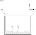
- FIG. 6a is a cross-sectional view illustrating a cooling water tank 300.
- FIG. 6b is a plan view illustrating the cooling water tank 300.
- FIG. 7 is a perspective view illustrating a base plate 400.
- FIG. 1 is a perspective view illustrating a separator cutting apparatus of the present disclosure.
- FIG. 2 is a perspective view illustrating a state in which a sample seating jig 100 and a sample fixing jig 200
- FIG. 8 is a front view illustrating a front of the separator cutting apparatus of the present disclosure.
- FIG. 9 is a block diagram illustrating a separator cutting method of the present disclosure.
- FIG. 10 is SEM images showing cross-sections of separators cut by microtoming and the separator cutting apparatus of the present disclosure.
- a z-axis direction may be a vertical direction
- an x-axis direction may be a first direction
- a y-axis direction may be a second direction.
- the vertical, first, and second directions may be orthogonal to each other.
- the separator cutting apparatus of the present disclosure may be capable of producing a cut surface of a separator for cross-sectional observation in a short time and with uniform quality, regardless of an analyst's skill level.
- the separator cutting apparatus of the present disclosure may be capable of producing a large amount of analysis samples in a short time.
- the separator cutting apparatus of the present disclosure may include:
- the separator cutting apparatus of the present disclosure may cool the separator by immersing it in a refrigerant such as liquid nitrogen, and then cut the separator 11 to be analyzed with a blade to form a cross-section.
- a refrigerant such as liquid nitrogen
- the separator 11 to be analyzed, which is to be cut may be, for example, a thin film of an insulating material and a film that allows only lithium ions to pass through fine holes of 0.01 ⁇ m to 1 ⁇ m, and may be made of polyethylene (PE), polypropylene (PP), and the like.
- PE polyethylene
- PP polypropylene
- the blade insertion groove 111 may be formed in the separator seating surface 113 and prepared in a shape extending in the vertical direction. An upper end of the inner peripheral surface of the blade insertion groove 111 is open, so that the separator cutting blade 700 descending from above the sample seating jig 100 can be seated in the blade insertion groove 111 through the upper end of the blade insertion groove 111.
- the separator cutting blade 700 may be seated in the blade insertion groove 111 so that a part of it is located inside the blade insertion groove 111 and the remaining part protrudes outside an entrance of the blade insertion groove 111.
- a pair of the sample fixing jigs 200 may be provided.
- the pair of sample fixing jigs 200 may be fixed in close contact with the separator seating surface 113 while being spaced apart in the second direction with the blade insertion groove 111 therebetween.
- One side of the separator 11 to be analyzed may be in close contact with the separator seating surface 113, and the other side may be in close contact with the sample fixing jig 200.
- the separator 11 to be analyzed may be sandwiched between the sample seating jig 100 and the sample fixing jig 200 to fix its position.
- the length in the second direction of the sample fixing jig 200 may be less than half the length in the second direction of the sample seating jig 100.
- a surface facing the separator seating surface 113 may be formed as a flat surface.
- the sample fixingjig 200 may be in close contact with the sample seating jig 100 by magnetic force.
- a material of the sample fixing jig 200 may be ferromagnetic.
- the sample fixing jig 200 may be provided in the form of a rod extending in the vertical direction, and an upper end of the sample fixing jig 200 may be bent in the first direction.
- the sample fixing jig 200 may be provided as a square pillar extending in the vertical direction with a plane perpendicular to the first direction as its side surface, and an upper part may be bent in the first direction. The bent upper part of the sample fixing jig 200 may facilitate applying force when separating the sample fixing jig 200 from the sample seating jig 100.
- the sample seating jig 100 may include a seating jig body member 110 having one side formed as the separator seating surface 113 and a plurality of magnet members 120 embedded in the separator seating surface 113.
- the seating jig body member 110 may be provided in a pillar shape having a plane perpendicular to the first direction as the separator seating surface 113.
- An upper end of the seating jig body member 110 may be formed to be split by the blade insertion groove 111.
- a lower end of the seating jig body member 110 may be formed with a larger area than its upper part.
- a bottom surface of the seating jig body member 110 may be formed in a rectangular shape.
- Grooves may be formed in the separator seating surface 113, and the plurality of magnet members 120 may be inserted and embedded into the grooves and coupled to the seating jig body member 110.
- the plurality of magnet members 120 may be arranged to be aligned in the vertical direction.
- the plurality of magnet members 120 may be arranged on both sides of the blade insertion groove 111 to be aligned in the vertical direction.
- the sample seating jig 100 may be provided with a handle member 112 extending upward.
- the handle member 112 may be fixedly coupled to the seating jig body member 110, and an upper end of the handle member 112 may be located higher than the upper end of the seating jig body member 110.
- the cooling water tank 300 may be a water tank with an open top.
- the cooling water tank 300 may be provided in a rectangular parallelepiped shape with an open top.
- a jig alignment groove 310 in which a lower end of the sample seating jig 100 is seated may be formed in a bottom surface of the cooling water tank 300 and the lower end of the sample seating jig 100 may be seated in the jig alignment groove 310 and aligned in place.
- the lower end of the seating jig body member 110 may be seated in the jig alignment groove 310.
- the cooling water tank 300 may be filled with liquid nitrogen so that a part or the whole of the blade insertion groove 111 is immersed, and the seating jig body member 110 and the cooling water tank 300 may be made of the same material.
- the material of the cooling water tank 300 and the seating jig body member 110 may be Teflon material.
- the seating jig body member 110 may be attached to or detached from the cooling water tank 300 regardless of temperature.
- the shape of an entrance of the jig alignment groove 310 may be formed to correspond to the bottom surface of the seating jig body member 110 so that an inner peripheral surface of the jig alignment groove 310 can be brought into close contact with a side of the seating jig body member 110.
- an extension groove 311 may be provided in the bottom surface of the cooling water tank 300.
- the extension groove 311 may be connected to the jig alignment groove 310.
- the sample settling jig 100 may be coupled to or separated from the cooling water tank 300 while the cooling water tank 300 is filled with liquid nitrogen.
- the extension groove 311 may allow inflow or discharge of liquid nitrogen into the jig alignment groove 310 when attaching or detaching the sample seating jig 100 to prevent the attachment and detachment of the sample seating jig 100 from being interrupted due to pressure or volume of the liquid nitrogen.
- a tank alignment groove 421 in which a lower end of the cooling water tank 300 is seated may be formed in the upper surface of the base plate 400.
- the tank alignment groove 421 and pillar insertion grooves 422 in which the lower ends of the support pillars 410 are seated may be formed.
- the sample seating jig 100 may be aligned in place by the jig alignment groove 310, and the cooling water tank 300 may be aligned in place by the tank alignment groove 421, so that the separator 11 to be analyzed may be aligned at a position where it can be cut with respect to the separator cutting blade 700.
- the guide unit 500 may include a guide bar 510 which extends in the first direction and to which the moving unit 600 is coupled so as to be slidable in the first direction, and a pair of guide members 520 fixed to both ends of the guide bar 510 and coupled to the pair of support pillars 410, respectively, so as to be slidable in the vertical direction.
- the guide bar 510 may be provided in the form of a rod extending in the first direction.
- a penetrating hole penetrating the moving unit 600 in the first direction may be formed in the moving unit 600, and the guide bar 510 may be seated in the penetrating hole.
- At least two guide bars 510 may be provided to prevent the moving unit 600 from tilting.
- the guide members 520 may be provided as a pair and fixedly coupled to both ends of the guide bar 510.
- the guide member 520 may be coupled to the support pillar 410 so that it can move linearly in the vertical direction.
- the separator cutting apparatus of the present disclosure may further include a pair of elastic springs 411, lower ends of which are supported on the upper surface of the base plate 400, upper ends of which are supported on the pair of guide members 520, respectively, and which can be contracted or expanded in the vertical direction, and each of the pair of support pillars 410 may be fitted into the center of each of the pair of elastic springs 411.
- a pair of elastic springs 411 lower ends of which are supported on the upper surface of the base plate 400, upper ends of which are supported on the pair of guide members 520, respectively, and which can be contracted or expanded in the vertical direction, and each of the pair of support pillars 410 may be fitted into the center of each of the pair of elastic springs 411.
- the separator cutting apparatus of the present disclosure is capable of cutting the separator 11 to be analyzed in an ultra-low temperature atmosphere created by liquid nitrogen. At this time, the separator cutting blade 700 may be damaged even if it is used to cut the separator 11 to be analyzed only once. Reusing the damaged separator cutting blade 700 may reduce reproducibility of analysis experiments and cause errors in analysis results.
- the separator cutting apparatus of the present disclosure may cut the separator 11 to be analyzed with the separator cutting blade 700 and then move the separator cutting blade 700 in the first direction by a predetermined distance through the moving unit 600 to cut the separator 11 to be analyzed using an unused portion of the separator cutting blade 700.
- the moving unit 600 may include a pair of moving members having planes perpendicular to the second direction, and the pair of moving members may be coupled with a bolt with the separator cutting blade 700 interposed therebetween.
- the separator cutting blade 700 is a consumable item and must be replaced after being used a certain number of times.
- the separator cutting apparatus of the present disclosure may allow the separator cutting blade 700 to be easily replaced by fixing the separator cutting blade 700 to the moving unit 600 in a prefabricated manner rather than an adhesive type, and may easily maintain the same cutting conditions before and after replacement of the separator cutting blade 700.
- a separator cutting method of the present disclosure may include:
- the liquid nitrogen may be injected into the cooling water tank 300 so that the liquid level formed by the liquid nitrogen is located below the upper end of the handle member 112.
- FIG. 10 is SEM images showing a cross-section of a separator produced by microtoming used to manufacture a separator cross-section conventionally, and a cross-section of a separator manufactured with the separator cutting apparatus of the present disclosure.
- the image on the left is the cross-section of the separator produced by microtoming
- the image on the right is the cross-section of the separator manufactured with the separator cutting apparatus of the present disclosure.
- the separator cutting apparatus of the present disclosure may produce a separator cross-section in a short time, and it can be seen that the thickness of the produced separator is almost the same as the thickness of the separator produced by microtoming.
- a separator cutting apparatus of the present disclosure may be capable of performing cutting of a separator for cross-sectional analysis of the separator in a short time and minimizing cross-section damage due to cutting.
- the separator cutting apparatus of the present disclosure may allow anyone to easily produce a cross-section of the separator with a simple operation, enabling rapid observation and analysis of the separator.
Landscapes
- Engineering & Computer Science (AREA)
- Life Sciences & Earth Sciences (AREA)
- Forests & Forestry (AREA)
- Mechanical Engineering (AREA)
- Manufacturing & Machinery (AREA)
- Chemical & Material Sciences (AREA)
- Chemical Kinetics & Catalysis (AREA)
- Electrochemistry (AREA)
- General Chemical & Material Sciences (AREA)
- Physics & Mathematics (AREA)
- Optics & Photonics (AREA)
- Sampling And Sample Adjustment (AREA)
Abstract
Description
- The present application claims the benefit of priority based on
Korean Patent Application No. 10-2023-0043618 filed on April 3, 2023 - The present disclosure relates to a separator cutting apparatus for performing cutting of a separator for cross-sectional analysis of the separator in a short time and minimizing cross-section damage caused by cutting.
- A separator used in an electrochemical device such as a secondary battery transmits ions while blocking flow of electrons between an anode and a cathode.
- In other words, the separator is a thin film of insulating material, which plays a role in allowing only lithium ions to pass through micropores of 0.01 µm to 1 µm. The separator may be mainly manufactured from polyethylene (PE) and polypropylene (PP).
- The separator may prevent short circuits by preventing direct contact between the anode and cathode, and allow lithium ions to move through micropores provided inside. At this time, when the lithium ions pass through the separator and move from the anode to the cathode, the secondary battery can be charged, and when they move from the cathode to the anode, the secondary battery can be discharged. In addition, when the temperature of a cell rises above a predetermined level, the micropores are blocked and the separator may prevent short circuits inside the secondary battery. The separator may be equipped with high mechanical strength and play a role in ensuring safety by blocking by-products or foreign substances generated inside.
- As described above, in designing a separator to enable the separator to function, it may be important to observe the cross-section of the separator to understand its structure.
- Specifically, the separator may be deformed by conditions such as pressure and temperature applied during a manufacturing process, use environment, etc. and in order to observe the degree of deformation at this time, it is required to cut the separator to form a cross-section to be observed.
- However, production of the cross-section of the separator has been performed only with equipment requiring proficiency, such as low-temperature microtoming or ion milling.
- For rapid observation and analysis, a technology is required that allows anyone to easily produce a cross-section of a separator with a simple operation.
- The present disclosure relates to a separator cutting apparatus and an object of the present disclosure is to provide a separator cutting apparatus for performing cutting of a separator for cross-sectional analysis of the separator in a short time and minimizing cross-section damage caused by cutting.
- Technical objects to be achieved by the present disclosure are not limited to the technical objects mentioned above, and other technical objects not mentioned will be clearly understood by those skilled in the art from the description below.
- A separator cutting apparatus of the present disclosure may include:
- a sample seating jig having a separator seating surface parallel to a vertical direction;
- a sample fixing jig which is closely fixed to the separator seating surface with a separator to be analyzed interposed therebetween;
- a cooling water tank accommodating the sample seating jig inside;
- a base plate having an upper surface on which the cooling water tank is mounted;
- a pair of support pillars which have lower ends fixed to the upper surface of the base plate and are spaced apart from each other in a first direction perpendicular to the vertical direction;
- a guide unit which is extended in the first direction and has both ends each of which is coupled to each of the pair of support pillars so as to be slidable in the vertical direction;
- a moving unit coupled to the guide unit so as to be slidable in the first direction; and
- a separator cutting blade mounted on a lower end of the moving unit,
- wherein a blade insertion groove for inserting the separator cutting blade may be formed in the sample seating jig, and
- the blade insertion groove may be formed in a shape traversing the separator seating surface in the vertical direction.
- A separator cutting apparatus of the present disclosure may be capable of performing cutting of a separator for cross-sectional analysis of the separator in a short time and minimizing cross-section damage due to cutting.
- The separator cutting apparatus of the present disclosure may allow anyone to easily produce a cross-section of the separator with a simple operation, enabling rapid observation and analysis of the separator.
-
-
FIG. 1 is a perspective view illustrating a separator cutting apparatus of the present disclosure. -
FIG. 2 is a perspective view illustrating a state in which a sample seating jig and a sample fixing jig are coupled. -
FIG. 3 is a cross-sectional view illustrating an A-A' cross-section ofFIG. 2 . -
FIG. 4 is a plan view illustrating a side of the sample fixing jig. -
FIG. 5 is a perspective view illustrating the sample seating jig. -
FIG. 6a is a cross-sectional view illustrating a cooling water tank. -
FIG. 6b is a plan view illustrating the cooling water tank. -
FIG. 7 is a perspective view illustrating a base plate. -
FIG. 8 is a front view illustrating a front of a separator cutting apparatus of the present disclosure. -
FIG. 9 is a block diagram illustrating a separator cutting method of the present disclosure. -
FIG. 10 is SEM images showing cross-sections of separators cut by microtoming and a separator cutting apparatus of the present disclosure. - A separator cutting apparatus of the present disclosure may include:
- a sample seating jig having a separator seating surface parallel to a vertical direction;
- a sample fixing jig which is closely fixed to the separator seating surface with a separator to be analyzed interposed therebetween;
- a cooling water tank accommodating the sample seating jig inside;
- a base plate having an upper surface on which the cooling water tank is mounted;
- a pair of support pillars which have lower ends fixed to the upper surface of the base plate and are spaced apart from each other in a first direction perpendicular to the vertical direction;
- a guide unit which is extended in the first direction and has both ends each of which is coupled to each of the pair of support pillars so as to be slidable in the vertical direction;
- a moving unit coupled to the guide unit so as to be slidable in the first direction; and
- a separator cutting blade mounted on a lower end of the moving unit,
- wherein a blade insertion groove for inserting the separator cutting blade may be formed in the sample seating jig, and
- the blade insertion groove may be formed in a shape traversing the separator seating surface in the vertical direction.
- In the separator cutting apparatus of the present disclosure, when the first direction is a direction perpendicular to the separator seating surface, and a second direction is a direction perpendicular to the first direction and the vertical direction, a pair of the sample fixing jigs may be provided, and the pair of sample fixing jigs may be fixed in close contact with the separator seating surface while being spaced apart in the second direction with the blade insertion groove therebetween.
- In the separator cutting apparatus of the present disclosure, the sample fixing jig may be in close contact with the sample seating jig by magnetic force.
- In the separator cutting apparatus of the present disclosure, the first direction may be a direction perpendicular to the separator seating surface, the sample fixing jig may be provided in the form of a rod extending in the vertical direction, and an upper end of the sample fixing jig may be bent in the first direction.
- In the separator cutting apparatus of the present disclosure, a jig alignment groove in which a lower end of the sample seating jig is seated may be formed in a bottom surface of the cooling water tank, and the lower end of the sample seating jig may be seated in the jig alignment groove and aligned in place.
- In the separator cutting apparatus of the present disclosure, the sample seating jig may include a seating jig body member having one side formed as the separator seating surface and a plurality of magnet members embedded in the separator seating surface, and a lower end of the seating jig body member may be seated in the jig alignment groove.
- In the separator cutting apparatus of the present disclosure, the cooling water tank may be filled with liquid nitrogen so that a part or the whole of the blade insertion groove is immersed, and the seating jig body member and the cooling water tank may be formed of the same material.
- In the separator cutting apparatus of the present disclosure, a tank alignment groove in which a lower end of the cooling water tank is seated may be formed in the upper surface of the base plate.
- In the separator cutting apparatus of the present disclosure, the guide unit may include a guide bar which extends in the first direction and to which the moving unit is coupled so as to be slidable in the first direction, and a pair of guide members fixed to both ends of the guide bar and coupled to the pair of support pillars, respectively, so as to be slidable in the vertical direction.
- The separator cutting apparatus of the present disclosure may further include a pair of elastic springs, lower ends of which are supported on the upper surface of the base plate, upper ends of which are supported on the pair of guide members, respectively, and which is capable of being contracted or expanded in the vertical direction, and each of the pair of support pillars may be fitted into the center of each of the pair of elastic springs.
- A separator cutting method using the separator cutting apparatus of the present disclosure may include:
- a separator seating step of seating the separator to be analyzed on the separator seating surface to cover the blade insertion groove;
- a separator fixing step of attaching the sample fixing jig to the separator seating surface with the separator to be analyzed in between;
- a separator alignment step of inserting the lower end of the sample seating jig into the jig alignment groove to position the sample seating jig inside the cooling water tank;
- an ethanol application step of applying ethanol to the separator to be analyzed;
- a liquid nitrogen injection step of injecting liquid nitrogen into the cooling water tank;
- a separator cutting step of lowering the moving unit and inserting the separator cutting blade into the blade insertion groove to cut the separator to be analyzed;
- a jig ejection step of removing the sample seating jig from the cooling water tank; and
- a separator separation step of separating the separator to be analyzed from the sample seating jig.
- In the separator cutting method of the present disclosure, the sample seating jig may be provided with a handle member extending upward, and in the liquid nitrogen injection step, the liquid nitrogen may be injected into the cooling water tank so that a liquid level formed by the liquid nitrogen is located below an upper end of the handle member.
- Hereinafter, embodiments according to the present disclosure will be described in detail with reference to the accompanying drawings. In this process, the size or shape of the components shown in the drawings may be exaggerated for clarity and convenience of explanation. In addition, terms specifically defined in consideration of the configuration and operation of the present disclosure may vary according to the intentions or customs of users and operators. Definitions of these terms should be made based on the content throughout this specification.
- In the description of the present disclosure, it should be noted that an orientation or positional relationship indicated by the terms such as "center", "upper", "lower", "left", "right", "vertical", "horizontal", "inner side", "outer side", "one side", and "other side" is based on an orientation or positional relationship shown in a drawing or an orientation or positional relationship that is placed when using the product of the present disclosure on a daily basis, and is merely for explanation and brief description of the present disclosure, and it does not suggest or imply that the shown device or element must necessarily be configured or operated in a specified orientation and should not be construed as limiting the present disclosure.
-
FIG. 1 is a perspective view illustrating a separator cutting apparatus of the present disclosure.FIG. 2 is a perspective view illustrating a state in which asample seating jig 100 and asample fixing jig 200 are coupled.FIG. 3 is a cross-sectional view illustrating an A-A' cross-section ofFIG. 2 .FIG. 4 is a plan view illustrating a side of thesample fixing jig 200.FIG. 5 is a perspective view illustrating thesample seating jig 100.FIG. 6a is a cross-sectional view illustrating a coolingwater tank 300.FIG. 6b is a plan view illustrating the coolingwater tank 300.FIG. 7 is a perspective view illustrating abase plate 400.FIG. 8 is a front view illustrating a front of the separator cutting apparatus of the present disclosure.FIG. 9 is a block diagram illustrating a separator cutting method of the present disclosure.FIG. 10 is SEM images showing cross-sections of separators cut by microtoming and the separator cutting apparatus of the present disclosure. - Hereinafter, referring to
FIGS. 1 to 10 , the separator cutting apparatus of the present disclosure will be described in detail. InFIGS. 1 to 8 , a z-axis direction may be a vertical direction, an x-axis direction may be a first direction, and a y-axis direction may be a second direction. The vertical, first, and second directions may be orthogonal to each other. - The separator cutting apparatus of the present disclosure may be capable of producing a cut surface of a separator for cross-sectional observation in a short time and with uniform quality, regardless of an analyst's skill level.
- The separator cutting apparatus of the present disclosure may be capable of producing a large amount of analysis samples in a short time.
- As shown in
FIGS. 1 and2 , the separator cutting apparatus of the present disclosure may include: - the
sample seating jig 100 having aseparator seating surface 113 parallel to the vertical direction; - the
sample fixing jig 200 which is closely fixed to the separator seating surface with aseparator 11 to be analyzed interposed therebetween; - the cooling
water tank 300 accommodating thesample seating jig 100 inside; - the
base plate 400 having an upper surface on which thecooling water tank 300 is mounted; - a pair of
support pillars 410 which have lower ends fixed to the upper surface of thebase plate 400 and are spaced apart from each other in the first direction perpendicular to the vertical direction; - a
guide unit 500 which is extended in the first direction and has both ends each of which is coupled to each of the pair ofsupport pillars 410 so as to be slidable in the vertical direction; - a moving
unit 600 coupled to theguide unit 500 so as to be slidable in the first direction; and - a
separator cutting blade 700 mounted on a lower end of the movingunit 600, - wherein a
blade insertion groove 111 for inserting theseparator cutting blade 700 may be formed in thesample seating jig 100, and - the
blade insertion groove 111 may be formed in a shape traversing theseparator seating surface 113 in the vertical direction. - The separator cutting apparatus of the present disclosure may cool the separator by immersing it in a refrigerant such as liquid nitrogen, and then cut the
separator 11 to be analyzed with a blade to form a cross-section. - For the separator cutting apparatus of the present disclosure, the
separator 11 to be analyzed, which is to be cut, may be, for example, a thin film of an insulating material and a film that allows only lithium ions to pass through fine holes of 0.01 µm to 1 µm, and may be made of polyethylene (PE), polypropylene (PP), and the like. - One side of the
sample seating jig 100 may be formed as theseparator seating surface 113, and theseparator seating surface 113 may be formed as a plane perpendicular to the first direction. Theblade insertion groove 111 may be formed in theseparator seating surface 113 and prepared in a shape extending in the vertical direction. An upper end of the inner peripheral surface of theblade insertion groove 111 is open, so that theseparator cutting blade 700 descending from above thesample seating jig 100 can be seated in theblade insertion groove 111 through the upper end of theblade insertion groove 111. Theseparator cutting blade 700 may be seated in theblade insertion groove 111 so that a part of it is located inside theblade insertion groove 111 and the remaining part protrudes outside an entrance of theblade insertion groove 111. - As shown in
FIGS. 2 and3 , a pair of thesample fixing jigs 200 may be provided. The pair ofsample fixing jigs 200 may be fixed in close contact with theseparator seating surface 113 while being spaced apart in the second direction with theblade insertion groove 111 therebetween. One side of theseparator 11 to be analyzed may be in close contact with theseparator seating surface 113, and the other side may be in close contact with thesample fixing jig 200. In other words, theseparator 11 to be analyzed may be sandwiched between thesample seating jig 100 and thesample fixing jig 200 to fix its position. - The length in the second direction of the
sample fixing jig 200 may be less than half the length in the second direction of thesample seating jig 100. - Among surfaces of the
sample fixing jig 200, a surface facing theseparator seating surface 113 may be formed as a flat surface. The sample fixingjig 200 may be in close contact with thesample seating jig 100 by magnetic force. A material of thesample fixing jig 200 may be ferromagnetic. - As shown in
FIG. 4 , thesample fixing jig 200 may be provided in the form of a rod extending in the vertical direction, and an upper end of thesample fixing jig 200 may be bent in the first direction. For example, thesample fixing jig 200 may be provided as a square pillar extending in the vertical direction with a plane perpendicular to the first direction as its side surface, and an upper part may be bent in the first direction. The bent upper part of thesample fixing jig 200 may facilitate applying force when separating thesample fixing jig 200 from thesample seating jig 100. - As shown in
FIG. 5 , thesample seating jig 100 may include a seatingjig body member 110 having one side formed as theseparator seating surface 113 and a plurality ofmagnet members 120 embedded in theseparator seating surface 113. - For example, the seating
jig body member 110 may be provided in a pillar shape having a plane perpendicular to the first direction as theseparator seating surface 113. An upper end of the seatingjig body member 110 may be formed to be split by theblade insertion groove 111. A lower end of the seatingjig body member 110 may be formed with a larger area than its upper part. A bottom surface of the seatingjig body member 110 may be formed in a rectangular shape. - Grooves may be formed in the
separator seating surface 113, and the plurality ofmagnet members 120 may be inserted and embedded into the grooves and coupled to the seatingjig body member 110. For example, fourmagnet members 120 may be provided and placed two by two with theblade insertion groove 111 in between. The plurality ofmagnet members 120 may be arranged to be aligned in the vertical direction. Specifically, the plurality ofmagnet members 120 may be arranged on both sides of theblade insertion groove 111 to be aligned in the vertical direction. - The
sample seating jig 100 may be provided with ahandle member 112 extending upward. Thehandle member 112 may be fixedly coupled to the seatingjig body member 110, and an upper end of thehandle member 112 may be located higher than the upper end of the seatingjig body member 110. - As shown in
FIG. 6a , the coolingwater tank 300 may be a water tank with an open top. For example, the coolingwater tank 300 may be provided in a rectangular parallelepiped shape with an open top. Ajig alignment groove 310 in which a lower end of thesample seating jig 100 is seated may be formed in a bottom surface of the coolingwater tank 300 and the lower end of thesample seating jig 100 may be seated in thejig alignment groove 310 and aligned in place. Specifically, the lower end of the seatingjig body member 110 may be seated in thejig alignment groove 310. - The cooling
water tank 300 may be filled with liquid nitrogen so that a part or the whole of theblade insertion groove 111 is immersed, and the seatingjig body member 110 and the coolingwater tank 300 may be made of the same material. For example, the material of the coolingwater tank 300 and the seatingjig body member 110 may be Teflon material. Specifically, by setting thermal expansion rates of the seatingjig body member 110 and the coolingwater tank 300 to the same level, the seatingjig body member 110 may be attached to or detached from the coolingwater tank 300 regardless of temperature. - The shape of an entrance of the
jig alignment groove 310 may be formed to correspond to the bottom surface of the seatingjig body member 110 so that an inner peripheral surface of thejig alignment groove 310 can be brought into close contact with a side of the seatingjig body member 110. - As shown in
FIG. 6b , anextension groove 311 may be provided in the bottom surface of the coolingwater tank 300. Theextension groove 311 may be connected to thejig alignment groove 310. In the separator cutting apparatus of the present disclosure, thesample settling jig 100 may be coupled to or separated from the coolingwater tank 300 while the coolingwater tank 300 is filled with liquid nitrogen. Theextension groove 311 may allow inflow or discharge of liquid nitrogen into thejig alignment groove 310 when attaching or detaching thesample seating jig 100 to prevent the attachment and detachment of thesample seating jig 100 from being interrupted due to pressure or volume of the liquid nitrogen. - As shown in
FIG. 7 , atank alignment groove 421 in which a lower end of the coolingwater tank 300 is seated may be formed in the upper surface of thebase plate 400. In thebase plate 400, thetank alignment groove 421 andpillar insertion grooves 422 in which the lower ends of thesupport pillars 410 are seated may be formed. For the separator cutting apparatus of the present disclosure, thesample seating jig 100 may be aligned in place by thejig alignment groove 310, and the coolingwater tank 300 may be aligned in place by thetank alignment groove 421, so that theseparator 11 to be analyzed may be aligned at a position where it can be cut with respect to theseparator cutting blade 700. - As shown in
FIG. 8 , theguide unit 500 may include aguide bar 510 which extends in the first direction and to which the movingunit 600 is coupled so as to be slidable in the first direction, and a pair ofguide members 520 fixed to both ends of theguide bar 510 and coupled to the pair ofsupport pillars 410, respectively, so as to be slidable in the vertical direction. - The
guide bar 510 may be provided in the form of a rod extending in the first direction. A penetrating hole penetrating the movingunit 600 in the first direction may be formed in the movingunit 600, and theguide bar 510 may be seated in the penetrating hole. At least twoguide bars 510 may be provided to prevent the movingunit 600 from tilting. - The
guide members 520 may be provided as a pair and fixedly coupled to both ends of theguide bar 510. Theguide member 520 may be coupled to thesupport pillar 410 so that it can move linearly in the vertical direction. - The separator cutting apparatus of the present disclosure may further include a pair of
elastic springs 411, lower ends of which are supported on the upper surface of thebase plate 400, upper ends of which are supported on the pair ofguide members 520, respectively, and which can be contracted or expanded in the vertical direction, and each of the pair ofsupport pillars 410 may be fitted into the center of each of the pair ofelastic springs 411. When an analyst pressurizes the movingunit 600 downward and cuts theseparator 11 to be analyzed with theseparator cutting blade 700, and the pressure exerted by the analyst on the movingunit 600 is relieved, the movingunit 600 may return to its original position by recovery force of theelastic spring 411. - The
separator cutting blade 700 may be a blade that extends in the first direction. The blade of theseparator cutting blade 700 may be formed to face downward, and an upper end of theseparator cutting blade 700 may be fixed and coupled to the lower end of the movingunit 600. - The separator cutting apparatus of the present disclosure is capable of cutting the
separator 11 to be analyzed in an ultra-low temperature atmosphere created by liquid nitrogen. At this time, theseparator cutting blade 700 may be damaged even if it is used to cut theseparator 11 to be analyzed only once. Reusing the damagedseparator cutting blade 700 may reduce reproducibility of analysis experiments and cause errors in analysis results. The separator cutting apparatus of the present disclosure may cut theseparator 11 to be analyzed with theseparator cutting blade 700 and then move theseparator cutting blade 700 in the first direction by a predetermined distance through the movingunit 600 to cut theseparator 11 to be analyzed using an unused portion of theseparator cutting blade 700. - In addition, the moving
unit 600 may include a pair of moving members having planes perpendicular to the second direction, and the pair of moving members may be coupled with a bolt with theseparator cutting blade 700 interposed therebetween. For the separator cutting apparatus of the present disclosure, theseparator cutting blade 700 is a consumable item and must be replaced after being used a certain number of times. As described above, the separator cutting apparatus of the present disclosure may allow theseparator cutting blade 700 to be easily replaced by fixing theseparator cutting blade 700 to the movingunit 600 in a prefabricated manner rather than an adhesive type, and may easily maintain the same cutting conditions before and after replacement of theseparator cutting blade 700. - As shown in
FIG. 9 , a separator cutting method of the present disclosure may include: - a separator seating step S10 of seating the
separator 11 to be analyzed on theseparator seating surface 113 to cover theblade insertion groove 111; - a separator fixing step S20 of attaching the
sample fixing jig 200 to theseparator seating surface 113 with theseparator 11 to be analyzed in between; - a separator alignment step S30 of inserting the lower end of the
sample seating jig 100 into thejig alignment groove 310 to position thesample seating jig 100 inside the coolingwater tank 300; - an ethanol application step S40 of applying ethanol to the
separator 11 to be analyzed; - a liquid nitrogen injection step S50 of injecting liquid nitrogen into the cooling
water tank 300; - a separator cutting step S60 of lowering the moving
unit 600 and inserting theseparator cutting blade 700 into theblade insertion groove 111 to cut theseparator 11 to be analyzed; - a jig ejection step S70 of removing the
sample seating jig 100 from the coolingwater tank 300; and - a separator separation step S80 of separating the
separator 11 to be analyzed from thesample seating jig 100. - In the liquid nitrogen injection step, the liquid nitrogen may be injected into the cooling
water tank 300 so that the liquid level formed by the liquid nitrogen is located below the upper end of thehandle member 112. -
FIG. 10 is SEM images showing a cross-section of a separator produced by microtoming used to manufacture a separator cross-section conventionally, and a cross-section of a separator manufactured with the separator cutting apparatus of the present disclosure. InFIG. 10 , the image on the left is the cross-section of the separator produced by microtoming, and the image on the right is the cross-section of the separator manufactured with the separator cutting apparatus of the present disclosure. The separator cutting apparatus of the present disclosure may produce a separator cross-section in a short time, and it can be seen that the thickness of the produced separator is almost the same as the thickness of the separator produced by microtoming. - Although embodiments according to the present disclosure have been described above, they are merely illustrative and those skilled in the art will understand that various modifications and embodiments of equivalent range are possible therefrom. Therefore, the true technical protection scope of the present disclosure should be defined by the appended claims.
- [Explanation of Symbols] 11... Separator to be analyzed, 100... Sample seating jig, 110...Seating jig body member, 111...Blade insertion groove, 112... Handle member, 113... Separator seating surface, 120...Magnet member, 200... Sample fixing jig, 300...Cooling water tank, 310...Jig alignment groove, 311... Extension groove, 400...Base plate, 410... Support pillar, 411...Elastic spring, 421...Tank alignment groove, 422...Pillar insertion groove, 500...Guide unit, 510...Guide bar, 520...Guide member, 600... Moving unit, 700...Separator cutting blade
- A separator cutting apparatus of the present disclosure may be capable of performing cutting of a separator for cross-sectional analysis of the separator in a short time and minimizing cross-section damage due to cutting.
- The separator cutting apparatus of the present disclosure may allow anyone to easily produce a cross-section of the separator with a simple operation, enabling rapid observation and analysis of the separator.
Claims (12)
- A separator cutting apparatus comprising:a sample seating jig having a separator seating surface parallel to a vertical direction;a sample fixing jig which is closely fixed to the separator seating surface with a separator to be analyzed interposed therebetween;a cooling water tank accommodating the sample seating jig inside;a base plate having an upper surface on which the cooling water tank is mounted;a pair of support pillars each having a lower end fixed to the upper surface of the base plate, wherein the pair of support pillars are spaced apart from each other in a first direction perpendicular to the vertical direction;a guide unit extending in the first direction and comprising both ends each of which is coupled to each of the pair of support pillars so the guide unit is slidable in the vertical direction;a moving unit coupled to the guide unit so as to be slidable in the first direction; anda separator cutting blade mounted on a lower end of the moving unit,wherein a blade insertion groove for inserting the separator cutting blade is formed in the sample seating jig, andthe blade insertion groove is formed in a shape traversing the separator seating surface in the vertical direction.
- The separator cutting apparatus of claim 1, wherein the first direction is a direction perpendicular to the separator seating surface, anda second direction is a direction perpendicular to the first direction and the vertical direction, andwherein a pair of the sample fixing jigs are provided, andthe pair of sample fixing jigs are fixed in close contact with the separator seating surface while being spaced apart in the second direction with the blade insertion groove therebetween.
- The separator cutting apparatus of claim 1, wherein the sample fixing jig is in close contact with the sample seating jig by magnetic force.
- The separator cutting apparatus of claim 2, wherein the sample fixing jig is provided in the form of a rod extending in the vertical direction, and
an upper end of the sample fixing jig is bent in the first direction. - The separator cutting apparatus of claim 1, wherein a bottom surface of the cooling water tank comprises a jig alignment groove in which a lower end of the sample seating jig is seated, and
the lower end of the sample seating jig is seated in the jig alignment groove and aligned in place. - The separator cutting apparatus of claim 5, wherein the sample seating jig comprises:a seating jig body member having one side formed as the separator seating surface; anda plurality of magnet members embedded in the separator seating surface, anda lower end of the seating jig body member is seated in the jig alignment groove.
- The separator cutting apparatus of claim 6, wherein the cooling water tank is filled with liquid nitrogen so that a part or the whole of the blade insertion groove is immersed, and
the seating jig body member and the cooling water tank are formed of the same material. - The separator cutting apparatus of claim 5, wherein a tank alignment groove in which a lower end of the cooling water tank is seated is formed in the upper surface of the base plate.
- The separator cutting apparatus of claim 1, wherein the guide unit comprises:a guide bar which extends in the first direction and to which the moving unit is coupled so as to be slidable in the first direction; anda pair of guide members fixed to both ends of the guide bar and coupled to the pair of support pillars, respectively, so as to be slidable in the vertical direction.
- The separator cutting apparatus of claim 9 further comprising:a pair of elastic springs, lower ends of which are supported on the upper surface of the base plate, upper ends of which are supported on the pair of guide members, respectively, and which is capable of being contracted or expanded in the vertical direction,wherein each of the pair of support pillars is fitted into the center of each of the pair of elastic springs.
- A separator cutting method using the separator cutting apparatus of claim 5, comprising:a separator seating step of seating the separator to be analyzed on the separator seating surface to cover the blade insertion groove;a separator fixing step of attaching the sample fixing jig to the separator seating surface with the separator to be analyzed in between;a separator alignment step of inserting the lower end of the sample seating jig into the jig alignment groove to position the sample seating jig inside the cooling water tank;an ethanol application step of applying ethanol to the separator to be analyzed;a liquid nitrogen injection step of injecting liquid nitrogen into the cooling water tank;a separator cutting step of lowering the moving unit and inserting the separator cutting blade into the blade insertion groove to cut the separator to be analyzed;a jig ejection step of removing the sample seating jig from the cooling water tank; anda separator separation step of separating the separator to be analyzed from the sample seating jig.
- The separator cutting method of claim 11, wherein the sample seating jig comprises a handle member extending upward, andin the liquid nitrogen injection step,the liquid nitrogen is injected into the cooling water tank so that a liquid level formed by the liquid nitrogen is located below an upper end of the handle member.
Applications Claiming Priority (2)
| Application Number | Priority Date | Filing Date | Title |
|---|---|---|---|
| KR1020230043618A KR20240148166A (en) | 2023-04-03 | 2023-04-03 | Apparatus for cutting separator |
| PCT/KR2024/095632 WO2024210712A1 (en) | 2023-04-03 | 2024-03-25 | Membrane cutting device |
Publications (2)
| Publication Number | Publication Date |
|---|---|
| EP4535503A1 true EP4535503A1 (en) | 2025-04-09 |
| EP4535503A4 EP4535503A4 (en) | 2025-11-26 |
Family
ID=92973173
Family Applications (1)
| Application Number | Title | Priority Date | Filing Date |
|---|---|---|---|
| EP24785401.1A Pending EP4535503A4 (en) | 2023-04-03 | 2024-03-25 | MEMBRAN CUTTING DEVICE |
Country Status (6)
| Country | Link |
|---|---|
| US (1) | US20260054404A1 (en) |
| EP (1) | EP4535503A4 (en) |
| JP (1) | JP2025522217A (en) |
| KR (1) | KR20240148166A (en) |
| CN (1) | CN119585915A (en) |
| WO (1) | WO2024210712A1 (en) |
Family Cites Families (11)
| Publication number | Priority date | Publication date | Assignee | Title |
|---|---|---|---|---|
| JPH11337461A (en) * | 1998-05-29 | 1999-12-10 | Sony Corp | Preparation jig and preparation method for observation sample |
| US8122804B2 (en) * | 2006-11-01 | 2012-02-28 | Kurume University | Slicing guide device for preparing texture slices, texture slices preparing device, and method for preparing texture slices |
| JP2010085173A (en) * | 2008-09-30 | 2010-04-15 | Toyota Motor Corp | Method for breaking porous member |
| JP2013061164A (en) * | 2011-09-12 | 2013-04-04 | Toppan Printing Co Ltd | Sample preparation device, sample preparation method and sample observation method |
| JP6029824B2 (en) * | 2011-12-06 | 2016-11-24 | 住友化学株式会社 | Sheet material cutting method |
| JP6020147B2 (en) * | 2012-12-26 | 2016-11-02 | 日産自動車株式会社 | Cutting apparatus and cutting method |
| KR101813249B1 (en) * | 2017-02-10 | 2017-12-29 | 신현집 | Apparatus for cutting jelly roll tab of lithium secondary battery |
| CN210981827U (en) * | 2019-10-29 | 2020-07-10 | 柳州钢铁股份有限公司 | Metallographic wire sample sampling device |
| KR20230000625A (en) * | 2021-06-25 | 2023-01-03 | 주식회사 엘지에너지솔루션 | Apparatus for collecting gas |
| KR20230018564A (en) * | 2021-07-30 | 2023-02-07 | 주식회사 엘지에너지솔루션 | Apparatus for cutting battery |
| CN115107108A (en) * | 2022-08-29 | 2022-09-27 | 苏州鼎佳精密科技股份有限公司 | Continuous blanking and waste recovery system of new energy battery insulating sheet |
-
2023
- 2023-04-03 KR KR1020230043618A patent/KR20240148166A/en active Pending
-
2024
- 2024-03-25 JP JP2025500968A patent/JP2025522217A/en active Pending
- 2024-03-25 CN CN202480003398.6A patent/CN119585915A/en active Pending
- 2024-03-25 US US19/099,549 patent/US20260054404A1/en active Pending
- 2024-03-25 WO PCT/KR2024/095632 patent/WO2024210712A1/en not_active Ceased
- 2024-03-25 EP EP24785401.1A patent/EP4535503A4/en active Pending
Also Published As
| Publication number | Publication date |
|---|---|
| KR20240148166A (en) | 2024-10-11 |
| WO2024210712A1 (en) | 2024-10-10 |
| JP2025522217A (en) | 2025-07-11 |
| CN119585915A (en) | 2025-03-07 |
| EP4535503A4 (en) | 2025-11-26 |
| US20260054404A1 (en) | 2026-02-26 |
Similar Documents
| Publication | Publication Date | Title |
|---|---|---|
| KR101813249B1 (en) | Apparatus for cutting jelly roll tab of lithium secondary battery | |
| KR101359983B1 (en) | Tray | |
| DE102012211587B4 (en) | Mass spectrometers with precisely aligned ion optics assemblies | |
| CN109877742B (en) | Method for manufacturing battery pack | |
| WO2017023666A1 (en) | Sectionable cassette and embedding frame with tissue immobilizing separable lid, and methods for preparing biopsy tissue samples | |
| KR102160703B1 (en) | Apparatus for collecting inner gas in secondary electric cell and method thereof | |
| US20140283360A1 (en) | Battery holder and manufacturing method of battery holder | |
| EP3809512A1 (en) | Secondary-battery internal gas collecting apparatus | |
| EP4535503A1 (en) | Membrane cutting device | |
| JP7809182B2 (en) | Universal Modular Test Fixture | |
| JP2002134176A (en) | Charge / discharge / inspection mechanism for lithium polymer batteries | |
| CN113767492A (en) | Apparatus and method for making battery stacks | |
| EP4354571A1 (en) | Battery module manufacturing clamping assembly and method of clamping a battery pallet for welding | |
| CN108941905B (en) | High-efficient accurate tool is used in laser welding | |
| JP2008091233A (en) | Pack battery and manufacturing method thereof | |
| KR102041894B1 (en) | Sample plating apparatus | |
| CN112285141B (en) | Preparation method of irradiated reactor structural material SEM sample and sample box | |
| KR101792817B1 (en) | Battery Pack Manufacturing Device for Mounting Parts for Battery Pack on Top of Battery Cell | |
| KR102798074B1 (en) | System and method for extracting electrolyte | |
| EP4183539B1 (en) | Apparatus and method for cutting electrode, and electrode manufacturing equipment including same | |
| CN217522079U (en) | Battery module aluminium bar welding frock | |
| KR20230018564A (en) | Apparatus for cutting battery | |
| CN112469993B (en) | Stage device for XRD testing of batteries | |
| CN221508105U (en) | FIB comparison analysis stage | |
| KR20180047084A (en) | Method of Manufacturing Battery Cell by Marking Reference Point |
Legal Events
| Date | Code | Title | Description |
|---|---|---|---|
| STAA | Information on the status of an ep patent application or granted ep patent |
Free format text: STATUS: THE INTERNATIONAL PUBLICATION HAS BEEN MADE |
|
| PUAI | Public reference made under article 153(3) epc to a published international application that has entered the european phase |
Free format text: ORIGINAL CODE: 0009012 |
|
| STAA | Information on the status of an ep patent application or granted ep patent |
Free format text: STATUS: REQUEST FOR EXAMINATION WAS MADE |
|
| 17P | Request for examination filed |
Effective date: 20250106 |
|
| AK | Designated contracting states |
Kind code of ref document: A1 Designated state(s): AL AT BE BG CH CY CZ DE DK EE ES FI FR GB GR HR HU IE IS IT LI LT LU LV MC ME MK MT NL NO PL PT RO RS SE SI SK SM TR |
|
| A4 | Supplementary search report drawn up and despatched |
Effective date: 20251027 |
|
| RIC1 | Information provided on ipc code assigned before grant |
Ipc: H01M 10/42 20060101AFI20251021BHEP Ipc: B26D 1/08 20060101ALI20251021BHEP Ipc: H01M 50/403 20210101ALI20251021BHEP |
|
| GRAP | Despatch of communication of intention to grant a patent |
Free format text: ORIGINAL CODE: EPIDOSNIGR1 |
|
| STAA | Information on the status of an ep patent application or granted ep patent |
Free format text: STATUS: GRANT OF PATENT IS INTENDED |
|
| DAV | Request for validation of the european patent (deleted) | ||
| DAX | Request for extension of the european patent (deleted) | ||
| INTG | Intention to grant announced |
Effective date: 20260129 |
|
| GRAS | Grant fee paid |
Free format text: ORIGINAL CODE: EPIDOSNIGR3 |
|
| GRAA | (expected) grant |
Free format text: ORIGINAL CODE: 0009210 |
|
| STAA | Information on the status of an ep patent application or granted ep patent |
Free format text: STATUS: THE PATENT HAS BEEN GRANTED |