EP4535489A1 - Gemischter festkörperionenleiter, festkörperelektrolyt, kathode und elektrochemische vorrichtung damit sowie verfahren zur herstellung des gemischten festkörperionenleiters - Google Patents
Gemischter festkörperionenleiter, festkörperelektrolyt, kathode und elektrochemische vorrichtung damit sowie verfahren zur herstellung des gemischten festkörperionenleiters Download PDFInfo
- Publication number
- EP4535489A1 EP4535489A1 EP24197931.9A EP24197931A EP4535489A1 EP 4535489 A1 EP4535489 A1 EP 4535489A1 EP 24197931 A EP24197931 A EP 24197931A EP 4535489 A1 EP4535489 A1 EP 4535489A1
- Authority
- EP
- European Patent Office
- Prior art keywords
- solid
- state
- formula
- ionic conductor
- mixed
- Prior art date
- Legal status (The legal status is an assumption and is not a legal conclusion. Google has not performed a legal analysis and makes no representation as to the accuracy of the status listed.)
- Pending
Links
Images




Classifications
-
- H—ELECTRICITY
- H01—ELECTRIC ELEMENTS
- H01M—PROCESSES OR MEANS, e.g. BATTERIES, FOR THE DIRECT CONVERSION OF CHEMICAL ENERGY INTO ELECTRICAL ENERGY
- H01M10/00—Secondary cells; Manufacture thereof
- H01M10/05—Accumulators with non-aqueous electrolyte
- H01M10/056—Accumulators with non-aqueous electrolyte characterised by the materials used as electrolytes, e.g. mixed inorganic/organic electrolytes
- H01M10/0561—Accumulators with non-aqueous electrolyte characterised by the materials used as electrolytes, e.g. mixed inorganic/organic electrolytes the electrolyte being constituted of inorganic materials only
- H01M10/0562—Solid materials
-
- H—ELECTRICITY
- H01—ELECTRIC ELEMENTS
- H01B—CABLES; CONDUCTORS; INSULATORS; SELECTION OF MATERIALS FOR THEIR CONDUCTIVE, INSULATING OR DIELECTRIC PROPERTIES
- H01B1/00—Conductors or conductive bodies characterised by the conductive materials; Selection of materials as conductors
- H01B1/06—Conductors or conductive bodies characterised by the conductive materials; Selection of materials as conductors mainly consisting of other non-metallic substances
-
- H—ELECTRICITY
- H01—ELECTRIC ELEMENTS
- H01G—CAPACITORS; CAPACITORS, RECTIFIERS, DETECTORS, SWITCHING DEVICES, LIGHT-SENSITIVE OR TEMPERATURE-SENSITIVE DEVICES OF THE ELECTROLYTIC TYPE
- H01G11/00—Hybrid capacitors, i.e. capacitors having different positive and negative electrodes; Electric double-layer [EDL] capacitors; Processes for the manufacture thereof or of parts thereof
- H01G11/54—Electrolytes
- H01G11/56—Solid electrolytes, e.g. gels; Additives therein
-
- H—ELECTRICITY
- H01—ELECTRIC ELEMENTS
- H01M—PROCESSES OR MEANS, e.g. BATTERIES, FOR THE DIRECT CONVERSION OF CHEMICAL ENERGY INTO ELECTRICAL ENERGY
- H01M10/00—Secondary cells; Manufacture thereof
- H01M10/05—Accumulators with non-aqueous electrolyte
- H01M10/052—Li-accumulators
-
- H—ELECTRICITY
- H01—ELECTRIC ELEMENTS
- H01M—PROCESSES OR MEANS, e.g. BATTERIES, FOR THE DIRECT CONVERSION OF CHEMICAL ENERGY INTO ELECTRICAL ENERGY
- H01M10/00—Secondary cells; Manufacture thereof
- H01M10/05—Accumulators with non-aqueous electrolyte
- H01M10/058—Construction or manufacture
- H01M10/0585—Construction or manufacture of accumulators having only flat construction elements, i.e. flat positive electrodes, flat negative electrodes and flat separators
-
- H—ELECTRICITY
- H01—ELECTRIC ELEMENTS
- H01M—PROCESSES OR MEANS, e.g. BATTERIES, FOR THE DIRECT CONVERSION OF CHEMICAL ENERGY INTO ELECTRICAL ENERGY
- H01M12/00—Hybrid cells; Manufacture thereof
- H01M12/08—Hybrid cells; Manufacture thereof composed of a half-cell of a fuel-cell type and a half-cell of the secondary-cell type
-
- H—ELECTRICITY
- H01—ELECTRIC ELEMENTS
- H01M—PROCESSES OR MEANS, e.g. BATTERIES, FOR THE DIRECT CONVERSION OF CHEMICAL ENERGY INTO ELECTRICAL ENERGY
- H01M4/00—Electrodes
- H01M4/02—Electrodes composed of, or comprising, active material
- H01M4/62—Selection of inactive substances as ingredients for active masses, e.g. binders, fillers
-
- H—ELECTRICITY
- H01—ELECTRIC ELEMENTS
- H01M—PROCESSES OR MEANS, e.g. BATTERIES, FOR THE DIRECT CONVERSION OF CHEMICAL ENERGY INTO ELECTRICAL ENERGY
- H01M8/00—Fuel cells; Manufacture thereof
- H01M8/10—Fuel cells with solid electrolytes
-
- H—ELECTRICITY
- H01—ELECTRIC ELEMENTS
- H01M—PROCESSES OR MEANS, e.g. BATTERIES, FOR THE DIRECT CONVERSION OF CHEMICAL ENERGY INTO ELECTRICAL ENERGY
- H01M4/00—Electrodes
- H01M4/02—Electrodes composed of, or comprising, active material
- H01M2004/026—Electrodes composed of, or comprising, active material characterised by the polarity
- H01M2004/028—Positive electrodes
-
- H—ELECTRICITY
- H01—ELECTRIC ELEMENTS
- H01M—PROCESSES OR MEANS, e.g. BATTERIES, FOR THE DIRECT CONVERSION OF CHEMICAL ENERGY INTO ELECTRICAL ENERGY
- H01M2300/00—Electrolytes
- H01M2300/0017—Non-aqueous electrolytes
- H01M2300/0065—Solid electrolytes
- H01M2300/0068—Solid electrolytes inorganic
-
- H—ELECTRICITY
- H01—ELECTRIC ELEMENTS
- H01M—PROCESSES OR MEANS, e.g. BATTERIES, FOR THE DIRECT CONVERSION OF CHEMICAL ENERGY INTO ELECTRICAL ENERGY
- H01M2300/00—Electrolytes
- H01M2300/0017—Non-aqueous electrolytes
- H01M2300/0065—Solid electrolytes
- H01M2300/0068—Solid electrolytes inorganic
- H01M2300/0071—Oxides
-
- H—ELECTRICITY
- H01—ELECTRIC ELEMENTS
- H01M—PROCESSES OR MEANS, e.g. BATTERIES, FOR THE DIRECT CONVERSION OF CHEMICAL ENERGY INTO ELECTRICAL ENERGY
- H01M2300/00—Electrolytes
- H01M2300/0017—Non-aqueous electrolytes
- H01M2300/0065—Solid electrolytes
- H01M2300/0068—Solid electrolytes inorganic
- H01M2300/0071—Oxides
- H01M2300/0074—Ion conductive at high temperature
- H01M2300/0077—Ion conductive at high temperature based on zirconium oxide
-
- H—ELECTRICITY
- H01—ELECTRIC ELEMENTS
- H01M—PROCESSES OR MEANS, e.g. BATTERIES, FOR THE DIRECT CONVERSION OF CHEMICAL ENERGY INTO ELECTRICAL ENERGY
- H01M2300/00—Electrolytes
- H01M2300/0017—Non-aqueous electrolytes
- H01M2300/0065—Solid electrolytes
- H01M2300/0068—Solid electrolytes inorganic
- H01M2300/008—Halides
-
- H—ELECTRICITY
- H01—ELECTRIC ELEMENTS
- H01M—PROCESSES OR MEANS, e.g. BATTERIES, FOR THE DIRECT CONVERSION OF CHEMICAL ENERGY INTO ELECTRICAL ENERGY
- H01M2300/00—Electrolytes
- H01M2300/0017—Non-aqueous electrolytes
- H01M2300/0065—Solid electrolytes
- H01M2300/0082—Organic polymers
-
- H—ELECTRICITY
- H01—ELECTRIC ELEMENTS
- H01M—PROCESSES OR MEANS, e.g. BATTERIES, FOR THE DIRECT CONVERSION OF CHEMICAL ENERGY INTO ELECTRICAL ENERGY
- H01M2300/00—Electrolytes
- H01M2300/0088—Composites
- H01M2300/0091—Composites in the form of mixtures
-
- H—ELECTRICITY
- H01—ELECTRIC ELEMENTS
- H01M—PROCESSES OR MEANS, e.g. BATTERIES, FOR THE DIRECT CONVERSION OF CHEMICAL ENERGY INTO ELECTRICAL ENERGY
- H01M2300/00—Electrolytes
- H01M2300/0088—Composites
- H01M2300/0094—Composites in the form of layered products, e.g. coatings
-
- Y—GENERAL TAGGING OF NEW TECHNOLOGICAL DEVELOPMENTS; GENERAL TAGGING OF CROSS-SECTIONAL TECHNOLOGIES SPANNING OVER SEVERAL SECTIONS OF THE IPC; TECHNICAL SUBJECTS COVERED BY FORMER USPC CROSS-REFERENCE ART COLLECTIONS [XRACs] AND DIGESTS
- Y02—TECHNOLOGIES OR APPLICATIONS FOR MITIGATION OR ADAPTATION AGAINST CLIMATE CHANGE
- Y02E—REDUCTION OF GREENHOUSE GAS [GHG] EMISSIONS, RELATED TO ENERGY GENERATION, TRANSMISSION OR DISTRIBUTION
- Y02E60/00—Enabling technologies; Technologies with a potential or indirect contribution to GHG emissions mitigation
- Y02E60/10—Energy storage using batteries
-
- Y—GENERAL TAGGING OF NEW TECHNOLOGICAL DEVELOPMENTS; GENERAL TAGGING OF CROSS-SECTIONAL TECHNOLOGIES SPANNING OVER SEVERAL SECTIONS OF THE IPC; TECHNICAL SUBJECTS COVERED BY FORMER USPC CROSS-REFERENCE ART COLLECTIONS [XRACs] AND DIGESTS
- Y02—TECHNOLOGIES OR APPLICATIONS FOR MITIGATION OR ADAPTATION AGAINST CLIMATE CHANGE
- Y02E—REDUCTION OF GREENHOUSE GAS [GHG] EMISSIONS, RELATED TO ENERGY GENERATION, TRANSMISSION OR DISTRIBUTION
- Y02E60/00—Enabling technologies; Technologies with a potential or indirect contribution to GHG emissions mitigation
- Y02E60/30—Hydrogen technology
- Y02E60/50—Fuel cells
Definitions
- the disclosure relates to a mixed solid-state ionic conductor, a solid-state electrolyte, a cathode and an electrochemical device, which include the mixed solid-state ionic conductor, and a method of preparing the mixed solid-state ionic conductor.
- electrochemical devices such as all-solid-state secondary batteries use lithium metal and the like as an anode, and use a solid-state ionic conductor as an electrolyte for safe operation.
- oxide-based (i.e., oxide-containing) solid-state ionic conductors i.e., oxide-containing solid-state ionic conductors
- sulfide-based (i.e., sulfide-containing) solid-state ionic conductors i.e., sulfide-containing solid-state ionic conductors
- halide-based (i.e., halide-containing) solid-state ionic conductors have been widely studied as solid-state ionic conductors.
- oxide-based solid-state ionic conductors have high chemical stability, they have lower performance than sulfide-based solid-state ionic conductors in terms of ionic conductivity and formability.
- Sulfide-based solid-state ionic conductors have high ionic conductivity and good moldability, but react with water to produce toxic gases.
- Halide-based solid-state ionic conductors do not produce toxic gases and are highly adaptable to the environment, but they still have unsatisfactory ionic conductivity and lack stability during battery assembly.
- a mixed solid-state ionic conductor with improved ionic conductivity and improved charging and discharging characteristics.
- Solid-state electrolyte including the mixed solid-state ionic conductor.
- a cathode including the mixed solid-state ionic conductor.
- an electrochemical device including the mixed solid-state ionic conductor.
- a mixed solid-state ionic conductor includes: a compound represented by Formula 1; and a salt represented by Formula 2, Formula 1 M a M' b X c Y' d Z e wherein in Formula 1, M is an alkali metal having an oxidation number of +1,
- the ionic radius of the metal cation of M' in Formula 1 may be 70 picometers to 100 picometers.
- M' in Formula 1 may be a cation of one or more metals of Ti, Zr, Hf, V, Nb, Ta, Al, Ga, In, La, Ce, Pr, Nd, Pm, Sm, Eu, Gd, Tb, Dy, Ho, Er, Tm, Yb, Y, or Lu.
- Y' in Formula 1 may be one or more of an anion of SO 3 - , CH 3 COO - , CN - , NO 3 - , NO 2 - , H 2 PO 4 - , PF 6 - , OH-, BF 4 - , N(CF 3 SO 2 ) 2 - , CF 3 CO 2 - , CF 3 SO 3 - , C(CF 3 SO 2 ) 3 - , HCO 3 - , ClO 4 - , HSO 4 - , or SCN-.
- Z in Formula 1 may be one or more of an anion of (BO 4 ) 3- , (BO 3 ) 3- , (PO 4 ) 3- , [Fe(CN) 6 ] 3 ; or [Ag(S 2 O 3 ) 2 ] 3- .
- impurities e.g., a first composition
- impurities may not be included.
- impurities may be further included in an amount of more than about 0 wt% and less than about 5 wt% based on 100 wt% of the total amount of the mixed solid-state ionic conductor.
- the impurities may include one or more of a compound represented by Formula 3, a salt represented by Formula 4, or a combination thereof, Formula 3 (M1) p (X1) q (Y'1) r (Z1) s wherein
- the compound of Formula 1 and the salt of Formula 2 may each be a nanoparticle having a particle size of about 1 nm to about 100 nm.
- the mixed solid-state ionic conductor may have a distorted rock-salt type crystal structure.
- the compound of Formula 1 has an octahedral structure in which M' is a central metal cation which is coordinated with six X halogen anions, or in which M' is a central metal cation which is coordinated with six X halogen anions, some of which are substituted with one or more of an anion of Y' and Z, and the salt of Formula 2 may be located in the space around the octahedral structure.
- the mixed solid-state ionic conductor may have a layered crystal structure.
- the amount of the salt of Formula 2 may be about 5 weight percent (wt%) to about 30 wt% based on 100 wt% of the total weight of the mixed solid-state ionic conductor.
- the mixed solid-state ionic conductor may have an ionic conductivity of about 8.0 ⁇ 10 -4 Siemens per centimeter (S cm -1 ) to about 3.0 ⁇ 10 -3 S cm -1 at 25 °C.
- a solid-state electrolyte includes the mixed solid-state ionic conductors described above.
- a cathode includes the mixed solid-state ionic conductors described above.
- an electrochemical device includes:
- the cathode layer may include the solid-state electrolyte, and the solid-state electrolyte layer includes a first solid-state electrolyte including the solid-state electrolyte described above, and a second solid-state electrolyte comprising a sulfide-containing solid-state electrolyte, an oxide-containing solid-state electrolyte, a polymer solid-state electrolyte, or a combination thereof.
- the electrochemical device may be an electrochemical cell, a storage battery, a supercapacitor, a fuel cell, a sensor, or a color changing device.
- a method of manufacturing a mixed solid-state ionic conductor includes: providing a precursor and a salt which are for forming a solid-state ionic conductor; mechanically milling the precursor and salt to provide a precursor mixture; and molding the precursor mixture to prepare the mixed solid-state ionic conductor.
- the expressions "at least one type”, “one or more types”, or “one or more” in front of the components may supplement the entire list of components, and may not supplement the individual components of the description.
- “at least one of A, B, and C,” and similar phrases e.g., "at least one selected from the group consisting of A, B, and C" or "one or more selected from A, B, and C" is interpreted as A alone, B alone, C alone, or a combination of at least two or more of A, B, and C, such as ABC, AB, BC, and AC.
- first and second do not indicate order, quantity, or importance, but are used to distinguish one element from another element. It will be understood that, although the terms “first,” “second,” “third” etc. may be used herein to describe various elements, components, regions, layers and/or sections, these elements, components, regions, layers and/or sections should not be limited by these terms. These terms are only used to distinguish one element, component, region, layer or section from another element, component, region, layer or section. Thus, “a first element,” “component,” “region,” “layer” or “section” discussed below could be termed a second element, component, region, layer or section without departing from the teachings herein. Unless indicated otherwise herein or clearly contradicted by context, it should be construed to include both the singular and the plural. “Or” refers to “and/or” unless indicated otherwise.
- components described with the expressions “on”, “above”, etc. with reference to other components may be located in direct contact with other components, or there may be components interposed in between.
- an embodiment refers to the case in which a particular element described in connection with an embodiment is included in at least an embodiment described herein and may or may not exist in other embodiments. Additionally, it should be understood that the elements described may be combined in any suitable way in various embodiments.
- relative terms such as “lower” or “bottom” and “upper” or “top,” may be used herein to describe one element's relationship to another element as illustrated in the Figures. It will be understood that relative terms are intended to encompass different orientations of the device in addition to the orientation depicted in the Figures. For example, if the device in one of the figures is turned over, elements described as being on the “lower” side of other elements would then be oriented on “upper” sides of the other elements. The term “lower,” can therefore, encompasses both an orientation of “lower” and “upper,” depending on the particular orientation of the figure.
- the unit “parts by weight” refers to the weight ratio between respective component
- the unit “part by mass” refers to the value obtained by converting the weight ratio of respective components into solid-state content.
- Example embodiments are described herein with reference to cross-sectional views, which are schematic diagrams of idealized embodiments. Accordingly, the shape of embodiments may vary, for example as a result of preparing techniques and/or tolerances. Accordingly, embodiments described herein should not be construed as being limited to the specific shape of the region described herein, but should include deviations in shape that occur, for example, during manufacturing. For example, areas illustrated or described as being flat may generally have rough and/or non-linear features. Additionally, the illustrated acute angles may be round. Accordingly, the regions illustrated in the drawings are schematic in nature and the shapes thereof are not intended to illustrate the exact shape of the regions or to limit the scope of the claims.
- electrochemical devices that do not use a liquid electrolyte, such as all-solid-state secondary batteries, have minimal safety problems due to flammability and evaporation, and minimal problems of decomposition by reaction with lithium metal.
- a solid-state electrolyte that makes up an all-solid-state secondary battery cannot achieve as high ionic conductivity as a liquid electrolyte. Accordingly, the all-solid-state secondary battery is inferior in terms of charge and discharge characteristics compared to lithium-ion batteries.
- halide-based solid-state ionic conductors have been attracting attention as solid-state ionic conductors used as solid-state electrolytes.
- Halide-based solid-state electrolytes have mechanical flexibility, non-flammability, and are able to be molded in various ways through simple pressurization.
- Li 3 InCl 6 or Li 3 YCl 6 are known examples of halide-based solid-state electrolytes.
- a satisfactory level of ionic conductivity and battery stability cannot be achieved, and thus, the desired level of charge and discharge characteristics may not be obtained.
- the inventors of the present application propose a solid-state ionic conductor of a novel composition, a solid-state electrolyte, a cathode, and an electrochemical device, including the same, and a method of manufacturing the solid-state ionic conductor as described above.
- solid-state ionic conductor a solid-state electrolyte, a cathode, and an electrochemical device, including the same, and a method of manufacturing the solid-state ionic conductor will be described in more detail through embodiments.
- the mixed solid-state ionic conductor includes a compound represented by Formula 1 and a salt represented by Formula 2: Formula 1 M a M' b X c Y' d Z e wherein M may be an alkali metal having an oxidation number of +1,
- M may be one or more of an alkali metal of lithium (Li), sodium (Na), potassium (K), rubidium (Rb), cesium (Cs), or francium (Fr).
- M' may be one or more of a metal cation having an oxidation number of +2, +3, +4, +5, or +6 excluding alkali metal cations.
- M' may be one or more of a metal cation having an oxidation number of +3, +4, or +5.
- the ionic radius of the metal cation of M' may be 70 picometers to 100 picometers.
- the ionic radius of the metal cation of M' uses Crystal ionic radii of Shannon throughout the specification.
- M' may be a cation of one or more of Ti, Zr, Hf, V, Nb, Ta, Al, Ga, In, La, Ce, Pr, Nd, Pm, Sm, Eu, Gd, Tb, Dy, Ho, Er, Tm, Yb, Y, or Lu.
- X may be one or more of a halogen anion of fluorine (F), chlorine (CI), bromine (Br), or iodine (I).
- F fluorine
- CI chlorine
- bromine Br
- I iodine
- X may be one or more of halogen anion of chlorine (CI), bromine (Br), or iodine (I).
- Y' may be an anion having an oxidation number of -1. Y' is different from X.
- Y' may be one or more of anion of SO 3 - , CH 3 COO - , CN - , NO 3 - , NO 2 - , H 2 PO 4 - , PF 6 - , OH - , BF 4 - , N(CF 3 SO 2 ) 2 - , CF 3 CO 2 - , CF 3 SO 3 - , C(CF 3 SO 2 ) 3 - , HCO 3 - , ClO 4 - , HSO 4 - , or SCN - .
- Z may be one or more of an anion of (BO 4 ) 3- , (BO 3 ) 3- , (PO 4 ) 3- , [Fe(CN) 6 ] 3- , or [Ag(S 2 O 3 ) 2 ] 3- .
- the compound of Formula 1 is a halide-based compound and includes an X (halogen anion) with a large ionic radius, in which one or three X (halogen anions) may be substituted with Y' (having an oxidation number of -1) anion and/or Z (having an oxidation number of -3) anion.
- X halogen anion
- Y' having an oxidation number of -1
- Z having an oxidation number of -3 anion.
- the ionic conductivity of a mixed solid-state ionic conductor with substituted anions may be maintained at the same or greater level as or than a mixed solid-state ionic conductor with no anions substituted.
- the salt of Formula 2 is located in a space around the octahedral structure, and is adjacent to the octahedral structure.
- M" may be the same metal cation as M' in Formula 1 or a different metal cation having an ionic radius that is within ⁇ 10% of an ionic radius of M'. That is, M" may be one or more of a metal cation having an oxidation number of +2, +3, +4, +5, or +6 excluding alkali metal cations. For example, when the ionic radius of the metal cation of M' is 80 picometers, M" may be a metal cation having an ionic radius of 72 picometers to 88 picometers, 74 picometers to 86 picometers, or 76 picometers to 84 picometers. The closer the metal cation radii of M' and M" are, the lower the activation energy of the mixed solid-state ionic conductor may be, improving ionic conductivity.
- a mixed solid-state ionic conductor may include one or more of Li 2 ZrCl 6 compound and Zr 3 (PO 4 ) 4 salt, Li 2 ZrCl 6 compound and Zr 3 (PO 4 ) 4 salt, LiTaCl 6 compound and Ta 3 (PO 4 ) 3 salt, Li 3 YCl 6 compound and YPO 4 salt, Li 3 InCl 6 compound and In(PO 4 ) salt, Li 3 YBr 6 compound and YPO 4 salt, Li 3 ErCl 6 compound and Er(PO 4 ) salt, Li 3 ErI 6 compound and Er(PO 4 ) salt, Li 3 HoCl 6 compound and H O (PO 4 ) salt, Li 3 TiCl 6 compound and Ti(PO 4 ) salt, Li 2 TiCl 6 compound and Ti 3 (PO 4 ) 4 salt, Li 3 YbCl 6 compound and Yb(PO 4 ) salt, Li 3 LuCl 6 compound and Lu(PO 4 ) salt, Li 3 TmCl 6 compound and Tm(PO 4 )
- the mixed solid-state ionic conductor according to an embodiment may have greater ionic conductivity than the halide-based solid-state ionic conductor alone and may have excellent charging and discharging characteristics.
- an impurity may not be included.
- the impurity may be a first composition.
- the impurity may be further included in an amount of greater than about 0 wt% and less than about 5 wt%, greater than about 0.1 wt% and less than about 4 wt%, greater than about 0.5 wt% and less than about 3 wt%, based on 100 wt% of the total amount of the mixed solid-state ionic conductor.
- the amount of the impurity is within this range, the chemical reactivity between the M' metal cation of the compound of Formula 1 and the metal cation included in the impurity is similar, so that the decrease in ionic conductivity may not be affected.
- the impurities may include a first composition comprising one or more of a compound represented by Formula 3, a salt represented by Formula 4, or a combination thereof: Formula 3 (M1) p (X1) q (Y'1) r (Z1) s wherein
- the impurity may include ZrCl 4 , ZrCl 3 , TaCl 5 , YCl 3 , ErCl 3 , or InCl 3 .
- the compound of Formula 1 and the salt of Formula 2 may each be a nanoparticle having a particle size of about 1 nanometer (nm) to about 100 nm.
- the compound of Formula 1 and the salt of Formula 2 may each be a nanoparticle having a particle size of about 1 nm to about 90 nm, about 1 nm to about 80 nm, about 1 nm to about 70 nm, about 1 nm to about 60 nm, or about 1 nm to about 50 nm, about 5 nm to about 100 nm, about 10 nm to about 80 nm, or about 15 nm to about 60 nm.
- the particle size may refer to a diameter of a major axis of a particle.
- the particle size of multiple particles may be an average of the particle size (average size).
- the average size may be calculated by analyzing the sizes of the particles by scanning electron microscopy. An average may be mean or median.
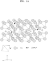
- FIG. 1A is a schematic diagram showing the crystal structure of a mixed solid-state ionic conductor according to an embodiment
- FIG. 1B is a schematic diagram showing the crystal structure of a mixed solid-state ionic conductor according to an embodiment.
- FIG. 2 is a schematic diagram showing a unit cell in the crystal structure of a mixed solid-state ionic conductor according to an embodiment.
- the mixed solid-state ionic conductor has a distorted rock-salt type crystal structure.
- the distorted rock-salt type crystal structure herein may refer to a crystal structure that is similar to the rock salt structure but has undergone distortions or deviations from the ideal arrangement of a rock-salt crystal structure.
- the rock-salt crystal structure is a cubic close-packed arrangement of ions, where each cation is surrounded by anions, and vice versa, in a regular and repeating pattern.
- external factors such as temperature, pressure, or the presence of impurities can cause the crystal lattice to deviate from this ideal cubic arrangement.
- the compound of Formula 1 has an octahedral structure in which M' is a central metal cation coordinated by six halogen anions, wherein each halogen anion is optionally substituted with one or more of Y' or Z.
- the M" metal cation and (PO 4 ) 3- anion are located along with the M (alkali metal), e.g., Li metal cation, in the space around the octahedron.
- the Li metal cation may have a LiX ionic bond depending on the distance between the same from the X halogen anion.
- M'X and/or Li 3 (PO 4 ) impurities may also be produced.
- the mixed solid-state ionic conductor may have a layered crystal structure.
- the mixed solid-state ionic conductor has a lithium ion movement channel connected three-dimensionally in a three-dimensional area in the x-axis, y-axis, and z-axis directions, and the salt of Formula 2 is a nano-sized particle and acts as a filler in the space around the compound of Formula 1. Therefore, it is considered that the ionic conductivity of the mixed solid-state ionic conductor is improved and the charge and discharge characteristics are improved.
- the amount of the salt of Formula 2 may be about 5 wt% to about 30 wt%, about 8 wt% to about 25 wt%, or about 10 wt% to about 20 wt%, based on 100 wt% of the total weight of the mixed solid-state ionic conductor.
- the amount of the salt of Formula 2 is within this range, ionic conductivity and charging and discharging characteristics may be further improved.
- a major peak appears at a location where the diffraction angle 2 ⁇ is about 15°2 ⁇ to about 25°2 ⁇ , about 17°2 ⁇ to about 23°2 ⁇ , or about 19°2 ⁇ to about 21°2 ⁇
- a minor peak appears at a location where the diffraction angle 2 ⁇ is about 25°2 ⁇ to about 35°2 ⁇ , about 27°2 ⁇ to about 33°2 ⁇ , or about 29°2 ⁇ to about 31°2 ⁇ .
- the major peak refers to the peak with the maximum intensity
- the minor peak refers to the peak with a smaller intensity compared to the major peak.
- the mixed solid-state ionic conductor may have the ionic conductivity of about 8.0 ⁇ 10 -4 Siemens per centimeter (S cm -1 ) to about 3.0 ⁇ 10 -3 S cm -1 , about 9.0 ⁇ 10 -4 S cm -1 to about 3.0 ⁇ 10 -3 S cm -1 , or about 1.0 ⁇ 10 -3 S cm -1 to about 3.0 ⁇ 10 -3 S cm -1 , at 25 °C.
- the mixed solid-state ionic conductor may have an activation energy of about 0.1 electron Volt (eV) to about 0.35 eV, about 0.15 eV to about 0.3 eV, or about 0.2 eV to about 0.25 eV, at 25 °C.
- eV electron Volt
- Solid-state electrolyte cathode, and electrochemical device
- a solid-state electrolyte may include the mixed solid-state ionic conductor as described above.
- the solid-state electrolyte including the mixed solid-state ionic conductor may provide electrochemical devices with improved ionic conductivity and improved charging and discharging characteristics.
- the solid-state electrolyte may be in a powder or a molded form.
- the molded product of the solid-state electrolyte may have the form of pellets, sheets, thin films, etc.
- the solid-state electrolyte may be in the form of pellets.
- the molded product of the solid-state electrolyte is not limited thereto and may be manufactured in various forms depending on the purpose.
- a cathode may include the mixed solid-state ionic conductor as described above.
- an electrochemical device may include the solid-state electrolyte as described above in at least one of a cathode layer, an anode layer, and the solid-state electrolyte layer.
- an electrochemical device comprises: a cathode layer; an anode layer; and a solid-state electrolyte layer between the cathode layer and the anode layer, wherein the solid-state electrolyte is in at least one of the cathode layer, the anode layer, or the solid-state electrolyte layer.
- the electrochemical device may be an electrochemical cell, a storage battery, a supercapacitor, a fuel cell, a sensor, or a color changing device.
- the electrochemical device may be an electrochemical cell.
- the electrochemical cell may be an all-solid-state secondary battery.
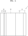
- FIGS. 3 to 5 are cross-sectional views of an all-solid-state secondary battery 1 or 1a according to an embodiment.
- the all-solid-state secondary battery 1 or 1a includes a cathode layer 10 including a cathode current collector 11 and a cathode active material layer 12, an anode layer 20, and a solid-state electrolyte layer 30 disposed between the cathode layer 10 and the anode layer 20.
- the anode layer 20 includes an anode current collector 21 and an anode active material layer 22 disposed on the anode current collector 21, wherein the anode active material layer 22 may include lithium metal or an anode active material that forms an alloy with lithium.
- One or more of the cathode layer 10, the anode layer 20, or the solid-state electrolyte layer 30, of the all-solid-state secondary battery 1 or 1a may include the solid-state ionic conductor as described above.
- the cathode layer 10 may include the mixed solid-state ionic conductor as described above and the solid-state electrolyte layer 30 may include a solid-state electrolyte of a sulfide-based solid-state electrolyte, an oxide-based solid-state electrolyte, a polymer solid-state electrolyte, or a combination thereof.
- the cathode layer 10 includes the mixed solid-state ionic conductor as described above, and the solid-state electrolyte layer 30 may further include, in addition to the mixed solid-state ionic conductor as described above, a different solid-state electrolyte of a sulfide-based solid-state electrolyte, an oxide-based solid-state electrolyte, a polymer solid-state electrolyte, or a combination thereof.
- the cathode layer comprises the solid-state electrolyte
- the solid-state electrolyte layer comprises a first solid-state electrolyte comprising the solid-state electrolyte, and a second solid-state electrolyte comprising a sulfide-containing solid-state electrolyte, an oxide-containing solid-state electrolyte, a polymer solid-state electrolyte, or a combination thereof.
- a metal substrate may be used as the cathode current collector 11.
- metal substrates include a plate or foil which includes indium (In), copper (Cu), magnesium (Mg), stainless steel, titanium (Ti), iron (Fe), cobalt (Co), nickel (Ni), zinc (Zn), aluminum (Al), germanium (Ge), lithium (Li), an alloy thereof, or a combination thereof.
- the cathode current collector 11 may be omitted.
- the cathode active material layer 12 is a layer derived from a composition including a cathode active material andr a solid-state electrolyte.
- the solid-state electrolyte included in the cathode layer 10 may be the same as or different from the solid-state electrolyte included in the solid-state electrolyte layer 30.
- the cathode active material layer 12 may include the solid-state electrolyte including the mixed solid-state ionic conductor as described above.
- the cathode active material may be used without limitation as long as it can be suitably used in the all-solid-state secondary batteries 1 and 1a.
- the cathode active material one or more of composite oxides of lithium and a metal of cobalt, manganese, nickel, or a combination thereof may be used.
- Li a A 1-b B' b D' 2 (where 0.90 ⁇ a ⁇ 1.8 and 0 ⁇ b ⁇ 0.5); Li a E 1-b B' b O 2-c D' c (where 0.90 ⁇ a ⁇ 1.8, 0 ⁇ b ⁇ 0.5, and 0 ⁇ c ⁇ 0.05); LiE 2-b B' b O 4-c D' c (where 0 ⁇ b ⁇ 0.5 and 0 ⁇ c ⁇ 0.05); Li a Ni 1-b-c Co b B' c D' ⁇ (where 0.90 ⁇ a ⁇ 1.8, 0 ⁇ b ⁇ 0.5, 0 ⁇ c ⁇ 0.05, and 0 ⁇ ⁇ ⁇ 2); Li a Ni 1-b-c Co b B' c O 2- ⁇ F' ⁇ (where 0.90 ⁇ a ⁇ 1.8, 0 ⁇ b ⁇ 0.5, 0 ⁇ c ⁇ 0.05, and
- A may be Ni, Co, Mn, or a combination thereof;
- B' may be Al, Ni, Co, Mn, Cr, Fe, Mg, Sr, V, a rare earth element, or a combination thereof;
- D' may be O, F, S, P, or a combination thereof;
- E may be Co, Mn, or a combination thereof;
- F' may be F, S, P, or a combination thereof;
- G may be Al, Cr, Mn, Fe, Mg, La, Ce, Sr, V, or a combination thereof;
- Q may be Ti, Mo, Mn, or a combination thereof;
- the cathode active material includes one or more of lithium cobalt oxide, lithium nickel oxide, lithium nickel cobalt oxide, lithium nickel cobalt aluminum oxide, lithium nickel cobalt manganese oxide, lithium manganese oxide, lithium iron phosphate, nickel sulfide, copper sulfide, lithium sulfide, iron oxide, or vanadium oxide.
- the cathode active material layer 12 may further include an ionic liquid electrolyte.
- Ionic liquid electrolytes may be non-volatile.
- the ionic liquid refers to a salt that is in a liquid state at room temperature or a molten salt at room temperature, which has a melting point below room temperature and consists only of ions.
- the ionic liquid may be one of compounds including: a) one or more cations of an ammonium-based cation, a pyrrolidinium-based cation, a pyridinium-based cation, a pyrimidinium-based cation, an imidazolium-based cation, a piperidinium-based cation, a pyrazolium-based cation, an oxazolium-based cation, a pyridazinium-based cation, a phosphonium-based cation, a sulfonium-based cation, a triazolium-based cation, or mixtures thereof; and b) one or more of anions of BF 4 - , PF 6- , AsF 6 -, SbF 6 - , AlCl 4 - , HSO 4 - , ClO 4 - , CH 3 SO 3 - , CF 3 CO 2 -
- a polymer ionic liquid may include a repeating unit including: a) one or more cations of an ammonium-based cation, a pyrrolidinium-based cation, a pyridinium-based cation, a pyrimidinium-based cation, an imidazolium-based cation, a piperidinium-based cation, a pyrazolium-based cation, an oxazolium-based cation, a pyridazinium-based cation, a phosphonium-based cation, a sulfonium-based cation, a triazolium-based cation, or mixtures thereof; and b) one or more anions of BF 4 - , PF 6 - , AsF 6 - , SbF 6 - , AlCl 4 - , HSO 4 - , ClO 4 - , CH 3 SO 3 - ,
- the ionic liquid electrolyte may fill the pores of the surface of the cathode active material layer 12 in contact with the solid-state electrolyte layer 30 .
- the amount of the ionic liquid electrolyte may be about 0.1 parts by weight to about 20 parts by weight, about 0.1 parts by weight to about 15 parts by weight, about 0.1 parts by weight to about 10 parts by weight, or about 0.1 parts by weight to about 5 parts by weight, based on 100 parts by weight of the cathode active material layer 12 not including the ionic liquid electrolyte.
- the cathode active material layer 12 may further include a conductive material, or a binder.
- the conductive material may include carbon black, carbon fiber, graphite, or a combination thereof.
- the carbon black may be acetylene black, Ketjen black, Super P carbon, channel black, furnace black, lamp black, thermal black, or a combination thereof.
- Graphite may be natural graphite or artificial graphite. Combinations including at least two of the foregoing materials may be used.
- the cathode active material layer 12 may additionally include a conductive material of a different composition in addition to the conductive material as described above.
- Additional conductive materials include electrically conductive fibers such as metal fibers; fluorocarbon powder; metal powders such as aluminum powder or nickel powder; conductive whiskers such as zinc oxide or potassium titanate; polyethylene derivatives; or a combination thereof.
- the amount of the conductive material may be in the range of about 1 part by weight to about 10 parts by weight, for example, about 2 parts by weight to about 7 parts by weight, based on 100 parts by weight of the cathode active material. When the amount of the conductive material is within this range, for example, about 1 part by weight to about 10 parts by weight, the electrical conductivity of the cathode layer 10 may be adequate.
- the binder may improve the adhesion between the components of the cathode layer 10 and the adhesion to the cathode current collector 11.
- binders include polyacrylic acid (PAA), polyvinylidene fluoride, polyvinyl alcohol, carboxymethyl cellulose (CMC), starch, and hydroxypropyl cellulose, regenerated cellulose, polyvinylpyrrolidone, polytetrafluoroethylene, polyethylene, polypropylene, ethylene-propylene-diene monomer (EPDM), sulfonated EPDM, styrene-butadiene-rubber, fluorinated rubber, copolymers thereof, or combinations thereof.
- PAA polyacrylic acid
- CMC carboxymethyl cellulose
- EPDM ethylene-propylene-diene monomer
- EPDM ethylene-propylene-diene monomer
- EPDM ethylene-propylene-diene monomer
- sulfonated EPDM styrene-buta
- the amount of the binder may be in the range of about 1 part by weight to about 10 parts by weight, for example, in the range of about 2 parts by weight to about 7 parts by weight, based on 100 parts by weight of the cathode active material.
- the amount of the binder is within this range, the adhesion of the cathode active material layer 12 to the cathode current collector 11 is further improved, and a decrease in the energy density of the cathode active material layer 12 may be suppressed.
- Solvents such as N-methylpyrrolidone, acetone, and water may be used.
- the amounts of the cathode active material, the conductive material, the binder, and the solvent are at levels suitably used in all-solid-state secondary batteries.
- the cathode active material layer 12 may be prepared by appropriately mixing additives such as fillers, dispersants, and ion conductivity auxiliaries, in addition to the cathode active material, the solid-state electrolyte, the conductive material, and the binder, which are as described above. If necessary, a plasticizer may be added to the composition to form pores inside the cathode active material layer 12. As fillers, dispersants, ion conductive auxiliaries, plasticizers, etc., known materials generally used in electrodes of all-solid-state secondary batteries 1 and 1a may be used.
- the anode layer 20 may include the anode current collector 21 and the anode active material layer 22.
- Materials constituting the anode current collector 21 include copper (Cu), stainless steel, titanium (Ti), iron (Fe), cobalt (Co), or nickel (Ni).
- the anode current collector 21 may include one type of metal, or an alloy or a coating material of two or more of metals.
- the anode current collector 21 may be formed, for example, in a plate shape or a foil shape.
- the anode active material layer 22 may include lithium metal or lithium alloy. Examples of lithium alloys may include lithium and one or more of gold, platinum, palladium, silver, aluminum, bismuth, tin, or zinc. If necessary, the anode active material layer 22 may include a carbon-based (i.e., carbon-containing) anode active material, or an anode active material including a combination of lithium metal or lithium alloy and a carbon-based anode active material.
- a carbon-based (i.e., carbon-containing) anode active material or an anode active material including a combination of lithium metal or lithium alloy and a carbon-based anode active material.
- Carbon-based anode active materials include graphite, carbon black (CB), acetylene black (AB), furnace black (FB), ketjen black (KB), graphene, carbon nanotubes, or carbon nanofiber.
- the anode active material layer 22 may be formed by appropriately mixing additives such as conductive materials, binders, fillers, dispersants, and ionic conductivity auxiliaries including the same materials as those described in the cathode layer 10.
- the anode active material layer 22 may be an anode-free coating layer.
- the anode-free coating layer may contain a metal such as silicon and carbon, and may have a structure in which a conductive binder is disposed around the metal and carbon.
- a thickness of the anode-free coating layer may be 1 ⁇ m to 20 ⁇ m.
- the solid-state electrolyte layer 30 may include the mixed solid-state ionic conductor as described above.
- the solid-state electrolyte layer 30 may further include an oxide-based solid-state electrolyte, a sulfide-based solid-state electrolyte, a polymer solid-state electrolyte, or a combination thereof.
- the solid-state electrolyte layer 30 comprises a first solid-state electrolyte comprising the solid-state electrolyte, and a second solid-state electrolyte comprising a sulfide-containing solid-state electrolyte, an oxide-containing solid-state electrolyte, a polymer solid-state electrolyte, or a combination thereof.
- the cathode layer comprises the solid-state electrolyte
- the solid-state electrolyte layer 30 comprises a first solid-state electrolyte comprising the solid-state electrolyte, and a second solid-state electrolyte comprising a sulfide-containing solid-state electrolyte, an oxide-containing solid-state electrolyte, a polymer solid-state electrolyte, or a combination thereof.
- the solid-state electrolyte layer 30 may be a single layer or a multi-layer of two or more layers.
- the solid-state electrolyte layer 30 may be a two-layer solid-state electrolyte layer including a first solid-state electrolyte layer which is positioned in contact with the cathode layer 10 and a second solid-state electrolyte layer on the first solid-state electrolyte layer.
- the first solid-state electrolyte layer may be the mixed solid-state ionic conductor as described above
- the second solid-state electrolyte layer may be an oxide-based solid-state electrolyte, a sulfide-based solid-state electrolyte, a polymer solid-state electrolyte, or a combination thereof.
- the first solid-state electrolyte layer may be an oxide-based solid-state electrolyte, a sulfide-based solid-state electrolyte, a polymer solid-state electrolyte, or a combination thereof
- the second solid-state electrolyte layer may be the mixed solid-state ionic conductor as described above.
- An example of an oxide-based solid-state electrolyte may include one or more of Li 1+x+y Al x Ti 2-x Si y P 3-y O 12 (0 ⁇ x ⁇ 2, 0 ⁇ y ⁇ 3), BaTiOs, Pb(Zr,Ti)O 3 (PZT), Pb 1-x La x Zr 1-y Ti y O 3 (PLZT) (0 ⁇ x ⁇ 1, 0 ⁇ y ⁇ 1), Pb(Mg 1/3 Nb 2/3 )O 3 -PbTiO 3 (PMN-PT), HfO 2 , SrTiOs, SnO 2 , CeO 2 , Na 2 O, MgO, NiO, CaO, BaO, ZnO, ZrO 2 , Y 2 O 3 , Al 2 O 3 , TiO 2 , SiO 2 , Li 3 PO 4 , Li x Ti y (PO 4 ) 3 (0 ⁇ x ⁇ 2, 0 ⁇ y ⁇ 3), LixAlyTiz(PO 4 ) 3 (0 ⁇
- Oxide-based solid-state electrolytes may be prepared by a sintering method, a casting method, etc.
- the oxide-based solid-state electrolyte may be a garnet-based solid-state electrolyte.
- the garnet-based solid-state electrolyte may include an oxide represented by Formula 5, Formula 5 (Li x M'1 y )(M'2) 3- ⁇ (M'3) 2- ⁇ O 12-z X' z wherein in the formula, 6 ⁇ x ⁇ 8, 0 ⁇ y ⁇ 2, -0.2 ⁇ 0.2, -0.2 ⁇ 0.2, and 0 ⁇ z ⁇ 2,
- examples of monovalent cations include Na, K, Rb, Cs, H, Fr, etc.
- examples of divalent cations include Mg, Ca, Ba, Sr, etc.
- examples of trivalent cations are In, Sc, Cr, Au, B, Al, and Ga
- examples of tetravalent cations in Formula 1 are Sn, Ti, Mn, Ir, Ru, Pd, Mo, Hf, Ge, V, and Si.
- examples of pentavalent cations are Nb, Ta, Sb, V, and P.
- M'1 may be, for example, hydrogen (H), iron (Fe), gallium (Ga), aluminum (Al), boron (B), beryllium (Be), or a combination thereof.
- M'2 may be lanthanum (La), barium (Ba), calcium (Ca), strontium (Sr), yttrium (Y), bismuth (Bi), praseodymium (Pr), neodymium (Nd), actinium (Ac), samarium (Sm), gadolinium (Gd), or a combination thereof
- M'3 may be zirconium (Zr), hafnium (Hf), tin (Sn), niobium (Nb), titanium (Ti), vanadium (V), chromium (Cr), manganese (Mn), cobalt (Co), nickel (Ni), copper (Cu), molybdenum (Mo), tungsten (W), tantalum (Ta), magnesium (Mg), technetium
- the monovalent anion used as X' may be a halogen atom, a pseudohalogen, or a combination thereof, the divalent anion may be S 2- or Se 2- , and the trivalent anion may be, for example, N 3- .
- the garnet-based solid-state electrolyte may include an oxide represented by Formula 6, Formula 6 (Li x M'1 y )(La a1 M'2 a2 ) 3- ⁇ (Zr b1 M'3 b2 ) 2- ⁇ O 12-z X' z wherein in the formula, M'1 may be hydrogen (H), iron (Fe), gallium (Ga), aluminum (Al), boron (B), beryllium (Be), or a combination thereof,
- the monovalent anion used as X' may be a halogen atom, a pseudohalogen, or a combination thereof, the divalent anion may be S 2- or Se 2- , and the trivalent anion may be, for example, N 3- .
- pseudohalogen used herein is a molecule comprised of two or more electronegative atoms that are similar to halogens in the free state, and may generate anions that are similar to halide ions.
- pseudohalogens are cyanide, cyanate, thiocyanate, azide, or a combination thereof.
- Halogen atoms may be, for example, iodine (I), chlorine (CI), bromine (Br), fluorine (F), or a combination thereof, and pseudohalogens may be, for example, cyanide, cyanate, thiocyanate, azide, or a combination thereof.
- the trivalent anion may be, for example, N 3- .
- a garnet-based solid-state electrolyte may be an oxide represented by Formula 7, Formula 7 Li 3+x La 3 Zr 2-a (M'4) a O 12 wherein M'4 in Formula 7 may be Al, Ga, In, Si, Ge, Sn, Sb, Bi, Sc, Y, Ti, Hf, V, Nb, Ta, W, or a combination thereof, and x may be a number from 1 to 10, and 0 ⁇ a ⁇ 2.
- garnet-based solid-state electrolytes are Li 7 La 3 Zr 2 O 12 , and Li 6.5 La 3 Zr 1.5 Ta 0.5 O 12 .
- the garnet-based solid-state electrolyte may have an ionic conductivity of 1 mSc ⁇ cm -1 or greater and may be prepared in the form of pellets, tapes, and films.
- the garnet-based solid-state electrolyte may be prepared to have various thicknesses over a wide temperature range.
- the sulfide-based solid-state electrolyte is not particularly limited as long as it includes sulfur (S) or sulfur-based elements (Se, Te) and has ionic conductivity.
- the sulfide-based solid-state electrolyte may include one or more of Li 2 S-P 2 S 5 , Li 2 S-P 2 S 5 -LiX (where X is a halogen element), Li 2 S-P 2 S 5 -Li 2 O, Li 2 S-P 2 S 5 -Li 2 O-Lil, Li 2 S-SiS 2 , Li 2 S-SiS 2 -LiI, Li 2 S-SiS 2 -LiBr, Li 2 S-SiS 2 -LiCl, Li 2 S-SiS 2 -B 2 S 3 -LiI, Li 2 S-SiS 2 -P 2 S 5 -LiI, Li 2 S-B 2 S 3 , Li 2 S-P 2 S 5 -Z
- a sulfide-based solid-state electrolyte material includes Li 2 S-P 2 S 5
- the mixing molar ratio of Li 2 S and P 2 S 5 may be selected in the range of 50:50 to 90:10, may be selected in the range of 60:40 to 90:10, or may be selected in the range of 75:25 to 90:10.
- the sulfide-based solid-state electrolyte may be prepared by treating raw starting materials (for example, Li 2 S, P 2 S 5 , etc.) by a melt quenching method, a mechanical milling method, etc. In some embodiments, calcinations may be performed after the treatment.
- the sulfide-based solid-state electrolyte may include a compound represented by Formula 8, Formula 8 Li a M'5 x PS y M'6 z M'7 w wherein in Formula 8, M'5 may be one or more metal elements other than Li of Group 1 to Group 15 of the Periodic Table, and M'6 may be one or more elements of Group 17 of the Periodic Table, and
- M'7 may be SO n , 4 ⁇ a ⁇ 8, 0 ⁇ x ⁇ 1, 3 ⁇ y ⁇ 7, 0 ⁇ z ⁇ 5, 0 ⁇ w ⁇ 2, and 1.5 ⁇ n ⁇ 5.
- M'5 may include Na, K, Mg, Ag, Cu, Hf, In, Ti, Pb, Sb, Fe, Zr, Zn, Cr, B, Sn, Ge, Si, Zr, Ta, Nb, V, Ga, Al, As, or a combination thereof.
- M'5 may be, for example, a monovalent cation or a divalent cation.
- M'6 may include F, Cl, Br, I, or a combination thereof.
- M'6 may be, for example, a monovalent anion.
- SO n of M7 may be S 4 O 6 , S 3 O 6 , S 2 O 3 , S 2 O 4 , S 2 O 3 , S 2 O 6 , S 2 O 7 , S 2 O 3 , SO 4 , SOs, or a combination thereof.
- SO n may be, for example, a divalent anion.
- SO n 2- may be, for example, S 4 O 6 2- , S 3 O 6 2- , S 2 O 3 2- , S 2 O 4 2- , S 2 O 3 2- , S 2 O 3 2- , S 2 O 7 2- , S 2 O 8 2- , SO 4 2- , SO 5 2- , or a combination thereof.
- the compound represented by Formula 8 may be a compound selected from compounds represented by Formulae 8a to 8b: Formula 8a Li a PS y M"7 z M'8 w wherein in Formula 8a, M"7 may be one or more elements of Group 17 of the Periodic Table, M'8 may be SO n , and 4 ⁇ a ⁇ 8, 3 ⁇ y ⁇ 7, 0 ⁇ z ⁇ 5, 0 ⁇ w ⁇ 2, and 1.5 ⁇ n ⁇ 5, Formula 8b Li a M'9 x PS y M'10 z M'11 w wherein in Formula 8b, M'9 may be one or more metal elements other than Li of Group 1 to Group 15 of the Periodic Table, and M'10 may be one or more elements of Group 17 of the Periodic Table, and M'11 may be SO n , 4 ⁇ a ⁇ 8, 0 ⁇ x ⁇ 1, 3 ⁇ y ⁇ 7, 0 ⁇ z ⁇ 5, 0 ⁇ w ⁇ 2, and 1.5 ⁇ n ⁇ 5.
- Formulae 8a and 8b 0 ⁇ z ⁇ 5, 0 ⁇ z ⁇ 4, 0 ⁇ z ⁇ 3, 0 ⁇ z ⁇ 2, 0.2 ⁇ z ⁇ 1.8, 0.5 ⁇ z ⁇ 1.8, 1.0 ⁇ z ⁇ 1.8 or 1.0 ⁇ z ⁇ 1.5.
- Formulae 8a and 8b for example, 5 ⁇ a ⁇ 8, 4 ⁇ y ⁇ 7, 0 ⁇ z ⁇ 2, and 0 ⁇ w ⁇ 0.5; 5.5 ⁇ a ⁇ 7, 4.5 ⁇ y ⁇ 6, 0.2 ⁇ z ⁇ 1.8, and 0 ⁇ w ⁇ 0.1; 0.5 ⁇ z ⁇ 1.8; or 1.0 ⁇ z ⁇ 1.8.
- the compound represented by Formula 8 may be a compound represented by Formula 9, Formula 9 Li 7-m ⁇ v-z M'12 v PS 6-z M'13 z1 M'14 z2
- M'12 may be Na, K, Mg, Ag, Cu, Hf, In, Ti, Pb, Sb, Fe, Zr, Zn, Cr, B, Sn, Ge, Si, Zr, Ta, Nb, V, Ga, Al, As, or a combination thereof
- M'12 may be, for example, one metal element or two metal elements.
- the compound represented by Formula 9 may contain one type of halogen element or two types of halogen elements.
- the compound represented by Formula 9 may be a solid-state ionic conductor compound represented by Formulae 9a to 9f: Formula 9a Li 7-z PS 6-z M'15 z1 M'16 z2 Formula 9b Li 7-v-z Na v PS 6-z M'15 z1 M'16 z2 Formula 9c Li 7-v-z K v PS 6-z M'15 z1 M'16 z2 Formula 9d Li 7-v-z CU v PS 6-z M'15 z1 M'16 z2 Formula 9e Li 7-v-z Mg v PS 6-z M'15 z1 M'16 z2 Formula 9f Li 7-v-z Ag v PS 6-z M'15 z1 M'16 z2
- v 0.
- the compound represented by Formula 8 may be, for example, a compound represented by one of the following formulae:
- the compound represented by Formula 8 may belong to, for example, a cubic crystal system and, more specifically, to the F-43m space group. Additionally, the compound represented by Formula 8 may be an argyrodite-type sulfide having an argyrodite-type crystal structure.
- the compound represented by Formula 8 includes, for example, one or more of a monovalent cation element and a divalent cation element substituted for a portion of the lithium site in the argyrodite -type crystal structure, or includes a heterogeneous halogen element, or includes a substituted SO n anion in the halogen site, and thus, lithium ion conductivity may be further improved, and electrochemical stability to lithium metal may be further improved.
- "Argyrodite" or "argyrodite-type” as used herein means that the compound has a crystal structure isostructural with argyrodite, Ag 8 GeS 6 .
- the compound represented by Formula 8 is, for example, Li 6 PS 5 Cl.
- the sulfide-based solid-state electrolyte used herein may be an argyrodite-type compound including one or more of Li 7-x PS 6-x Cl x , 0 ⁇ x ⁇ 2, Li 7-x PS 6-x Br x , 0 ⁇ x ⁇ 2, or Li 7-x PS 6-x I x where x satisfies the condition of 0 ⁇ x ⁇ 2.
- the sulfide-based solid-state electrolyte included in the solid-state electrolyte may be an argyrodite-type compound including one or more of Li 6 PS 5 Cl, Li 6 PS 5 Br, or Li 6 PS 5 I.
- polymer solid-state electrolytes examples include polyethylene oxide, polypropylene oxide, polystyrene (PS), polyphosphazene, polysiloxane, polyvinylidene fluoride-co-hexafluoropropylene (PVDF-HFP), polyacrylonitrile (PAN), or a combination thereof.
- the ionic conductivity of this polymer solid-state electrolyte may be achieved by local segmental motion of the polymer.
- Polymer solid-state electrolytes may be prepared by mixing polyether with plasticizer salts and sometimes some liquid plasticizer. This electrolyte may be prepared into a thin film using a solvent evaporation coating method. However, it is not limited thereto, and any suitable polymer solid-state electrolyte available in the art may be used.
- the solid-state electrolyte layer may further include a binder.
- the binder included in the solid-state electrolyte layer 30 may be, for example, styrenebutadiene rubber (SBR), polytetrafluoroethylene, polyvinylidene fluoride, polyethylene, etc., but is not limited to these.
- the binder may be any suitable material that can be used as a binder in the relevant technical field.
- the solid-state electrolyte layer 30 may be prepared by depositing using a known film formation method such as an aerosol deposition method, a cold spray method, or a sputtering method. In some embodiments, the solid-state electrolyte layer 30 may be prepared by pressing single particles of the solid-state electrolyte. In some embodiments, the solid-state electrolyte layer 30 may be prepared by mixing a solid-state electrolyte, a solvent, and a binder, applying the mixture, and drying and pressing.
- a known film formation method such as an aerosol deposition method, a cold spray method, or a sputtering method.
- the solid-state electrolyte layer 30 may be prepared by pressing single particles of the solid-state electrolyte.
- the solid-state electrolyte layer 30 may be prepared by mixing a solid-state electrolyte, a solvent, and a binder, applying the mixture, and drying and pressing.
- a plating thin film (e.g., film) 24 may be disposed (e.g., formed) on a surface of the anode current collector 21.
- the thin film 24 may include an element that may form an alloy with lithium. Elements that may form an alloy with lithium may include, for example, gold, silver, zinc, tin, indium, silicon, aluminum, or bismuth.
- the thin film 24 may be composed of one of these metals or may be composed of alloy of several types of metals.
- a precipitation form of a metal layer 23 shown in FIG. 5 may be further flattened, and the characteristics of the all-solid-state secondary battery 1 may be further improved.
- the metal layer 23 shown in FIG. 5 may be formed between the anode current collector 21 and the anode active material layer 22 by overcharging of the anode active material layer 22.
- the metal layer 23 shown in FIG. 5 is previously (i.e. prior to initial charging) formed between the anode current collector 21 and the anode active material layer 22.
- the metal layer 23 shown in FIG. 5 may include lithium or a lithium alloy. That is, the metal layer 23 may function as a lithium reservoir.
- the lithium alloy may be, for example, a Li-Al alloy, a Li-Sn alloy, a Li-In alloy, a Li-Ag alloy, a Li-Au alloy, a Li-Zn alloy, a Li-Ge alloy, a Li-Si alloy, or the like.
- the metal layer 23 shown in FIG. 5 may be formed of one of these alloys or lithium, or an alloy thereof.
- a thickness of the metal layer 23 may be range from about 1 ⁇ m to about 200 ⁇ m, but is not particularly limited. When the thickness of the metal layer 23 less than 1 ⁇ m, the function of the metal layer 23 as a reservoir may not be sufficiently exhibited. When the thickness of the metal layer 23 is greater than 200 ⁇ m, the mass and volume of the all-solid-state secondary battery 1 may be increased, resulting in rather deteriorated characteristics.
- the metal layer 23 may be, for example, metal foil having a thickness within the above-described range.
- a thickness of the thin film 24 may be from about 1 nm to about 500 nm, for example, about 10 nm to about 400 nm, about 30 nm to about 300 nm, or about 50 nm to about 200 nm, but is not limited thereto. When the thickness of the thin film 24 is within this range, the function of the thin film 24 is sufficiently exercised and the amount of lithium precipitated in the anode layer is appropriate, so that the characteristics of the all-solid-state secondary batteries 1 and 1a are improved.
- the thin film 24 may be formed on the anode current collector 21 by, for example, vacuum deposition, sputtering, or plating.
- a method of manufacturing a mixed solid-state ionic conductor includes preparing a precursor and a salt which are for forming a solid-state ionic conductor; providing a precursor mixture for forming a solid-state ionic conductor by performing mechanical milling on the precursor and salt for forming a solid-state ionic conductor; and molding the precursor mixture for forming the solid-state ionic conductor to prepare the mixed solid-state ionic conductor.
- a method of preparing a mixed solid-state ionic conductor comprises:
- the mixed solid-state ionic conductor may include a compound represented by Formula 1 and a salt represented by Formula 2: Formula 1 M a M' b X c Y' d Z e wherein
- the method of manufacturing the mixed solid-state ionic conductor allows the preparation of a solid-state ionic conductor which has improved ionic conductivity, electrochemical stability over a wide potential window when applied as a solid-state electrolyte in an electrochemical device, improved cycle stability with a metal electrode including lithium, and reversible development of the designed cathode capacity.
- an M precursor, an M' precursor, an X precursor, a Y' precursor salt, a Z precursor salt, and the salt of Formula 2 may be mixed together.
- the M precursor may be a precursor of an alkali metal element with an oxidation number of +1
- the M' precursor may be a precursor of a metal element with an oxidation number of +3 or +4.
- the M precursor and M' precursor may include halides such as chlorides, oxides, nitrides, oxynitrides, nitrates, hydroxides, and carbonates of M metal and M' metal, respectively.
- the M' precursor may include chlorides, oxides, nitrides, oxynitrides, nitrates, hydroxides, and carbonates of an element of Ti, Zr, Hf, V, Nb, Ta, Al, Ga, In, La, Ce, Pr, Nd, Pm, Sm, Eu, Gd, Tb, Dy, Ho, Er, Tm, Yb, Y, Lu, or a combination thereof.
- the M' precursor may include chlorides of Ti, Zr, Hf, V, Nb, Ta, Al, Ga, In, La, Ce, Pr, Nd, Pm, Sm, Eu, Gd, Tb, Dy, Ho, Er, Tm, Yb, Y, Lu, or a combination thereof.
- the Y' precursor salt may be a salt including one or more of anion of SO 3 - , CH 3 COO - , CN - , NO 3 - , NO - , H 2 PO 4 - , PF 6 -, OH-, BF 4 - , N(CF 3 SO 2 ) 2 - , CF 3 CO 2 - , CF 3 SO 3 - , C(CF 3 SO 2 ) 3 - , HCO 3 - , ClO 4 - , HSO 4 - , or SCN - .
- the Z precursor salt may be a salt that includes one or more of anions of (BO 4 ) 3- , (BO 3 ) 3- , (PO 4 ) 3- , [Fe(CN) 6 ] 3- , or [Ag(S 2 O 3 ) 2 ] 3- .
- M which is the cation of the salt of Formula 2
- M' may be the same metal cation as M' in Formula 1 or a different metal cation having a difference in ionic radius from M' within ⁇ 10%.
- the precursors and salts for forming a solid-state ionic conductor may be brought in an appropriate amount, for example, a stoichiometric amount into contact to prepare a mixture. Mechanical milling is performed on the mixture.
- the mechanical milling may be performed using ball-mill, airjet-mill, bead mill, roll-mill, planetary mill, hand milling, high energy ball mill, planetary mill ball mill, stirred ball mill, vibrating mill, mechanofusion milling, shaker milling, planetary milling, attritor milling, disk milling, shape milling, nauta milling, nobilta milling, high speed mix, or a combination thereof.
- the mechanical milling may be planetary milling and may be performed at room temperature. Molding may be further included after the mechanical milling is performed.
- a resting process may be further included.
- the resting process may be performed at room temperature for 1 minute to 10 minutes.
- Example 1 Preparation of mixed solid-state ionic conductor of 6Li 2 ZrCl 6 and Zr 3 (PO 4 ) 4
- ZrCl 4 and Li 3 (PO 4 ) were added to the reactor in a stoichiometric ratio of 9:4 and mixed to prepare a precursor mixture for forming a solid-state ionic conductor.
- the precursor mixture for forming the solid-state ionic conductor was repeatedly mixed at 600 rotations per minute (rpm) for 15 minutes using a planetary mill (Pulverisette 7 premium line) into which 10 millimeters (mm) diameter zirconia (YSZ) balls were loaded, and rested for 5 minutes. This cycle was carried out for a total of 24 hours to obtain a precursor mixture.
- the precursor mixture was placed in a pelletizer with a diameter of 1 inch, and a weight of 5 tons was applied thereto for 2 minutes using uniaxial pressure to produce a circular disk-shaped mixed solid-state ionic conductor pellet of 6Li 2 ZrCl 6 and Zr 3 (PO 4 ) 4 (pellet).
- Example 2 Preparation of mixed solid-state ionic conductor of 4.75Li 2 ZrCl 6 , 0.75Zr 3 (PO 4 ) 3 , and 0.25 ZrCl 4 impurity
- Example 3 Preparation of mixed solid-state ionic conductor of 15LiTaCl 6 and Ta 3 (PO 4 ) 5
- Example 4 Preparation of mixed solid-state ionic conductor of Li 3 YCl 6 and YPO 4
- Example 5 Preparation of mixed solid-state ionic conductor of Li 2 ZrCl 6 , Zr 3 (PO 4 ) 4 , and LaPO 4
- Comparative Example 1 Production of solid-state ionic conductor of Li 2 ZrCl 6
- Solid-state ionic conductor pellets of Li 2 ZrCl 6 were prepared in the same manner as in Example 1, except that ZrCl 4 and LiCI were adjusted to be in a stoichiometric ratio of 1:2 in the reactor.
- Solid-state ionic conductor pellets of LiTaCl 6 were prepared in the same manner as in Example 1, except that TaCls and LiCI were adjusted to be in a stoichiometric ratio of 1:1 in the reactor.
- Solid-state ionic conductor pellets of Li 3 YCl 6 were prepared in the same manner as in Example 1, except that YCl 3 and LiCI were adjusted to be in a stoichiometric ratio of 1:3 in the reactor.
- Solid-state ionic conductor pellets of Li 3 PO 4 were prepared in the same manner as in Example 1, except that Li 3 (PO 4 ) was added to the reactor.
- Comparative Example 5 Preparation of mixed solid-state ionic conductor of Li 2 ZrCl 6 and Li 1.3 Al 0.3 Ti 1.7 (PO 4 ) 3
- Solid-state ionic conductor pellets were prepared in the same manner as in Example 1, except that LiCl, HoCl 3 , and ZrCl 4 were adjusted to be in a stoichiometric ratio of 2.2:0.2:0.8 in the reactor.
- Solid-state ionic conductor pellets were prepared in the same manner as in Example 1, except that Li 2 S, P 2 S 5 , and LiCI were adjusted to be in a stoichiometric ratio of 5:1:2 in the reactor.
- Comparative Example 8 Preparation of mixed solid-state ionic conductor of 6Li 2 ZrCl 6 , Zr 3 (PO 4 ) 4 , and Li 3 PO 4 impurity
- Comparative Example 10 Preparation of mixed solid-state ionic conductor of 8Li 2 ZrCl 6 and Ca 3 (PO 4 ) 2
- a 10 ⁇ m thick copper current collector was placed on the bottom of a tubular cell case with an inner diameter of 13 mm, and a 20 ⁇ m thick indium (In)-deposited foil was placed on a surface of the copper current collector to prepare an anode layer.
- Li 6 PS 5 Cl solid-state ionic conductor pellets (Mitusi, S33) were placed as a first solid-state electrolyte layer and the pressure was evenly distributed thereon.
- 30 mg of the mixed solid-state ionic conductor pellet of 6Li 2 ZrCl 6 and Zr 3 (PO 4 ) 4 prepared in Example 1 was placed as a second solid-state electrolyte layer and the pressure was evenly distributed thereon, and then, 250 megaPascals (MPa) was applied at 25°C by cold isostatic pressing (CIP) to prepare a stack having a copper current collector layer/indium (In) layer/Li 6 PS 5 Cl first solid-state electrolyte layer/6Li 2 ZrCl 6 and Zr 3 (PO 4 ) 4 second solid-state electrolyte layer (thickness: about 300 ⁇ m).
- NCM LiNi 0.9 Co 0.07 Mn 0.03 O 2
- CNF carbon nanofiber
- the cathode layer was placed on the stack of the anode layer/solid-state electrolyte layer and a weight of 4 tons was applied thereon for 2 minutes to manufacture a torque cell type all-solid-state secondary battery.
- All-solid-state secondary batteries were manufactured in the same manner as in Example 6, except that the mixed solid-state ionic conductor pellets prepared according to Examples 2 to 5 were used as the second solid-state electrolyte when preparing the stack of the anode layer/solid-state electrolyte layer, and as the solid-state electrolyte when manufacturing the cathode layer.
- the mixed solid-state ionic conductor prepared in Example 1 has a major peak in the area where the diffraction angle 2 ⁇ is 15°2 ⁇ to 25°2 ⁇ , and a minor peak in the area where the diffraction angle 2 ⁇ is 25°2 ⁇ to 35°2 ⁇ . This result was identical to the XRD spectrum of Zr 3 (PO 4 ) 4 .
- the mixed solid-state ionic conductor prepared in Example 1 includes Zr 3 (PO 4 ) 4 .
- a lithium foil with a thickness of 8 millimeters (mm) was placed on a surface of the (mixed) solid-state ionic conductor pellets prepared in Example 1 and Comparative Example 1, and 250 MPa was applied thereon at 25°C by CIP.
- a lithium electrode was attached to another surface of the pellets in the same manner to prepare a lithium symmetry cell with a structure of the lithium/(mixed) solid-state ionic conductor pellet/lithium.
- Current collectors were respectively placed on the lithium electrodes disposed on the surfaces of the pellets, and while sealing the symmetrical cell, a portion of each of the current collectors was protruded outside the sealed symmetrical cell and used as an electrode terminal. The interfacial resistance of the pellets was measured using the prepared symmetric cell.
- the impedance of the symmetrical cell was measured using the 2-probe method using Biologic VMP3 as an impedance analyzer. Impedance measurements were conducted in a dry-room atmosphere with an amplitude of 200 millivolts (mV), a frequency in the range of 1 Hertz (Hz) to 1 megaHertz (MHz), and a dew point of - 60 °C at 25 °C. Interfacial resistance was measured from the size of the arc of the Nyquist plot for the impedance measurement results. Results are shown in FIG. 7 .
- the interfacial resistance of the solid-state ionic conductor prepared in Comparative Example 1 was 430 ⁇ cm 2 or less.
- the interfacial resistance of the mixed solid-state ionic conductor prepared in Example 1 was 120 ⁇ cm 2 or less and was significantly reduced by about 72.1% compared to the solid-state ionic conductor prepared in Comparative Example 1.
- the (mixed) solid-state ionic conductor pellets with a thickness of about 1000 ⁇ m prepared in Example 1 and Comparative Example 1 were prepared.
- Platinum (Pt) paste with a thickness of 20 nm was deposited by sputtering on the two surfaces of the (mixed) solid-state ionic conductor pellets to form a platinum (Pt) electrode.
- Wires were connected to platinum (Pt) electrodes on the surfaces of the specimen, and analysis was performed thereon using electrochemical impedance spectroscopy (EIS).
- EIS electrochemical impedance spectroscopy
- EIS analysis was performed with an amplitude of approximately 10 mV and a frequency ranging from 1 Hz to 10 6 Hz.
- an impedance analyzer a 2-probe (potentiostat/galvanostat and a 1455 frequency response analyzer (FRA) multichannel test module, Solartron Analytical, UK) was used as an impedance analyzer.
- the impedance of the pellet was measured at room temperature (25°C) using the probe method. Resistance values were obtained from the arc of the Nyquist plot for the impedance measurement results, from which conductivity was calculated by correcting the electrode area and pellet thickness. The results are shown in Table 1.
- the ionic conductivity of each of the mixed solid-state ionic conductors prepared by Examples 1-5 was at least 8.1 ⁇ 10 -4 Scm -1 , which is greater than the ionic conductivity of the mixed solid-state ionic conductors prepared by Comparative Examples 5, 8, 9, and 10.
- the ionic conductivity of the mixed solid-state ionic conductor prepared in Example 1 was very high at 2.0 ⁇ 10 -3 Scm -1 .
- the mixed solid-state ionic conductors prepared in Examples 1 to 5 had greater or equal ionic conductivities compared to the halide-based compound solid-state ionic conductors prepared in Comparative Examples 1 to 3, 6, and 7.
- E a the activation energy ( E a ) value for conductivity was calculated from the results measured by changing the temperature of the chamber in which each specimen was loaded.
- E a was calculated from the slope value by converting the conductivity values measured at each temperature in the range of 273 K to 398 K into the Arrhenius plot (Ln (oT) vs. 1/T) of Equation 1.
- conductivity refers to ionic conductivity. Results are shown in FIG. 8 .
- ⁇ T A exp Ea/RT wherein E a is the activation energy, T represents the absolute temperature, A represents the pre-exponential factor, R represents the gas constant, and ⁇ represents the conductivity.
- the activation energy of the solid-state ionic conductor prepared in Comparative Example 1 was 0.36 eV.
- the activation energy of the mixed solid-state ionic conductor prepared in Example 1 was 0.19 eV and was significantly reduced by about 47% compared to the solid-state ionic conductor prepared in Comparative Example 1.
- Example 6 The all-solid-state secondary batteries manufactured in Example 6 and Comparative Example 17 were subjected to charging and discharging experiments in a constant temperature bath at 25 °C as follows.
- Each all-solid-state secondary battery was charged at a constant current of 0.1 C until the battery voltage reached 4.0 V, and was charged at a constant voltage of 4.0 V until the current value reached 0.1 C.
- the C rate is a discharge rate of a cell, and is obtained by dividing a total capacity of the cell by a total discharge period of time of 1 hour, e.g., a C rate for a battery having a discharge capacity of 1.6 ampere-hours would be 1.6 amperes.
- the total capacity is determined by a discharge capacity on the 1st cycle.
- 0.1 C or C/10 refers to a current that will fully discharge the battery in 10 hours.
- the discharge capacity of the all-solid-state secondary battery manufactured in Example 6 was 3.8 mAhcm -2 , which was 0.3 mAhcm -2 greater than that of the all-solid-state secondary battery manufactured in Comparative Example 17.
- the coulombic efficiency of the all-solid-state secondary battery manufactured in Example 6 was about 92% and was about 13% greater than that of the all-solid-state secondary battery manufactured in Comparative Example 17.
- a mixed solid-state ionic conductor includes a compound represented by Formula 1 and a salt represented by Formula 2. Due to the mixing of metal phosphates excluding alkali metals, the mixed solid-state ionic conductor can provide a solid-state electrolyte, a cathode, and an electrochemical device, each of which has, compared to a case where a halide-based solid-state ionic conductor is used alone, higher ionic conductivity, improved charging and discharging characteristics.
Landscapes
- Chemical & Material Sciences (AREA)
- Chemical Kinetics & Catalysis (AREA)
- Electrochemistry (AREA)
- Engineering & Computer Science (AREA)
- General Chemical & Material Sciences (AREA)
- Manufacturing & Machinery (AREA)
- Condensed Matter Physics & Semiconductors (AREA)
- Physics & Mathematics (AREA)
- General Physics & Mathematics (AREA)
- Inorganic Chemistry (AREA)
- Power Engineering (AREA)
- Sustainable Energy (AREA)
- Sustainable Development (AREA)
- Microelectronics & Electronic Packaging (AREA)
- Life Sciences & Earth Sciences (AREA)
- Secondary Cells (AREA)
- Conductive Materials (AREA)
Applications Claiming Priority (1)
| Application Number | Priority Date | Filing Date | Title |
|---|---|---|---|
| KR1020230129565A KR20250046431A (ko) | 2023-09-26 | 2023-09-26 | 혼합 고체이온전도체, 이를 포함하는 고체전해질, 양극, 및 전기화학소자, 및 상기 혼합 고체이온전도체의 제조방법 |
Publications (1)
| Publication Number | Publication Date |
|---|---|
| EP4535489A1 true EP4535489A1 (de) | 2025-04-09 |
Family
ID=92633900
Family Applications (1)
| Application Number | Title | Priority Date | Filing Date |
|---|---|---|---|
| EP24197931.9A Pending EP4535489A1 (de) | 2023-09-26 | 2024-09-02 | Gemischter festkörperionenleiter, festkörperelektrolyt, kathode und elektrochemische vorrichtung damit sowie verfahren zur herstellung des gemischten festkörperionenleiters |
Country Status (4)
| Country | Link |
|---|---|
| US (1) | US20250105345A1 (de) |
| EP (1) | EP4535489A1 (de) |
| KR (1) | KR20250046431A (de) |
| CN (1) | CN119725696A (de) |
Citations (1)
| Publication number | Priority date | Publication date | Assignee | Title |
|---|---|---|---|---|
| US20220223904A1 (en) * | 2021-01-08 | 2022-07-14 | Samsung Electronics Co., Ltd. | Solid ion conductor, solid electrolyte including the solid ion conductor, electrochemical device including the solid electrolyte, and method of preparing the solid ion conductor |
-
2023
- 2023-09-26 KR KR1020230129565A patent/KR20250046431A/ko active Pending
-
2024
- 2024-06-17 US US18/745,104 patent/US20250105345A1/en active Pending
- 2024-09-02 EP EP24197931.9A patent/EP4535489A1/de active Pending
- 2024-09-25 CN CN202411338974.0A patent/CN119725696A/zh active Pending
Patent Citations (1)
| Publication number | Priority date | Publication date | Assignee | Title |
|---|---|---|---|---|
| US20220223904A1 (en) * | 2021-01-08 | 2022-07-14 | Samsung Electronics Co., Ltd. | Solid ion conductor, solid electrolyte including the solid ion conductor, electrochemical device including the solid electrolyte, and method of preparing the solid ion conductor |
Non-Patent Citations (4)
| Title |
|---|
| DARSHAN CHALISE ET AL: "Temperature dependence of 7Li NMR relaxation rates in Li3InCl6, Li3YCl6, Li1.48Al0.48Ge1.52(PO4)3 and LiPS5Cl", ARXIV.ORG, CORNELL UNIVERSITY LIBRARY, 201 OLIN LIBRARY CORNELL UNIVERSITY ITHACA, NY 14853, 22 March 2023 (2023-03-22), XP091466401 * |
| DATABASE COMPENDEX [online] ENGINEERING INFORMATION, INC., NEW YORK, NY, US; 12 October 2010 (2010-10-12), AOKI Y ET AL: "Thickness-induced proton-conductivity transition in amorphous zirconium phosphate thin films", XP002813046, Database accession no. E20104113291658 * |
| ISHIGURO YOSHITAKA ET AL: "TaCl 5 -glassified Ultrafast Lithium Ion-conductive Halide Electrolytes for High-performance All-solid-state Lithium Batteries", CHEMISTRY LETTERS, vol. 52, no. 4, 5 April 2023 (2023-04-05), pages 237 - 241, XP093253859, ISSN: 0366-7022, DOI: 10.1246/cl.220540 * |
| XUMING LUO: "Ionic Conductivity Enhancement of Li 2 ZrCl 6 Halide Electrolytes via Mechanochemical Synthesis for All-Solid-State Lithium-Metal Batteries", APPLIED MATERIALS & INTERFACES, vol. 14, no. 44, 25 October 2022 (2022-10-25), US, pages 49839 - 49846, XP093162990, ISSN: 1944-8244, Retrieved from the Internet <URL:https://pubs.acs.org/doi/pdf/10.1021/acsami.2c14903> [retrieved on 20250225], DOI: 10.1021/acsami.2c14903 * |
Also Published As
| Publication number | Publication date |
|---|---|
| US20250105345A1 (en) | 2025-03-27 |
| KR20250046431A (ko) | 2025-04-03 |
| CN119725696A (zh) | 2025-03-28 |
Similar Documents
| Publication | Publication Date | Title |
|---|---|---|
| EP3813161B1 (de) | Festkörpersekundärbatterie und verfahren zur herstellung einer festkörpersekundärbatterie | |
| EP4002517B1 (de) | Feststoffbatterie und verfahren zur herstellung davon | |
| EP3869584B1 (de) | Festkörpersekundärbatterie und verfahren zur herstellung einer festkörpersekundärbatterie | |
| US11735765B2 (en) | Solid ion conductor, solid electrolyte including the solid ion conductor, electrochemical device including the solid electrolyte, and method of preparing the solid ion conductor | |
| EP4184604A1 (de) | Negativelektrode für festkörpersekundärbatterie, festkörpersekundärbatterie mit negativelektrode und verfahren zur herstellung einer festkörpersekundärbatterie | |
| JP2021132033A (ja) | 全固体二次電池、及び全固体二次電池の製造方法 | |
| EP3817117A1 (de) | Feste ionenleiterverbindung, fester elektrolyt mit fester ionenleiterverbindung, elektrochemische zelle mit fester ionenleiterverbindung und verfahren zur herstellung einer festen ionenleiterverbindung | |
| US12456751B2 (en) | Solid ion conductor compound, solid electrolyte comprising the same, electrochemical cell comprising the same, and method of preparing the same | |
| EP4366020A1 (de) | Festkörperelektrolyt, lithiumbatterie mit dem festkörperelektrolyt und herstellungsverfahren für den festkörperelektrolyt | |
| EP4362140A1 (de) | Anode für eine festkörpersekundärbatterie, festkörpersekundärbatterie damit und verfahren zur herstellung davon | |
| EP3932860A1 (de) | Oxid, herstellungsverfahren dafür, fester elektrolyt mit dem oxid und elektrochemische vorrichtung mit dem oxid | |
| EP4438579A1 (de) | Festkörperelektrolyt, herstellungsverfahren für festkörperelektrolyt und lithiumbatterie mit festkörperelektrolyt | |
| EP4340053A1 (de) | Festkörperbatterie und verfahren zur herstellung davon | |
| EP4376127A1 (de) | Kathode für festkörperbatterie und festkörperbatterie damit | |
| EP4386897A1 (de) | Batterie | |
| US11600855B2 (en) | Solid-state electrolyte, solid-state battery including the electrolyte, and method of making the same | |
| EP4386891A1 (de) | Anoden-festelektrolyt-unteranordnung für festkörpersekundärbatterie, festkörpersekundärbatterie damit und herstellungsverfahren dafür | |
| EP4535489A1 (de) | Gemischter festkörperionenleiter, festkörperelektrolyt, kathode und elektrochemische vorrichtung damit sowie verfahren zur herstellung des gemischten festkörperionenleiters | |
| US12176481B2 (en) | Solid ion conductor, solid electrolyte and electrochemical device including the same, and method of preparing the solid ion conductor | |
| US20250210691A1 (en) | Solid electrolyte, electrochemical device including the solid electrolyte, and method of preparing the solid electrolyte | |
| EP4333114B1 (de) | Negativelektroden-festelektrolyt-unteranordnung, festkörpersekundärbatterie damit und verfahren zur herstellung der festkörpersekundärbatterie | |
| EP4525072A1 (de) | Unterbaugruppe für festkörperbatterie, festkörperbatterie und verfahren zur herstellung einer festkörperbatterie | |
| US20250183301A1 (en) | Sub-assembly for all solid secondary battery, all solid secondary battery, and method of preparing the sub-assembly | |
| EP4343882B1 (de) | Anoden-festelektrolyt-unteranordnung für festkörpersekundärbatterie, festkörpersekundärbatterie mit anoden-festelektrolyt-unteranordnung und verfahren zur herstellung einer anoden-festelektrolyt-unteranordnung | |
| EP4287306A1 (de) | Festkörpersekundärbatterie und verfahren zur herstellung einer festkörpersekundärbatterie |
Legal Events
| Date | Code | Title | Description |
|---|---|---|---|
| PUAI | Public reference made under article 153(3) epc to a published international application that has entered the european phase |
Free format text: ORIGINAL CODE: 0009012 |
|
| STAA | Information on the status of an ep patent application or granted ep patent |
Free format text: STATUS: THE APPLICATION HAS BEEN PUBLISHED |
|
| AK | Designated contracting states |
Kind code of ref document: A1 Designated state(s): AL AT BE BG CH CY CZ DE DK EE ES FI FR GB GR HR HU IE IS IT LI LT LU LV MC ME MK MT NL NO PL PT RO RS SE SI SK SM TR |
|
| STAA | Information on the status of an ep patent application or granted ep patent |
Free format text: STATUS: REQUEST FOR EXAMINATION WAS MADE |
|
| 17P | Request for examination filed |
Effective date: 20250924 |