EP4535408A2 - Substratverarbeitungsverfahren, verfahren zur herstellung eines halbleiterbauelements, programm und substratverarbeitungsvorrichtung - Google Patents
Substratverarbeitungsverfahren, verfahren zur herstellung eines halbleiterbauelements, programm und substratverarbeitungsvorrichtung Download PDFInfo
- Publication number
- EP4535408A2 EP4535408A2 EP24200602.1A EP24200602A EP4535408A2 EP 4535408 A2 EP4535408 A2 EP 4535408A2 EP 24200602 A EP24200602 A EP 24200602A EP 4535408 A2 EP4535408 A2 EP 4535408A2
- Authority
- EP
- European Patent Office
- Prior art keywords
- temperature
- distribution
- process chamber
- substrate processing
- arrangement direction
- Prior art date
- Legal status (The legal status is an assumption and is not a legal conclusion. Google has not performed a legal analysis and makes no representation as to the accuracy of the status listed.)
- Pending
Links
Images



Classifications
-
- C—CHEMISTRY; METALLURGY
- C23—COATING METALLIC MATERIAL; COATING MATERIAL WITH METALLIC MATERIAL; CHEMICAL SURFACE TREATMENT; DIFFUSION TREATMENT OF METALLIC MATERIAL; COATING BY VACUUM EVAPORATION, BY SPUTTERING, BY ION IMPLANTATION OR BY CHEMICAL VAPOUR DEPOSITION, IN GENERAL; INHIBITING CORROSION OF METALLIC MATERIAL OR INCRUSTATION IN GENERAL
- C23C—COATING METALLIC MATERIAL; COATING MATERIAL WITH METALLIC MATERIAL; SURFACE TREATMENT OF METALLIC MATERIAL BY DIFFUSION INTO THE SURFACE, BY CHEMICAL CONVERSION OR SUBSTITUTION; COATING BY VACUUM EVAPORATION, BY SPUTTERING, BY ION IMPLANTATION OR BY CHEMICAL VAPOUR DEPOSITION, IN GENERAL
- C23C16/00—Chemical coating by decomposition of gaseous compounds, without leaving reaction products of surface material in the coating, i.e. chemical vapour deposition [CVD] processes
- C23C16/44—Chemical coating by decomposition of gaseous compounds, without leaving reaction products of surface material in the coating, i.e. chemical vapour deposition [CVD] processes characterised by the method of coating
- C23C16/46—Chemical coating by decomposition of gaseous compounds, without leaving reaction products of surface material in the coating, i.e. chemical vapour deposition [CVD] processes characterised by the method of coating characterised by the method used for heating the substrate
-
- H—ELECTRICITY
- H10—SEMICONDUCTOR DEVICES; ELECTRIC SOLID-STATE DEVICES NOT OTHERWISE PROVIDED FOR
- H10P—GENERIC PROCESSES OR APPARATUS FOR THE MANUFACTURE OR TREATMENT OF DEVICES COVERED BY CLASS H10
- H10P72/00—Handling or holding of wafers, substrates or devices during manufacture or treatment thereof
- H10P72/04—Apparatus for manufacture or treatment
- H10P72/0431—Apparatus for thermal treatment
- H10P72/0434—Apparatus for thermal treatment mainly by convection
-
- H—ELECTRICITY
- H10—SEMICONDUCTOR DEVICES; ELECTRIC SOLID-STATE DEVICES NOT OTHERWISE PROVIDED FOR
- H10P—GENERIC PROCESSES OR APPARATUS FOR THE MANUFACTURE OR TREATMENT OF DEVICES COVERED BY CLASS H10
- H10P72/00—Handling or holding of wafers, substrates or devices during manufacture or treatment thereof
- H10P72/06—Apparatus for monitoring, sorting, marking, testing or measuring
- H10P72/0602—Temperature monitoring
-
- C—CHEMISTRY; METALLURGY
- C23—COATING METALLIC MATERIAL; COATING MATERIAL WITH METALLIC MATERIAL; CHEMICAL SURFACE TREATMENT; DIFFUSION TREATMENT OF METALLIC MATERIAL; COATING BY VACUUM EVAPORATION, BY SPUTTERING, BY ION IMPLANTATION OR BY CHEMICAL VAPOUR DEPOSITION, IN GENERAL; INHIBITING CORROSION OF METALLIC MATERIAL OR INCRUSTATION IN GENERAL
- C23C—COATING METALLIC MATERIAL; COATING MATERIAL WITH METALLIC MATERIAL; SURFACE TREATMENT OF METALLIC MATERIAL BY DIFFUSION INTO THE SURFACE, BY CHEMICAL CONVERSION OR SUBSTITUTION; COATING BY VACUUM EVAPORATION, BY SPUTTERING, BY ION IMPLANTATION OR BY CHEMICAL VAPOUR DEPOSITION, IN GENERAL
- C23C16/00—Chemical coating by decomposition of gaseous compounds, without leaving reaction products of surface material in the coating, i.e. chemical vapour deposition [CVD] processes
- C23C16/02—Pretreatment of the material to be coated
- C23C16/0209—Pretreatment of the material to be coated by heating
-
- C—CHEMISTRY; METALLURGY
- C23—COATING METALLIC MATERIAL; COATING MATERIAL WITH METALLIC MATERIAL; CHEMICAL SURFACE TREATMENT; DIFFUSION TREATMENT OF METALLIC MATERIAL; COATING BY VACUUM EVAPORATION, BY SPUTTERING, BY ION IMPLANTATION OR BY CHEMICAL VAPOUR DEPOSITION, IN GENERAL; INHIBITING CORROSION OF METALLIC MATERIAL OR INCRUSTATION IN GENERAL
- C23C—COATING METALLIC MATERIAL; COATING MATERIAL WITH METALLIC MATERIAL; SURFACE TREATMENT OF METALLIC MATERIAL BY DIFFUSION INTO THE SURFACE, BY CHEMICAL CONVERSION OR SUBSTITUTION; COATING BY VACUUM EVAPORATION, BY SPUTTERING, BY ION IMPLANTATION OR BY CHEMICAL VAPOUR DEPOSITION, IN GENERAL
- C23C16/00—Chemical coating by decomposition of gaseous compounds, without leaving reaction products of surface material in the coating, i.e. chemical vapour deposition [CVD] processes
- C23C16/44—Chemical coating by decomposition of gaseous compounds, without leaving reaction products of surface material in the coating, i.e. chemical vapour deposition [CVD] processes characterised by the method of coating
- C23C16/4401—Means for minimising impurities, e.g. dust, moisture or residual gas, in the reaction chamber
- C23C16/4408—Means for minimising impurities, e.g. dust, moisture or residual gas, in the reaction chamber by purging residual gases from the reaction chamber or gas lines
-
- C—CHEMISTRY; METALLURGY
- C23—COATING METALLIC MATERIAL; COATING MATERIAL WITH METALLIC MATERIAL; CHEMICAL SURFACE TREATMENT; DIFFUSION TREATMENT OF METALLIC MATERIAL; COATING BY VACUUM EVAPORATION, BY SPUTTERING, BY ION IMPLANTATION OR BY CHEMICAL VAPOUR DEPOSITION, IN GENERAL; INHIBITING CORROSION OF METALLIC MATERIAL OR INCRUSTATION IN GENERAL
- C23C—COATING METALLIC MATERIAL; COATING MATERIAL WITH METALLIC MATERIAL; SURFACE TREATMENT OF METALLIC MATERIAL BY DIFFUSION INTO THE SURFACE, BY CHEMICAL CONVERSION OR SUBSTITUTION; COATING BY VACUUM EVAPORATION, BY SPUTTERING, BY ION IMPLANTATION OR BY CHEMICAL VAPOUR DEPOSITION, IN GENERAL
- C23C16/00—Chemical coating by decomposition of gaseous compounds, without leaving reaction products of surface material in the coating, i.e. chemical vapour deposition [CVD] processes
- C23C16/44—Chemical coating by decomposition of gaseous compounds, without leaving reaction products of surface material in the coating, i.e. chemical vapour deposition [CVD] processes characterised by the method of coating
- C23C16/4412—Details relating to the exhausts, e.g. pumps, filters, scrubbers, particle traps
-
- C—CHEMISTRY; METALLURGY
- C23—COATING METALLIC MATERIAL; COATING MATERIAL WITH METALLIC MATERIAL; CHEMICAL SURFACE TREATMENT; DIFFUSION TREATMENT OF METALLIC MATERIAL; COATING BY VACUUM EVAPORATION, BY SPUTTERING, BY ION IMPLANTATION OR BY CHEMICAL VAPOUR DEPOSITION, IN GENERAL; INHIBITING CORROSION OF METALLIC MATERIAL OR INCRUSTATION IN GENERAL
- C23C—COATING METALLIC MATERIAL; COATING MATERIAL WITH METALLIC MATERIAL; SURFACE TREATMENT OF METALLIC MATERIAL BY DIFFUSION INTO THE SURFACE, BY CHEMICAL CONVERSION OR SUBSTITUTION; COATING BY VACUUM EVAPORATION, BY SPUTTERING, BY ION IMPLANTATION OR BY CHEMICAL VAPOUR DEPOSITION, IN GENERAL
- C23C16/00—Chemical coating by decomposition of gaseous compounds, without leaving reaction products of surface material in the coating, i.e. chemical vapour deposition [CVD] processes
- C23C16/44—Chemical coating by decomposition of gaseous compounds, without leaving reaction products of surface material in the coating, i.e. chemical vapour deposition [CVD] processes characterised by the method of coating
- C23C16/458—Chemical coating by decomposition of gaseous compounds, without leaving reaction products of surface material in the coating, i.e. chemical vapour deposition [CVD] processes characterised by the method of coating characterised by the method used for supporting substrates in the reaction chamber
- C23C16/4582—Rigid and flat substrates, e.g. plates or discs
- C23C16/4583—Rigid and flat substrates, e.g. plates or discs the substrate being supported substantially horizontally
-
- C—CHEMISTRY; METALLURGY
- C23—COATING METALLIC MATERIAL; COATING MATERIAL WITH METALLIC MATERIAL; CHEMICAL SURFACE TREATMENT; DIFFUSION TREATMENT OF METALLIC MATERIAL; COATING BY VACUUM EVAPORATION, BY SPUTTERING, BY ION IMPLANTATION OR BY CHEMICAL VAPOUR DEPOSITION, IN GENERAL; INHIBITING CORROSION OF METALLIC MATERIAL OR INCRUSTATION IN GENERAL
- C23C—COATING METALLIC MATERIAL; COATING MATERIAL WITH METALLIC MATERIAL; SURFACE TREATMENT OF METALLIC MATERIAL BY DIFFUSION INTO THE SURFACE, BY CHEMICAL CONVERSION OR SUBSTITUTION; COATING BY VACUUM EVAPORATION, BY SPUTTERING, BY ION IMPLANTATION OR BY CHEMICAL VAPOUR DEPOSITION, IN GENERAL
- C23C16/00—Chemical coating by decomposition of gaseous compounds, without leaving reaction products of surface material in the coating, i.e. chemical vapour deposition [CVD] processes
- C23C16/44—Chemical coating by decomposition of gaseous compounds, without leaving reaction products of surface material in the coating, i.e. chemical vapour deposition [CVD] processes characterised by the method of coating
- C23C16/52—Controlling or regulating the coating process
-
- H—ELECTRICITY
- H10—SEMICONDUCTOR DEVICES; ELECTRIC SOLID-STATE DEVICES NOT OTHERWISE PROVIDED FOR
- H10P—GENERIC PROCESSES OR APPARATUS FOR THE MANUFACTURE OR TREATMENT OF DEVICES COVERED BY CLASS H10
- H10P72/00—Handling or holding of wafers, substrates or devices during manufacture or treatment thereof
- H10P72/04—Apparatus for manufacture or treatment
- H10P72/0431—Apparatus for thermal treatment
- H10P72/0436—Apparatus for thermal treatment mainly by radiation
-
- H—ELECTRICITY
- H10—SEMICONDUCTOR DEVICES; ELECTRIC SOLID-STATE DEVICES NOT OTHERWISE PROVIDED FOR
- H10P—GENERIC PROCESSES OR APPARATUS FOR THE MANUFACTURE OR TREATMENT OF DEVICES COVERED BY CLASS H10
- H10P72/00—Handling or holding of wafers, substrates or devices during manufacture or treatment thereof
- H10P72/30—Handling or holding of wafers, substrates or devices during manufacture or treatment thereof for conveying, e.g. between different workstations
- H10P72/33—Handling or holding of wafers, substrates or devices during manufacture or treatment thereof for conveying, e.g. between different workstations into and out of processing chamber
- H10P72/3312—Vertical transfer of a batch of workpieces
Definitions
- the present disclosure relates to a substrate processing method, a method of man ufacturing a semiconductor device, a program, and a substrate processing apparatus.
- a process of manufacturing a semiconductor device a proces s of loading a substrate into a process chamber may be performed.
- a temperature distribution in t he process chamber may be changed to a temperature distribution different from a temp erature distribution (target temperature distribution) used when processing the substrat e.
- a temperature in the process chamber may be regulated using a temperature regulating means such as a heater or the like.
- a temperature regulating means such as a heater or the like.
- Some embodiments of the present disclosure provide a technique capable of shor tening a time required for converging a temperature distribution in a process chamber, which fluctuates when loading a substrate into the process chamber, to a target tempera ture distribution, thereby improving a throughput of substrate processing.
- a techniqu e that includes: (a) regulating a temperature in a process chamber configured to accom modate a plurality of substrates so that a temperature distribution in an arrangement di rection of the substrates in the process chamber becomes a first distribution in which at least a portion of an inside of the process chamber becomes a first temperature; (b) load ing the substrates into the process chamber in a state in which the temperature distribut ion in the arrangement direction in the process chamber is the first distribution; (c) afte r (b), regulating the temperature in the process chamber so that the temperature distrib ution in the arrangement direction in the process chamber becomes a second distributio n in which at least a portion of the inside of the process chamber becomes a second tem perature different from the first temperature; and (d) after (c), processing the substrates in a state in which the temperature distribution in the arrangement direction in the proc ess chamber is the second distribution.
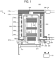
- the process furnace 202 includes a heater 206 as a temperatu re regulator (heating part).
- the heater 206 is formed in a cylindrical shape with open u pper and lower ends, and is installed vertically.
- the heater 206 is composed of five zone heaters 206a, 206b, 206c, 206d and 206e arranged sequentially from the top along an a rrangement direction of wafers 200 as substrates. These heaters 206a to 206e are confi gured such that a temperature of each zone may be controlled individually and independ ently.
- the heater 206 also functions as an activator (exciter) that activates (excites) a ga s with heat.
- An outer wall 210 is provided outside the heater 206.
- the outer wall 210 in cludes a side wall 210a that covers a periphery of the heater 206, a ceiling 210b that cove rs an upper portion of the heater 206, and a bottom 210c that covers a lower portion of t he heater 206.
- An exhaust pipe 254 serving as an exhaust flow path for exhausting a cooling gas (cooling airflow) flowing between the reaction tube 203 and the outer wall 210, is provid ed in the outer wall 210 so as to penetrate the ceiling 210b.
- a blower 270 serving as a c ooling gas exhaust device, is connected to the exhaust pipe 254.
- An exhaust side dampe r or an exhaust side shutter for regulating an exhaust flow rate may be provided on an u pstream side of the blower 270 of the exhaust pipe 254.
- the outer wall 210 is provided with a supply pipe 251 for supplying a cool ing gas between the reaction tube 203 and the outer wall 210.
- a supply side damper 264 is connected to the supply pipe 251 as a cooling gas flow rate regulator for regulating the supply flow rate of the cooling gas.
- a supply side shutter may be connected to the supply pi pe 251.
- the supply side damper 264 is capable of performing supply of the cooling gas a nd stopping the supply between the reaction tube 203 and the outer wall 210 by opening and closing a valve while the blower 270 is in operation.
- the supply side d amper 264 is configured to be capable of adjusting an opening state of the valve while th e blower 270 is operation, so that the flow rate of the cooling gas supplied between the r eaction tube 203 and the outer wall 210 is regulated.
- the flow rate of the cooling gas ma y also be regulated by regulating a rotation speed of the blower 270.
- a cooling gas exhauster is mainly composed of the exhaust pipe 254 and the blow er 270.
- a cooling gas supplier is mainly composed of the supply pipe 251 and the supply side damper 264.
- a process chamber cooler (process chamber cooling system) as a cooli ng device is mainly composed of the cooling gas exhauster and the cooling gas supplier.
- the cooling gas flow rate regulator may include a blower 270 whose rotation speed is co ntrollable, in addition to the supply side damper 264.
- the cooling airflow (cooling gas) t aken in from the supply pipe 251 may be, for example, an air or an inert gas (e.g., a nitro gen gas or a rare gas) supplied from an inert gas supply source (not shown).
- a reaction tube 203 is disposed concentrically with the hea ter 206.
- the reaction tube 203 is made of a heat-resistant material such as quartz (SiO 2 ), silicon carbide (SiC) or the like and is formed in a cylindrical shape with a closed uppe r end and an opened lower end.
- a manifold 209 is disposed below the reaction tube 203 to be concentric with the reaction tube 203.
- the manifold 209 is made of a metal materi al such as stainless steel (SUS) or the like and is formed in a cylindrical shape with open ed upper and lower ends. The upper end of the manifold 209 engages with the bottom 2 10c of the outer wall 210 and is configured to support the bottom 210c.
- a nozzle 249 as a gas introducer is provided in the process chamber 201 so as to p enetrate a side wall of the manifold 209.
- a gas supply pipe (not shown) is connected to t he nozzle 249.
- a processing gas supply source (not shown) or the like is connected to an upstream side of the gas supply pipe, which is a side opposite to a side connected to the nozzle 249, via an MFC (mass flow controller) (not shown), serving as a gas flow rate co ntroller.
- an opening/closing valve e.g., air valve
- the manifold 209 is provided with an exhaust pipe 231 for exhausting an atmosp here in the process chamber 201.
- a vacuum pump 246 as a vacuum exhauster is connec ted to the exhaust pipe 231 via a pressure sensor (not shown) serving as a pressure detec tor for detecting a pressure in the process chamber 201 and an APC valve 244 serving as a pressure regulator.
- the APC valve 244 is configured to perform vacuum-exhaust of th e process chamber 201 and stop the vacuum-exhaust by opening and closing the valve w hile the vacuum pump 246 is in operation.
- a seal cap 219 is provided below the manifold 209 as a furnace port cover capable of airtightly closing a lower end opening of the manifold 209.
- the seal cap 219 is made of a metal material such as stainless steel or the like and is formed in a disk shape.
- the s eal cap 219 is configured to be raised and lowered vertically by a boat elevator 115, which is installed outside the reaction tube 203 and serves as a lift for a boat 217 described late r.
- the boat elevator 115 is configured as a transporter (transport mechanism) that raises and lowers the seal cap 219 to load and unload (transport) the wafers 200 into and out o f the process chamber 201.
- a region in the process container corresponding to the heater 206a (closed end si de of the reaction tube 203) may be referred to as an upper region.
- a region in the proce ss container corresponding to the heater 206b may be included in the upper region.
- a r egion in the process container corresponding to the heater 206e may be referred to as a l ower region.
- a region below the heater 206e in the process container, for example, a reg ion where the manifold 209 and an opening of the reaction tube 203 are located, may be included in the lower region.
- a region in the process container corresponding to the hea ter 206d may be included in the lower region.
- a region in the process container corresponding to the heater 206c may be referred to as a central region.
- a region in the process container corresponding to at least one selected from the group of the heaters 2 06b and 206d may be included in the central region.
- the boat 217 as a substrate transporter is configured to support a plurality of waf ers 200, for example, 25 to 200 wafers, in such a state that the wafers are arranged in a horizontal posture and in multiple stages along a vertical direction with centers of the w afers 200 aligned with one another. That is, the boat 217 is configured to arrange the wa fers 200 to be spaced apart from one another.
- the boat 217 is made of a heat-resistant material such as, for example, quartz, SiC or the like.
- Heat insulating plates 218 made o f a heat-resistant material such as, for example, quartz, SiC or the like are supported in multiple stages at a lower portion of the boat 217.
- a temperature sensor 263 as a tem perature detector. By independently regulating a state of electric power supply to each o f the heaters 206a to 206e included in the heater 206 based on temperature information detected by the temperature sensor 263, a temperature in the process chamber 201 beco mes a desired temperature distribution.
- the temperature sensor 263 is installed along a n inner wall of the reaction tube 203.
- the controller 121 as a control part is configu red as a computer including a CPU (Central Processing Unit) 121a, a RAM (Random Acc ess Memory) 121b, a memory 121c and an I/O port 121d.
- the RAM 121b, the memory 12 1c and the I/O port 121d are configured to be capable of exchanging data with the CPU 1 21a via an internal bus 121e.
- An input/output device 122 configured as, for example, a to uch panel or the like is connected to the controller 121.
- an external memory 123 may be connected to the controller 121.
- the substrate processing apparatus may be configured to include one controller or a plurality of controllers.
- control for perf orming a processing sequence to be described later may be performed using one controll er or a plurality of controllers.
- the plurality of controllers may be configured as a control system by being connected to each other via a wired or wireless communicatio n network, and the control for performing the processing sequence to be described later may be performed by the entire control system.
- controller may include one controller, a plurality of controllers, or a control system configure d by a plurality of controllers.
- the memory 121c is composed of, for example, a flash memory, a HDD (Hard Dis k Drive), a SSD (Solid State Drive), or the like.
- the memory 121c stores, in a readable m anner, control programs for controlling operations of the substrate processing apparatu s, process recipes in which procedures and conditions, etc. of substrate processing to be described later are written, and the like.
- the process recipes are combinations that caus e the controller 121 to have the substrate processing apparatus execute the respective pr ocedures in the below-described substrate processing so as to obtain a predetermined re sult.
- the process recipes function as programs.
- the RAM 121b is configured as a me mory area (work area) in which programs, data, and the like read by the CPU 121a are te mporarily held.
- the I/O port 121d is connected to the MFCs, the valves, the pressure sensor, the APC valve 244, the vacuum pump 246, the heater 206, the temperature sensor 263, the supply side damper 264, the blower 270, the boat elevator 115, and the like.
- the CPU 121a is configured to, according to the contents of the recipe thus read, c ontrol the flow rate regulating operation for various substances (various gases) by the M FCs, the opening/closing operations of the valves, the opening/closing operation of the APC valve 244, the pressure regulating operation by the APC valve 244 based on the pre ssure sensor, the start and stop of the vacuum pump 246, the temperature regulating op eration of the heater 206 based on the temperature sensor 263, the opening/closing con trol for the supply side damper 264, the start, stop and the rotation speed regulation of t he blower 270, the raising and lowering operation of the boat 217 by the boat elevator 11 5, and the like.
- the controller 121 may be configured by installing, in the computer, the above-de scribed programs recorded and stored in the external memory 123.
- the external memor y 123 includes, for example, a magnetic disk such as a HDD or the like, an optical disk su ch as a CD or the like, a magneto-optical disk such as a MO or the like, a semiconductor memory such as a USB memory, a SSD, or the like, and so forth.
- the memory 121c and t he external memory 123 are configured as a computer-readable recording media.
- the memory 121c and the external memory 123 are collectively and simply referre d to as “recording medium.”
- recording medium When the term “recording medium” is used herein, it may refer to a case of including the memory 121c, a case of including the external memory 12 3, or case of including both.
- the provision of the program to the computer may be perfo rmed by using a communication means such as the Internet or a dedicated line without having to use the external memory 123.
- Step A First Temperature Regulating Step
- step A the temperature in the process chamber 201 is regulated to a predeter mined temperature.
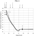
- FIG. 3 shows the t emperature in the process chamber 201 at a predetermined timing for each of the upper region, the central region, and the lower region.
- the vertical axis in FIG. 3 indicates the temperature in each region in the process chamber 201 in [degrees C].
- the horizontal a xis in FIG. 3 indicates an elapsed time in [h].
- the dotted line in FIG. 3 indicates the tem perature at the lower region in the process chamber 201.
- the dashed line indicates the t emperature at the central region in the process chamber 201.
- the solid line indicates th e temperature at the upper region in the process chamber 201.
- the arrow 3 indicates a time when the temperature in the process chamber 201 exhibit s a predetermined distribution (first distribution) due to the temperature regulating in s tep A, and indicates a time when the substrate processing apparatus is in an idle state to be described later.
- the arrow ii indicates a time when the substrate processing apparatu s is in a standby state to be described later.
- the arrow iii indicates a start time of step B to be described later.
- the arrow iv indicates a start time of a pressure regulating step to be described later.
- the arrows v and vi indicate a start time and an end time of a proces s chamber cooling process of step C to be described later.
- the arrow vii indicates a start time of step D to be described later.
- step A while the substrate processing apparatus is in a waiting state (idle state ) until its transitions to the standby state, the temperature in the process chamber 201 is regulated so that the temperature distribution in the arrangement direction of the wafer s 200 in the process chamber 201 becomes the first distribution (see a in FIG. 3 ) in whic h at least a portion (e.g., the lower region) in the process chamber 201 becomes the first temperature (e.g., 100 degrees C). More specifically, set temperatures of the heaters 20 6a to 206e are regulated to achieves the first distribution in which the temperatures in t he upper region, the central region, and the lower region are, for example, 92 degrees C, 96 degrees C, and 100 degrees C (see arrow i in FIG.
- the state of power supply to the heater 206 is feedback-controlled based on the temperature information d etected by the temperature sensor 263 so that the process chamber 201 achieves such a t emperature distribution.
- 100 degrees C which is the temperature in the lo were region
- 92 degrees C which is the temperature in the upper region
- the temperature detected by the temperat ure sensor 263 provided in each region may be used.
- At least one selected from the group of the heaters 206a to 206e maybe turned off while the other heaters are turn ed on to regulate the temperature in the process chamber 201.
- Step B Wafer Loading Step
- the wafers 200 are loaded into the proc ess chamber 201 in a state in which the temperature distribution in the arrangement dir ection of the wafers 200 in the process chamber 201 is in the above-mentioned first dist ribution (see arrow iii in FIG. 3 ).
- the boat 217 which is disposed outside th e substrate processing apparatus and possesses a lower temperature than the temperatu re in the process chamber 201 at a time of loading, is loaded into the substrate processin g apparatus. Therefore, the temperature in the process chamber 201 drops to about 80 degrees C ( see FIG. 3 ).
- Step C Second Temperature Regulating Step
- temper ature regulating in the process chamber 201 is started as a second temperature regulatin g step.
- the set temperatures of the heaters 206a to 206e are regulated so th at the temperature distribution in the arrangement direction of the wafers 200 in the pr ocess chamber 201 becomes the second distribution (target temperature distribution) (s ee b in FIG. 3 ) in which at least a portion (e.g., the lower region) in the process chamber 201 becomes a second temperature (e.g., 60 degrees C), which is a target temperature.
- the set temperatures of the heaters 206a to 206e are regulated so that the te mperatures in the upper region, the central region, and the lower region become 60 degr ees C. That is, in the present embodiments, maximum and minimum values of the temp erature in the second distribution are 60 degrees C, and a second deviation (temperatur e width) of the second distribution is 0 degrees C.
- the set temperat ure of the heater 206 is regulated (changed) in this manner, the temperature in the proc ess chamber 201 does not immediately drop, and the temperature during the standby st ate (approximately 100 degrees C) is essentially maintained for at least a predetermined time until step B is started ( see FIG. 3 ).
- the temperature regulating by the heater 206 as the second temperature regulati ng step is continuously performed even after the start of step B until an end of step D, in accordance with the set temperature of the heater 206 that is regulated to allow the tem perature distribution in the process chamber 201 to achieve the second distribution.
- a s tart timing of the second temperature regulating step is not limited to before the start of step B (the time of transition to the standby state), and may be simultaneous with the st art of step B or any timing between an end of step B and a start of step D.
- the second temperature regulating step further incl udes cooling the process chamber 201 by the process chamber cooler so as to bring the t emperature distribution in the process chamber 201 closer to the second distribution (pr ocess chamber cooling step).
- the cooling gas discharged by the blower 270 i s circulated through a space between the reaction tube 203 and the outer wall 210 (an o uter space of the process chamber 201) via the supply pipe 251 to lower the temperature in the process chamber 201.
- the flow rate of the cooling gas discharged by t he blower 270 is regulated so as to bring the temperature in the process chamber 201 clo ser to the second distribution (see arrows v and vi in FIG. 3 ).
- the flow rate of the coolin g gas is regulated by at least one selected from the group of regulating the opening state of the supply side damper 264 and regulating the rotation speed of the blower 270.
- the cooling gas supplied to between the reaction tube 203 and the outer wall 210 is exhauste d via the exhaust pipe 254.
- step B the vacuum pump 246 performs vacuum-exhaust (deco mpression-exhaust) so that the pressure inside the process chamber 201, i.e., a space in which the wafer 200 exists, reaches a desired pressure (vacuum level) ( see arrow iv in FI G. 3).
- a desired pressure vacuum level
- the pressure inside the process chamber 201 is measured by the pres sure sensor, and the APC valve 244 is feedback-controlled based on the measured press ure information.
- the exhaust of the inside of the process chamber 201 continues at leas t until the processing of the wafers 200 is started.
- Step D Substrate Processing Step
- the wafers 200 loaded into the process chamber 201 are processed.
- predetermined precursor gas, reaction gas, and inert gas are supplied to the wafers 200 in the process chamber 201 to form a desired film on the wafers 200.
- the wafers 200 are processed in a state in w hich the temperature distribution in the arrangement direction of the wafers 200 in the process chamber 201 is set to the second distribution.
- step D an inert gas as a purge gas is supplied into the process chamber 201 from the nozzle and is exhausted through the exhaust pipe 231.
- the inside of the process chamber 201 is purged, and gases, reaction by-products, and t he like remaining in the process chamber 201 are removed from the inside of the proces s chamber 201 (after-purge).
- the atmosphere in the process chamber 201 is replaced with the inert gas (inert gas replacement), and the pressure in the process cha mber 201 is returned to normal pressure (atmospheric pressure recovery).
- the seal cap 219 is lowered by the boat elevator 115, and the lower end of the manifold 209 is opened. Then, the processed wafers 200 are unloaded from the l ower end of the manifold 209 to the outside of the reaction tube 203 while being suppor ted by the boat 217 (boat unloading). After the boat is unloaded, the lower end opening of the manifold 209 is sealed (shutter close). The processed wafers 200 are discharged f rom the boat 217 after they are unloaded to the outside of the reaction tube 203 (wafer d ischarge).
- step A the temperature distribution in the process chamber 201 is regulate d to the first temperature distribution different from the second distribution (target tem perature distribution) used during performing step D, and in step B, the wafers 200 are loaded into the process chamber 201 in the state in which the temperature distribution i s set to the first distribution. Furthermore, in step C, the temperature is regulated to the second temperature distribution, and in step D, the wafers 200 are processed in the stat e in which the temperature distribution is set to the second distribution.
- step B the boat 217 of a low temperature waiting outside the process chamber 201 is loaded into the process chamber 201, so that the temperature in the process chamber 201 drops.
- the boat 217 is raised from an open end sid e of the reaction tube 203 to the closed end side, so that an upper portion of the boat 217 heated by the entire heaters, for example, in the order of the heaters 206e, 206d, 206c, a nd 206b, is disposed in the upper region.
- the lower portion of the boat 217 heated solely by the heater 206e or har dly heated by the heater 206 is disposed in the lower region.
- the portions of the boat 217 that are heated by the heater 206 for different times during the boat loadin g depending on the regions are disposed in the process chamber 201.
- the te mperature in the process chamber 201 after the boat 217 is loaded tends to exhibit devia tions (variations) depending on the regions.
- the temperature is highest in t he upper region, and the temperature decreases downward from the central region to th e lower region.
- step B since the boat loading in step B is performed in the state i n which the lower end opening of the manifold 209 is opened, a low-temperature air out side the substrate processing apparatus flows into the substrate processing apparatus, t hereby lowering the temperature in the process chamber 201.
- the lower region close to the lower end opening of the manifold 209 is most susceptible to the influence of this te mperature drop, and the influence becomes less noticeable upward from the central regi on to the upper region.
- the temperature drop begins immediately af ter the start of boat loading, and then the temperature drop begins in the order of the ce ntral region and the upper region.
- a manner of temperature change ove r time after the start of boat loading diff ers from region to region. Furthermore, the temperature drop is greatest in the lower re gion, and the temperature drop decreases upward from the central region to the upper r egion. This enhances the tendency that the temperature in the process chamber 201 var ies from region to region when step B is performed.
- step B If a large variation in the temperatu re distribution in the process chamber 201 occurs when step B is performed, a time requ ired to eliminate this variation, i.e., a time required for the temperature distribution in t he process chamber 201 to converge to the second distribution (target temperature distr ibution) (convergence time), may become long. This causes a delay in the start of step D , which may reduce the throughput.
- the temperature distrib ution in the process chamber 201 is regulated in step A to the first distribution different from the second distribution that is the target temperature distribution. This makes it p ossible to shorten a time required for the temperature distribution in step C to converge to the second distribution. As a result, the start of step D may be advanced, and a decre ase in the throughput may be avoided.
- step B By making the first temperature of the first distribution in step A higher than the second temperature of the second distribution in step C, it is possible to facilitate the temperature regulating (temperature control) using the heater 206 and shorten the time required to converge to the second distribution (target temperature distribution).
- Furth ermore by maintaining the inside of the process chamber 201 at a high temperature bef ore performing step B in which the wafers 200 are loaded, it is possible to remove moist ure in the process chamber 201 and reduce the influence of moisture in the process cha mber 201 when performing step D.
- step A the heater 206 is controlled so that the first distribution exhibits th e first deviation.
- a predetermined deviation template width
- step A by giving, in advance, a predetermined deviation (tem perature width) to the first distribution in step A, it is possible to reduce the temperatur e deviation (temperature variation from region to region) in the arrangement direction o f the wafers 200 that occurs when the wafers 200 are loaded into the process chamber 2 01.
- step C the temperature in the process chamber 201 is regulated so that the second distribution becomes uniform (the second deviation is zero) in the arrangement direction of the wafers 200.
- the temperature deviation (te mperature variation) in the process chamber 201 that occurs when the wafers 200 are lo aded into the process chamber 201, it is possible to shorten the convergence time when performing the temperature control to obtain the second distribution in which the secon d deviation is zero.
- the first distribution is set such that the time taken for the temperature distrib ution in the process chamber 201 to converge to the second distribution from the start o f step B is shorter compared to a case where the temperature in the process chamber 201 is regulated so that the temperature distribution in the process chamber 201 becomes th e second distribution in step A. This makes it possible to shorten the convergence time and therefore improve the throughput.
- the first distribution is set such that a maximum value of the deviation of the temperature distribution in the process chamber 201 occurring after step B is smaller th an that in the case where the temperature in the process chamber 201 is regulated to all ow the temperature distribution in the process chamber 201 to become the second distri bution in step A. This makes it possible to shorten the convergence time, thereby impro ving the throughput.
- the first distribution is set according to the characteristics of the change in th e temperature distribution in the process chamber 201 caused by the loading of the wafe rs 200 in step B. Specifically, as described above, the lower region (the opening side of t he reaction tube 203) is most susceptible to the influence of the temperature drop in the process chamber 201 caused by the loading of the wafers 200, and the influence is less n oticeable upward, i.e., toward the central region and the upper region (the closed end si de of the reaction tube 203). Taking this characteristic into consideration, in the presen t embodiments, the first distribution is set to possess a deviation that cancels (compensa tes for) the temperature variation that occurs when the wafers 200 are loaded.
- the temperature of the lower region is set to the maximum value in the first distribution
- the temperature of the upper region is set to the minimum value in the first distribu tion ( see FIG. 3 ).
- the temperature of the process chamber 201 is regulated by controlling the he ater 206 that heats the process chamber 201 in step A and controlling the heater 206 an d the blower 270 that cools the process chamber 201 in step C, thus ensuring the above-mentioned effects.
- the substrate processing in the present embodiments may be modified as shown in the following modifications. These modifications may be combined as desired. Unles s otherwise specified, the processing procedure and processing condition in each step of each modification may be the same as the processing procedure and processing conditio n in each step of the substrate processing described above.
- step A it is not necessary to give a deviation (first deviatio n) to the first distribution ( see c in Fig. 4 ) in advance to cancel the temperature deviatio n (temperature variation) that occurs when the wafers 200 are loaded.
- the temperature distributio n in the process chamber 201 may be a first distribution in which the upper region, the c entral region, and the lower region are at the first temperature (e.g., about 100 degrees C) ( see arrow i in FIG. 4 ).
- the entire regions in the process chamber 201 may be heated uniformly so that they are at approximately the same temperature ( see FIG. 4 ).
- FIG. 4 shows the temperature in the process chamber 201 at a predetermined tim ing for each of the upper region, the central region, and the lower region.
- the vertical ax is in FIG. 4 indicates the temperature in each region of the process chamber 201 in [degr ees C].
- the horizontal axis in FIG. 4 indicates the elapsed time in [h].
- the dotted line in FIG. 4 indicates the temperature at the lower region in the process chamber 201.
- the da shed line indicates the temperature at the central region in the process chamber 201.
- Th e solid line indicates the temperature at the upper region in the process chamber 201.
- the arrow 4 indicates the time when the temperature in the pro cess chamber 201 exhibits a predetermined distribution (first distribution) due to the te mperature regulating in step A, and indicates the time when the substrate processing ap paratus is in the idle state.
- the arrow ii indicates the time when the substrate processin g apparatus is in the standby state.
- the arrow iii indicates the start time of step B.
- the arrow iv indicates the start time of the pressure regulating step.
- the arrow vii indicates the start time of step D.
- the temperature in the process chamber 201 may b e regulated to a first distribution ( see e in FIG. 5 ) that is at a same temperature range (a bout 75 degrees C) as the target temperature distribution (second distribution) ( see f in FIG. 5 ).
- the temperature distribution in the process chamber 201 may be a first distribution in whic h the upper region, the central region, and the lower region are at relatively low tempera tures similar to the temperature range (about 75 degrees C) in the substrate processing s tep ( see arrows i and vii in FIG. 5 ).
- the temperature distribution in the process chamber 201 may be a fi rst distribution that is lower than that in the above-described embodiments.
- the minimum value of the temperature in the first distribution may be lower than the maximum value of the temperature in the second distribution ( see FIG. 5 ).
- FIG. 5 shows the temperature in the process chamber 201 at a predetermined tim ing for each of the upper region, the central region, and the lower region.
- the vertical ax is in FIG. 5 indicates the temperature in each region of the process chamber 201 in [degr ees C].
- the horizontal axis in FIG. 5 indicates the elapsed time in [h].
- the dotted line in FIG. 5 indicates the temperature at the lower region in the process chamber 201.
- the da shed line indicates the temperature at the central region in the process chamber 201.
- Th e solid line indicates the temperature at the upper region in the process chamber 201.
- the arrow ii indicates the time when the substrate processin g apparatus is in the standby state.
- the arrow iii indicates the start time of step B.
- the arrow iv indicates the start time of the pressure regulating step.
- the arrow vii indicates the start time of step D.
- a deviation that cancels out the temperature deviatio n (temperature variation) that occurs when the wafers 200 are loaded is given to the firs t distribution in advance in step A, and then the wafers 200 are loaded ( see arrow i in FI G. 5), thereby achieving the effect of shortening the convergence time as compared to a c ase where the wafers 200 are loaded without giving this deviation to the first distributio n.
- the temperatu re in the process chamber 201 is regulated using the heater 206 in step A is described as an example.
- the present disclosure is not limited to such embodiments.
- the temperature in the process chamber 201 may be regulated by simultaneousl y using the heater 206 and the blower 270 during at least a portion of the period of step A.
- the same effects as those of the above-described embodiments may be obtained in th is embodiment.
- a sufficient temperature deviation (ti lt controllable width) may be provided in advance even in a low temperature region.
- the t emperature in the process chamber 201 may be regulated using solely the blower 270 du ring at least a portion of the period of step C. That is, the power supply to the heater 20 6 may be stopped (turned off) during at least a portion of the period of step C.
- the temperature control using the heater 206 may be started or resume d at a timing when a temperature of any region in the process chamber 201 drops to a pr edetermined temperature or lower.
- the same effects as those of the above-described embodiments may be obtained.
- step C the case where the t emperature in the process chamber 201 is regulated so that the second distribution is un iform (the second deviation is zero) in the arrangement direction of the wafers 200 is de scribed as an example.
- the present disclosure is not limited to such embodim ents.
- the second distribution may possess a second deviation that is small er than the first deviation other than zero.
- the same effects as thos e of the above-described embodiments may be obtained.
- step E of increasing the temperature in the process chamber 201 after step D in a state in which the plurality of wafers 200 are accommodated in the process chamber 201, and step F of unloading the wafers 200 from the process chamber 201 after step E may be further perf ormed.
- the same effects as those of the above-described embodime nts may be obtained.
- the wafers 200 may be unloade d from the process chamber 201 after removing moisture generated during the processi ng of step D from the wafers 200 and the process chamber 201.
- a time requ ired for increasing the temperature in the process chamber 201 after unloading the wafe rs 200 may be shortened.
- cooling by the blower 270 is started after the inside of the process chamber 201 is vacuum-exhausted is described as an example.
- the present disclosure is not limited to such embodi ments.
- cooling by the blower 270 may be started before the vacuum-exha ust of the inside of the process chamber 201 is completed.
- the sam e effects as those of the above-described embodiments may be obtained.
- the case where the temperatu re in the process chamber 201 is lowered by allowing the cooling gas taken in through th e supply pipe 251 to circulate in an outer peripheral space of the process chamber 201 an d then be discharged by the blower 270 is described as an example.
- the prese nt disclosure is not limited to such embodiments.
- the flow direction of the cooling gas may be reversed from that of the above-described embodiments.
- the temperature in the process chamber 201 may be lowered by allowing the cooling gas tak en in through the exhaust pipe 254 to circulate in the outer peripheral space of the proce ss chamber 201 and then be discharged by a blower provided on the side of the supply pi pe 251.
- the same effects as those of the above-described embodime nts may be obtained.
- a recipe used for each process is prepared separately accordin g to processing contents and are recorded and stored in the memory 121c via an electric communication line or an external memory 123.
- the CPU 121a suitably selects an appropriate recipe from a plurality of recipes r ecorded and stored in the memory 121c according to the processing contents. This make s it possible to form films of various film types, composition ratios, film qualities and fil m thicknesses with high reproducibility in one substrate processing apparatus. In additi on, the burden on an operator may be reduced, enabling a quick start of each process wh ile avoiding operation errors.
- the above-described recipes are not limited to newly prepared ones, but may be p repared by, for example, changing existing recipes already installed in the substrate proc essing apparatus.
- the recipes after the change may b e installed in the substrate processing apparatus via an electric communication line or a recording medium in which the recipes are recorded.
- the input/output devi ce 122 provided in the existing substrate processing apparatus may be operated to direct ly change the existing recipes already installed in the substrate processing apparatus.
- a fi lm is formed by using a batch type substrate processing apparatus that processes a plura lity of substrates at a time.
- the present disclosure is not limited to the above-described embodiments, but may be suitably applied to, for example, a case where a film is formed using a single-substrate type substrate processing apparatus that processes one or sever al substrates at a time.
- there is desc ribed the example in which a film is formed using a substrate processing apparatus with a hot-wall type process furnace.
- the present disclosure is not limited to the above-desc ribed embodiments, but may also be suitably applied to a case where a film is formed usi ng a substrate processing apparatus with a cold-wall type process furnace.
- each process may be performed under the same processing procedures and processing conditions as those of the above-described embodiments and modifications.
- the same effects as those of the a bove-described embodiments and modifications may be obtained.
- processing procedure and processing conditions at this time may be, for example, the same as the processing procedures and processing conditions of the above-described embodiments and modifications.
Landscapes
- Chemical & Material Sciences (AREA)
- General Chemical & Material Sciences (AREA)
- Chemical Kinetics & Catalysis (AREA)
- Engineering & Computer Science (AREA)
- Materials Engineering (AREA)
- Mechanical Engineering (AREA)
- Metallurgy (AREA)
- Organic Chemistry (AREA)
- Chemical Vapour Deposition (AREA)
- Container, Conveyance, Adherence, Positioning, Of Wafer (AREA)
Applications Claiming Priority (1)
| Application Number | Priority Date | Filing Date | Title |
|---|---|---|---|
| JP2023172049A JP2025062791A (ja) | 2023-10-03 | 2023-10-03 | 基板処理方法、半導体装置の製造方法、プログラム、および基板処理装置 |
Publications (2)
| Publication Number | Publication Date |
|---|---|
| EP4535408A2 true EP4535408A2 (de) | 2025-04-09 |
| EP4535408A3 EP4535408A3 (de) | 2025-05-21 |
Family
ID=92801210
Family Applications (1)
| Application Number | Title | Priority Date | Filing Date |
|---|---|---|---|
| EP24200602.1A Pending EP4535408A3 (de) | 2023-10-03 | 2024-09-16 | Substratverarbeitungsverfahren, verfahren zur herstellung eines halbleiterbauelements, programm und substratverarbeitungsvorrichtung |
Country Status (6)
| Country | Link |
|---|---|
| US (1) | US20250112063A1 (de) |
| EP (1) | EP4535408A3 (de) |
| JP (1) | JP2025062791A (de) |
| KR (1) | KR20250048633A (de) |
| CN (1) | CN119764209A (de) |
| TW (1) | TW202531423A (de) |
Family Cites Families (7)
| Publication number | Priority date | Publication date | Assignee | Title |
|---|---|---|---|---|
| US6951998B2 (en) * | 2000-04-14 | 2005-10-04 | Omron Corporation | Controller, temperature regulator and heat treatment apparatus |
| EP1320124B1 (de) * | 2000-07-25 | 2008-03-12 | Tokyo Electron Limited | Verfahren zur bestimmung von parametern einer thermischen behandlung |
| JP5510991B2 (ja) * | 2007-09-06 | 2014-06-04 | 株式会社日立国際電気 | 半導体製造装置及び基板処理方法 |
| JP5101243B2 (ja) * | 2007-10-29 | 2012-12-19 | 東京エレクトロン株式会社 | 基板処理装置,基板処理装置の制御方法,およびプログラム |
| CN104520975B (zh) * | 2012-07-30 | 2018-07-31 | 株式会社日立国际电气 | 衬底处理装置及半导体器件的制造方法 |
| JP6470060B2 (ja) | 2015-01-30 | 2019-02-13 | 株式会社Kokusai Electric | 半導体装置の製造方法、基板処理装置およびプログラム |
| CN113272940B (zh) * | 2019-01-07 | 2024-03-26 | 株式会社国际电气 | 基板处理装置、半导体装置的制造方法以及加热器单元 |
-
2023
- 2023-10-03 JP JP2023172049A patent/JP2025062791A/ja active Pending
-
2024
- 2024-07-26 TW TW113127716A patent/TW202531423A/zh unknown
- 2024-08-02 CN CN202411063111.7A patent/CN119764209A/zh active Pending
- 2024-09-13 KR KR1020240125304A patent/KR20250048633A/ko active Pending
- 2024-09-16 EP EP24200602.1A patent/EP4535408A3/de active Pending
- 2024-09-17 US US18/887,519 patent/US20250112063A1/en active Pending
Also Published As
| Publication number | Publication date |
|---|---|
| US20250112063A1 (en) | 2025-04-03 |
| CN119764209A (zh) | 2025-04-04 |
| EP4535408A3 (de) | 2025-05-21 |
| KR20250048633A (ko) | 2025-04-10 |
| JP2025062791A (ja) | 2025-04-15 |
| TW202531423A (zh) | 2025-08-01 |
Similar Documents
| Publication | Publication Date | Title |
|---|---|---|
| US12566423B2 (en) | Temperature control method, method of manufacturing semiconductor device, non-transitory computer-readable recording medium and substrate processing apparatus | |
| US12503770B2 (en) | Substrate processing apparatus and non-transitory computer-readable recording medium | |
| US7727780B2 (en) | Substrate processing method and semiconductor manufacturing apparatus | |
| US9099505B2 (en) | Thermal processing apparatus and cooling method | |
| CN109494172B (zh) | 冷却单元、绝热结构体、基板处理装置、以及半导体装置的制造方法 | |
| US11043402B2 (en) | Cooling unit, heat insulating structure, and substrate processing apparatus | |
| JP7362940B2 (ja) | 基板処理装置、温度制御プログラム、半導体装置の製造方法及び温度制御方法 | |
| US20180087709A1 (en) | Substrate processing apparatus and heat insulating pipe structure | |
| US12467689B2 (en) | Furnace opening structure, substrate processing apparatus and method of manufacturing semiconductor device | |
| US12567571B2 (en) | Method of manufacturing semiconductor device | |
| US12387949B2 (en) | Substrate processing apparatus | |
| EP4535408A2 (de) | Substratverarbeitungsverfahren, verfahren zur herstellung eines halbleiterbauelements, programm und substratverarbeitungsvorrichtung | |
| US12085338B2 (en) | Heater, temperature control system, and processing apparatus | |
| US12203169B2 (en) | Substrate processing apparatus, method of processing substrate, method of manufacturing semiconductor device and recording medium | |
| US20250092524A1 (en) | Substrate processing apparatus, control system, and control method | |
| US20250305127A1 (en) | Substrate processing apparatus and method of manufacturing semiconductor device | |
| EP4447095A2 (de) | Verfahren zur substratkühlung, verfahren zur herstellung eines halbleiterbauelements, substratkühlsystem, substratverarbeitungsvorrichtung und programm | |
| US20250291343A1 (en) | Information processing apparatus, substrate processing apparatus, and information processing method | |
| WO2025158707A1 (ja) | 温度制御システム、温度制御方法、半導体装置の製造方法及び基板処理装置 | |
| TW202613756A (zh) | 溫度控制方法、半導體裝置的製造方法、程式、控制器及處理裝置 | |
| WO2026069784A1 (ja) | 温度制御システム、基板加熱方法、半導体装置の製造方法、基板処理装置及び記録媒体 | |
| CN119446960A (zh) | 基片处理方法和基片处理装置 |
Legal Events
| Date | Code | Title | Description |
|---|---|---|---|
| PUAI | Public reference made under article 153(3) epc to a published international application that has entered the european phase |
Free format text: ORIGINAL CODE: 0009012 |
|
| STAA | Information on the status of an ep patent application or granted ep patent |
Free format text: STATUS: REQUEST FOR EXAMINATION WAS MADE |
|
| 17P | Request for examination filed |
Effective date: 20241230 |
|
| AK | Designated contracting states |
Kind code of ref document: A2 Designated state(s): AL AT BE BG CH CY CZ DE DK EE ES FI FR GB GR HR HU IE IS IT LI LT LU LV MC ME MK MT NL NO PL PT RO RS SE SI SK SM TR |
|
| PUAL | Search report despatched |
Free format text: ORIGINAL CODE: 0009013 |
|
| AK | Designated contracting states |
Kind code of ref document: A3 Designated state(s): AL AT BE BG CH CY CZ DE DK EE ES FI FR GB GR HR HU IE IS IT LI LT LU LV MC ME MK MT NL NO PL PT RO RS SE SI SK SM TR |
|
| RIC1 | Information provided on ipc code assigned before grant |
Ipc: H01L 21/67 20060101AFI20250415BHEP |