EP4535017A1 - Apparatus and method for monitoring status of relay circuit - Google Patents
Apparatus and method for monitoring status of relay circuit Download PDFInfo
- Publication number
- EP4535017A1 EP4535017A1 EP24176925.6A EP24176925A EP4535017A1 EP 4535017 A1 EP4535017 A1 EP 4535017A1 EP 24176925 A EP24176925 A EP 24176925A EP 4535017 A1 EP4535017 A1 EP 4535017A1
- Authority
- EP
- European Patent Office
- Prior art keywords
- relay
- current
- microcomputer
- circuits
- output
- Prior art date
- Legal status (The legal status is an assumption and is not a legal conclusion. Google has not performed a legal analysis and makes no representation as to the accuracy of the status listed.)
- Granted
Links
Images


Classifications
-
- H—ELECTRICITY
- H01—ELECTRIC ELEMENTS
- H01H—ELECTRIC SWITCHES; RELAYS; SELECTORS; EMERGENCY PROTECTIVE DEVICES
- H01H47/00—Circuit arrangements not adapted to a particular application of the relay and designed to obtain desired operating characteristics or to provide energising current
- H01H47/002—Monitoring or fail-safe circuits
-
- G—PHYSICS
- G01—MEASURING; TESTING
- G01R—MEASURING ELECTRIC VARIABLES; MEASURING MAGNETIC VARIABLES
- G01R31/00—Arrangements for testing electric properties; Arrangements for locating electric faults; Arrangements for electrical testing characterised by what is being tested not provided for elsewhere
- G01R31/327—Testing of circuit interrupters, switches or circuit-breakers
- G01R31/3271—Testing of circuit interrupters, switches or circuit-breakers of high voltage or medium voltage devices
- G01R31/3275—Fault detection or status indication
-
- G—PHYSICS
- G01—MEASURING; TESTING
- G01R—MEASURING ELECTRIC VARIABLES; MEASURING MAGNETIC VARIABLES
- G01R15/00—Details of measuring arrangements of the types provided for in groups G01R17/00 - G01R29/00, G01R33/00 - G01R33/26 or G01R35/00
- G01R15/14—Adaptations providing voltage or current isolation, e.g. for high-voltage or high-current networks
- G01R15/18—Adaptations providing voltage or current isolation, e.g. for high-voltage or high-current networks using inductive devices, e.g. transformers
-
- G—PHYSICS
- G01—MEASURING; TESTING
- G01R—MEASURING ELECTRIC VARIABLES; MEASURING MAGNETIC VARIABLES
- G01R19/00—Arrangements for measuring currents or voltages or for indicating presence or sign thereof
- G01R19/165—Indicating that current or voltage is either above or below a predetermined value or within or outside a predetermined range of values
- G01R19/16566—Circuits and arrangements for comparing voltage or current with one or several thresholds and for indicating the result not covered by subgroups G01R19/16504, G01R19/16528, G01R19/16533
- G01R19/16571—Circuits and arrangements for comparing voltage or current with one or several thresholds and for indicating the result not covered by subgroups G01R19/16504, G01R19/16528, G01R19/16533 comparing AC or DC current with one threshold, e.g. load current, over-current, surge current or fault current
-
- G—PHYSICS
- G01—MEASURING; TESTING
- G01R—MEASURING ELECTRIC VARIABLES; MEASURING MAGNETIC VARIABLES
- G01R31/00—Arrangements for testing electric properties; Arrangements for locating electric faults; Arrangements for electrical testing characterised by what is being tested not provided for elsewhere
- G01R31/327—Testing of circuit interrupters, switches or circuit-breakers
- G01R31/3271—Testing of circuit interrupters, switches or circuit-breakers of high voltage or medium voltage devices
- G01R31/3272—Apparatus, systems or circuits therefor
- G01R31/3274—Details related to measuring, e.g. sensing, displaying or computing; Measuring of variables related to the contact pieces, e.g. wear, position or resistance
-
- G—PHYSICS
- G01—MEASURING; TESTING
- G01R—MEASURING ELECTRIC VARIABLES; MEASURING MAGNETIC VARIABLES
- G01R31/00—Arrangements for testing electric properties; Arrangements for locating electric faults; Arrangements for electrical testing characterised by what is being tested not provided for elsewhere
- G01R31/327—Testing of circuit interrupters, switches or circuit-breakers
- G01R31/3277—Testing of circuit interrupters, switches or circuit-breakers of low voltage devices, e.g. domestic or industrial devices, such as motor protections, relays, rotation switches
- G01R31/3278—Testing of circuit interrupters, switches or circuit-breakers of low voltage devices, e.g. domestic or industrial devices, such as motor protections, relays, rotation switches of relays, solenoids or reed switches
-
- G—PHYSICS
- G01—MEASURING; TESTING
- G01R—MEASURING ELECTRIC VARIABLES; MEASURING MAGNETIC VARIABLES
- G01R31/00—Arrangements for testing electric properties; Arrangements for locating electric faults; Arrangements for electrical testing characterised by what is being tested not provided for elsewhere
- G01R31/36—Arrangements for testing, measuring or monitoring the electrical condition of accumulators or electric batteries, e.g. capacity or state of charge [SoC]
- G01R31/396—Acquisition or processing of data for testing or for monitoring individual cells or groups of cells within a battery
-
- H—ELECTRICITY
- H01—ELECTRIC ELEMENTS
- H01H—ELECTRIC SWITCHES; RELAYS; SELECTORS; EMERGENCY PROTECTIVE DEVICES
- H01H47/00—Circuit arrangements not adapted to a particular application of the relay and designed to obtain desired operating characteristics or to provide energising current
- H01H47/22—Circuit arrangements not adapted to a particular application of the relay and designed to obtain desired operating characteristics or to provide energising current for supplying energising current for relay coil
- H01H47/32—Energising current supplied by semiconductor device
-
- H—ELECTRICITY
- H01—ELECTRIC ELEMENTS
- H01H—ELECTRIC SWITCHES; RELAYS; SELECTORS; EMERGENCY PROTECTIVE DEVICES
- H01H50/00—Details of electromagnetic relays
- H01H50/44—Magnetic coils or windings
- H01H50/443—Connections to coils
Definitions
- the present invention relates to an apparatus and method for monitoring a status of a relay circuit.
- a microcomputer (or processor) of the container BMS supplies power of a specified voltage level (e.g., 24 V) to each of a plurality of RBMS through a relay circuit.
- a specified voltage level e.g., 24 V
- a plurality of relay circuits e.g., Relay Circuit #1 to Relay Circuit #N
- Relay Circuit #1 to Relay Circuit #N are implemented in parallel so as to correspond to the plurality of RBMSs, respectively.
- the plurality of relay circuits are implemented such that the power is supplied to a first RBMS through a first relay circuit to drive the first RBMS, the power is supplied to a second RBMS through a second relay circuit to drive the second RBMS, and the power is supplied to an Nth RBMS through an Nth relay circuit to drive the Nth RBMS.
- the microcomputer (or processor) of the container BMS outputs relay control signals Relay _sig1 to Relay_sigN (e.g., relay on signals or relay-off signals) to the relay circuits (e.g., Relay Circuit #1 to Relay Circuit #N) corresponding to the RBMSs to be driven, and as the relay control signals Relay _sig1 to Relay_sigN are applied, power of a specified voltage level (e.g., 24 V) is applied to coils of the corresponding relays, thereby driving the corresponding relays.
- a specified voltage level e.g., 24 V
- the same level of voltage e.g., 24 V
- the same level of voltage e.g., 24 V
- the present invention is also directed to providing an apparatus and method for monitoring a status of a relay circuit, enabling a circuit configuration for monitoring operation statuses of a plurality of relay circuits connected in parallel to be simplified.
- the current application/detection circuit may include a current detection resistor for detecting a current applied to each relay coil from a power source and a comparator configured to detect and output a voltage across both ends of the current detection resistor.
- the microcomputer When the microcomputer outputs the relay control signals to the plurality of relay circuits in order to compare the current detected and the current calculated, the microcomputer calculates a voltage level converted from the current flowing corresponding to the number of relay circuits, to which the relay control signals have been output up to the current point, detects the current flowing through the current application/detection circuit, and converts the current detected to a voltage level.
- the microcomputer determines that the relay circuit, which is currently receiving the relay control signal and driven, is normal.
- the microcomputer may determine that the relay circuit, which is currently receiving the relay control signal and driven, is normal.
- first, second, third, etc. may be used herein to describe various elements, components, regions, layers, and/or sections, these elements, components, regions, layers, and/or sections should not be limited by these terms. These terms are used to distinguish one element, component, region, layer, or section from another element, component, region, layer, or section. Thus, a first element, component, region, layer, or section discussed below could be termed a second element, component, region, layer, or section without departing from the teachings of example embodiments.
- spatially relative terms such as “beneath,” “below,” “lower,” “above,” “upper,” and the like, may be used herein for ease of description to describe one element or feature's relationship to another element(s) or feature(s) as illustrated in the figures. It will be understood that the spatially relative terms are intended to encompass different orientations of the device in use or operation in addition to the orientation depicted in the figures. For example, if the device in the figures is turned over, elements described as “below” or “beneath” other elements or features would then be oriented “above” or “over” the other elements or features. Thus, the term “below” may encompass both an orientation of above and below. The device may be otherwise oriented (rotated 90 degrees or at other orientations), and the spatially relative descriptors used herein should be interpreted accordingly.
- An apparatus for monitoring a status of a relay circuit can be implemented in a container battery management system (BMS).
- BMS container battery management system
- the plurality of relay circuits e.g., Relay Circuit #1 to Relay Circuit #15 are connected in parallel and each is applied with driving power of the same voltage level.
- the current application/detection circuit 110 includes a current detection resistor Rc for detecting a current applied to each relay coil from a power source (Source), and a comparator (Comp) that detects and outputs a voltage across both ends of the current detection resistor Rc.
- the current applied to the plurality of relay circuits e.g., Relay Circuit #1 to Relay Circuit #15 from the power source (Source) of the current application/detection circuit 110 constantly increases or decreases in proportion to the number of relay circuits currently being driven.
- a level of the voltage across both ends of the current detection resistor RC detected through the comparator (Comp) also increases or decreases accordingly at a constant rate.
- the microcomputer (or processor) 120 compares the detected current output level (i.e., the level of voltage converted from the current) and the calculated current output level (i.e., the level of voltage converted from the current) while turning on/off any of the relay circuits and checks whether the levels are equal to each other within the specified error range, so that operation statuses of the plurality of relay circuits can be rapidly monitored, and a circuit configuration for monitoring the operation statuses of the plurality of relay circuits connected in parallel can be simplified.
- the detected current output level i.e., the level of voltage converted from the current
- the calculated current output level i.e., the level of voltage converted from the current
- the current output level (i.e., the level of voltage converted from the current) is output through the current application/detection circuit 110 (see FIG. 2 , line (b)).
- the current output level i.e., the level of voltage converted from the current
- the current application/detection circuit 110 see FIG. 2 , line (b)
- the current application/detection circuit 110 Since a current proportional to the number of relay circuits currently driven flows through the current detection resistor Rc of the current application/detection circuit 110, the current application/detection circuit 110 outputs a current output level (i.e., the level of voltage converted from the current) proportional to the number of relay circuits currently driven.
- a current output level i.e., the level of voltage converted from the current
- a first relay control signal Relay_sig1 e.g., a relay-on signal
- a first relay circuit e.g., Relay Circuit #1
- a current output level Current_OUT i.e., the level of voltage converted from the current
- a certain unit i.e., by an amount corresponding to the current flowing as one relay circuit is turned on
- the second relay control signal Relay _sig2 (e.g., a relay-off signal) is output by the microcomputer 120 to turn off the second relay circuit (e.g., Relay Circuit #2) as shown in FIG. 3 , line (c)
- the current output level Current_OUT i.e., the level of voltage converted from the current
- the certain unit i.e., by an amount corresponding to the current flowing as one relay circuit is turned on
- FIG. 4 is a flowchart for describing a method of monitoring a status of the relay circuit according to one or more embodiments of the present invention.
- a current output level i.e., a level of voltage converted from the current
- the current output level i.e., the level of voltage converted from the current
Landscapes
- Physics & Mathematics (AREA)
- General Physics & Mathematics (AREA)
- Engineering & Computer Science (AREA)
- Power Engineering (AREA)
- Theoretical Computer Science (AREA)
- Measurement Of Current Or Voltage (AREA)
- Power Sources (AREA)
- Electromagnetism (AREA)
Abstract
Description
- The present invention relates to an apparatus and method for monitoring a status of a relay circuit.
- In general, an energy storage system (ESS) controls an operation sequence of rack battery management systems (RBMSs) in a container BMS.
- To this end, a microcomputer (or processor) of the container BMS supplies power of a specified voltage level (e.g., 24 V) to each of a plurality of RBMS through a relay circuit.
- In this case, a plurality of relay circuits (e.g.,
Relay Circuit # 1 to Relay Circuit #N) are implemented in parallel so as to correspond to the plurality of RBMSs, respectively. - For example, the plurality of relay circuits are implemented such that the power is supplied to a first RBMS through a first relay circuit to drive the first RBMS, the power is supplied to a second RBMS through a second relay circuit to drive the second RBMS, and the power is supplied to an Nth RBMS through an Nth relay circuit to drive the Nth RBMS.
- Accordingly, the microcomputer (or processor) of the container BMS outputs relay control signals Relay _sig1 to Relay_sigN (e.g., relay on signals or relay-off signals) to the relay circuits (e.g.,
Relay Circuit # 1 to Relay Circuit #N) corresponding to the RBMSs to be driven, and as the relay control signals Relay _sig1 to Relay_sigN are applied, power of a specified voltage level (e.g., 24 V) is applied to coils of the corresponding relays, thereby driving the corresponding relays. - At this time, in the relay circuits (e.g., each of
Relay Circuit # 1 to Relay Circuit #N), the same level of voltage (e.g., 24 V) is applied to the coil of each relay. - Thus, it is necessary to check an operation status of each relay (i.e., whether the relay is failed or not) because the container BMS uses a plurality of relays.
- To this end, conventionally, in order to check the operation status of each relay (or the relay circuit) (i.e., whether the relay is failed or not), a method of comparing a voltage level (e.g., 24 V) of power input to operate each relay and a voltage level of output power and determining that a failure has occurred when the voltage level of the input power and the voltage level of the output power are different was used.
- Accordingly, in order to check the operation statuses of the plurality of relays (or relay circuits) by using the conventional method, the number of ports (or terminals) corresponding to the number of relays must be provided in the microcomputer (or processor), which complicates a circuit configuration and increases costs.
- The related art of the present invention is disclosed in
Korean Patent Publication No. 10-2023-0067793 (published on May 17, 2023 - The above information disclosed in this Background section is for enhancement of understanding of the background of the present disclosure, and therefore, it may contain information that does not constitute related (or prior) art.
- The present invention is directed to providing an apparatus and method for monitoring a status of a relay circuit, enabling operation statuses of a plurality of relay circuits connected in parallel to be rapidly monitored.
- The present invention is also directed to providing an apparatus and method for monitoring a status of a relay circuit, enabling a circuit configuration for monitoring operation statuses of a plurality of relay circuits connected in parallel to be simplified.
- According to an aspect of the present invention, there is provided an apparatus for monitoring a status of a relay circuit including a plurality of relay circuits configured to apply driving power to a plurality of battery management devices, respectively, a microcomputer configured to output relay control signals for respectively turning on/off the plurality of relay circuits, and a current application/detection circuit configured to apply a current to each of the plurality of relay circuits that are turned on by the relay control signals output from the microcomputer, and to detect and convert a total current applied to the plurality of relay circuits turned on, to a voltage level, wherein the microcomputer makes a comparison between a current detected through the current application/detection circuit while selectively turning on/off the plurality of relay circuits and a current calculated corresponding to a number of relay circuits of the plurality of relay circuits to which relay-on signals have been output up to a current point, and determines an operation status of the plurality of relay circuits according to whether the current detected and the current calculated are equal to each other within a specified error range.
- The plurality of relay circuits may be implemented as circuits of a same type, may be connected in parallel, and may each be applied with driving power of a same voltage level.
- Each of the plurality of relay circuits may include a switching element switched by a relay control signal and a relay switched by applying power to a relay coil in response to switching of the switching element.
- The switching element insulates a port of the microcomputer from the relay, and includes a photo coupler.
- The plurality of battery management devices may include a rack battery management system.
- The current application/detection circuit may include a current detection resistor for detecting a current applied to each relay coil from a power source and a comparator configured to detect and output a voltage across both ends of the current detection resistor.
- The current application/detection circuit may detect a voltage proportional to a current flowing through the current detection resistor and may output the voltage to the microcomputer as a current proportional to a number of relay circuits currently turned on and driven flows through the current detection resistor.
- When the microcomputer outputs the relay control signals to the plurality of relay circuits in order to compare the current detected and the current calculated, the microcomputer calculates a voltage level converted from the current flowing corresponding to the number of relay circuits, to which the relay control signals have been output up to the current point, detects the current flowing through the current application/detection circuit, and converts the current detected to a voltage level.
- When the detected current and the calculated current are equal within the specified error range as a result of the comparison, the microcomputer determines that the relay circuit, which is currently receiving the relay control signal and driven, is normal.
- When the detected current and the calculated current are not equal within the specified error range as a result of the comparison, the microcomputer determines that the relay circuit, which is currently receiving the relay control signal and driven, is abnormal.
- According to another aspect of the present invention, there is provided a method of monitoring a status of a relay circuit, including selectively turning on/off a plurality of relay circuits that respectively apply driving power to a plurality of battery management device, by a microcomputer of an apparatus for monitoring the status of the relay circuit, comparing a current detected through a current application/detection circuit with a current calculated corresponding to a number of relay circuits to which relay-on signals have been output up to the current point, by the microcomputer, and determining, by the microcomputer, based on a result of the comparing, an operation status of the relay circuit, wherein the current application/detection circuit applies a current to each of the plurality of relay circuits that are turned on by the output relay control signals from the microcomputer, and detects and converts a total current applied to the relay circuits turned on, to a voltage level.
- The current application/detection circuit may detect a voltage proportional to a current flowing through a current detection resistor and may output the voltage to the microcomputer as a current proportional to the number of relay circuits currently turned on and driven flows through the current detection resistor.
- When the microcomputer outputs the relay control signals to the plurality of relay circuits in order to perform the comparing, the microcomputer may calculate a voltage level converted from the current flowing corresponding to the number of relay circuits, to which the relay control signals have been output up to the current point, may detect the current flowing through the current application/detection circuit, and may convert the current to a voltage level.
- When the currents are equal to each other within the specified error range as a result of comparing the current detected through the current application/detection circuit with the current calculated corresponding to the number of relay circuits to which the relay-on signals have been output up to the current point, the microcomputer may determine that the relay circuit, which is currently receiving the relay control signal and driven, is normal.
- When the currents are not equal to each other within the specified error range as a result of comparing the current detected and the current calculated, the microcomputer may determine that the relay circuit, which is currently receiving a relay control signal and is being driven, is abnormal.
- At least some of the above and other features of the invention are set out in the claims.
- The above and other objects, features and advantages of the present invention will become more apparent to those of ordinary skill in the art by describing example embodiments thereof in detail with reference to the accompanying drawings, in which:
-
FIG. 1 is an example diagram illustrating a schematic configuration of an apparatus for monitoring a status of a relay circuit according to one or more embodiments of the present disclosure; -
FIG. 2 is an example diagram for describing a process of turning on/off the relay circuit by a microcomputer inFIG. 1 ; -
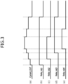
FIG. 3 is an example diagram for describing an increase or decrease in a current output level output from a current application/detection circuit according to the turning on/off of the relay circuit inFIG. 1 ; and -
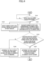
FIG. 4 is a flowchart for describing a method of monitoring a status of the relay circuit according to one embodiment of the present invention. - Hereinafter, one embodiment according to the present invention will be described with reference to the accompanying drawings.
- In this process, the thicknesses of lines or the sizes of elements illustrated in the drawings may be exaggerated for clarity and convenience of description. In addition, the terms described below are defined in consideration of functions of the present invention, which may vary depending on the intention of a user or operator, or custom. Thus, the definitions of the terms should be based on contents throughout this specification.
- The embodiments described in this specification and the configurations shown in the drawings are only some of the embodiments of the present disclosure and do not represent all of the technical ideas, aspects, and features of the present disclosure. Accordingly, it should be understood that there may be various equivalents and modifications that can replace or modify the embodiments described herein at the time of filing this application.
- It will be understood that when an element or layer is referred to as being "on," "connected to," or "coupled to" another element or layer, it may be directly on, connected, or coupled to the other element or layer or one or more intervening elements or layers may also be present. When an element or layer is referred to as being "directly on," "directly connected to," or "directly coupled to" another element or layer, there are no intervening elements or layers present. For example, when a first element is described as being "coupled" or "connected" to a second element, the first element may be directly coupled or connected to the second element or the first element may be indirectly coupled or connected to the second element via one or more intervening elements.
- In the figures, dimensions of the various elements, layers, etc. may be exaggerated for clarity of illustration. The same reference numerals designate the same elements. As used herein, the term "and/or" includes any and all combinations of one or more of the associated listed items. Further, the use of "may" when describing embodiments of the present disclosure relates to "one or more embodiments of the present disclosure." Expressions, such as "at least one of' and "any one of," when preceding a list of elements, modify the entire list of elements and do not modify the individual elements of the list. When phrases such as "at least one of A, B and C, "at least one of A, B or C," "at least one selected from a group of A, B and C," or "at least one selected from among A, B and C" are used to designate a list of elements A, B and C, the phrase may refer to any and all suitable combinations or a subset of A, B and C, such as A, B, C, A and B, A and C, B and C, or A and B and C. As used herein, the terms "use," "using," and "used" may be considered synonymous with the terms "utilize," "utilizing," and "utilized," respectively. As used herein, the terms "substantially," "about," and similar terms are used as terms of approximation and not as terms of degree, and are intended to account for the inherent variations in measured or calculated values that would be recognized by those of ordinary skill in the art.
- It will be understood that, although the terms first, second, third, etc. may be used herein to describe various elements, components, regions, layers, and/or sections, these elements, components, regions, layers, and/or sections should not be limited by these terms. These terms are used to distinguish one element, component, region, layer, or section from another element, component, region, layer, or section. Thus, a first element, component, region, layer, or section discussed below could be termed a second element, component, region, layer, or section without departing from the teachings of example embodiments.
- Spatially relative terms, such as "beneath," "below," "lower," "above," "upper," and the like, may be used herein for ease of description to describe one element or feature's relationship to another element(s) or feature(s) as illustrated in the figures. It will be understood that the spatially relative terms are intended to encompass different orientations of the device in use or operation in addition to the orientation depicted in the figures. For example, if the device in the figures is turned over, elements described as "below" or "beneath" other elements or features would then be oriented "above" or "over" the other elements or features. Thus, the term "below" may encompass both an orientation of above and below. The device may be otherwise oriented (rotated 90 degrees or at other orientations), and the spatially relative descriptors used herein should be interpreted accordingly.
- The terminology used herein is for the purpose of describing embodiments of the present disclosure and is not intended to be limiting of the present disclosure. As used herein, the singular forms "a" and "an" are intended to include the plural forms as well, unless the context clearly indicates otherwise. It will be further understood that the terms "includes," "including," "comprises," and/or "comprising," when used in this specification, specify the presence of stated features, integers, steps, operations, elements, and/or components but do not preclude the presence or addition of one or more other features, integers, steps, operations, elements, components, and/or groups thereof.
- Also, any numerical range disclosed and/or recited herein is intended to include all subranges of the same numerical precision subsumed within the recited range. For example, a range of "1.0 to 10.0" is intended to include all subranges between (and including) the recited minimum value of 1.0 and the recited maximum value of 10.0, that is, having a minimum value equal to or greater than 1.0 and a maximum value equal to or less than 10.0, such as, for example, 2.4 to 7.6. Any maximum numerical limitation recited herein is intended to include all lower numerical limitations subsumed therein, and any minimum numerical limitation recited in this specification is intended to include all higher numerical limitations subsumed therein. Accordingly, Applicant reserves the right to amend this specification, including the claims, to expressly recite any sub-range subsumed within the ranges expressly recited herein. All such ranges are intended to be inherently described in this specification.
- References to two compared elements, features, etc. as being "the same" may mean that they are "substantially the same". Thus, the phrase "substantially the same" may include a case having a deviation that is considered low in the art, for example, a deviation of 5% or less. In addition, when a certain parameter is referred to as being uniform in a given region, it may mean that it is uniform in terms of an average.
- Throughout the specification, unless otherwise stated, each element may be singular or plural.
- When an arbitrary element is referred to as being disposed (or located or positioned) on the "above (or below)" or "on (or under)" a component, it may mean that the arbitrary element is placed in contact with the upper (or lower) surface of the component and may also mean that another component may be interposed between the component and any arbitrary element disposed (or located or positioned) on (or under) the component.
- In addition, it will be understood that when an element is referred to as being "coupled," "linked" or "connected" to another element, the elements may be directly "coupled," "linked" or "connected" to each other, or an intervening element may be present therebetween, through which the element may be "coupled," "linked" or "connected" to another element. In addition, when a part is referred to as being "electrically coupled" to another part, the part can be directly connected to another part or an intervening part may be present therebetween such that the part and another part are indirectly connected to each other.
- Throughout the specification, when "A and/or B" is stated, it means A, B or A and B, unless otherwise stated. That is, "and/or" includes any or all combinations of a plurality of items enumerated. When "C to D" is stated, it means C or more and D or less, unless otherwise specified.
- An apparatus for monitoring a status of a relay circuit according to one or more embodiments can be implemented in a container battery management system (BMS).
-
FIG. 1 is an example diagram illustrating a schematic configuration of an apparatus for monitoring a status of a relay circuit according to one embodiment of the present invention. - As shown in
FIG. 1 , the apparatus for monitoring a status of a relay circuit according to the present embodiment includes a plurality of relay circuits (e.g.,Relay Circuit # 1 to Relay Circuit #15) configured to apply driving power of a specified voltage level (e.g., 24 V) to each of a plurality of rack BMSs (RBMSs), a microcomputer (or processor) 120 configured to output relay control signals Relay_sig1 to Relay_sig15 (e.g., relay-on signals or relay-off signals) to the relay circuits (e.g.,Relay Circuit # 1 to Relay Circuit #15) corresponding to the respective RBMS in order to apply or block the driving power to the corresponding RBMS, and a current application/detection circuit 110 configured to apply a current to each of one or more relay circuits (e.g.,Relay Circuit # 1 to Relay Circuit #15) driven by the relay control signals (Relay_sig1 to Relay_sig15), and detect a level (i.e., a level of voltage converted from the current) of the total current applied to the one or more relay circuits. - In this case, the plurality of relay circuits (e.g.,
Relay Circuit # 1 to Relay Circuit #15) are connected in parallel and each is applied with driving power of the same voltage level. - The plurality of relay circuits (e.g.,
Relay Circuit # 1 to Relay Circuit #15) are implemented as circuits of the same type. - For example, each of the relay circuits (e.g.,
Relay Circuit # 1 to Relay Circuit #15) includes a switching element (e.g., a photo coupler) that is switched in response to one of the relay control signals (Relay_sig1 to Relay _sig15), and a relay that is switched by applying power to a relay coil in response to the switching of the switching element (e.g., a photo coupler). At this time, a port (or terminal) of the microcomputer (or processor) 120 and the relay are insulated from each other through the switching element (e.g., a photo coupler). - The current application/
detection circuit 110 includes a current detection resistor Rc for detecting a current applied to each relay coil from a power source (Source), and a comparator (Comp) that detects and outputs a voltage across both ends of the current detection resistor Rc. - For example, since the plurality of relay circuits (e.g.,
Relay Circuit # 1 to Relay Circuit #15) are connected in parallel, the current applied to the plurality of relay circuits (e.g.,Relay Circuit # 1 to Relay Circuit #15) from the power source (Source) of the current application/detection circuit 110 constantly increases or decreases in proportion to the number of relay circuits currently being driven. Thus, as the current applied to the plurality of relay circuits from the power source (Source) increases or decreases, a level of the voltage across both ends of the current detection resistor RC detected through the comparator (Comp) also increases or decreases accordingly at a constant rate. - When the microcomputer (or processor) 120 outputs the relay control signals Relay_sig1 to Relay_sig15 (e.g., relay-on signals or relay-off signals) to the plurality of relay circuits (e.g.,
Relay Circuit # 1 to Relay Circuit #15), the microcomputer (or processor) 120 calculates a current output level (i.e., a level of voltage converted from the current) corresponding to the number of relay circuits to which the relay-on signals have been output up to the current point (i.e., a current point in time), and also detects a current output level (i.e., a level of voltage converted from the current) actually applied to the plurality of relay circuits through the current application/detection circuit 110. - Further, the microcomputer (or processor) 120 compares the detected current output level (i.e., the level of voltage converted from the current) and the calculated current output level (i.e., the level of voltage converted from the current) to check whether the levels are equal to each other within a specified error range.
- Further, the microcomputer (or processor) 120 compares the detected current output level (i.e., the level of voltage converted from the current) and the calculated current output level (i.e., the level of voltage converted from the current), and determines that the relay circuit (or relay), to which the relay control signal (e.g., a relay-on signal or a relay-off signal) is currently output, is normal when the currents are equal to each other within the specified error range.
- Further, the microcomputer (or processor) 120 compares the detected current output level (i.e., the level of voltage converted from the current) and the calculated current output level (i.e., the level of voltage converted from the current), and determines that the relay circuit (or relay), to which the relay control signal (e.g., a relay-on signal or a relay-off signal) is currently output, is abnormal when the currents are not equal to each other within the specified error range.
- Accordingly, the microcomputer (or processor) 120 compares the detected current output level (i.e., the level of voltage converted from the current) and the calculated current output level (i.e., the level of voltage converted from the current) while turning on/off any of the relay circuits and checks whether the levels are equal to each other within the specified error range, so that operation statuses of the plurality of relay circuits can be rapidly monitored, and a circuit configuration for monitoring the operation statuses of the plurality of relay circuits connected in parallel can be simplified.
-
FIG. 2 is an example diagram for describing a process of turning on/off the relay circuit by the microcomputer inFIG. 1 . However, it should be noted thatFIG. 2 is somewhat exaggerated to facilitate understanding of the on/off operation of the relay circuit by the microcomputer. - Referring to
FIG. 2 , when the microcomputer (or processor) 120 applies power 24V_Coil of a specified voltage level to a relay coil through the current application/detection circuit 110 to turn on the relay circuit (seeFIG. 2 , line (a)), and applies the relay control signal (i.e., a relay-on signal) to the relay circuit to be driven (seeFIG. 2 , line (c)) a transistor Q1 connected to the photo coupler of the current application/detection circuit 110 is turned on (seeFIG. 2 , line (d)), the photo coupler is turned on (seeFIG. 2 , line (e)) as the transistor Q1 is turned on, the relay is turned on (seeFIG. 2 , line (f)) as the photo coupler is turned on, and driving power 24V_Rly is output as the relay is turned on. - Accordingly, the current output level (i.e., the level of voltage converted from the current) is output through the current application/detection circuit 110 (see
FIG. 2 , line (b)). - Referring to
FIG. 2 again, if the microcomputer (or processor) 120 applies the relay control signal (i.e., a relay-off signal) to the relay circuit to be turned off (seeFIG. 2 , line (c)) in the state, in which the power 24V_Coil of a specified voltage level is applied to the relay coil through the current application/detection circuit 110, to turn off the relay circuit (seeFIG. 2 , line (a)), the transistor Q1 connected to the photo coupler of the current application/detection circuit 110 is turned off (seeFIG. 2 , line (d)), the photo coupler is turned off (seeFIG. 2 , line (e)) as the transistor Q1 is turned off, the relay is turned off (seeFIG. 2 , line (f)) as the photo coupler is turned off, and the outputting of the driving power 24V_Rly is stopped as the relay is turned off. - Accordingly, the current output level (i.e., the level of voltage converted from the current) being output from the current application/detection circuit 110 (see
FIG. 2 , line (b)) is not output. -
FIG. 3 is an example diagram for describing an increase or decrease in a current output level (i.e., the level of voltage converted from the current) output from the current application/detection circuit 110 according to the turning on/off of the relay circuit inFIG. 1 . However, it is noted thatFIG. 3 is somewhat exaggerated to facilitate understanding of the operation in which the current output level increases or decreases depending on the on/off operation of the relay circuit. - Referring to
FIG. 3 , in the current application/detection circuit 110, the driving power 24V_Coil from the power source Source is initially applied to the relay circuits, but when the relay control signals Relay_sig1 to Relay_sig15 are not output from themicrocomputer 120 to the relay circuits (e.g.,Relay Circuit # 1 to Relay Circuit #15) to be driven, the voltage is not detected at both ends of the current detection resistor Rc (in other words, the current output level (i.e., the level of voltage converted from the current) is not output from the current application/detection circuit 110) because the power is not applied to the relay circuit (i.e., because no current flows through the relay circuit). - At this time, when the relay control signals (Relay_sig1 to Relay_sig15) are output from the
microcomputer 120 to the relay circuits (e.g.,Relay Circuit # 1 to Relay Circuit #15) to be driven, the voltage across both ends of the current detection resistor Rc is detected (in other words, the current output level (i.e., the level of voltage converted from the current) is output from the current application/detection circuit 110) because the power is applied to the relay circuit (i.e., because current flows through the relay circuit). - Since a current proportional to the number of relay circuits currently driven flows through the current detection resistor Rc of the current application/
detection circuit 110, the current application/detection circuit 110 outputs a current output level (i.e., the level of voltage converted from the current) proportional to the number of relay circuits currently driven. - For example, when a first relay control signal Relay_sig1 (e.g., a relay-on signal) is output by the
microcomputer 120 to turn on the first relay circuit (e.g., Relay Circuit #1) as shown inFIG. 3 , line (b), a current output level Current_OUT (i.e., the level of voltage converted from the current) output by the current application/detection circuit 110 increases by a certain unit (i.e., by an amount corresponding to the current flowing as one relay circuit is turned on) as shown inFIG. 3 , line (a). Similarly, as shown inFIG. 3 , lines (c), (d) and (e) it can be seen that whenever themicrocomputer 120 sequentially outputs second, third, and fourth relay control signals (e.g., Relay _sig2 to Relay _sig4) to turn on second, third, and fourth relay circuits (e.g.,Relay Circuit # 2 to Relay Circuit #4), the current output level Current_OUT (i.e., the level of voltage converted from the current) output from the current application/detection circuit 110 increases in sequence by the certain unit (i.e., by an amount corresponding to the current flowing as one relay circuit is turned on) as shown inFIG. 3 , line(a). - Meanwhile, when the second relay control signal Relay _sig2 (e.g., a relay-off signal) is output by the
microcomputer 120 to turn off the second relay circuit (e.g., Relay Circuit #2) as shown inFIG. 3 , line (c), the current output level Current_OUT (i.e., the level of voltage converted from the current) output by the current application/detection circuit 110 decreases by the certain unit (i.e., by an amount corresponding to the current flowing as one relay circuit is turned on) as shown inFIG. 3 , line (a). Similarly, as shown inFIG. 3 , lines (e), (b) and (d), it can be seen that whenever themicrocomputer 120 sequentially outputs the fourth, first, and third relay control signals (e.g., Relay_sig4, Relay_sig1, and Relay_sig3) to turn off the fourth, first, and third relay circuits (e.g.,Relay Circuit # 4,Relay Circuit # 1, and Relay Circuit #3), the current output level Current_OUT (i.e., the level of voltage converted from the current) output from the current application/detection circuit 110 decreases in sequence by the certain unit (i.e., by an amount corresponding to the current flowing as one relay circuit is turned on) as shown inFIG. 3 , line (a). -
FIG. 4 is a flowchart for describing a method of monitoring a status of the relay circuit according to one or more embodiments of the present invention. - Referring to
FIG. 4 , when themicrocomputer 120 outputs relay control signals Relay_sig1 to Relay_sig15 (e.g., relay-on signals or relay-off signals) to the plurality of relay circuits (e.g.,Relay Circuit # 1 to Relay Circuit #15) (YES in S101), themicrocomputer 120 calculates (S102) a current output level (i.e., a level of voltage converted from the current) corresponding to the number of relay circuits to which the relay-on signals have been output up to the current point.(i.e., a current point in time). - Further, a current output level (i.e., a level of voltage converted from the current) that is actually applied to the plurality of relay circuits is detected (S103) through the current application/
detection circuit 110. That is, the current output level (i.e., the level of voltage converted from the current) output from the current application/detection circuit 110 is detected. - Further, the
microcomputer 120 compares the current output level (i.e., the level of voltage converted from the current) detected through the current application/detection circuit 110 with the current output level (i.e., the level of voltage converted from the current) calculated corresponding to the number of relay circuits to which the relay-on signals have been output up to the current point, and checks (S104) whether the levels are equal to each other within a specified error range. - Further, the
microcomputer 120 compares the current output level (i.e., the level of voltage converted from the current) detected through the current application/detection circuit 110 with the current output level (i.e., the level of voltage converted from the current) calculated corresponding to the number of relay circuits to which the relay-on signals have been output up to the current point, and determines (S 105) that the relay circuit to which the relay control signal (e.g., the relay-on signal or the relay-off signal) is currently output is normal when the currents are equal to each other within the specified error range (YES in S104). - Further, the microcomputer (or processor) 120 compares the current output level (i.e., the level of voltage converted from the current) detected through the current application/
detection circuit 110 with the current output level (i.e., the level of voltage converted from the current) calculated corresponding to the number of relay circuits to which the relay on signals have been output up to the current point, and determines (S106) that the relay circuit to which the relay control signal (e.g., the relay-on signal or the relay-off signal) is currently output is abnormal when the currents are not equal to each other within the specified error range (NO in S104). - At this time, the current output level (i.e., the level of voltage converted from the current) corresponding to the number of relay circuits may be calculated in advance and stored in a memory (not shown) in the form of a lookup table.
- As described above, the
microcomputer 120 compares the current output level (i.e., the level of voltage converted from the current) detected through the current application/detection circuit 110 and the current output level (i.e., the level of voltage converted from the current) calculated corresponding to the number of relay circuits to which the relay-on signals have been output up to the current point while turning on/off any of the relay circuits and checks whether the levels are equal to each other within the specified error range, so that operation statuses of the plurality of relay circuits can be rapidly monitored, and a circuit configuration for monitoring the operation statuses of the plurality of relay circuits connected in parallel can be simplified. - The implementations described herein may be implemented in, for example, a method or a process, an apparatus, a software program, a data stream, or a signal. Even when only discussed in the context of a single form of implementation (for example, discussed only as a method), the implementation of features discussed may also be implemented in other forms (for example, an apparatus or program). The apparatus may be implemented as appropriate hardware, software, and firmware. The method may be implemented as an apparatus such as, a processor, which refers to a processing device in general, including, for example, a computer, a microprocessor, an integrated circuit, or a programmable logic device. The processor also includes communication devices, such as computers, cell phones, portable/personal digital assistants ("PDAs"), and other devices that facilitate communication of information between end-users.
- The processor may be implemented as a central processing unit (CPU) or a system on chip (SoC), may operate an operating system or an application program to control a plurality of hardware or software components connected to the processor, and may perform various data processing and operations. The processor may be configured to execute at least one instruction stored in a memory (not shown) and store data resulting from the execution in the memory.
- An apparatus and method for monitoring a status of a relay circuit according to the present invention enables operation statuses of a plurality of relay circuits connected in parallel to be rapidly monitored.
- Further, an apparatus and method for monitoring a status of a relay circuit according to the present invention enables a circuit configuration for monitoring operation statuses of a plurality of relay circuits connected in parallel to be simplified.
- Embodiments are set out in the following clauses:
-
Clause 1. An apparatus for monitoring a status of a relay circuit, the apparatus comprising: a plurality of relay circuits configured to apply driving power to a plurality of battery management devices, respectively; a microcomputer configured to output relay control signals for respectively turning on/off the relay circuits; and a current application/detection circuit configured to apply a current to each of the relay circuits that are turned on by the relay control signals output from the microcomputer, and convert and detect a total current applied to the turned-on relay circuits to a voltage level, wherein the microcomputer compares a current detected through the current application/detection circuit while selectively turning on/off the relay circuits and a current calculated corresponding to the number of relay circuits to which relay-on signals have been output up to the current point, and determines an operation status of the relay circuit according to whether the currents are equal to each other within a specified error range. -
Clause 2. The apparatus ofClause 1, wherein the plurality of relay circuits are implemented as circuits of the same type, are connected in parallel, and are each applied with driving power of the same voltage level. -
Clause 3. The apparatus ofClause 1, wherein each of the relay circuits includes: a switching element switched by the relay control signal; and a relay switched by applying power to a relay coil in response to the switching of the switching element. -
Clause 4. The apparatus ofClause 3, wherein the switching element is a switching element that insulates a port of the microcomputer from the relay, and includes a photo coupler. - Clause 5. The apparatus of
Clause 1, wherein the plurality of battery management devices include a rack battery management system (RBMS). - Clause 6. The apparatus of
Clause 1, wherein the current application/detection circuit includes: a current detection resistor (Rc) for detecting a current applied to each relay coil (Coil) from a power source (Source); and a comparator (Comp) configured to detect and output a voltage across both ends of the current detection resistor (Rc). - Clause 7. The apparatus of Clause 6, wherein the current application/detection circuit detects a voltage proportional to a current flowing through the current detection resistor (Rc) and outputs the voltage to the microcomputer as the current proportional to the number of relay circuits currently turned on and driven flows through the current detection resistor (Rc).
- Clause 8. The apparatus of
Clause 1, wherein when the microcomputer outputs the relay control signals to the plurality of relay circuits in order to compare the currents, the microcomputer calculates a voltage level converted from the current flowing corresponding to the number of relay circuits, to which the relay control signals have been output up to the current point, detects the current flowing through the current application/detection circuit, and converts the current to a voltage level. - Clause 9. The apparatus of
Clause 1, wherein when the currents are equal to each other within the specified error range as a result of comparing the current detected through the current application/detection circuit with the current calculated corresponding to the number of relay circuits to which the relay-on signals have been output up to the current point, the microcomputer determines that the relay circuit, which is currently receiving the relay control signal and driven, is normal. - Clause 10. The apparatus of
clause 1, wherein when the currents are not equal to each other within the specified error range as a result of comparing the current detected through the current application/detection circuit with the current calculated corresponding to the number of relay circuits to which the relay-on signals have been output up to the current point, the microcomputer determines that the relay circuit, which is currently receiving the relay control signal and driven, is abnormal. - Clause 11. A method of monitoring a status of a relay circuit, the method comprising: selectively turning on/off a plurality of relay circuits that respectively apply driving power to a plurality of battery management device, by a microcomputer of an apparatus for monitoring the status of the relay circuit; comparing a current detected through a current application/detection circuit with a current calculated corresponding to the number of relay circuits to which relay-on signals have been output up to the current point, by the microcomputer; and determining, based on a result of comparing the currents, an operation status of the relay circuit according to whether the currents are equal to each other within a specified error range, by the microcomputer, wherein the current application/detection circuit applies a current to each of the relay circuits that are turned on by the relay control signals output from the microcomputer, and converts and detects a total current applied to the turned-on relay circuits to a voltage level.
- Clause 12. The method of Clause 11, wherein the current application/detection circuit detects a voltage proportional to a current flowing through the current detection resistor (Rc) and outputs the voltage to the microcomputer as the current proportional to the number of relay circuits currently turned on and driven flows through the current detection resistor (Rc).
- Clause 13. The method of Clause 11, wherein when the microcomputer outputs the relay control signals to the plurality of relay circuits in order to compare the currents, the microcomputer calculates a voltage level converted from the current flowing corresponding to the number of relay circuits, to which the relay control signals have been output up to the current point, detects the current flowing through the current application/detection circuit, and converts the current to a voltage level.
- Clause 14. The method of Clause 11, wherein when the currents are equal to each other within the specified error range as a result of comparing the current detected through the current application/detection circuit with the current calculated corresponding to the number of relay circuits to which the relay-on signals have been output up to the current point, the microcomputer determines that the relay circuit, which is currently receiving the relay control signal and driven, is normal.
-
Clause 15. The method of Clause 11, wherein when the currents are not equal to each other within the specified error range as a result of comparing the current detected through the current application/detection circuit with the current calculated corresponding to the number of relay circuits to which the relay-on signals have been output up to the current point, the microcomputer determines that the relay circuit, which is currently receiving the relay control signal and driven, is abnormal. - Although the embodiments of the present invention has been described with reference to the drawings, it would be understood that they are merely examples and various modifications and equivalents thereof may be made by one of ordinary skill in the art.
Claims (15)
- An apparatus for monitoring a status of a relay circuit, the apparatus comprising:a plurality of relay circuits configured to apply driving power to a plurality of battery management devices, respectively;a microcomputer configured to output relay control signals for respectively turning on/off the plurality of relay circuits; anda current application/detection circuit configured to apply a current to each of the plurality of relay circuits that are turned on by the relay control signals output from the microcomputer, and to detect and convert a total current applied to the turned-on relay circuits to a voltage level,wherein the microcomputer compares a current detected through the current application/detection circuit while selectively turning on/off the plurality of relay circuits and a current calculated corresponding to the number of relay circuits of the plurality of relay circuits to which relay-on signals have been output up to the current point, and determines an operation status of the plurality of relay circuits according to whether the current detected and the current calculated are equal to each other within a specified error range.
- The apparatus of claim 1, wherein the plurality of relay circuits are implemented as circuits of the same type, are connected in parallel, and are each applied with driving power of the same voltage level.
- The apparatus of claim 1 or 2, wherein each of the relay circuits includes:a switching element switched by the relay control signal; anda relay switched by applying power to a relay coil in response to switching of the switching element.
- The apparatus of claim 3, wherein the switching element insulates a port of the microcomputer from the relay, and includes a photo coupler.
- The apparatus of any preceding claim, wherein the plurality of battery management devices include a rack battery management system (RBMS).
- The apparatus of any preceding claim, wherein the current application/detection circuit includes:a current detection resistor (Rc) for detecting a current applied to each relay coil (Coil) from a power source (Source); anda comparator (Comp) configured to detect and output a voltage across both ends of the current detection resistor (Rc).
- The apparatus of claim 6, wherein the current application/detection circuit detects a voltage proportional to a current flowing through the current detection resistor (Rc) and outputs the voltage to the microcomputer as a current proportional to the number of relay circuits currently turned on and driven flows through the current detection resistor (Rc).
- The apparatus of any preceding claim, wherein when the microcomputer outputs the relay control signals to the plurality of relay circuits in order to compare the currents, the microcomputer calculates a voltage level converted from the current flowing corresponding to the number of relay circuits, to which the relay control signals have been output up to the current point, detects the current flowing through the current application/detection circuit, and converts the current to a voltage level.
- The apparatus of any preceding claim, wherein when the currents are equal to each other within the specified error range as a result of comparing the current detected through the current application/detection circuit with the current calculated corresponding to the number of relay circuits to which the relay-on signals have been output up to the current point, the microcomputer determines that the relay circuit, which is currently receiving the relay control signal and driven, is normal.
- The apparatus of any preceding claim, wherein when the currents are not equal to each other within the specified error range as a result of comparing the current detected through the current application/detection circuit with the current calculated corresponding to the number of relay circuits to which the relay-on signals have been output up to the current point, the microcomputer determines that the relay circuit, which is currently receiving the relay control signal and driven, is abnormal.
- A method of monitoring a status of a relay circuit, the method comprising:selectively turning on/off a plurality of relay circuits that respectively apply driving power to a plurality of battery management device, by a microcomputer of an apparatus for monitoring the status of the relay circuit;comparing a current detected through a current application/detection circuit with a current calculated corresponding to the number of relay circuits to which relay-on signals have been output up to the current point, by the microcomputer; anddetermining, based on a result of comparing the currents, an operation status of the relay circuit according to whether the currents are equal to each other within a specified error range, by the microcomputer,wherein the current application/detection circuit applies a current to each of the relay circuits that are turned on by the relay control signals output from the microcomputer, and converts and detects a total current applied to the turned-on relay circuits to a voltage level.
- The method of claim 11, wherein the current application/detection circuit detects a voltage proportional to a current flowing through the current detection resistor (Rc) and outputs the voltage to the microcomputer as the current proportional to the number of relay circuits currently turned on and driven flows through the current detection resistor (Rc).
- The method of claim 11 or 12, wherein when the microcomputer outputs the relay control signals to the plurality of relay circuits in order to compare the currents, the microcomputer calculates a voltage level converted from the current flowing corresponding to the number of relay circuits, to which the relay control signals have been output up to the current point, detects the current flowing through the current application/detection circuit, and converts the current to a voltage level.
- The method of claim 11, 12 or 13, wherein when the currents are equal to each other within the specified error range as a result of comparing the current detected through the current application/detection circuit with the current calculated corresponding to the number of relay circuits to which the relay-on signals have been output up to the current point, the microcomputer determines that the relay circuit, which is currently receiving the relay control signal and driven, is normal.
- The method of any one of claims 11 to 14, wherein when the currents are not equal to each other within the specified error range as a result of comparing the current detected through the current application/detection circuit with the current calculated corresponding to the number of relay circuits to which the relay-on signals have been output up to the current point, the microcomputer determines that the relay circuit, which is currently receiving the relay control signal and driven, is abnormal.
Applications Claiming Priority (1)
| Application Number | Priority Date | Filing Date | Title |
|---|---|---|---|
| KR1020230133094A KR20250050262A (en) | 2023-10-06 | 2023-10-06 | Apparatus and method for monitoring status of relay circuit |
Publications (2)
| Publication Number | Publication Date |
|---|---|
| EP4535017A1 true EP4535017A1 (en) | 2025-04-09 |
| EP4535017B1 EP4535017B1 (en) | 2026-01-14 |
Family
ID=91193666
Family Applications (1)
| Application Number | Title | Priority Date | Filing Date |
|---|---|---|---|
| EP24176925.6A Active EP4535017B1 (en) | 2023-10-06 | 2024-05-21 | Apparatus and method for monitoring status of relay circuit |
Country Status (4)
| Country | Link |
|---|---|
| US (1) | US20250118514A1 (en) |
| EP (1) | EP4535017B1 (en) |
| KR (1) | KR20250050262A (en) |
| PL (1) | PL4535017T3 (en) |
Citations (4)
| Publication number | Priority date | Publication date | Assignee | Title |
|---|---|---|---|---|
| US20050270720A1 (en) * | 2004-06-04 | 2005-12-08 | Johnson Robert W Jr | Devices and methods for detecting operational failures of relays |
| US20180259582A1 (en) * | 2015-10-02 | 2018-09-13 | BSH Hausgeräte GmbH | Household appliance |
| EP3827453B1 (en) * | 2018-07-24 | 2023-01-04 | BSH Hausgeräte GmbH | Method and control unit for switching on or off a relay |
| KR20230067793A (en) | 2021-11-09 | 2023-05-17 | 한국전자기술연구원 | Apparatus and mehtod for measuring internal resistance of battery cell |
-
2023
- 2023-10-06 KR KR1020230133094A patent/KR20250050262A/en active Pending
-
2024
- 2024-04-15 US US18/635,305 patent/US20250118514A1/en active Pending
- 2024-05-21 EP EP24176925.6A patent/EP4535017B1/en active Active
- 2024-05-21 PL PL24176925.6T patent/PL4535017T3/en unknown
Patent Citations (4)
| Publication number | Priority date | Publication date | Assignee | Title |
|---|---|---|---|---|
| US20050270720A1 (en) * | 2004-06-04 | 2005-12-08 | Johnson Robert W Jr | Devices and methods for detecting operational failures of relays |
| US20180259582A1 (en) * | 2015-10-02 | 2018-09-13 | BSH Hausgeräte GmbH | Household appliance |
| EP3827453B1 (en) * | 2018-07-24 | 2023-01-04 | BSH Hausgeräte GmbH | Method and control unit for switching on or off a relay |
| KR20230067793A (en) | 2021-11-09 | 2023-05-17 | 한국전자기술연구원 | Apparatus and mehtod for measuring internal resistance of battery cell |
Also Published As
| Publication number | Publication date |
|---|---|
| EP4535017B1 (en) | 2026-01-14 |
| PL4535017T3 (en) | 2026-03-30 |
| US20250118514A1 (en) | 2025-04-10 |
| KR20250050262A (en) | 2025-04-15 |
Similar Documents
| Publication | Publication Date | Title |
|---|---|---|
| US11146098B2 (en) | Precharge control apparatus | |
| US7915859B2 (en) | Apparatus and method for controlling power | |
| US8970163B2 (en) | Charge control system of battery pack | |
| US6738268B1 (en) | Method and apparatus for providing power signals to operating circuitry mounted on circuit boards | |
| EP3396774A1 (en) | Method and system for effective battery cell balancing through duty control | |
| AU2021216516B2 (en) | Individual discharge system and method for battery racks | |
| KR20180134674A (en) | battery pack and charging control method for battery pack | |
| EP2565661B1 (en) | Motor device and power tool | |
| WO2013161512A1 (en) | Charge control apparatus and charge control method | |
| US12500280B2 (en) | Device and method for monitoring at least three battery cells of a battery | |
| EP4535017B1 (en) | Apparatus and method for monitoring status of relay circuit | |
| JP6237566B2 (en) | Battery monitoring control device and disconnection detection method | |
| US20240204550A1 (en) | Multi path battery charger | |
| US11531044B2 (en) | Battery pack, battery management system, and method therefor | |
| CN101577441A (en) | Apparatus and method for controlling power | |
| US12301046B2 (en) | Charging system for a vehicle and a method for controlling the charging system | |
| US11437837B2 (en) | Starting battery driving system and external system off-state recognition method using same | |
| KR20230035789A (en) | Apparatus for detecting motor failure | |
| KR102541068B1 (en) | Failsafe apparatus of vehicle battery equalizer and control method thereof | |
| US8354761B2 (en) | Transforming device, electronic apparatus, and power supply system including the same | |
| EP4686028A2 (en) | Redundant power device | |
| TW202219533A (en) | Power supply device and method for checking a field effect transistor of such a power supply device | |
| KR20180080856A (en) | Test device of submodule in a power compensator and testing method thereof | |
| JP6908366B2 (en) | Power circuit and power control method | |
| CN118591736A (en) | Current sensor diagnosis method, current sensor diagnosis system and battery system providing the method |
Legal Events
| Date | Code | Title | Description |
|---|---|---|---|
| PUAI | Public reference made under article 153(3) epc to a published international application that has entered the european phase |
Free format text: ORIGINAL CODE: 0009012 |
|
| STAA | Information on the status of an ep patent application or granted ep patent |
Free format text: STATUS: REQUEST FOR EXAMINATION WAS MADE |
|
| 17P | Request for examination filed |
Effective date: 20240521 |
|
| AK | Designated contracting states |
Kind code of ref document: A1 Designated state(s): AL AT BE BG CH CY CZ DE DK EE ES FI FR GB GR HR HU IE IS IT LI LT LU LV MC ME MK MT NL NO PL PT RO RS SE SI SK SM TR |
|
| GRAP | Despatch of communication of intention to grant a patent |
Free format text: ORIGINAL CODE: EPIDOSNIGR1 |
|
| STAA | Information on the status of an ep patent application or granted ep patent |
Free format text: STATUS: GRANT OF PATENT IS INTENDED |
|
| RIC1 | Information provided on ipc code assigned before grant |
Ipc: G01R 31/327 20060101AFI20250724BHEP |
|
| INTG | Intention to grant announced |
Effective date: 20250827 |
|
| GRAS | Grant fee paid |
Free format text: ORIGINAL CODE: EPIDOSNIGR3 |
|
| GRAA | (expected) grant |
Free format text: ORIGINAL CODE: 0009210 |
|
| STAA | Information on the status of an ep patent application or granted ep patent |
Free format text: STATUS: THE PATENT HAS BEEN GRANTED |
|
| AK | Designated contracting states |
Kind code of ref document: B1 Designated state(s): AL AT BE BG CH CY CZ DE DK EE ES FI FR GB GR HR HU IE IS IT LI LT LU LV MC ME MK MT NL NO PL PT RO RS SE SI SK SM TR |
|
| REG | Reference to a national code |
Ref country code: CH Ref legal event code: F10 Free format text: ST27 STATUS EVENT CODE: U-0-0-F10-F00 (AS PROVIDED BY THE NATIONAL OFFICE) Effective date: 20260114 Ref country code: GB Ref legal event code: FG4D |
|
| REG | Reference to a national code |
Ref country code: DE Ref legal event code: R096 Ref document number: 602024002018 Country of ref document: DE |
|
| REG | Reference to a national code |
Ref country code: IE Ref legal event code: FG4D |