EP4534978A1 - A photoacoustic gas sensing apparatus - Google Patents
A photoacoustic gas sensing apparatus Download PDFInfo
- Publication number
- EP4534978A1 EP4534978A1 EP23201530.5A EP23201530A EP4534978A1 EP 4534978 A1 EP4534978 A1 EP 4534978A1 EP 23201530 A EP23201530 A EP 23201530A EP 4534978 A1 EP4534978 A1 EP 4534978A1
- Authority
- EP
- European Patent Office
- Prior art keywords
- sample
- gas
- chamber
- light source
- detector
- Prior art date
- Legal status (The legal status is an assumption and is not a legal conclusion. Google has not performed a legal analysis and makes no representation as to the accuracy of the status listed.)
- Pending
Links
Images

Classifications
-
- G—PHYSICS
- G01—MEASURING; TESTING
- G01N—INVESTIGATING OR ANALYSING MATERIALS BY DETERMINING THEIR CHEMICAL OR PHYSICAL PROPERTIES
- G01N21/00—Investigating or analysing materials by the use of optical means, i.e. using sub-millimetre waves, infrared, visible or ultraviolet light
- G01N21/17—Systems in which incident light is modified in accordance with the properties of the material investigated
- G01N21/1702—Systems in which incident light is modified in accordance with the properties of the material investigated with opto-acoustic detection, e.g. for gases or analysing solids
-
- G—PHYSICS
- G01—MEASURING; TESTING
- G01N—INVESTIGATING OR ANALYSING MATERIALS BY DETERMINING THEIR CHEMICAL OR PHYSICAL PROPERTIES
- G01N29/00—Investigating or analysing materials by the use of ultrasonic, sonic or infrasonic waves; Visualisation of the interior of objects by transmitting ultrasonic or sonic waves through the object
- G01N29/02—Analysing fluids
- G01N29/036—Analysing fluids by measuring frequency or resonance of acoustic waves
-
- G—PHYSICS
- G01—MEASURING; TESTING
- G01N—INVESTIGATING OR ANALYSING MATERIALS BY DETERMINING THEIR CHEMICAL OR PHYSICAL PROPERTIES
- G01N29/00—Investigating or analysing materials by the use of ultrasonic, sonic or infrasonic waves; Visualisation of the interior of objects by transmitting ultrasonic or sonic waves through the object
- G01N29/22—Details, e.g. general constructional or apparatus details
- G01N29/24—Probes
- G01N29/2418—Probes using optoacoustic interaction with the material, e.g. laser radiation, photoacoustics
- G01N29/2425—Probes using optoacoustic interaction with the material, e.g. laser radiation, photoacoustics optoacoustic fluid cells therefor
-
- G—PHYSICS
- G01—MEASURING; TESTING
- G01N—INVESTIGATING OR ANALYSING MATERIALS BY DETERMINING THEIR CHEMICAL OR PHYSICAL PROPERTIES
- G01N21/00—Investigating or analysing materials by the use of optical means, i.e. using sub-millimetre waves, infrared, visible or ultraviolet light
- G01N21/17—Systems in which incident light is modified in accordance with the properties of the material investigated
- G01N21/1702—Systems in which incident light is modified in accordance with the properties of the material investigated with opto-acoustic detection, e.g. for gases or analysing solids
- G01N2021/1704—Systems in which incident light is modified in accordance with the properties of the material investigated with opto-acoustic detection, e.g. for gases or analysing solids in gases
-
- G—PHYSICS
- G01—MEASURING; TESTING
- G01N—INVESTIGATING OR ANALYSING MATERIALS BY DETERMINING THEIR CHEMICAL OR PHYSICAL PROPERTIES
- G01N21/00—Investigating or analysing materials by the use of optical means, i.e. using sub-millimetre waves, infrared, visible or ultraviolet light
- G01N21/17—Systems in which incident light is modified in accordance with the properties of the material investigated
- G01N21/25—Colour; Spectral properties, i.e. comparison of effect of material on the light at two or more different wavelengths or wavelength bands
- G01N21/31—Investigating relative effect of material at wavelengths characteristic of specific elements or molecules, e.g. atomic absorption spectrometry
- G01N21/35—Investigating relative effect of material at wavelengths characteristic of specific elements or molecules, e.g. atomic absorption spectrometry using infrared light
- G01N21/37—Investigating relative effect of material at wavelengths characteristic of specific elements or molecules, e.g. atomic absorption spectrometry using infrared light using pneumatic detection
Definitions
- the reference light source and/or the sample light source is configured for emitting mid-infrared light, particularly of a wavelength between 2 ⁇ m and 15 ⁇ m, between 2 ⁇ m and 8 ⁇ m, between 2.5 ⁇ m and 7.5 ⁇ m, between 2.8 ⁇ m and 4.7 ⁇ m.
- the wavelength of the light sources may depend on the gases to be sensed.
- the reference light source and/or the sample light source is configured for emitting light of a frequency between 1 kHz and 100 kHz, particularly between 5 kHz and 50 kHz.
- the power sources - and, thus, the light sources - may deliver an alternating current or a periodic change of any waveform, e.g. a sine, a rectangle, a saw tooth or another waveform.
- the frequency may depend on the dimensions of the chambers and/or on the gas to be sensed. For instance if the largest dimension of the detector cell is L, then the useful frequency band of the light source is between 0.5 ⁇ L/c and 2 ⁇ L/c, where c is the sound speed in the detector cell.
- a lifespan infrared-emitting lightbulbs may range between 2,000 and 10,000 hours (for example, Edmund optics #87-299 and Thorlabs SLS20x series), a typical LED lasts for 100,000 hours, which might result in running the instrument for about 10 years without maintenance.
- the reference gas is nitrogen or a calibrated blend matching the gas to be sensed in the sample cell.
- the gas to be sensed and/or analysed could be natural gas, which is supposed to have a constant composition.
- the reference cell could contain this expected mixture, and therefore the URAS would compare the reference and sample cell and spot any mismatch between them.
- the microphone is a capacitive or condenser microphone, an electrodynamic microphone, a piezoelectric microphone and/or a flowmeter. It may be taken into consideration that capacitive microphones may be limited at low frequency by a pink (1/f) noise that arises from the white noise of high-value charge-holding resistors filtered by the capacitance of the microphone. Piezoelectric microphones (sometimes called "MEMS microphones”) may have benefits, e.g. concerning their robustness. A flowmeter enables to measure the acoustic wave by opening a small channel between the two chambers, and measuring the flow driven by the difference of oscillating pressures in both chambers.
- An aspect relates to a use of a photoacoustic gas sensing apparatus as described above and/or below for sensing and/or for analysing a gas sample.
- An aspect relates to a non-transitory computer-readable storage medium comprising computer program instructions stored therein, which, when executed on control unit of a photoacoustic gas sensing apparatus and/or on another processor, instructs the apparatus to perform the method described above and/or below.
- Figs. 2a and 2b show schematically absorption spectra according to an embodiment.
- Figs. 2a shows CO 2 absorption lines (dotted lines) and an irradiance (solid line) of a black body of 975 K. It is clearly visible that CO 2 absorption lines at about 3 and 4.5 ⁇ m are stimulated in a higher degree.
- Figs. 2b shows CO 2 absorption lines (dotted lines) and an irradiance (solid line) of an exemplary LED emitting mid-infrared light. In difference to the black body radiator of Figs. 2a , this LED light has a narrower band and fits better to one characteristic line of the CO 2 absorption spectrum. Hence, the precision of recognizing a specific sort of gas is significantly increased by using this light source.
- This narrow band characteristic of the LED light further provides a chance of a precise adaptation of a light source to the target gas that should be measured.
- the light source can be adapted to a specific gas sample - or even a plurality of gases - to be sensed. This adaptation may be achieved, for instance, by using a light source of an adjustable wavelength and/or by using a plurality of light sources, each with different wavelength, from which the light source with the best-fitting wavelength can be selected.
- Fig. 3 shows schematically a photoacoustic gas sensing apparatus 100 according to an embodiment.
- This apparatus is quite similar to the apparatus 100 of Fig. 1 .
- Same reference signs designate same or similar elements.
- the main difference to Fig. 1 is the design of the detector chamber 400.
- the chamber is divided in a detector and a discrimination chamber, each of which contains a different gas mixture.
- it is possible to reduce cross-interference between gases, which is to discriminate between gases that would both have an absorption ray overlap with the detecting gas.
- CO 2 has two absorption rays, one near 4.7 um and the other near 15 um. If CO 2 is used as the detection gas, it can detect species absorbing at any of those two wavelengths.
- Fig. 4 shows a flow diagram 700 for sensing a gas sample in a sample chamber 310 (see Fig. 1 or Fig. 3 for examples) by means of a photoacoustic gas sensing apparatus 100 according to an embodiment.
- a reference light beam 221 is emitted from a reference light source 220.
- a sample light beam 211 is emitted from a sample light source 210.
- the steps 702 and 704 may be conducted essentially parallel.
- the emitted reference light beam 221 passes from the reference light source 220 through a reference chamber 320 filled with a reference gas to a detector chamber 400 filled with a detector gas.
- the emitted sample light beam 211 passes from the sample light source 210 through a sample chamber 310 filled with a sample gas to the detector chamber 400.
- a step 706 the sample gas in the sample chamber 310 is exchanged. This step is conducted before a step 708 (see below). In some embodiments, the step 706 may be conducted before the steps 702 and 704.
- a step 708 pressure changes in the detector chamber 400 are sensed by a microphone 500, wherein the pressure changes are a function of the gas sample.
- a step 710 an electric output is received by a control unit 600. The electric output is caused by the pressure changes and come from the microphone 500 via a line 560.
- the control unit 600 controls an amplitude of the reference power source 225 and/or of the sample power source 215, so that the sensed pressure changes in the detector chamber 400 are at a minimum. This effect may be caused by a destructive interference of the pressure changes, which are caused by the reference power source 225 and by the sample power source 215.
Landscapes
- Physics & Mathematics (AREA)
- Biochemistry (AREA)
- Health & Medical Sciences (AREA)
- Life Sciences & Earth Sciences (AREA)
- Chemical & Material Sciences (AREA)
- Analytical Chemistry (AREA)
- General Health & Medical Sciences (AREA)
- General Physics & Mathematics (AREA)
- Immunology (AREA)
- Pathology (AREA)
- Acoustics & Sound (AREA)
- Optics & Photonics (AREA)
- Investigating Or Analysing Materials By Optical Means (AREA)
Abstract
The invention relates to a of photoacoustic gas sensing apparatus (100) for sensing a gas sample in a sample chamber (310). The apparatus (100) comprises:
a reference light source (220), configured for emitting a reference light beam (221) when driven by a reference power source (225), wherein the reference light beam (221) is configured for passing a reference chamber (320) filled with a reference gas and for reaching a detector chamber (400) filled with a detector gas;
a sample light source (210), configured for emitting a sample light beam (211) when driven by a sample power source (215), wherein the sample light beam (211) is configured for passing the sample chamber (310) filled with the gas sample and for reaching the detector chamber (400);
a microphone (500), configured for sensing pressure changes in the detector chamber (400), the pressure changes being a function of the gas sample; and
a control unit (600), configured for receiving an electric output (560), caused by the pressure changes, from the microphone (500), and for controlling, depending on the electric output (560), an amplitude of the reference power source (225) and/or of the sample power source (215).
a reference light source (220), configured for emitting a reference light beam (221) when driven by a reference power source (225), wherein the reference light beam (221) is configured for passing a reference chamber (320) filled with a reference gas and for reaching a detector chamber (400) filled with a detector gas;
a sample light source (210), configured for emitting a sample light beam (211) when driven by a sample power source (215), wherein the sample light beam (211) is configured for passing the sample chamber (310) filled with the gas sample and for reaching the detector chamber (400);
a microphone (500), configured for sensing pressure changes in the detector chamber (400), the pressure changes being a function of the gas sample; and
a control unit (600), configured for receiving an electric output (560), caused by the pressure changes, from the microphone (500), and for controlling, depending on the electric output (560), an amplitude of the reference power source (225) and/or of the sample power source (215).
Description
- The invention relates to the field of photoacoustic gas sensing apparatuses, particularly to apparatuses that make use of a photothermal expansion of a gas sample. The invention further relates to a method and to a non-transitory computer-readable storage medium.
- Photoacoustic gas sensing apparatuses are known in the art. However, at least some types of photoacoustic gas sensing apparatuses use a so-called mechanical chopper for firstly making a light beam pass a first cell and, after that, making the light beam pass a second cell. The first cell may be a reference cell, and the second cell may be a cell for the sample gas or trace gas. The mechanical chopper may be a reason for rather short maintenance intervals of the gas sensing apparatus.
- It is an objective of the disclosure to provide an improved photoacoustic gas sensing apparatus, particularly without having a mechanical chopper. This objective is achieved by the subject-matter of the independent claims. Further embodiments are evident from the dependent claims and the following description.
- One aspect relates to a photoacoustic gas sensing apparatus for sensing a gas sample in a sample chamber. The apparatus comprises:
- a reference light source, configured for emitting a reference light beam when driven by a reference power source, wherein the reference light beam is configured for passing a reference chamber filled with a reference gas and for reaching a detector chamber filled with a detector gas;
- a sample light source, configured for emitting a sample light beam when driven by a sample power source, wherein the sample light beam is configured for passing the sample chamber filled with the gas sample and for reaching the detector chamber;
- a microphone, configured for sensing pressure changes in the detector chamber, the pressure changes being a function of the gas sample; and
- a control unit, configured for receiving an electric output, caused by the pressure changes, from the microphone, and for controlling, depending on the electric output, an amplitude of the reference power source and/or of the sample power source.
- A photoacoustic gas sensing apparatus is sometimes also called URAS (ultra-red absorption writer). The photoacoustic gas sensing apparatus uses the effect that a thermal expansion of a gas can be caused by a light beam. This effect may depend on both the gas and the wavelength of the light beam. Particularly, the thermal expansion of a specific gas may be highest at a wavelength where the gas has its highest absorption. The photoacoustic signal strength may be proportional to a thermal expansion of the gas, that is:

- A is some constant,
- Q is a heating power of the light after it travelled through some gas cell, and
-

- k = k 0 - iα the complex wavenumber of the acoustic wave, with k0 = 2πf/c 0 .
- The reflection coefficient
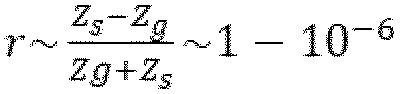
- The attenuation coefficient for air is α~1.84 × 10⁻¹¹/f 2 m -1.
- The gain factor G(f) = R(f)/f for the URAS may be significantly higher at a resonant frequency of the gas, for instance more than 5 times higher or, e.g., about 8.5 times higher than for "surrounding" frequencies. The absorbed power depends on the wavelength of the light. The acoustic pressure depends on the absorbed power and on the acoustic frequency, because an acoustic resonance can occur for some frequencies. In this implementation, the acoustic frequency is the blinking frequency of the LED. The acoustic resonance depends on the sound velocity in the gas, so it will change with the composition and the temperature of the gas in the detector cell. A value of 2833 Hz was obtained for air.
- The URAS comprises a reference light source. The reference light source emits a reference light beam when driven by a reference power source. The reference power source may deliver an alternating current of any waveform, e.g. a sine, a rectangle, a saw tooth or of another waveform. The reference power source may be driven by a controller, so that frequency, waveform and/or amplitude of the reference light beam may be varied. The URAS also comprises a sample light source. The sample light source emits a reference light beam when driven by a sample power source. The sample light source may be of the same type or of a (very) similar type as the reference light source. The sample power source may be driven by the same controller as the reference power source. The two power sources, thus, may have the same frequency, but they may differ in amplitude and/or in phase. This, of course, also applies to the two light sources.
- The reference light beam is configured for passing a reference chamber filled with a reference gas and for reaching a detector chamber filled with a detector gas. The sample light beam is configured for passing the sample chamber, essentially in parallel to the reference light beam that is passing the reference chamber, and also for reaching the detector chamber. The sample chamber is filled with the gas sample. The detector chamber may be filled with any kind of gas or, in some embodiments, with a kind of gas that supports the measurement, i.e. the sensing of the gas sample. In other words, the URAS has at least three gas cells or chambers; one contains the sample gas, another one is the reference cell, which contains the reference gas, and a third one is a plurality of detector cells that contain detection gases. The light emitted by the reference light source and the sample light source travels through the respective one of the gas cells. The detector cell collects the light leaving the gas cell. This light is absorbed by the gas in the detector cell, which triggers a photothermal expansion, and results in a pressure change in the detector cell. A pressure change in a gas is nothing but a sound wave and can, thus, be sensed or captured by a microphone. Accordingly, the microphone is configured for sensing pressure changes in the detector chamber, and the pressure changes are a function of the gas sample, particularly a function of an absorption behaviour of the gas sample. The pressure changes may also depend on the reference light beam and/or the sample light beam, e.g. its blinking frequency and light intensity. The microphone may be part of a wall - e.g. to an outer wall - of the detector chamber and/or may be attached to a separator (or an inner wall) of the detector chamber. The microphone converts the pressure changes to an electric signal.
- The URAS further comprises a control unit. The control unit is configured for receiving an electric output from the microphone; the electric output is caused by the pressure changes in the detector chamber. The control unit is further configured for controlling, depending on the electric output, an amplitude of the reference power source and/or of the sample power source. The control unit may further be configured for controlling frequency, phase and/or further attributes of said power sources and, thus, of the light sources that are connected to the respective power sources. The control unit may, for instance, be able to control the amplitude of the reference power source and/or of the sample power source in a way that the sensed pressure changes in the detector chamber reach a minimum, e.g. a value close to zero.
- This photoacoustic gas sensing apparatus advantageously does not have or need a mechanical chopper. This brings several benefits, for instance less ambient vibrations and/or fewer moving parts. (Some embodiments may not have mechanical parts at all.) This may contribute to significantly longer maintenance intervals of the gas sensing apparatus. Furthermore, this type of gas sensing apparatus may have a longer lifetime than other types. Additionally, this apparatus has a lower vibration noise level than mechanical ones. Besides, this apparatus is able to tolerate manufacturing tolerances of the light source, even manufacturing deviations between the reference light source and the sample light source. Enhancements in infrared LEDs means, e.g. providing LEDs with higher intensities, may lead to a larger signal.
- In various embodiments, the reference light source and/or the sample light source is configured for emitting mid-infrared light, particularly of a wavelength between 2 µm and 15 µm, between 2 µm and 8 µm, between 2.5 µm and 7.5 µm, between 2.8 µm and 4.7 µm. The wavelength of the light sources may depend on the gases to be sensed.
- Note that photoacoustic sensing is not restricted to infrared. In some embodiments, the reference light source and/or the sample light source is configured for emitting ultraviolet light, particularly of a wavelength between 200 nm and 400 nm. This may advantageously enable to sense different gas samples and/or a broad variety of gas samples.
- In various embodiments, the reference light source and/or the sample light source is configured for emitting light of a frequency between 1 kHz and 100 kHz, particularly between 5 kHz and 50 kHz. The power sources - and, thus, the light sources - may deliver an alternating current or a periodic change of any waveform, e.g. a sine, a rectangle, a saw tooth or another waveform. The frequency may depend on the dimensions of the chambers and/or on the gas to be sensed. For instance if the largest dimension of the detector cell is L, then the useful frequency band of the light source is between 0.5 · L/c and 2 · L/c, where c is the sound speed in the detector cell.
- In various embodiments, the reference light source and/or the sample light source is a light-emitting diode, LED. For instance, an LED L15895-0430ML by Hamamatsu may be used, which emits 1.4 mW at 4.3 µm. 33% of its light is absorbed by CO2. In contrast, only 6% of a light bulb's power is absorbed by CO2. But, LEDs not only have an higher efficiency, but can also emit higher frequencies than light bulbs. Furthermore, LEDs have a longer lifetime. i.e. while a lifespan infrared-emitting lightbulbs may range between 2,000 and 10,000 hours (for example, Edmund optics #87-299 and Thorlabs SLS20x series), a typical LED lasts for 100,000 hours, which might result in running the instrument for about 10 years without maintenance.
- In some embodiments, the reference light source and/or the sample light source is of a adjustable wavelength and/or comprises a plurality of light sources. Particularly, each light source of the plurality of light sources may have a different wavelength. This may further increase the sensitivity of the apparatus, because the light source and/or the wavelength that is used for the sensing may be selected depending on the gas to be sensed.
- In various embodiments, the reference gas is nitrogen or a calibrated blend matching the gas to be sensed in the sample cell. For instance, the gas to be sensed and/or analysed could be natural gas, which is supposed to have a constant composition. The reference cell could contain this expected mixture, and therefore the URAS would compare the reference and sample cell and spot any mismatch between them.
- In various embodiments, the detector gas is a gas or a gas mixture having an absorption band that overlaps with the gas to be sensed. Examples may comprise CO2 or SO2, when CO2 or SO2, respectively, is to be sensed. Particularly, the detector gas may need to absorb at the same wavelength as the gas to be sensed. In other words, it may be advantageous when the detector gas has a similar molecular structure locally. However, the detector gas does not need to be of the same species as the gas to be sensed.
- In various embodiments, the sample chamber and/or the reference chamber has a length between 5 cm and 15 cm, particularly about 10 cm, and/or has a diameter between 12.5 mm and 50 mm, particularly about 25 mm. This may be advantageous both for a handling of the apparatus, but also for the selection of the frequency used for the analysis.
- In various embodiments, the sample chamber comprises an inlet opening with a filter arranged therein. This may advantageously contribute to reducing of avoiding particles of dust or dirt in the sample chamber.
- In various embodiments, the microphone is a capacitive or condenser microphone, an electrodynamic microphone, a piezoelectric microphone and/or a flowmeter. It may be taken into consideration that capacitive microphones may be limited at low frequency by a pink (1/f) noise that arises from the white noise of high-value charge-holding resistors filtered by the capacitance of the microphone. Piezoelectric microphones (sometimes called "MEMS microphones") may have benefits, e.g. concerning their robustness. A flowmeter enables to measure the acoustic wave by opening a small channel between the two chambers, and measuring the flow driven by the difference of oscillating pressures in both chambers.
- An aspect relates to a method for sensing a gas sample in a sample chamber by means of a photoacoustic gas sensing apparatus according to any one of the preceding claims, the method comprising the steps of:
Emitting a reference light beam, from a reference light source, which is driven by a reference power source, through a reference chamber filled with a reference gas to a detector chamber filled with a detector gas. - Emitting a sample light beam, from a sample light source, which is driven by a sample power source, through a sample chamber filled with a sample gas to the detector chamber, the sample light beam having a sample amplitude that is proportional to a reference amplitude of the reference light beam. The sample and reference light beams may have the same frequency, but there may be a phase shift between the sample light beam and the reference light beam. Furthermore, the proportionality coefficient between the sample and the reference light beam may be adjusted depending on the readout of the microphone in the detection chamber. If the reference light beam's intensity is Ir = f(t), then the sample light beam intensity is is = Kf(t+phi), where K is a proportionality constant that might be adjusted depending on the microphone output, and phi is the adjustable phase.
- Sensing, by a microphone, pressure changes in the detector chamber, the pressure changes being a function of the gas sample. The pressure changes may be caused by an energy provided by the reference light beam and the sample light beam.
- Receiving, by a control unit, an electric output, caused by the pressure changes, from the microphone.
- Controlling, by the control unit, an amplitude of the reference power source and/or of the sample power source, so that the sensed pressure changes in the detector chamber, caused by a destructive interference of the pressure changes, which are caused by the reference power source and by the sample power source, are at a minimum. The minimum may, e.g., be a value close to zero. Thus, the control unit changes the sample amplitude and/or the reference amplitude in a way that the electric output of the microphone is at a minimum, caused by a destructive interference of the pressure waves. This may further contribute to an increased robustness against manufacturing deviations of the light sources.
- In various embodiments, the method further comprises the step of: Before sensing pressure changes in the detector chamber, exchanging the sample gas in the sample chamber. This step may be conducted right before the sensing step and/or right before the emitting steps.
- An aspect relates to a use of a photoacoustic gas sensing apparatus as described above and/or below for sensing and/or for analysing a gas sample.
- An aspect relates to a non-transitory computer-readable storage medium comprising computer program instructions stored therein, which, when executed on control unit of a photoacoustic gas sensing apparatus and/or on another processor, instructs the apparatus to perform the method described above and/or below.
- It should be noted that two or more embodiments described above and/or below can be combined, as far as technically feasible.
- For further elucidation, the disclosure is described by means of embodiments shown in the figures. These embodiments are to be considered as examples only, but not as limiting.
- The drawings depict:
- Fig. 1
- schematically a photoacoustic gas sensing apparatus according to an embodiment;
- Figs. 2a and 2b
- schematically absorption spectra according to an embodiment;
- Fig. 3
- schematically a photoacoustic gas sensing apparatus according to an embodiment;
- Fig. 4
- a flow diagram according to an embodiment.
-
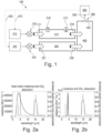
Fig. 1 shows schematically a photoacousticgas sensing apparatus 100 according to an embodiment. Thegas sensing apparatus 100 is configured for sensing a gas sample in asample chamber 310. Theapparatus 100 comprises areference light source 220, which is driven by areference power source 225. Thereference light source 220 emits areference light beam 221, which passes through areference chamber 320 filled with a reference gas and finally reaches adetector chamber 400 filled with a detector gas. Theapparatus 100 further comprises a samplelight source 210, which is driven by asample power source 215. Thesample light source 210 emits asample light beam 211, which passes through thesample chamber 310 filled with the gas sample and finally reaches thedetector chamber 400 filled with a detector gas. Thesample chamber 310 has aninlet opening 312, optionally with a filter arranged therein, and anoutlet opening 318, so that the gas sample can be exchanged. - At an outer wall 450 (e.g. in an opening, as shown), at an inner wall and/or on another position of the
detector chamber 400, amicrophone 500 is arranged, so that pressure changes in thedetector chamber 400 can be sensed. The pressure changes may be a function of the gas sample, particularly a function of an absorption behaviour of the gas sample. Themicrophone 500 sends its electric output, via aline 560, to acontrol unit 600. Thecontrol unit 600 receives the electric output and controls, depending on theelectric output 560, an amplitude of thereference power source 225 and/or of thesample power source 215 vialines -
Figs. 2a and 2b show schematically absorption spectra according to an embodiment.Figs. 2a shows CO2 absorption lines (dotted lines) and an irradiance (solid line) of a black body of 975 K. It is clearly visible that CO2 absorption lines at about 3 and 4.5 µm are stimulated in a higher degree.Figs. 2b shows CO2 absorption lines (dotted lines) and an irradiance (solid line) of an exemplary LED emitting mid-infrared light. In difference to the black body radiator ofFigs. 2a , this LED light has a narrower band and fits better to one characteristic line of the CO2 absorption spectrum. Hence, the precision of recognizing a specific sort of gas is significantly increased by using this light source. This narrow band characteristic of the LED light further provides a chance of a precise adaptation of a light source to the target gas that should be measured. For another type of gas, the light source can be adapted to a specific gas sample - or even a plurality of gases - to be sensed. This adaptation may be achieved, for instance, by using a light source of an adjustable wavelength and/or by using a plurality of light sources, each with different wavelength, from which the light source with the best-fitting wavelength can be selected. -
Fig. 3 shows schematically a photoacousticgas sensing apparatus 100 according to an embodiment. This apparatus is quite similar to theapparatus 100 ofFig. 1 . Same reference signs designate same or similar elements. The main difference toFig. 1 is the design of thedetector chamber 400. In this embodiment, the chamber is divided in a detector and a discrimination chamber, each of which contains a different gas mixture. Using such a combination, it is possible to reduce cross-interference between gases, which is to discriminate between gases that would both have an absorption ray overlap with the detecting gas. For instance, CO2 has two absorption rays, one near 4.7 um and the other near 15 um. If CO2 is used as the detection gas, it can detect species absorbing at any of those two wavelengths. Hence, it cannot discriminate between a species A that would absorb at 4.7 um, and another species B that would absorb at 15 um. To discriminate between A and B, one can compare the absorption of CO2 to the absorption of say CO that absorbs at 4.5 and 4.7 um. If both gases absorb the radiation, then the sample gas has an absorption ray at 4.7 um, but if only CO2 absorbs the radiation, then the sample gas absorbs at 15 um. By carefully adjusting the concentration, the absorption of the discrimination and detection chambers may be matched in order to notch some ambiguous wavelength that both species A and B absorb. -
Fig. 4 shows a flow diagram 700 for sensing a gas sample in a sample chamber 310 (seeFig. 1 orFig. 3 for examples) by means of a photoacousticgas sensing apparatus 100 according to an embodiment. After starting the method, in astep 702, areference light beam 221 is emitted from areference light source 220. In astep 704, asample light beam 211 is emitted from a samplelight source 210. Thesteps reference light beam 221 passes from thereference light source 220 through areference chamber 320 filled with a reference gas to adetector chamber 400 filled with a detector gas. The emittedsample light beam 211 passes from thesample light source 210 through asample chamber 310 filled with a sample gas to thedetector chamber 400. - In a
step 706, the sample gas in thesample chamber 310 is exchanged. This step is conducted before a step 708 (see below). In some embodiments, thestep 706 may be conducted before thesteps step 708, pressure changes in thedetector chamber 400 are sensed by amicrophone 500, wherein the pressure changes are a function of the gas sample. In astep 710, an electric output is received by acontrol unit 600. The electric output is caused by the pressure changes and come from themicrophone 500 via aline 560. In astep 712, thecontrol unit 600 controls an amplitude of thereference power source 225 and/or of thesample power source 215, so that the sensed pressure changes in thedetector chamber 400 are at a minimum. This effect may be caused by a destructive interference of the pressure changes, which are caused by thereference power source 225 and by thesample power source 215. -
- 100
- photoacoustic gas sensing apparatus
- 210
- sample light source
- 211
- sample light beam
- 215
- sample power source
- 220
- reference light source
- 221
- reference light beam
- 225
- reference power source
- 310
- sample chamber
- 312
- inlet opening of the sample chamber
- 318
- outlet opening of the sample chamber
- 320
- reference chamber
- 400
- detector chamber
- 420
- discrimination chamber
- 450
- wall of the detector chamber
- 500
- microphone
- 560
- line
- 600
- control unit
- 615, 625
- control lines
- 700
- flow diagram
- 702-712
- steps
Claims (15)
- A photoacoustic gas sensing apparatus (100) for sensing a gas sample in a sample chamber (310), the apparatus (100) comprising:a reference light source (220), configured for emitting a reference light beam (221) when driven by a reference power source (225),wherein the reference light beam (221) is configured for passing a reference chamber (320) filled with a reference gas and for reaching a detector chamber (400) filled with a detector gas;a sample light source (210), configured for emitting a sample light beam (211) when driven by a sample power source (215),wherein the sample light beam (211) is configured for passing the sample chamber (310) filled with the gas sample and for reaching the detector chamber (400);a microphone (500), configured for sensing pressure changes in the detector chamber (400), the pressure changes being a function of the gas sample; anda control unit (600), configured for receiving an electric output (560), caused by the pressure changes, from the microphone (500), andfor controlling, depending on the electric output (560), an amplitude of the reference power source (225) and/or of the sample power source (215).
- The apparatus (100) of claim 1,
wherein the reference light source (220) and/or the sample light source (210) is configured for emitting mid-infrared light, particularly of a wavelength between 2 µm and 15 µm, between 2 µm and 8 µm, between 2.5 µm and 7.5 µm, between 2.8 µm and 4.7 µm, and/or - The apparatus (100) of claim 1,
wherein the reference light source (220) and/or the sample light source (210) is configured for emitting ultraviolet light, particularly of a wavelength between 200 nm and 400 nm. - The apparatus (100) of any one of the preceding claims,
wherein the reference light source (220) and/or the sample light source (210) is configured for emitting light of a frequency between 1 kHz and 100 kHz, particularly between 5 kHz and 50 kHz. - The apparatus (100) of any one of the preceding claims,
wherein the reference light source (220) and/or the sample light source (210) is a light-emitting diode, LED. - The apparatus (100) of any one of the preceding claims,
wherein the reference light source (220) and/or the sample light source (210) is of an adjustable wavelength and/or comprises a plurality of light sources. - The apparatus (100) of any one of the preceding claims,
wherein the reference gas is nitrogen or a calibrated blend matching the gas to be sensed in the sample cell. - The apparatus (100) of any one of the preceding claims,
wherein the detector gas is a gas or a gas mixture having an absorption band that overlaps with the gas to be sensed. - The apparatus (100) of any one of the preceding claims,wherein the sample chamber (310) and/or the reference chamber (320) has a length between 5 cm and 15 cm, particularly about 10 cm, and/orhas a diameter between 12.5 mm and 50 mm, particularly about 25 mm.
- The apparatus (100) of any one of the preceding claims,
wherein the sample chamber (310) comprises an inlet opening (312) with a filter arranged therein. - The apparatus (100) of any one of the preceding claims,
wherein the microphone (500) is a capacitive microphone, an electrodynamic microphone, a piezoelectric microphone, and/or a flowmeter. - A method for sensing a gas sample in a sample chamber (310) by means of a photoacoustic gas sensing apparatus (100) according to any one of the preceding claims, the method comprising the steps of:emitting a reference light beam (221), from a reference light source (220), which is driven by a reference power source (225), through a reference chamber (320) filled with a reference gas to a detector chamber (400) filled with a detector gas;emitting a sample light beam (211), from a sample light source (210), which is driven by a sample power source (215), through a sample chamber (310) filled with a sample gas to the detector chamber (400), the sample light beam (211) having a sample amplitude that is proportional to a reference amplitude of the reference light beam (221);sensing, by a microphone (500), pressure changes in the detector chamber (400), the pressure changes being a function of the gas sample;receiving, by a control unit (600), an electric output (560), caused by the pressure changes, from the microphone (500); andcontrolling, by the control unit (600), an amplitude of the reference power source (225) and/or of the sample power source (215), so that the sensed pressure changes in the detector chamber (400), caused by a destructive interference of the pressure changes, which are caused by the reference power source (225) and by the sample power source (215), are at a minimum.
- The method of claim 12, further comprising the step of:
before sensing pressure changes in the detector chamber (400), exchanging the sample gas in the sample chamber (310). - Use of a photoacoustic gas sensing apparatus (100) according to any one of the claims 2 - 11 for sensing and/or for analysing a gas sample.
- A non-transitory computer-readable storage medium comprising computer program instructions stored therein, which, when executed on control unit (600) of a photoacoustic gas sensing apparatus (100) and/or on another processor, instructs the apparatus (100) to perform the method according to claim 12 or 13.
Priority Applications (1)
| Application Number | Priority Date | Filing Date | Title |
|---|---|---|---|
| EP23201530.5A EP4534978A1 (en) | 2023-10-04 | 2023-10-04 | A photoacoustic gas sensing apparatus |
Applications Claiming Priority (1)
| Application Number | Priority Date | Filing Date | Title |
|---|---|---|---|
| EP23201530.5A EP4534978A1 (en) | 2023-10-04 | 2023-10-04 | A photoacoustic gas sensing apparatus |
Publications (1)
| Publication Number | Publication Date |
|---|---|
| EP4534978A1 true EP4534978A1 (en) | 2025-04-09 |
Family
ID=88287259
Family Applications (1)
| Application Number | Title | Priority Date | Filing Date |
|---|---|---|---|
| EP23201530.5A Pending EP4534978A1 (en) | 2023-10-04 | 2023-10-04 | A photoacoustic gas sensing apparatus |
Country Status (1)
| Country | Link |
|---|---|
| EP (1) | EP4534978A1 (en) |
Citations (7)
| Publication number | Priority date | Publication date | Assignee | Title |
|---|---|---|---|---|
| US3897153A (en) * | 1973-07-23 | 1975-07-29 | Beckman Instruments Inc | Phase and amplitude balance adjustment for a dual beam infrared gas analyzer |
| US3995960A (en) * | 1975-07-25 | 1976-12-07 | Nasa | Method and apparatus for background signal reduction in opto-acoustic absorption measurement |
| EP0053677A1 (en) * | 1980-12-08 | 1982-06-16 | Siemens Aktiengesellschaft | Non-dispersive infrared gas analyzer |
| US6006585A (en) * | 1997-01-25 | 1999-12-28 | Cerberus Ag | Optoacoustic gas sensor |
| WO2005093390A1 (en) * | 2004-03-29 | 2005-10-06 | Noveltech Solutions Oy | Method and system for detecting one or more gases or gas mixtures and/or for measuring the concentration of one or more gases or gas mixtures |
| JP2006329913A (en) * | 2005-05-30 | 2006-12-07 | Yokogawa Electric Corp | Infrared gas analyzer |
| US20180284012A1 (en) * | 2015-09-10 | 2018-10-04 | Honeywell International Inc. | Gas detector with normalized response and improved sensitivity |
-
2023
- 2023-10-04 EP EP23201530.5A patent/EP4534978A1/en active Pending
Patent Citations (7)
| Publication number | Priority date | Publication date | Assignee | Title |
|---|---|---|---|---|
| US3897153A (en) * | 1973-07-23 | 1975-07-29 | Beckman Instruments Inc | Phase and amplitude balance adjustment for a dual beam infrared gas analyzer |
| US3995960A (en) * | 1975-07-25 | 1976-12-07 | Nasa | Method and apparatus for background signal reduction in opto-acoustic absorption measurement |
| EP0053677A1 (en) * | 1980-12-08 | 1982-06-16 | Siemens Aktiengesellschaft | Non-dispersive infrared gas analyzer |
| US6006585A (en) * | 1997-01-25 | 1999-12-28 | Cerberus Ag | Optoacoustic gas sensor |
| WO2005093390A1 (en) * | 2004-03-29 | 2005-10-06 | Noveltech Solutions Oy | Method and system for detecting one or more gases or gas mixtures and/or for measuring the concentration of one or more gases or gas mixtures |
| JP2006329913A (en) * | 2005-05-30 | 2006-12-07 | Yokogawa Electric Corp | Infrared gas analyzer |
| US20180284012A1 (en) * | 2015-09-10 | 2018-10-04 | Honeywell International Inc. | Gas detector with normalized response and improved sensitivity |
Similar Documents
| Publication | Publication Date | Title |
|---|---|---|
| EP2157419B1 (en) | Photoacoustic sensor | |
| US11300499B2 (en) | Multi-cavity semi-open resonant photoacoustic cell and multi-gas simultaneous measurement system | |
| CN104237135B (en) | CO gas detecting systems and method based on quartz tuning fork strengthened optoacoustic spectroscopy | |
| US7895880B2 (en) | Photoacoustic cell incorporating a quantum dot substrate | |
| US11061002B2 (en) | Photoacoustic gas analyzer for determining species concentrations using intensity modulation | |
| KR100419094B1 (en) | gas identification device | |
| JPH09127066A (en) | Optoacoustic gas sensor and method of application thereof | |
| US7782462B2 (en) | Sono-photonic gas sensor | |
| CN102759508B (en) | Photoacoustic sensors with adaptive operating frequency | |
| CN104422658B (en) | Detect the method and system of the component in fluid | |
| CN102539338A (en) | Online monitoring system for gas content in transformer oil by using photoacoustic spectrum | |
| CN104422668A (en) | Method and system for detecting of components in fluid | |
| KR101635656B1 (en) | An apparatus adapted for spectral analysis of high concentrations of gas | |
| CN107796762B (en) | Gas analyzer | |
| CN101813618A (en) | Device and method for simultaneously detecting plurality of gases based on optoacoustic effect | |
| EP4534978A1 (en) | A photoacoustic gas sensing apparatus | |
| JP2012237684A (en) | Concentration measurement device | |
| CN210269590U (en) | Double-cell series photoacoustic spectroscopy gas detection device | |
| US10996201B2 (en) | Photoacoustic measurement systems and methods using the photoacoustic effect to measure emission intensities, gas concentrations, and distances | |
| KR100351975B1 (en) | Opto-acoustic gas analyzer | |
| CN117405619A (en) | Multi-component infrared gas analysis method and device based on wavelength modulation technology | |
| Huber et al. | A selective, miniaturized, low-cost detection element for a photoacoustic CO2 sensor for room climate monitoring | |
| CN108426850A (en) | CO in a kind of absolute measurement air2The frequency stabilization cavity ring-down spectroscopy instrument of content | |
| CN116804628A (en) | Device and method for improving LIBS quantitative detection precision and reducing self-absorption influence | |
| Ma et al. | Investigation of trace gas sensor based on QEPAS method using different QTFs |
Legal Events
| Date | Code | Title | Description |
|---|---|---|---|
| PUAI | Public reference made under article 153(3) epc to a published international application that has entered the european phase |
Free format text: ORIGINAL CODE: 0009012 |
|
| STAA | Information on the status of an ep patent application or granted ep patent |
Free format text: STATUS: THE APPLICATION HAS BEEN PUBLISHED |
|
| AK | Designated contracting states |
Kind code of ref document: A1 Designated state(s): AL AT BE BG CH CY CZ DE DK EE ES FI FR GB GR HR HU IE IS IT LI LT LU LV MC ME MK MT NL NO PL PT RO RS SE SI SK SM TR |
|
| STAA | Information on the status of an ep patent application or granted ep patent |
Free format text: STATUS: REQUEST FOR EXAMINATION WAS MADE |
|
| 17P | Request for examination filed |
Effective date: 20250903 |