EP4534961A1 - Article retaining apparatus - Google Patents
Article retaining apparatus Download PDFInfo
- Publication number
- EP4534961A1 EP4534961A1 EP24202981.7A EP24202981A EP4534961A1 EP 4534961 A1 EP4534961 A1 EP 4534961A1 EP 24202981 A EP24202981 A EP 24202981A EP 4534961 A1 EP4534961 A1 EP 4534961A1
- Authority
- EP
- European Patent Office
- Prior art keywords
- hopper
- extending portion
- guide
- article
- supporting body
- Prior art date
- Legal status (The legal status is an assumption and is not a legal conclusion. Google has not performed a legal analysis and makes no representation as to the accuracy of the status listed.)
- Pending
Links
Images





Classifications
-
- G—PHYSICS
- G01—MEASURING; TESTING
- G01G—WEIGHING
- G01G19/00—Weighing apparatus or methods adapted for special purposes not provided for in the preceding groups
- G01G19/387—Weighing apparatus or methods adapted for special purposes not provided for in the preceding groups for combinatorial weighing, i.e. selecting a combination of articles whose total weight or number is closest to a desired value
- G01G19/393—Weighing apparatus or methods adapted for special purposes not provided for in the preceding groups for combinatorial weighing, i.e. selecting a combination of articles whose total weight or number is closest to a desired value using two or more weighing units
Definitions
- the present invention relates to an article retaining apparatus.
- a combination weighing apparatus having a configuration in which a booster hopper is attached to a supporting body from the upper side in the vertical direction is known.
- Patent Literature 1 JP 6982923 B2
- such a combination weighing apparatus has a problem that it is difficult for an operator to visually recognize the attachment position of the booster hopper, and thus the booster hopper may fail to be correctly attached to the supporting body provided at the main body.
- a gate 14 remains open. In this state, the operator brings the booster hopper 10 close to the supporting body 20.
- the supporting body 20 is provided at the lower portion of the combination weighing apparatus 1.
- the operator brings the booster hopper 10 close to the supporting body 20 in a path from the upper side to the lower side in the substantially vertical direction.
- the gate 14 remains open.
- the control unit (not illustrated) of the combination weighing apparatus 1 is not configured to recognize the erroneous attachment of the booster hopper 10 as described above.
- the combination weighing operation is performed while an object to be weighed fails to be stored in the booster hopper 10.
- a skilled operator may find erroneous attachment, but an inexperienced operator may overlook erroneous attachment.
- the lever 22 of the booster hopper 10 moves, the lever 22 lifts the booster hopper 10, and in the worst case, the booster hopper 10 is disengaged and falls from the supporting body 20.
- the present invention has been made in view of the above problems, and an object of the present invention is to provide an article retaining apparatus that can reduce erroneous attachment of a hopper and shorten attachment time of the hopper.
- An article retaining apparatus includes: a hopper configured to temporarily retain an article and discharge the article; a supporting body configured to support the hopper in an attachable and detachable manner, and a guide, characterized in that the hopper includes: a main body configured to retain the article, and an extending portion extending along a width direction of the main body, the supporting body includes an engaging portion configured to engage with the extending portion at an engagement position, and the guide is disposed at a predetermined space with respect to an upper side of the engaging portion in a vertical direction, and when the extending portion approaches the engaging portion from the upper side in the vertical direction, the guide temporarily obstructs engagement of the extending portion and the engaging portion, and then moves the extending portion in a reverse direction of an attaching direction of the hopper to guide the extending portion to the engagement position.
- the combination weighing apparatus is an apparatus that calculates an article supplied from a conveyor disposed upstream so that an article has a target weight value, and supplies the calculated article to a downstream apparatus.
- the article retaining apparatus 1 includes a hopper 10, a supporting body 20, a guide 30, a drive unit 40, and a drive unit 50. Note that the function of the drive unit 40 and the function of the drive unit 50 may be included in one drive unit.
- the hopper 10 temporarily retains an article and discharges the article.
- the hopper 10 is a booster hopper, but may be another hopper.
- the hopper 10 includes a main body 11 for retaining an article and an extending portion 12 extending along a width direction W (see Fig. 1 ) of the main body 11.
- the extending portion 12 is a columnar member.
- the extending portion 12 may be a prism-shaped member other than the columnar member.
- the sectional shape of the extending portion 12 is not limited as long as the extending portion 12 is a member that engages with an engagement position 21A.
- the supporting body 20 is provided at the drive unit 50 and supports the hopper 10 in an attachable and detachable manner. As illustrated in Figs. 1 to 6 , the supporting body 20 includes an engaging portion 21 that engages with the extending portion 12 at the engagement position 21A.
- the guide 30 is disposed at a predetermined space T with respect to the upper side of the engaging portion 21 in the vertical direction. Specifically, the provided space makes it possible, at least, to insert the extending portion 12 to the engagement position 21A of the engaging portion 21.
- the guide 30 When the extending portion 12 approaches the engaging portion 21 from the upper side in the vertical direction, the guide 30 temporarily obstructs the engagement between the extending portion 12 and the engaging portion 21. The guide 30 then moves the extending portion 12 in a reverse direction D1 of the attaching direction of the hopper 10 and guides the extending portion 12 to the engagement position 21A.
- the guide 30 may be attached by using a bolt 41 of the drive unit 40 of an upstream hopper (e.g., a weighing hopper) disposed above the hopper 10.
- an upstream hopper e.g., a weighing hopper
- the guide 30 may be welded to the drive unit 40, or the guide 30 may be formed integrally with the drive unit 40. In short, the guide 30 may have any configuration as long as the guide 30 is directly or indirectly coupled to the drive unit 40.
- the hopper 10 includes a gate 14 and a roller 13 for opening and closing the gate 14.
- the drive unit 50 opens and closes the gate 14 included in the hopper 10.
- the supporting body 20 includes a lever 22 that opens and closes the gate 14 by moving the roller 13.
- the roller 13 may slide downward in a state of being in contact with the outer side of the lever 22, and be fitted into a recess 22A provided at the lever 22.
- the roller 13 when the extending portion 12 is engaged with the engagement position 21A, the roller 13 can also be correctly fitted into the recess 22A, and the hopper 10 can be correctly attached to the supporting body 20.
- an end 30E of the guide 30 may be disposed on the reverse direction D1 side of the attaching direction of the hopper 10 with respect to an end 20E of the supporting body 20.
- Such a configuration can avoid accidental fall of the hopper 10 when the extending portion 12 approaching from the upper side of the guide 30 in the vertical direction moves in the reverse direction D1 of the attaching direction of the hopper 10 by the action of the guide 30 and falls to the lower side in the vertical direction.
- the hopper 10 starts falling due to the own weight thereof.
- the end 20E of the supporting body 20 is disposed on the reverse direction D1 side of the attaching direction of the hopper 10 with respect to the end 30E of the guide 30, the hopper 10 is received by the fall protection surface including the end 30E of the guide 30.
- the guide 30 includes a portion 30A attached to the bolt 41 and a portion 30B rising from the portion 30A in the reverse direction D1 of the attaching direction of the hopper 10.
- the portion 30B may have a slope shape descending toward the reverse direction D1 of the attaching direction of the hopper 10.
- the area where the positioning of the hopper 10 is performed spreads over the entire area including the guide 30.
- the hopper 10 moves downward in the vertical direction along the slope and can be attached to the engagement position 21A by following the movement.
- the operator brings the hopper 10 close to the supporting body 20 in a path from the upper side to the lower side in the substantially vertical direction in a state in which the gate 14 remains open.
- the extending portion 12 of the hopper 10 comes into contact with the guide 30 (portion 30B), and the engagement between the extending portion 12 and the engaging portion 21 is temporarily obstructed.
- the extending portion 12 moves in the reverse direction D1 of the attaching direction of the hopper 10. At this time, the roller 13 slides downward while being in contact with the outer side of the lever 22.
- the extending portion 12 slides downward in the vertical direction and comes into contact with the engaging portion 21.
- the operator slides the extending portion 12 in an attaching direction D2 of the hopper 10, and then the extending portion 12 is engaged with the engagement position 21A, and the roller 13 is fitted into the recess 22A provided at the lever 22.
- the gate 14 is closed, and the hopper 10 is correctly attached to the supporting body 20. After this series of processes, the gate 14 opens and closes by moving the lever 22 up and down.
- erroneous attachment of the hopper 10 can be reduced, and attachment time of the hopper 10 can be shortened.
Landscapes
- Physics & Mathematics (AREA)
- General Physics & Mathematics (AREA)
- Filling Or Emptying Of Bunkers, Hoppers, And Tanks (AREA)
Abstract
Description
- The present invention relates to an article retaining apparatus.
- In the related art, a combination weighing apparatus having a configuration in which a booster hopper is attached to a supporting body from the upper side in the vertical direction is known.
- Patent Literature 1:
JP 6982923 B2 - However, such a combination weighing apparatus has a problem that it is difficult for an operator to visually recognize the attachment position of the booster hopper, and thus the booster hopper may fail to be correctly attached to the supporting body provided at the main body.
- Here, a case in which a booster hopper 10 fails to be correctly attached to a supporting
body 20 in such a combination weighing apparatus 1 will be described with reference toFigs. 7 to 9 . - As illustrated in
Fig. 7 , when the operator holds thebooster hopper 10, agate 14 remains open. In this state, the operator brings thebooster hopper 10 close to the supportingbody 20. - At this time, as illustrated in
Figs. 7 and8 the supportingbody 20 is provided at the lower portion of the combination weighing apparatus 1. Thus, the operator brings the booster hopper 10 close to the supportingbody 20 in a path from the upper side to the lower side in the substantially vertical direction. - Here, as illustrated in
Fig. 9 , when the operator tries to attach an extendingportion 12 of thebooster hopper 10 to anengagement position 21A of anengaging portion 21 of the supportingbody 20 in such a path, aroller 13 of thebooster hopper 10 is caught by aprotrusion 22X provided at alever 22. - In this state, as illustrated in
Fig. 9 , thegate 14 remains open. Here, the control unit (not illustrated) of the combination weighing apparatus 1 is not configured to recognize the erroneous attachment of thebooster hopper 10 as described above. Thus, the combination weighing operation is performed while an object to be weighed fails to be stored in thebooster hopper 10. A skilled operator may find erroneous attachment, but an inexperienced operator may overlook erroneous attachment. - Further, when the
lever 22 of the booster hopper 10 moves, thelever 22 lifts the booster hopper 10, and in the worst case, thebooster hopper 10 is disengaged and falls from the supportingbody 20. - The present invention has been made in view of the above problems, and an object of the present invention is to provide an article retaining apparatus that can reduce erroneous attachment of a hopper and shorten attachment time of the hopper.
- An article retaining apparatus according to an embodiment is summarized as an article retaining apparatus includes: a hopper configured to temporarily retain an article and discharge the article; a supporting body configured to support the hopper in an attachable and detachable manner, and a guide, characterized in that the hopper includes: a main body configured to retain the article, and an extending portion extending along a width direction of the main body, the supporting body includes an engaging portion configured to engage with the extending portion at an engagement position, and the guide is disposed at a predetermined space with respect to an upper side of the engaging portion in a vertical direction, and when the extending portion approaches the engaging portion from the upper side in the vertical direction, the guide temporarily obstructs engagement of the extending portion and the engaging portion, and then moves the extending portion in a reverse direction of an attaching direction of the hopper to guide the extending portion to the engagement position.
- According to the present invention, it is possible to provide an article retaining apparatus that can reduce erroneous attachment of a hopper and shorten attachment time of the hopper.
-
-
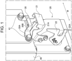
Fig. 1 is a diagram for describing an example of a schematic configuration of a combination weighing apparatus (article retaining apparatus) 1 according to an embodiment. -
Fig. 2 is a diagram for describing an example of an operation of the combination weighing apparatus (article retaining apparatus) 1 according to the embodiment. -
Fig. 3 is a diagram for describing the example of the operation of the combination weighing apparatus (article retaining apparatus) 1 according to the embodiment. -
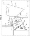
Fig. 4 is a diagram for describing the example of the operation of the combination weighing apparatus (article retaining apparatus) 1 according to the embodiment. -
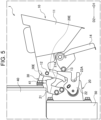
Fig. 5 is a diagram for describing the example of the operation of the combination weighing apparatus (article retaining apparatus) 1 according to the embodiment. -
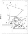
Fig. 6 is a diagram for describing the example of the operation of the combination weighing apparatus (article retaining apparatus) 1 according to the embodiment. -
Fig. 7 is a diagram for describing an example of an operation of a known article retaining apparatus. -
Fig. 8 is a diagram for describing the example of the operation of the known article retaining apparatus. -
Fig. 9 is a diagram for describing the example of the operation of the known article retaining apparatus. - Hereinafter, the present embodiment will be described in detail with reference to the attached drawings. In the following description of the drawings, the same or similar parts are denoted by the same or similar reference symbols. However, note that the drawings are schematic, and ratios of dimensions are different from actual ones. Therefore, specific dimensions and the like are determined in consideration of the following description. Moreover, there may be portions where dimensional relationships or proportions are different among the drawings. In this specification and the drawings, elements having substantially the same function and configuration are denoted by the same reference numerals to omit redundant description, and elements not directly related to the present invention are omitted.
- Hereinafter, an article retaining apparatus 1 according to a first embodiment of the present invention will be described with reference to
Figs. 1 to 6 . In the present embodiment, a combination weighing apparatus will be described as an example of the article retaining apparatus 1, but the present invention is not limited thereto. Note that the combination weighing apparatus is an apparatus that calculates an article supplied from a conveyor disposed upstream so that an article has a target weight value, and supplies the calculated article to a downstream apparatus. - As illustrated in
Figs. 1 to 6 , the article retaining apparatus 1 according to the present embodiment includes ahopper 10, a supportingbody 20, aguide 30, adrive unit 40, and adrive unit 50. Note that the function of thedrive unit 40 and the function of thedrive unit 50 may be included in one drive unit. - The
hopper 10 temporarily retains an article and discharges the article. For example, thehopper 10 is a booster hopper, but may be another hopper. - As illustrated in
Figs. 2 to 6 , thehopper 10 includes amain body 11 for retaining an article and an extendingportion 12 extending along a width direction W (seeFig. 1 ) of themain body 11. In the present embodiment, the extendingportion 12 is a columnar member. Note that the extendingportion 12 may be a prism-shaped member other than the columnar member. In short, the sectional shape of the extendingportion 12 is not limited as long as the extendingportion 12 is a member that engages with anengagement position 21A. - As illustrated in
Figs. 2 to 6 , the supportingbody 20 is provided at thedrive unit 50 and supports thehopper 10 in an attachable and detachable manner. As illustrated inFigs. 1 to 6 , the supportingbody 20 includes anengaging portion 21 that engages with the extendingportion 12 at theengagement position 21A. - As illustrated in
Figs. 2 to 6 , theguide 30 is disposed at a predetermined space T with respect to the upper side of theengaging portion 21 in the vertical direction. Specifically, the provided space makes it possible, at least, to insert the extendingportion 12 to theengagement position 21A of theengaging portion 21. - When the extending
portion 12 approaches theengaging portion 21 from the upper side in the vertical direction, theguide 30 temporarily obstructs the engagement between the extendingportion 12 and theengaging portion 21. Theguide 30 then moves the extendingportion 12 in a reverse direction D1 of the attaching direction of thehopper 10 and guides the extendingportion 12 to theengagement position 21A. - As illustrated in
Figs. 1 to 6 , theguide 30 may be attached by using abolt 41 of thedrive unit 40 of an upstream hopper (e.g., a weighing hopper) disposed above thehopper 10. This configuration eliminates the necessity of providing a new member for attaching theguide 30. - In the above description, the
guide 30 may be welded to thedrive unit 40, or theguide 30 may be formed integrally with thedrive unit 40. In short, theguide 30 may have any configuration as long as theguide 30 is directly or indirectly coupled to thedrive unit 40. - As illustrated in
Figs. 2 to 6 , thehopper 10 includes agate 14 and aroller 13 for opening and closing thegate 14. - The
drive unit 50 opens and closes thegate 14 included in thehopper 10. As illustrated inFigs. 1 to 6 , the supportingbody 20 includes alever 22 that opens and closes thegate 14 by moving theroller 13. - As illustrated in
Figs. 2 to 6 , when the extendingportion 12 is guided to theengagement position 21A, theroller 13 may slide downward in a state of being in contact with the outer side of thelever 22, and be fitted into arecess 22A provided at thelever 22. - According to such a configuration, when the extending
portion 12 is engaged with theengagement position 21A, theroller 13 can also be correctly fitted into therecess 22A, and thehopper 10 can be correctly attached to the supportingbody 20. - As illustrated in
Figs. 2 to 6 , when thedrive unit 40/50 is viewed from the side, anend 30E of theguide 30 may be disposed on the reverse direction D1 side of the attaching direction of thehopper 10 with respect to anend 20E of the supportingbody 20. - Such a configuration can avoid accidental fall of the
hopper 10 when the extendingportion 12 approaching from the upper side of theguide 30 in the vertical direction moves in the reverse direction D1 of the attaching direction of thehopper 10 by the action of theguide 30 and falls to the lower side in the vertical direction. - Specifically, when the extending
portion 12 moves in the reverse direction D1 and deviates from theguide 30, thehopper 10 starts falling due to the own weight thereof. At this time, theend 20E of the supportingbody 20 is disposed on the reverse direction D1 side of the attaching direction of thehopper 10 with respect to theend 30E of theguide 30, thehopper 10 is received by the fall protection surface including theend 30E of theguide 30. - As illustrated in
Fig. 1 , theguide 30 includes aportion 30A attached to thebolt 41 and aportion 30B rising from theportion 30A in the reverse direction D1 of the attaching direction of thehopper 10. Here, theportion 30B may have a slope shape descending toward the reverse direction D1 of the attaching direction of thehopper 10. - According to such a configuration, the area where the positioning of the
hopper 10 is performed spreads over the entire area including theguide 30. When the operator tentatively places thehopper 10 on theportion 30B and loosens the holding force, thehopper 10 moves downward in the vertical direction along the slope and can be attached to theengagement position 21A by following the movement. - Hereinafter, an example of the operation of the article retaining apparatus 1 when the operator attaches the
hopper 10 to the supportingbody 20 will be described with reference toFigs. 2 to 6 . - First, as illustrated in
Fig. 2 , the operator brings thehopper 10 close to the supportingbody 20 in a path from the upper side to the lower side in the substantially vertical direction in a state in which thegate 14 remains open. - Second, as illustrated in
Fig. 3 , the extendingportion 12 of thehopper 10 comes into contact with the guide 30 (portion 30B), and the engagement between the extendingportion 12 and the engagingportion 21 is temporarily obstructed. - Third, as illustrated in
Fig. 4 , the extendingportion 12 moves in the reverse direction D1 of the attaching direction of thehopper 10. At this time, theroller 13 slides downward while being in contact with the outer side of thelever 22. - Fourth, as illustrated in
Fig. 5 , the extendingportion 12 slides downward in the vertical direction and comes into contact with the engagingportion 21. - Fifth, as illustrated in
Fig. 6 , the operator slides the extendingportion 12 in an attaching direction D2 of thehopper 10, and then the extendingportion 12 is engaged with theengagement position 21A, and theroller 13 is fitted into therecess 22A provided at thelever 22. - As a result, the
gate 14 is closed, and thehopper 10 is correctly attached to the supportingbody 20. After this series of processes, thegate 14 opens and closes by moving thelever 22 up and down. - According to the article retaining apparatus 1 of the present embodiment, erroneous attachment of the
hopper 10 can be reduced, and attachment time of thehopper 10 can be shortened. - Although the present invention is explained in detail using the above-mentioned embodiments, it will be apparent to those skilled in the art that the present invention is not limited to the embodiments described herein. The present invention can be implemented as modifications and changes without departing from the spirit and scope of the present invention defined by the description of the claims. Accordingly, the description of the present specification is for the purpose of illustration and is not intended to limit the present invention in any way.
-
- 1
- article retaining apparatus
- 10
- hopper
- 11
- main body
- 12
- extending portion
- 13
- roller
- 14
- gate
- 20
- supporting body
- 20E
- end of supporting body
- 21
- engaging portion
- 21A
- engagement position
- 22
- lever
- 22A
- recess
- 30
- guide
- 30E
- end of guide
- 40
- drive unit of upstream hopper
- 41
- bolt
- 50
- drive unit
Claims (4)
- An article retaining apparatus (1) comprising:a hopper (10) configured to temporarily retain an article and discharge the article;a supporting body (20) configured to support the hopper (10) in an attachable and detachable manner, anda guide (30), characterized in thatthe hopper (10) includes:a main body (11) configured to retain the article, andan extending portion (12) extending along a width direction (W) of the main body (11),the supporting body (20) includes an engaging portion (21) configured to engage with the extending portion (12) at an engagement position (21A), andthe guide (30) is disposed at a predetermined space (T) with respect to an upper side of the engaging portion (21) in a vertical direction, andwhen the extending portion (12) approaches the engaging portion (21) from the upper side in the vertical direction, the guide (30) temporarily obstructs engagement of the extending portion (12) and the engaging portion (21), and then moves the extending portion (12) in a reverse direction (D1) of an attaching direction (D2) of the hopper (10) to guide the extending portion (12) to the engagement position (21A).
- The article retaining apparatus (1) according to claim 1, characterized in that
the guide (30) is attached by using a bolt (41) of a drive unit (40) of an upstream hopper disposed above the hopper (10). - The article retaining apparatus (1) according to claim 2, further comprising:a drive unit (50) configured to open and close a gate (14) included in the hopper (10), whereinthe hopper (10) includes a roller (13) configured to open and close the gate (14),the supporting body (20) includes a lever (22) configured to open and close the gate (14) by moving the roller (13), andwhen the extending portion (12) is guided to the engagement position (21A), the roller (13) slides downward in a state of being in contact with an outer side of the lever (22) and is fitted into a recess (22A) provided at the lever (22).
- The article retaining apparatus (1) according to any of the preceding claims, characterized in that
an end (30E) of the guide (30) is disposed on the reverse direction (D1) side of the attaching direction (D2) of the hopper (10) with respect to an end (20E) of the supporting body (20) when the drive unit (50) is viewed from a side.
Applications Claiming Priority (1)
| Application Number | Priority Date | Filing Date | Title |
|---|---|---|---|
| JP2023171611A JP2025062491A (en) | 2023-10-02 | 2023-10-02 | Article retention device |
Publications (1)
| Publication Number | Publication Date |
|---|---|
| EP4534961A1 true EP4534961A1 (en) | 2025-04-09 |
Family
ID=92926163
Family Applications (1)
| Application Number | Title | Priority Date | Filing Date |
|---|---|---|---|
| EP24202981.7A Pending EP4534961A1 (en) | 2023-10-02 | 2024-09-26 | Article retaining apparatus |
Country Status (2)
| Country | Link |
|---|---|
| EP (1) | EP4534961A1 (en) |
| JP (1) | JP2025062491A (en) |
Citations (2)
| Publication number | Priority date | Publication date | Assignee | Title |
|---|---|---|---|---|
| EP3875923A1 (en) * | 2019-09-26 | 2021-09-08 | ISHIDA CO., Ltd. | Article retaining device and supporting body |
| EP4137785A1 (en) * | 2020-04-17 | 2023-02-22 | Yamato Scale Co., Ltd. | Hopper attachment structure and weighing device comprising same |
-
2023
- 2023-10-02 JP JP2023171611A patent/JP2025062491A/en active Pending
-
2024
- 2024-09-26 EP EP24202981.7A patent/EP4534961A1/en active Pending
Patent Citations (3)
| Publication number | Priority date | Publication date | Assignee | Title |
|---|---|---|---|---|
| EP3875923A1 (en) * | 2019-09-26 | 2021-09-08 | ISHIDA CO., Ltd. | Article retaining device and supporting body |
| JP6982923B2 (en) | 2019-09-26 | 2021-12-17 | 株式会社イシダ | Article retention device and support |
| EP4137785A1 (en) * | 2020-04-17 | 2023-02-22 | Yamato Scale Co., Ltd. | Hopper attachment structure and weighing device comprising same |
Also Published As
| Publication number | Publication date |
|---|---|
| JP2025062491A (en) | 2025-04-14 |
Similar Documents
| Publication | Publication Date | Title |
|---|---|---|
| DE69921556T2 (en) | Stat pendulum adapter and transport device | |
| PL2197753T3 (en) | Improvements relating to packaging | |
| EP2452898A1 (en) | Ceiling conveyor car | |
| KR20120102672A (en) | Fastener dispensing apparatus | |
| EP0999733A1 (en) | Part mounting machine | |
| WO2010080278A1 (en) | Self-adjusting stripper pin for strapping machine strap chute | |
| DE10027485A1 (en) | Device for monitoring a conveyor belt for a bulk material such as stone or ore consists on an opto-electronic camera mounted above an area where damage could occur due to oversize or foreign material | |
| US7334314B2 (en) | Work treatment installation | |
| CN110382150B (en) | Rebar cutting machines and rebar cutting devices | |
| KR20010089555A (en) | Method and device for part transportation | |
| KR20180121832A (en) | Part assembling apparatus | |
| JP2025062491A (en) | Article retention device | |
| EP3875923B1 (en) | Supporting body and article retaining device | |
| US8022328B2 (en) | Device for detecting faulty position and separating fasteners and spacers as well as method | |
| SE456815B (en) | DEVICE FOR TRANSPORT | |
| US20190002212A1 (en) | Stopper | |
| EP2022656A1 (en) | Open roof construction | |
| KR20230151186A (en) | Auto feeder for ring type parts | |
| EP3995794A1 (en) | Combination weighing apparatus | |
| CZ20003205A3 (en) | Feed chute of charging system for waste incinerating plant with cutting device and operation process thereof | |
| EP1810773A1 (en) | Projection nut feeder | |
| CN223015825U (en) | A stepped feeding device for preventing stuck parts | |
| KR101988800B1 (en) | Pipe isolation apparatus | |
| CN223801687U (en) | A cutting device with anti-nail function | |
| CN224257563U (en) | A vibratory plate |
Legal Events
| Date | Code | Title | Description |
|---|---|---|---|
| PUAI | Public reference made under article 153(3) epc to a published international application that has entered the european phase |
Free format text: ORIGINAL CODE: 0009012 |
|
| STAA | Information on the status of an ep patent application or granted ep patent |
Free format text: STATUS: REQUEST FOR EXAMINATION WAS MADE |
|
| 17P | Request for examination filed |
Effective date: 20240926 |
|
| AK | Designated contracting states |
Kind code of ref document: A1 Designated state(s): AL AT BE BG CH CY CZ DE DK EE ES FI FR GB GR HR HU IE IS IT LI LT LU LV MC ME MK MT NL NO PL PT RO RS SE SI SK SM TR |
|
| GRAP | Despatch of communication of intention to grant a patent |
Free format text: ORIGINAL CODE: EPIDOSNIGR1 |
|
| STAA | Information on the status of an ep patent application or granted ep patent |
Free format text: STATUS: GRANT OF PATENT IS INTENDED |
|
| INTG | Intention to grant announced |
Effective date: 20260115 |
|
| GRAS | Grant fee paid |
Free format text: ORIGINAL CODE: EPIDOSNIGR3 |
|
| GRAA | (expected) grant |
Free format text: ORIGINAL CODE: 0009210 |
|
| STAA | Information on the status of an ep patent application or granted ep patent |
Free format text: STATUS: THE PATENT HAS BEEN GRANTED |