EP4534949A1 - Coordinate measuring machine with operation state display system - Google Patents
Coordinate measuring machine with operation state display system Download PDFInfo
- Publication number
- EP4534949A1 EP4534949A1 EP24203333.0A EP24203333A EP4534949A1 EP 4534949 A1 EP4534949 A1 EP 4534949A1 EP 24203333 A EP24203333 A EP 24203333A EP 4534949 A1 EP4534949 A1 EP 4534949A1
- Authority
- EP
- European Patent Office
- Prior art keywords
- machine
- state
- measuring
- indicator
- measuring head
- Prior art date
- Legal status (The legal status is an assumption and is not a legal conclusion. Google has not performed a legal analysis and makes no representation as to the accuracy of the status listed.)
- Pending
Links
Images


Classifications
-
- G—PHYSICS
- G01—MEASURING; TESTING
- G01B—MEASURING LENGTH, THICKNESS OR SIMILAR LINEAR DIMENSIONS; MEASURING ANGLES; MEASURING AREAS; MEASURING IRREGULARITIES OF SURFACES OR CONTOURS
- G01B21/00—Measuring arrangements or details thereof, where the measuring technique is not covered by the other groups of this subclass, unspecified or not relevant
- G01B21/02—Measuring arrangements or details thereof, where the measuring technique is not covered by the other groups of this subclass, unspecified or not relevant for measuring length, width, or thickness
- G01B21/04—Measuring arrangements or details thereof, where the measuring technique is not covered by the other groups of this subclass, unspecified or not relevant for measuring length, width, or thickness by measuring coordinates of points
- G01B21/047—Accessories, e.g. for positioning, for tool-setting, for measuring probes
-
- G—PHYSICS
- G01—MEASURING; TESTING
- G01B—MEASURING LENGTH, THICKNESS OR SIMILAR LINEAR DIMENSIONS; MEASURING ANGLES; MEASURING AREAS; MEASURING IRREGULARITIES OF SURFACES OR CONTOURS
- G01B21/00—Measuring arrangements or details thereof, where the measuring technique is not covered by the other groups of this subclass, unspecified or not relevant
- G01B21/02—Measuring arrangements or details thereof, where the measuring technique is not covered by the other groups of this subclass, unspecified or not relevant for measuring length, width, or thickness
- G01B21/04—Measuring arrangements or details thereof, where the measuring technique is not covered by the other groups of this subclass, unspecified or not relevant for measuring length, width, or thickness by measuring coordinates of points
- G01B21/042—Calibration or calibration artifacts
-
- G—PHYSICS
- G01—MEASURING; TESTING
- G01B—MEASURING LENGTH, THICKNESS OR SIMILAR LINEAR DIMENSIONS; MEASURING ANGLES; MEASURING AREAS; MEASURING IRREGULARITIES OF SURFACES OR CONTOURS
- G01B5/00—Measuring arrangements characterised by the use of mechanical techniques
- G01B5/004—Measuring arrangements characterised by the use of mechanical techniques for measuring coordinates of points
- G01B5/008—Measuring arrangements characterised by the use of mechanical techniques for measuring coordinates of points using coordinate measuring machines
-
- G—PHYSICS
- G01—MEASURING; TESTING
- G01B—MEASURING LENGTH, THICKNESS OR SIMILAR LINEAR DIMENSIONS; MEASURING ANGLES; MEASURING AREAS; MEASURING IRREGULARITIES OF SURFACES OR CONTOURS
- G01B7/00—Measuring arrangements characterised by the use of electric or magnetic techniques
- G01B7/004—Measuring arrangements characterised by the use of electric or magnetic techniques for measuring coordinates of points
- G01B7/008—Measuring arrangements characterised by the use of electric or magnetic techniques for measuring coordinates of points using coordinate measuring machines
- G01B7/012—Contact-making feeler heads therefor
-
- G—PHYSICS
- G06—COMPUTING OR CALCULATING; COUNTING
- G06F—ELECTRIC DIGITAL DATA PROCESSING
- G06F3/00—Input arrangements for transferring data to be processed into a form capable of being handled by the computer; Output arrangements for transferring data from processing unit to output unit, e.g. interface arrangements
- G06F3/01—Input arrangements or combined input and output arrangements for interaction between user and computer
- G06F3/048—Interaction techniques based on graphical user interfaces [GUI]
- G06F3/0481—Interaction techniques based on graphical user interfaces [GUI] based on specific properties of the displayed interaction object or a metaphor-based environment, e.g. interaction with desktop elements like windows or icons, or assisted by a cursor's changing behaviour or appearance
Definitions
- the machine can comprise a control system configured to acquire a current state of the machine and/or operational details related to the current state of the machine. Therefore, the control system can be configured to control the display and the first state light indicators so as to display the current state of the machine to an operator standing in any position close to and at a distance around the machine as well as so as to display operational details related to the current state of the machine to an operator standing close to the machine.
- the current state of the machine is one of several states of the machine comprising or consisting of a finite number of different predefined states of the machine.
- the movable unit comprises a first carriage movable along a first axis, a second carriage carried by the first carriage and movable with respect thereto along a second axis orthogonal to the first axis, and a spindle carried by the second carriage, movable with respect thereto along a third axis orthogonal to the first and second axes and adapted to support the measuring head.
- the machine further comprises at least a second light indicator located on the spindle or on the measuring head and capable of being activated in response to operational conditions of the measuring head.
- the measuring head can be configured to orient a measuring probe relative to the movable unit (in particular, relative to the spindle) according to at least one rotation axis to facilitate the measuring operations to be carried out to measure complex objects.
- the measuring head and/or the measuring probe are configured to be automatically or semi-automatically interchangeable from the machine so as to permit the use of various measuring heads and/or measuring probes deemed suitable for the measuring operation.
- control system is configured to acquire the operational conditions of the measuring head and to control the display and the first state light indicators of the machine in such a way that the operational conditions of the measuring head can be displayed to an operator standing in any remote location around the machine.
- the second light indicator, when on, and the GUI indicator are the same colour as the first state light indicators.
- the first state light indicators, the second light indicator and the GUI indicator are adapted to take on at least a first colour corresponding to an alarm indication, for example red, a second colour corresponding to a warning indication, for example yellow, and a third colour corresponding to a normal operation indication (for example green and/or blue).
- a first colour corresponding to an alarm indication for example red
- a second colour corresponding to a warning indication for example yellow
- a third colour corresponding to a normal operation indication for example green and/or blue
- the first light indicators comprise front LEDs that gradually light up from the bottom to the top, indicating the percentage of speed at which the machine is working with respect to the maximum available speed.
- number 1 indicates, as a whole, a coordinate measuring machine.
- the measuring machine 1 comprises a bed 2 and a movable unit 3 adapted to move a measuring sensor 16 ( figure 2 ) in a measuring volume V.
- the bed 2 conveniently consists of a granite slab with a rectangular shape and delimits the measuring volume V at the bottom.
- the movable unit 3 comprises a main bridge-like carriage 5 movable on the bed 2 along a pair of guides 6 parallel to a first horizontal axis Y parallel to the longer sides of the bed.
- the main carriage 5 is provided with a pair of uprights 7, 8 and a cross member 9 supported, at its ends, by the uprights 7,8 and provided with guides 10 parallel to a second horizontal axis X orthogonal to the axis Y.
- the movable unit 3 further comprises a second carriage 11 carried by the cross member 9 and movable along the guides 10 in a direction parallel to the axis X.
- the second carriage 11 carries a tower 12, which vertically extends upwards, is internally hollow and supports, on the inside, a column 13 movable along a vertical axis Z.
- the column 13 defines, with a lower end of its projecting downwards from the tower 12, a spindle 14 for the connection of a measuring head 15 provided with a measuring probe, represented in figure 2 by the measuring sensor 16.
- the measuring head shown herein is configured to orient the measuring probe 16 relative to the spindle 14 according to two rotation axes, one perpendicular to the other.
- the measuring head and/or the measuring probe are configured to be interchangeably mounted on the machine so as to allow the machine to have a choice of different measuring heads and/or measuring probes in order to facilitate measuring operations, in particular when dealing with complex or delicate objects.
- the measuring probe can be of any type, with contact or contactless, for point-to-point measurements or for scans.
- the state LEDs 18 are conveniently configured in four strips, located on the four sides of the tower 12 close to a top end thereof.
- the front state LED strips 18 can be vertical and the side ones can be horizontal, but other configurations are obviously possible.
- the state LEDs 18 are conveniently visible from a distance, i.e. from a distance of at least 10 m, preferably at least 20 m, at 360°.
- the state LEDs 18 can take on different colours and are adapted to provide a general indication of the operating state of the machine, so as to allow users to identify whether the operation is correct and/or whether the operator has to take some action.
- the state LEDs 18 can take on a red colour in case of alarm, a yellow colour in case of warning and a green or blue colour in case of regular operation.
- the front state LEDs 18 gradually light up from the bottom to the top, for example on a scale from 1 to 10, indicating the percentage of speed at which the machine is working with respect to the maximum available speed. This is aimed at allowing a manager to verify that the machine is used as efficiently as possible and that unnecessary speed limitations are not maintained by mistake.
- the state LEDs 18 and the spindle LEDs 19 can also assume a fixed configuration, an on/off configuration or a breathing configuration with variable intensity in a continuous manner.
- the display 17 is configured so as to define a graphical user interface (GUI) 20 ( figures 3-6 ) adapted to provide a more detailed description of the state of the machine 1.
- GUI graphical user interface
- the GUI 20 ( figure 3a ) can comprise a state indicator 21, for example a circular one, adapted to assume a colour corresponding to the state LEDs 18, a notification panel 22 adapted to specifically describe the state of the machine 1 and an information panel 23 provided with a series of information pictograms 24, which can represent, for example, the presence or absence of software/firmware modules or notifications to be read.
- the size of the indicator 21 permits visibility to a remote operator, as opposed to the details represented by the notification panel 22, which are visible by an operator standing close to the machine, i.e. at a distance of less than 2 metres.
- alarm configurations of the GUI 20, in which the state indicator 21 is red are shown in figures 3a,3b,3c,3d .
- the alarm configurations indicate critical conditions that prevent the machine 1 from correctly operating and require immediate intervention by an operator to restore operation.
- warning configurations of the GUI 20, in which the state indicator 21 is yellow are shown in figures 4a,4b,4c,4d .
- the warning configurations indicate abnormal but non-critical situations that require operators' attention.
- the state indicator 21 of the GUI 20 the state LEDs 18 and, if turned on, the spindle LEDs 19 are red.
- the notification panel 22 provides an indication of the state of the machine, such as for example:
- the state indicator 21 of the GUI 20 the state LEDs 18 and, if turned on, the spindle LEDs 19 are yellow; examples of the warning configurations are:
- the state indicator 21 of the GUI 20 In a series of configurations representative of a normal operation of the machine 1, the state indicator 21 of the GUI 20, the state LEDs 18 and, if turned on, the spindle LEDs 19 are green; examples of these configurations are the following ones:
- the state indicator 21 of the GUI 20, the state LEDs 18 and, if turned on, the spindle LEDs 19 are blue; examples of the waiting configurations are:
- FIG. 7 shows a block diagram of a control system 29 of the machine 1, consisting of a central control unit 30, conveniently integrated with in the bed 2, and of a peripheral control unit 31 carried by the tower 12.
- the central control unit 30 is responsible for the general control of the machine 1 and constitutes the interface of the machine 1 to the outside and, in particular, to an automation hub 26 of the line;
- the peripheral control unit 31 is connected to the central control unit 30 and is configured to act as an interface between the latter and the devices/sensors carried by the carriage 11, so as to rationalise and minimise the electrical wiring of the machine 1.
- the peripheral control unit 31 is connected to the measuring head 15, to the measuring sensor 16 and to a plurality of sensors S1, S2, ..., Sn carried by the carriage 11 or by the column 12 including, for example, temperature probes.
- the peripheral control unit 31 controls the display 17, the state LEDs 18 and the spindle LEDs 19 in response to input signals I1, 12, ..., In received from the sensors S1, S2, ..., Sn and to input signals Ic received from the central control unit 30.
- a camera 27 is also connected to the peripheral control unit 31, conveniently fixed to a rear face of the cross member 9 and having the purpose of monitoring the measuring volume V.
- control system 29 is connected to a controller of the measuring head 15 and/or of the measuring probe 16 (not shown) so as to be able to acquire the operational conditions of the measuring head and/or of the measuring probe.
- the control system 29 can be configured to control the display 17 and the first state light indicators 18 of the machine so as to allow said operational conditions to be displayed to an operator located in an adverse position, i.e. at a distance and/or behind the machine.
Landscapes
- Physics & Mathematics (AREA)
- General Physics & Mathematics (AREA)
- Engineering & Computer Science (AREA)
- General Engineering & Computer Science (AREA)
- Theoretical Computer Science (AREA)
- Human Computer Interaction (AREA)
- Length Measuring Devices With Unspecified Measuring Means (AREA)
Abstract
A coordinate measuring machine comprising a movable unit (3) adapted to move a measuring head (15) in a measuring volume (V) and an operating state display system comprising first state light indicators (18) located in a top portion (12) of the machine (1) and visible from a distance at 360°, and a display (17) defining a graphical user interface (GUI) (20); the state light indicators (18) are configured to assume colours representative of different states of the machine (1), and the GUI (20) comprises at least one indicator (21) visible from a distance and representative of the state of the machine (1) and an information area (22) visible by an operator in close proximity to the machine (1) and containing operational details related to the state of the machine (1).

Description
- This patent application claims priority from
Italian patent application no. 102023000020241 filed on October 2, 2023 - The invention relates to a coordinate measuring machine and, in particular, to a coordinate measuring machine provided with a system for displaying the operating state of the machine.
- Coordinate measuring machines provided with display systems are known. Such display systems, which can comprise - for example - one or more LED light indicators or a display, can provide a user with light signals or information reflecting the operating state of the machine. A machine provided with such a light indicator is disclosed in patent
EP0694158B . - The information provided to an operator by known display systems generally is limited and does not allow the user to easily and quickly understand possible problems in progress. The limitations of known display systems are particularly evident in highly automated production contexts, in which the measuring machine is integrated in a production line and operates in an integrated manner with other machines that are part of the line. In such industrial contexts, the measuring machine is not normally assisted by a dedicated operator, but one single operator can manage several machines and, hence, be in a remote and adverse position with respect to them.
- The object of the present invention is to provide a coordinate measuring machine provided with an improved display system, which is capable of solving the problems associated with known display systems of the type discussed above.
- The aforesaid object is reached by a coordinate measuring machine comprising a movable unit adapted to move a measuring head in a measuring volume and an operating state display system comprising first state light indicators located in a top portion of the machine and visible from a distance at 360°, said state light indicators being adapted to assume colours representative of different states of the machine, and a display defining a graphical user interface (GUI), the GUI comprising at least one indicator visible from a distance and representative of the state of the machine and an information area visible by an operator in close proximity to the machine and containing operational details related to the state of the machine.
- Advantageously, the machine can comprise a control system configured to acquire a current state of the machine and/or operational details related to the current state of the machine. Therefore, the control system can be configured to control the display and the first state light indicators so as to display the current state of the machine to an operator standing in any position close to and at a distance around the machine as well as so as to display operational details related to the current state of the machine to an operator standing close to the machine. Preferably, the current state of the machine is one of several states of the machine comprising or consisting of a finite number of different predefined states of the machine.
- In this way, an operator can check the general operating state of the machine even from a remote location and have complete indications on said operating state once he/she reaches the vicinity of the machine.
- Preferably, the movable unit comprises a first carriage movable along a first axis, a second carriage carried by the first carriage and movable with respect thereto along a second axis orthogonal to the first axis, and a spindle carried by the second carriage, movable with respect thereto along a third axis orthogonal to the first and second axes and adapted to support the measuring head.
- According to a preferred embodiment of the invention, the machine further comprises at least a second light indicator located on the spindle or on the measuring head and capable of being activated in response to operational conditions of the measuring head. The measuring head can be configured to orient a measuring probe relative to the movable unit (in particular, relative to the spindle) according to at least one rotation axis to facilitate the measuring operations to be carried out to measure complex objects.
- In this way, the operator can immediately understand if the machine has problems in relation to the measuring system and act accordingly.
- Advantageously, the measuring head and/or the measuring probe are configured to be automatically or semi-automatically interchangeable from the machine so as to permit the use of various measuring heads and/or measuring probes deemed suitable for the measuring operation.
- According to a preferred embodiment of the invention, the control system is configured to acquire the operational conditions of the measuring head and to control the display and the first state light indicators of the machine in such a way that the operational conditions of the measuring head can be displayed to an operator standing in any remote location around the machine. Advantageously, the second light indicator, when on, and the GUI indicator are the same colour as the first state light indicators.
- Preferably, the first state light indicators, the second light indicator and the GUI indicator are adapted to take on at least a first colour corresponding to an alarm indication, for example red, a second colour corresponding to a warning indication, for example yellow, and a third colour corresponding to a normal operation indication (for example green and/or blue).
- In this way, there is an immediate indication, according to a known "colour code", of the need for intervention and of any critical issues in place, regardless of the location and the relative distance of the operator relative to the machine.
- Preferably, the first light indicators comprise front LEDs that gradually light up from the bottom to the top, indicating the percentage of speed at which the machine is working with respect to the maximum available speed.
- The invention will be best understood upon perusal of the following detailed description of a preferred embodiment, which is provided by way of non-limiting example, with reference to the accompanying drawings, wherein:
-
figure 1 is a perspective view of a coordinate measuring machine according to the invention; -
figure 2 is a view, on a larger scale, of a detail of the machine offigure 1 ; -
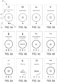
figures 3a, 3b, 3c, 3d, 4a, 4b, 4c, 4d, 5a, 5b, 5c, 5d show examples of configuration of a graphic user unit of the machine of the invention; -
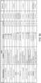
figures 6a ,6b are tables showing the configurations of a machine operating state display system; and -
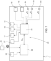
figure 7 is a block diagram of a control system of the machine offigure 1 . - With reference to
figures 1 and 2 ,number 1 indicates, as a whole, a coordinate measuring machine. - The
measuring machine 1 comprises a bed 2 and amovable unit 3 adapted to move a measuring sensor 16 (figure 2 ) in a measuring volume V. - The bed 2 conveniently consists of a granite slab with a rectangular shape and delimits the measuring volume V at the bottom.
- The
movable unit 3 comprises a main bridge-like carriage 5 movable on the bed 2 along a pair ofguides 6 parallel to a first horizontal axis Y parallel to the longer sides of the bed. Themain carriage 5 is provided with a pair ofuprights cross member 9 supported, at its ends, by theuprights guides 10 parallel to a second horizontal axis X orthogonal to the axis Y. - The
movable unit 3 further comprises asecond carriage 11 carried by thecross member 9 and movable along theguides 10 in a direction parallel to the axis X. Thesecond carriage 11 carries atower 12, which vertically extends upwards, is internally hollow and supports, on the inside, acolumn 13 movable along a vertical axis Z. Thecolumn 13 defines, with a lower end of its projecting downwards from thetower 12, aspindle 14 for the connection of ameasuring head 15 provided with a measuring probe, represented infigure 2 by themeasuring sensor 16. The measuring head shown herein is configured to orient themeasuring probe 16 relative to thespindle 14 according to two rotation axes, one perpendicular to the other. Advantageously, the measuring head and/or the measuring probe are configured to be interchangeably mounted on the machine so as to allow the machine to have a choice of different measuring heads and/or measuring probes in order to facilitate measuring operations, in particular when dealing with complex or delicate objects. The measuring probe can be of any type, with contact or contactless, for point-to-point measurements or for scans. - According to the invention, the
machine 1 comprises adisplay 17 located in a front zone of the machine and, preferably, in a lower front zone of thetower 12, a plurality ofstate LEDs 18 located in a top region of themachine 1, for example an upper zone of thetower 12, and a plurality ofspindle LEDs 19 located close to thespindle 14, as better described below. - According to the example shown herein, the
state LEDs 18 are conveniently configured in four strips, located on the four sides of thetower 12 close to a top end thereof. For example, the frontstate LED strips 18 can be vertical and the side ones can be horizontal, but other configurations are obviously possible. Thestate LEDs 18 are conveniently visible from a distance, i.e. from a distance of at least 10 m, preferably at least 20 m, at 360°. - The
state LEDs 18 can take on different colours and are adapted to provide a general indication of the operating state of the machine, so as to allow users to identify whether the operation is correct and/or whether the operator has to take some action. For example, thestate LEDs 18 can take on a red colour in case of alarm, a yellow colour in case of warning and a green or blue colour in case of regular operation. - Preferably, the
front state LEDs 18 gradually light up from the bottom to the top, for example on a scale from 1 to 10, indicating the percentage of speed at which the machine is working with respect to the maximum available speed. This is aimed at allowing a manager to verify that the machine is used as efficiently as possible and that unnecessary speed limitations are not maintained by mistake. - In the example shown herein, the
spindle LEDs 19 are conveniently configured in four horizontal strips, located on the four sides of thecolumn 13 close to thelower end 14 and are adapted to signal the state of the measuring head and of the measuring sensor. Thespindle LEDs 19 can take on different colours depending on the operating state, as well. TheLEDs 19 are conveniently visible from a medium distance, i.e. from a distance of at least 5 m, at 360°. - The
state LEDs 18 and thespindle LEDs 19 can also assume a fixed configuration, an on/off configuration or a breathing configuration with variable intensity in a continuous manner. - The
display 17 is configured so as to define a graphical user interface (GUI) 20 (figures 3-6 ) adapted to provide a more detailed description of the state of themachine 1. - The GUI 20 (
figure 3a ) can comprise astate indicator 21, for example a circular one, adapted to assume a colour corresponding to thestate LEDs 18, anotification panel 22 adapted to specifically describe the state of themachine 1 and aninformation panel 23 provided with a series of information pictograms 24, which can represent, for example, the presence or absence of software/firmware modules or notifications to be read. The size of theindicator 21 permits visibility to a remote operator, as opposed to the details represented by thenotification panel 22, which are visible by an operator standing close to the machine, i.e. at a distance of less than 2 metres. - Examples of alarm configurations of the
GUI 20, in which thestate indicator 21 is red, are shown infigures 3a,3b,3c,3d . The alarm configurations indicate critical conditions that prevent themachine 1 from correctly operating and require immediate intervention by an operator to restore operation. - Examples of warning configurations of the
GUI 20, in which thestate indicator 21 is yellow, are shown infigures 4a,4b,4c,4d . The warning configurations indicate abnormal but non-critical situations that require operators' attention. - Examples of information configurations of the
GUI 20, in which thestate indicator 21 is green and indicates normal operational conditions of the machine, are shown infigures 5a,5b,5c,5d . - The possible configurations of the
GUI 20 of thedisplay 17 and the corresponding configurations of thestate LEDs 18 and of thespindle LEDs 19 are shown in the table divided betweenfigures 6a and6b . - In particular, in a series of alarm configurations, the
state indicator 21 of theGUI 20, thestate LEDs 18 and, if turned on, thespindle LEDs 19 are red. - In each one of the aforesaid configurations, the
notification panel 22 provides an indication of the state of the machine, such as for example: - Ethernet connection lost;
- System failure;
- Motors are off;
- Air pressure high/low;
- Sensor crash;
- Machine crash;
- Rack crash (crash against the tool-holder rack);
- E-stop pressed (
emergency pushbutton 25 pressed, seefigure 7 ); - External E-stop activated (external emergency stop activated), in case the
machine 1 is part of an automatic line whose units are connected to one another through an automation hub 26 (figure 7 ), for example via Ethernet, and the emergency stop is caused by the stop of another unit of the line. - In a series of warning configurations, the
state indicator 21 of theGUI 20, thestate LEDs 18 and, if turned on, thespindle LEDs 19 are yellow; examples of the warning configurations are: - Ambient temperature low/high;
- Ambient temperature time gradient;
- Ambient temperature space gradient;
- Ambient temperature low/high;
- Sensor detached while on;
- Sensor out of range;
- Rack malfunction (malfunction of the tool holder);
- Sensor requires calibration;
- Please, turn motors on;
- System requires maintenance.
- In a series of configurations representative of a normal operation of the
machine 1, thestate indicator 21 of theGUI 20, thestate LEDs 18 and, if turned on, thespindle LEDs 19 are green; examples of these configurations are the following ones: - Sensor warming up;
- Booting (initializing the machine);
- Ready;
- Measuring (measurement in progress);
- Machine set to park position (machine parked in a position of interaction with the external automation).
- In a series of waiting configurations, the
state indicator 21 of theGUI 20, thestate LEDs 18 and, if turned on, thespindle LEDs 19 are blue; examples of the waiting configurations are: - System requires homing (the machine must be set to a predetermined rest position);
- Standby (the machine has been inactive for more than 5 minutes);
- Upgrading (software/firmware update);
- Calibrating (sensor calibration);
- Ready to exchange sensor.
- Obviously, this is an exemplary list of configurations, which could be modified, integrated or reduced depending on the needs.
- Furthermore, the disclosed configurations are not to be considered, as a whole, as a predetermined combination of features, but rather as a list of stand-alone features, which can be used singularly or in combination with one another.
-
Figure 7 shows a block diagram of acontrol system 29 of themachine 1, consisting of acentral control unit 30, conveniently integrated with in the bed 2, and of aperipheral control unit 31 carried by thetower 12. - The
central control unit 30 is responsible for the general control of themachine 1 and constitutes the interface of themachine 1 to the outside and, in particular, to anautomation hub 26 of the line; theperipheral control unit 31 is connected to thecentral control unit 30 and is configured to act as an interface between the latter and the devices/sensors carried by thecarriage 11, so as to rationalise and minimise the electrical wiring of themachine 1. - In particular, the
peripheral control unit 31 is connected to the measuringhead 15, to the measuringsensor 16 and to a plurality of sensors S1, S2, ..., Sn carried by thecarriage 11 or by thecolumn 12 including, for example, temperature probes. Theperipheral control unit 31 controls thedisplay 17, thestate LEDs 18 and thespindle LEDs 19 in response to input signals I1, 12, ..., In received from the sensors S1, S2, ..., Sn and to input signals Ic received from thecentral control unit 30. Acamera 27 is also connected to theperipheral control unit 31, conveniently fixed to a rear face of thecross member 9 and having the purpose of monitoring the measuring volume V. - In particular, the
control system 29, possibly by means of theperipheral control unit 31, is connected to a controller of the measuringhead 15 and/or of the measuring probe 16 (not shown) so as to be able to acquire the operational conditions of the measuring head and/or of the measuring probe. Thecontrol system 29 can be configured to control thedisplay 17 and the firststate light indicators 18 of the machine so as to allow said operational conditions to be displayed to an operator located in an adverse position, i.e. at a distance and/or behind the machine.
Claims (14)
- A coordinate measuring machine comprising a movable unit (3) adapted to move a measuring head (15) in a measuring volume (V), characterized by comprising an operating state display system comprising first state light indicators (18) arranged in a top portion (12) of the machine (1) and visible remotely from 360°, said first state light indicators (18) being configured to assume colours representative of different states of the machine (1), and a display (17) defining a graphical user interface (GUI) (20), the GUI (20) comprising at least one indicator (21) remotely visible and representative of the state of the machine (1) and an information area (22) visible by an operator in close proximity to the machine (1) and containing operational details related to the state of the machine (1).
- A machine as claimed in claim 1, comprising a control system (29) configured to acquire a current state of the machine and/or operational details related to a current state of the machine;
the control system being configured to control the display (17) and the first state light indicators (18) in such a manner as to display: the current state of the machine to an operator located at any position in proximity and at a distance around the machine, and operational details related to the current state of the machine to an operator located in proximity to the machine. - A machine as claimed in claim 1 or 2, wherein the movable unit (3) comprises a first carriage (5) movable along a first axis (Y), a second carriage (11) carried by the first carriage (5) and movable with respect thereto along a second axis (X) orthogonal to the first axis (Y), and a spindle (14) carried by the second carriage (11), movable with respect thereto along a third axis (Z) orthogonal to the first and second axes (Y, X) and adapted to support the measuring head (15).
- A machine as claimed in claim 3, further comprising at least a second indicator light (19) located on the spindle (14) or on the measuring head (15) and operable in response to operating conditions of the measuring head (15).
- A machine as claimed in claim 4, wherein the control system (29) is configured to acquire the operating conditions of the measuring head and to control the display (17) and the first state light indicators (18) in such a way that said operating conditions of the measuring head can be displayed to an operator located at any remote location around the machine; preferably the measuring head is configured to orient a measuring probe relative to the moving unit according to at least one axis of rotation; preferably the measuring head and/or the measuring probe are configured to be automatically or semi-automatically interchangeable from the machine.
- Machine as claimed in claim 5, wherein the second light indicator (19), when on, and the GUI indicator (21) are the same colour as the first state light indicators (18) .
- Machine as claimed in claim 6, wherein the first state light indicators (18), the second light indicator (19), and the GUI indicator (21) (20) are configured to take on at least a first colour corresponding to an alarm indication, a second colour corresponding to a warning indication, and a third colour corresponding to a normal operation indication.
- A machine as claimed in claim 7, wherein the alarm indication is generated in response to the detection of one or more conditions selected from the group comprising: loss of the Ethernet connection, system failure, motors off, air pressure not within a predetermined range, impact of the machine, measuring head or spindle, impact against the tool rack, emergency stop by pushbutton or by external signal from a connected machine.
- Machine as claimed in claim 7 or 8, wherein the warning indication is generated in response to the detection of one or more conditions selected from the group comprising: ambient temperature not within a predetermined range of values, spatial gradient of ambient temperature not within a predetermined range of values, temporal gradient of ambient temperature not within a predetermined range of values, workpiece temperature not within a predetermined range of values, measuring sensor disconnected without turning it off, measuring sensor outside a predetermined range of operation, malfunction of the tool magazine, need for machine calibration, need to turn on motors, need for maintenance.
- A machine as claimed in any of claims 7 to 9, wherein the indication of normal operation is generated in response to the detection of one or more conditions selected from the group comprising: sensor warm-up, machine initialization, machine ready, measurement in progress, machine arranged in parking position.
- A machine as claimed in any one of claims 7 to 10, wherein the first light indicators (18), the second light indicator (19), and the GUI indicator (21) are configured to assume a corresponding fourth colour in response to the detection of one or more conditions selected from the group comprising: need to arrange the machine in a rest position, idle machine, software/firmware update, sensor calibration, machine ready for sensor change.
- Machine as claimed in any of claims 4 to 11 when dependent on claims 2 and 3 , wherein the control system (29) comprises a central control unit (30) stationary with respect to the measurement volume (V) and a peripheral control unit (31) carried by the second carriage (11) and connected to the central control unit (30), the peripheral control unit (31) being connected to the display (17), the first state light indicators (18) and the second light indicator (19) to control them in response to signals (I1, I2, ... , In) received from respective sensors carried by the carriage (11) and to signals (Ic) received from the central control unit (30).
- Machine as claimed in claim 12, wherein the central control unit (30) is configured to be connected with an automation hub (26) of an automated line of which the machine is a part.
- A machine as claimed in any of claims 3 to 13 when dependent on claim 2, characterized by being a bridge-type machine, and that the top portion of the machine (1) is a tower (12) carried by the second carriage (11) and housing a column (13) vertically movable and defining said spindle (14) .
Applications Claiming Priority (1)
| Application Number | Priority Date | Filing Date | Title |
|---|---|---|---|
| IT102023000020241A IT202300020241A1 (en) | 2023-10-02 | 2023-10-02 | COORDINATE MEASURING MACHINE WITH OPERATIONAL STATUS DISPLAY SYSTEM |
Publications (1)
| Publication Number | Publication Date |
|---|---|
| EP4534949A1 true EP4534949A1 (en) | 2025-04-09 |
Family
ID=89321614
Family Applications (1)
| Application Number | Title | Priority Date | Filing Date |
|---|---|---|---|
| EP24203333.0A Pending EP4534949A1 (en) | 2023-10-02 | 2024-09-27 | Coordinate measuring machine with operation state display system |
Country Status (4)
| Country | Link |
|---|---|
| US (1) | US20250109938A1 (en) |
| EP (1) | EP4534949A1 (en) |
| CN (1) | CN119756256A (en) |
| IT (1) | IT202300020241A1 (en) |
Citations (7)
| Publication number | Priority date | Publication date | Assignee | Title |
|---|---|---|---|---|
| EP0694158B1 (en) | 1993-04-16 | 1999-05-26 | BROWN & SHARPE MANUFACTURING COMPANY | Control axis mounted computer interface for coordinate measuring machines |
| CN203759489U (en) * | 2014-03-04 | 2014-08-06 | 北京南航立科机械有限公司 | Lamp belt type numerical control system state display device |
| DE102014220540A1 (en) * | 2013-10-11 | 2015-04-16 | Carl Zeiss Industrielle Messtechnik Gmbh | Coordinate measuring machine with operating device for an operator and method for operating the coordinate measuring machine |
| JP2019090821A (en) * | 2019-01-18 | 2019-06-13 | 株式会社東京精密 | Three-dimensional measuring instrument |
| JP2020041988A (en) * | 2018-09-13 | 2020-03-19 | 株式会社東京精密 | Abnormality detection method and three-dimensional measuring machine |
| US20200356218A1 (en) * | 2019-05-07 | 2020-11-12 | Hexagon Metrology, Inc. | Automated inspection process for batch production |
| US20230184531A1 (en) * | 2021-12-10 | 2023-06-15 | Hexagon Metrology Gmbh | Coordinate Measuring Apparatus |
-
2023
- 2023-10-02 IT IT102023000020241A patent/IT202300020241A1/en unknown
-
2024
- 2024-09-27 EP EP24203333.0A patent/EP4534949A1/en active Pending
- 2024-10-01 US US18/904,063 patent/US20250109938A1/en active Pending
- 2024-10-08 CN CN202411394115.3A patent/CN119756256A/en active Pending
Patent Citations (7)
| Publication number | Priority date | Publication date | Assignee | Title |
|---|---|---|---|---|
| EP0694158B1 (en) | 1993-04-16 | 1999-05-26 | BROWN & SHARPE MANUFACTURING COMPANY | Control axis mounted computer interface for coordinate measuring machines |
| DE102014220540A1 (en) * | 2013-10-11 | 2015-04-16 | Carl Zeiss Industrielle Messtechnik Gmbh | Coordinate measuring machine with operating device for an operator and method for operating the coordinate measuring machine |
| CN203759489U (en) * | 2014-03-04 | 2014-08-06 | 北京南航立科机械有限公司 | Lamp belt type numerical control system state display device |
| JP2020041988A (en) * | 2018-09-13 | 2020-03-19 | 株式会社東京精密 | Abnormality detection method and three-dimensional measuring machine |
| JP2019090821A (en) * | 2019-01-18 | 2019-06-13 | 株式会社東京精密 | Three-dimensional measuring instrument |
| US20200356218A1 (en) * | 2019-05-07 | 2020-11-12 | Hexagon Metrology, Inc. | Automated inspection process for batch production |
| US20230184531A1 (en) * | 2021-12-10 | 2023-06-15 | Hexagon Metrology Gmbh | Coordinate Measuring Apparatus |
Also Published As
| Publication number | Publication date |
|---|---|
| US20250109938A1 (en) | 2025-04-03 |
| IT202300020241A1 (en) | 2025-04-02 |
| CN119756256A (en) | 2025-04-04 |
Similar Documents
| Publication | Publication Date | Title |
|---|---|---|
| JP5424686B2 (en) | Circuit board work system | |
| CN202129605U (en) | Numerical control press-fit machine | |
| JP5823848B2 (en) | Processing machine | |
| EP3505898B1 (en) | Liquid leakage detection system and liquid leakage detection method | |
| CN107209489B (en) | Unmanned aerial vehicle and its state monitoring method, state monitoring system, and state monitoring device | |
| US20250109938A1 (en) | Coordinate measuring machine with operation state display system | |
| CN109926727A (en) | Nameplate laser automatic marking machine | |
| JP6185011B2 (en) | Injection molding system | |
| CN106092033A (en) | Flatness automatic detection device | |
| CN105563198B (en) | A kind of integrated form may move disc type tool magazine and manipulator detection device for combination property | |
| KR20170070643A (en) | Management apparatus and method for managing facility | |
| US5177469A (en) | Safety device for an IC handler and method for its operation | |
| JP2020034516A (en) | Length measuring device, method for measuring length, program, and stadiometer | |
| JP2015108487A (en) | Air conditioner and data suction device | |
| CN113406424B (en) | Aging test system and method | |
| JP6279360B2 (en) | Shape measuring instruments | |
| CN110586497A (en) | High-precision multi-sensor size detection device and data acquisition and processing system thereof | |
| JP5433848B2 (en) | Image measuring device | |
| EP3786572B1 (en) | One-dimensional measuring machine with means for indicating a chosen origin | |
| JPH0430799B2 (en) | ||
| JP4953859B2 (en) | Multi-optical axis photoelectric sensor system, multi-optical axis photoelectric sensor, abnormality identification device, abnormality identification method, and storage medium | |
| CN214655570U (en) | Computerized flat knitting machine control device | |
| CN113467380A (en) | Numerical controller | |
| KR101789020B1 (en) | Touch type control apparatus for tool magazine of machine tool and method thereof | |
| CN209850689U (en) | Detection skiving device |
Legal Events
| Date | Code | Title | Description |
|---|---|---|---|
| PUAI | Public reference made under article 153(3) epc to a published international application that has entered the european phase |
Free format text: ORIGINAL CODE: 0009012 |
|
| STAA | Information on the status of an ep patent application or granted ep patent |
Free format text: STATUS: THE APPLICATION HAS BEEN PUBLISHED |
|
| AK | Designated contracting states |
Kind code of ref document: A1 Designated state(s): AL AT BE BG CH CY CZ DE DK EE ES FI FR GB GR HR HU IE IS IT LI LT LU LV MC ME MK MT NL NO PL PT RO RS SE SI SK SM TR |
|
| STAA | Information on the status of an ep patent application or granted ep patent |
Free format text: STATUS: REQUEST FOR EXAMINATION WAS MADE |
|
| 17P | Request for examination filed |
Effective date: 20251009 |
|
| RAP1 | Party data changed (applicant data changed or rights of an application transferred) |
Owner name: HEXAGON INNOVATION HUB GMBH |