EP4534910A1 - Support pin for igniter assembly - Google Patents
Support pin for igniter assembly Download PDFInfo
- Publication number
- EP4534910A1 EP4534910A1 EP24204833.8A EP24204833A EP4534910A1 EP 4534910 A1 EP4534910 A1 EP 4534910A1 EP 24204833 A EP24204833 A EP 24204833A EP 4534910 A1 EP4534910 A1 EP 4534910A1
- Authority
- EP
- European Patent Office
- Prior art keywords
- support pin
- igniter
- section
- pin holes
- tip
- Prior art date
- Legal status (The legal status is an assumption and is not a legal conclusion. Google has not performed a legal analysis and makes no representation as to the accuracy of the status listed.)
- Granted
Links
Images


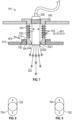
Classifications
-
- F—MECHANICAL ENGINEERING; LIGHTING; HEATING; WEAPONS; BLASTING
- F23—COMBUSTION APPARATUS; COMBUSTION PROCESSES
- F23R—GENERATING COMBUSTION PRODUCTS OF HIGH PRESSURE OR HIGH VELOCITY, e.g. GAS-TURBINE COMBUSTION CHAMBERS
- F23R3/00—Continuous combustion chambers using liquid or gaseous fuel
- F23R3/42—Continuous combustion chambers using liquid or gaseous fuel characterised by the arrangement or form of the flame tubes or combustion chambers
- F23R3/60—Support structures; Attaching or mounting means
-
- F—MECHANICAL ENGINEERING; LIGHTING; HEATING; WEAPONS; BLASTING
- F02—COMBUSTION ENGINES; HOT-GAS OR COMBUSTION-PRODUCT ENGINE PLANTS
- F02C—GAS-TURBINE PLANTS; AIR INTAKES FOR JET-PROPULSION PLANTS; CONTROLLING FUEL SUPPLY IN AIR-BREATHING JET-PROPULSION PLANTS
- F02C7/00—Features, components parts, details or accessories, not provided for in, or of interest apart form groups F02C1/00 - F02C6/00; Air intakes for jet-propulsion plants
- F02C7/26—Starting; Ignition
- F02C7/264—Ignition
- F02C7/266—Electric
-
- F—MECHANICAL ENGINEERING; LIGHTING; HEATING; WEAPONS; BLASTING
- F23—COMBUSTION APPARATUS; COMBUSTION PROCESSES
- F23R—GENERATING COMBUSTION PRODUCTS OF HIGH PRESSURE OR HIGH VELOCITY, e.g. GAS-TURBINE COMBUSTION CHAMBERS
- F23R3/00—Continuous combustion chambers using liquid or gaseous fuel
- F23R3/002—Wall structures
-
- F—MECHANICAL ENGINEERING; LIGHTING; HEATING; WEAPONS; BLASTING
- F23—COMBUSTION APPARATUS; COMBUSTION PROCESSES
- F23R—GENERATING COMBUSTION PRODUCTS OF HIGH PRESSURE OR HIGH VELOCITY, e.g. GAS-TURBINE COMBUSTION CHAMBERS
- F23R3/00—Continuous combustion chambers using liquid or gaseous fuel
- F23R3/005—Combined with pressure or heat exchangers
-
- H—ELECTRICITY
- H01—ELECTRIC ELEMENTS
- H01T—SPARK GAPS; OVERVOLTAGE ARRESTERS USING SPARK GAPS; SPARKING PLUGS; CORONA DEVICES; GENERATING IONS TO BE INTRODUCED INTO NON-ENCLOSED GASES
- H01T13/00—Sparking plugs
- H01T13/02—Details
- H01T13/06—Covers forming a part of the plug and protecting it against adverse environment
-
- H—ELECTRICITY
- H01—ELECTRIC ELEMENTS
- H01T—SPARK GAPS; OVERVOLTAGE ARRESTERS USING SPARK GAPS; SPARKING PLUGS; CORONA DEVICES; GENERATING IONS TO BE INTRODUCED INTO NON-ENCLOSED GASES
- H01T13/00—Sparking plugs
- H01T13/02—Details
- H01T13/08—Mounting, fixing or sealing of sparking plugs, e.g. in combustion chamber
-
- H—ELECTRICITY
- H01—ELECTRIC ELEMENTS
- H01T—SPARK GAPS; OVERVOLTAGE ARRESTERS USING SPARK GAPS; SPARKING PLUGS; CORONA DEVICES; GENERATING IONS TO BE INTRODUCED INTO NON-ENCLOSED GASES
- H01T13/00—Sparking plugs
- H01T13/02—Details
- H01T13/16—Means for dissipating heat
-
- F—MECHANICAL ENGINEERING; LIGHTING; HEATING; WEAPONS; BLASTING
- F23—COMBUSTION APPARATUS; COMBUSTION PROCESSES
- F23R—GENERATING COMBUSTION PRODUCTS OF HIGH PRESSURE OR HIGH VELOCITY, e.g. GAS-TURBINE COMBUSTION CHAMBERS
- F23R2900/00—Special features of, or arrangements for continuous combustion chambers; Combustion processes therefor
- F23R2900/03044—Impingement cooled combustion chamber walls or subassemblies
Definitions
- the present invention relates to gas turbine engines and, in particular, to a support pin for an igniter assembly of a cooling basket of a gas turbine engine.
- a support pin of a combustor assembly includes a casing of a combustor and an igniter.
- the igniter includes a main section and a tip from which sparks generated by the igniter within the main section are ejected.
- the support pin includes an exterior section, a main body and a tip section.
- the exterior section is connectable to the casing.
- the igniter is affixable to the exterior section.
- the main body is integrally formed with the exterior section and is disposable to surround the main section of the igniter.
- the main body has a first wall thickness and defines support pin holes.
- the tip section is integrally formed with the main body and is disposable to surround the tip of the igniter.
- the tip section has a second wall thickness. The second wall thickness exceeds the first wall thickness.
- This aspect may extend to an assembly comprising the support pin and the combustor assembly.
- the support pin holes are disposed in an array surrounding the igniter.
- At least one or more of the support pin holes includes at least one of a venturi element and a turbulator.
- the main body defines first support pin holes and the tip section defines second support pin holes.
- a combustor assembly includes a combustor wall defining an interior, a casing disposed about the combustor wall to define a space for air flow, an igniter to generate sparks to initiate combustion within the interior and a support pin connected to the casing and configured to support the igniter to extend through the space.
- the support pin defines support pin holes through which the air flow passes to impinge upon the igniter.
- the air flow is drawn from compressed air supplied for the combustion.
- the igniter includes electrical elements configured to generate the sparks and an igniter body.
- the igniter includes a main section surrounding the electrical elements and defining through-holes by which the air flow, having passed through the support pin holes, enters an igniter interior, and a tip coplanar with the combustor wall and facing the interior from which the sparks are ejected.
- the support pin includes a main body surrounding the main section of the igniter body, the main body having a first wall thickness and defining the support pin holes, and a tip section surrounding the tip of the igniter body and having a second wall thickness exceeding the first wall thickness.
- the combustor wall and the casing define first and second apertures, respectively, and the support pin is connected to the casing at the second aperture and is configured to support the igniter between the first and second apertures.
- the support pin holes are disposed in an array surrounding the igniter.
- At least one or more of the support pin holes includes at least one of a venturi element and a turbulator.
- a combustor assembly includes a combustor wall defining an interior and including a flange defining flange openings, a casing disposed about the combustor wall to define a space for air flow, an igniter to generate sparks to initiate combustion within the interior, the igniter including a main section and a tip from which the sparks are ejected, and a support pin connected to the casing and configured to support the igniter to extend through the space.
- the second support pin holes corresponding to the flange openings may include each of the second support pin holes corresponding in position to a corresponding one of the flange openings.
- the igniter includes electrical elements configured to generate the sparks and an igniter body comprising the main section and the tip.
- the main section surrounds the electrical elements and defines through-holes by which the air flow, having passed through the first support pin holes, enters an igniter interior.
- the tip is coplanar with the combustor wall and faces the interior.
- the support pin includes a main body surrounding the main section of the igniter body, the main body having a first wall thickness and defining the first support pin holes, and a tip section surrounding the tip of the igniter body, the tip section having a second wall thickness exceeding the first wall thickness and defining the second support pin holes.
- the combustor wall and the casing define first and second apertures, respectively, and the support pin is connected to the casing at the second aperture and is configured to support the igniter between the first and second apertures.
- the first support pin holes are disposed in an array surrounding the igniter.
- At least one or more of the first support pin holes includes at least one of a venturi element and a turbulator.
- the flange openings are round (e.g. having a circular or substantially circular cross-section) and the second support pin holes are slots.
- the flange openings are slots and the second support pin holes are round (e.g. having a circular or substantially circular cross-section).
- gas turbine engine including, but not limited to, turbofans, turboshafts, turboprops, turbojets, etc.
- gas turbine engine described below is provided by way of example, and should not be interpreted as limiting the scope of the application or the claims in any way.
- FIG. 1 schematically illustrates a gas turbine engine 20.
- the gas turbine engine 20 is disclosed herein as a two-spool turbofan that generally incorporates a fan section 22, a compressor section 24, a combustor section 26 and a turbine section 28.
- Alternative engines might include other systems or features.
- the fan section 22 drives air along a bypass flow path B in a bypass duct, while the compressor section 24 drives air along a core flow path C for compression and communication into the combustor section 26 then expansion through the turbine section 28.
- FIG. 1 schematically illustrates a gas turbine engine 20.
- the gas turbine engine 20 is disclosed herein as a two-spool turbofan that generally incorporates a fan section 22, a compressor section 24, a combustor section 26 and a turbine section 28.
- Alternative engines might include other systems or features.
- the fan section 22 drives air along a bypass flow path B in a bypass duct
- the compressor section 24 drives air along a core flow path C for compression and communication into the combustor section 26
- the exemplary engine 20 generally includes a low speed spool 30 and a high speed spool 32 mounted for rotation about an engine central longitudinal axis A relative to an engine static structure 36 via several bearing systems 38. It should be understood that various bearing systems 38 at various locations may alternatively or additionally be provided, and the location of bearing systems 38 may be varied as appropriate to the application.
- the low speed spool 30 generally includes an inner shaft 40 that interconnects a fan 42, a low pressure compressor 44 and a low pressure turbine 46.
- the inner shaft 40 is connected to the fan 42 through a speed change mechanism, which in exemplary gas turbine engine 20 is illustrated as a geared architecture 48 to drive the fan 42 at a lower speed than the low speed spool 30.
- the high speed spool 32 includes an outer shaft 50 that interconnects a high pressure compressor 52 and high pressure turbine 54.
- a combustor 56 is arranged in exemplary gas turbine 20 between the high pressure compressor 52 and the high pressure turbine 54.
- An engine static structure 36 is arranged generally between the high pressure turbine 54 and the low pressure turbine 46.
- the engine static structure 36 further supports bearing systems 38 in the turbine section 28.
- the inner shaft 40 and the outer shaft 50 are concentric and rotate via bearing systems 38 about the engine central longitudinal axis A which is collinear with their longitudinal axes.
- each of the positions of the fan section 22, compressor section 24, combustor section 26, turbine section 28, and fan drive gear system 48 may be varied.
- gear system 48 may be located aft of combustor section 26 or even aft of turbine section 28, and fan section 22 may be positioned forward or aft of the location of gear system 48.
- the combustor section 26 typically includes a combustor wall, which is formed to define an interior in which combustion occurs, a casing that surrounds an exterior of the combustor wall and igniters.
- the igniters generate sparks that initiate combustion within the interior.
- the igniters are often subject to significant and constant heat loading while having to house sensitive electrical components for spark generation. This heat loading is increasing as combustion gas temperatures are increasing even while spare cooling air is becoming increasingly scarce. Heat loading is also increasing due to other factors including, but not limited to, high speed flows and special combustion conditions, such as fuel impingement.
- a combustor assembly 201 includes a combustor wall 210 defining an interior 211 in which combustion occurs and a first aperture 212, a casing 220, an igniter 230 and a support pin 240.
- the combustor wall 210 includes a flange 213 at and around the first aperture 212.
- the casing 220 is disposed about the combustor wall 210 at a distance D to define a space 221 for air flow AF between an exterior surface 211 of the combustor wall 210 and an interior surface 222 of the casing 220.
- the air flow AF can include or be provided as a cooling air flow which is drawn from compressed air supplied to the interior 211 from a compressor, such as compressor section 24 of the gas turbine engine 20 of FIG. 1 .
- the casing 220 is configured to maintain a pressure for the combustion inside the combustor wall 210 and defines a second aperture 223.
- the igniter 230 includes electrical elements 231 that are configured to generate sparks to initiate combustion within the interior 211 and an igniter body 232.
- the support pin 240 is connected to the casing 220 and is configured to support the igniter 230 such that the igniter 230 extends longitudinally along longitudinal axis LA through the space 221 and between the first aperture 212 and the second aperture 223.
- the support pin 240 defines support pin holes 241 through which the air flow AF passed to impinge upon an exterior of the igniter body 232 of the igniter 230.
- the support pin holes 241 cooperatively form a cooling basket 250.
- the impingement of the air flow AF on the exterior of the igniter body 232 of the igniter 230 provides additional cooling to the igniter 230 without the cost of drawing additional air from the space 221 and without air from any other source. This, in turn, allows the combustor assembly 201 to be operated at increased power and correspondingly increased temperatures without risking damage to the igniter 230 and without requiring that the igniter 230 be redesigned or otherwise provided with materials that are able to withstand elevated temperatures.
- the igniter body 232 includes a main section 2321 and a tip 2322.
- the main section 2321 surrounds the electrical elements 231 and defines through-holes 2323 by which the air flow AF, having passed through the support pin holes 241, enters an interior of the igniter 230 to further cool the electrical elements 231.
- the tip 2322 can be, but is not required to be, generally coplanar with the combustor wall 210 and faces the interior 211.
- the sparks generated by the electrical elements 231 of the igniter 230 are ejected into the interior 211 from the tip 2322.
- the support pin 240 can include an exterior section 242, a main body 243 and a tip section 244.
- the exterior section 242 is connectable to the casing 220 at the second aperture 223.
- the igniter 230 can be affixable to the exterior section 242 by threading, for example, or by other suitable features.
- the main body 243 is integrally formed with the exterior section 242 and is disposable to surround the main section 2321 of the igniter body 232.
- the main body 243 has a first wall thickness T1 and defines the support pin holes 241.
- the tip section 244 is disposable to surround the tip 2322 of the igniter body 232 at the first aperture 212 and has a second wall thickness T2.
- the second wall thickness T2 exceeds the first wall thickness T1.
- the support pin holes 241 are disposed in an array 301 surrounding the igniter 230.
- the array 301 can be provided as a lattice array with rows and columns of support pin holes 241.
- the array 301 is illustrated in FIG. 3B as being a non-staggered array, it is to be understood that other embodiments are possible including, but not limited to, embodiments in which the array 301 is a staggered array.
- one or more of the support pin holes 241 can be provided as a slot 401.
- At least one or more of the support pin holes 241 can include at least one of a venturi element 501 (see FIG. 5 ) to locally increase a velocity of the air flow AF and a turbulator 601 (see FIG. 6 ) to locally increase a turbulence of the air flow AF.
- a combustor assembly 701 is provided.
- the combustor assembly 701 is generally similar to the combustor assembly 201 of FIG. 2 (and of FIGS. 3-6 ) and thus will not be described in detail except as combustor assembly 701 differs from combustor assembly 201.
- the combustor wall 210 includes the flange 213 and the flange 213 defines flange openings 702.
- the main body 243 of the support pin 240 defines first support pin holes 703 through which a first portion of the air flow AF1 passes to impinge upon the main section 2321 of the igniter body 232 of the igniter 230 and the tip section 244 of the support pin 240 defines second support pin holes 704.
- Each of the second support pin holes 704 corresponds in position to a corresponding one of the flange openings 702.
- a second portion of the air flow AF2, having passed through the flange openings 702 passes through the second support pin holes 704 to impinge upon the tip 2322 of the igniter body 232 of the igniter 230.
- the flange openings 702 can be round and the second support pin holes 704 can be slots (see FIG. 8 ) or, in the alternative, the flange openings 702 can be slots and the second support pin holes 704 can be round (see FIG. 9 ). In either case, differential thermal expansion between the combustor wall 210 and the support pin 240 can be absorbed and accounted for by the varied shapes of the flange openings 702 and the second support pin holes 704.
Landscapes
- Engineering & Computer Science (AREA)
- Chemical & Material Sciences (AREA)
- Combustion & Propulsion (AREA)
- Mechanical Engineering (AREA)
- General Engineering & Computer Science (AREA)
- Turbine Rotor Nozzle Sealing (AREA)
- Gas Burners (AREA)
Abstract
Description
- The present invention relates to gas turbine engines and, in particular, to a support pin for an igniter assembly of a cooling basket of a gas turbine engine.
- In a gas turbine engine, fuel and compressed air are combusted in a combustor to produce a high-temperature and high-pressure fluid. This fluid enters a turbine and interacts with rows or stages of turbine blades and vanes. The interaction between the high-temperature and high-pressure fluid with the turbine blades and vanes causes the stages of turbine blades to rotate a rotor. The rotor rotation drives a compressor to compress the air for the combustor and, as noted above, can be used to drive operations of a generator to produce electricity and/or for propulsion.
- According to an aspect of the present invention, a support pin of a combustor assembly is provided. The combustor assembly includes a casing of a combustor and an igniter. The igniter includes a main section and a tip from which sparks generated by the igniter within the main section are ejected. The support pin includes an exterior section, a main body and a tip section. The exterior section is connectable to the casing. The igniter is affixable to the exterior section. The main body is integrally formed with the exterior section and is disposable to surround the main section of the igniter. The main body has a first wall thickness and defines support pin holes. The tip section is integrally formed with the main body and is disposable to surround the tip of the igniter. The tip section has a second wall thickness. The second wall thickness exceeds the first wall thickness.
- This aspect may extend to an assembly comprising the support pin and the combustor assembly.
- Optionally, and in accordance with the above, the support pin holes are disposed in an array surrounding the igniter.
- Optionally, and in accordance with any of the above, at least one or more of the support pin holes includes at least one of a venturi element and a turbulator.
- Optionally, and in accordance with any of the above, the main body defines first support pin holes and the tip section defines second support pin holes.
- According to another aspect of the present invention, a combustor assembly is provided and includes a combustor wall defining an interior, a casing disposed about the combustor wall to define a space for air flow, an igniter to generate sparks to initiate combustion within the interior and a support pin connected to the casing and configured to support the igniter to extend through the space. The support pin defines support pin holes through which the air flow passes to impinge upon the igniter.
- Optionally, and in accordance with any of the above, the air flow is drawn from compressed air supplied for the combustion.
- Optionally, and in accordance with any of the above, the igniter includes electrical elements configured to generate the sparks and an igniter body. The igniter includes a main section surrounding the electrical elements and defining through-holes by which the air flow, having passed through the support pin holes, enters an igniter interior, and a tip coplanar with the combustor wall and facing the interior from which the sparks are ejected.
- Optionally, and in accordance with any of the above, the support pin includes a main body surrounding the main section of the igniter body, the main body having a first wall thickness and defining the support pin holes, and a tip section surrounding the tip of the igniter body and having a second wall thickness exceeding the first wall thickness.
- Optionally, and in accordance with any of the above, the combustor wall and the casing define first and second apertures, respectively, and the support pin is connected to the casing at the second aperture and is configured to support the igniter between the first and second apertures.
- Optionally, and in accordance with any of the above, the support pin holes are disposed in an array surrounding the igniter.
- Optionally, and in accordance with any of the above, at least one or more of the support pin holes includes at least one of a venturi element and a turbulator.
- According to another aspect of the present invention, a combustor assembly is provided and includes a combustor wall defining an interior and including a flange defining flange openings, a casing disposed about the combustor wall to define a space for air flow, an igniter to generate sparks to initiate combustion within the interior, the igniter including a main section and a tip from which the sparks are ejected, and a support pin connected to the casing and configured to support the igniter to extend through the space. The support pin defines first support pin holes through which a first portion of the air flow passes to impinge upon the main section and second support pin holes corresponding to the flange openings and through which a second portion of the air flow, having passed through the flange openings, passes to impinge upon the tip.
- The second support pin holes corresponding to the flange openings may include each of the second support pin holes corresponding in position to a corresponding one of the flange openings.
- Optionally, and in accordance with any of the above, the air flow is drawn from compressed air supplied for the combustion.
- Optionally, and in accordance with any of the above, the igniter includes electrical elements configured to generate the sparks and an igniter body comprising the main section and the tip. The main section surrounds the electrical elements and defines through-holes by which the air flow, having passed through the first support pin holes, enters an igniter interior. The tip is coplanar with the combustor wall and faces the interior.
- Optionally, and in accordance with any of the above, the support pin includes a main body surrounding the main section of the igniter body, the main body having a first wall thickness and defining the first support pin holes, and a tip section surrounding the tip of the igniter body, the tip section having a second wall thickness exceeding the first wall thickness and defining the second support pin holes.
- Optionally, and in accordance with any of the above, the combustor wall and the casing define first and second apertures, respectively, and the support pin is connected to the casing at the second aperture and is configured to support the igniter between the first and second apertures.
- Optionally, and in accordance with any of the above, the first support pin holes are disposed in an array surrounding the igniter.
- Optionally, and in accordance with any of the above, at least one or more of the first support pin holes includes at least one of a venturi element and a turbulator.
- Optionally, and in accordance with any of the above, the flange openings are round (e.g. having a circular or substantially circular cross-section) and the second support pin holes are slots.
- Optionally, and in accordance with any of the above, the flange openings are slots and the second support pin holes are round (e.g. having a circular or substantially circular cross-section).
- Additional features and advantages are realized through the techniques of the present disclosure. Other embodiments and aspects of the disclosure are described in detail herein and are considered a part of the claimed technical concept. For a better understanding of the disclosure with the advantages and the features, refer to the description and to the drawings.
- For a more complete understanding of this disclosure, reference is now made to the following brief description, taken in connection with the accompanying drawings and detailed description, wherein like reference numerals represent like parts:
-
FIG. 1 is a partial cross-sectional view of a portion of an exemplary gas turbine engine in accordance with embodiments; -
FIG. 2 is a side view of a combustor assembly in accordance with embodiments; -
FIG. 3A is an axial view of a support pin and an igniter of the combustor assembly ofFIG. 2 taken along line 2-2 in accordance with embodiments; -
FIG. 3B is a plan view of support pin holes of the support pin ofFIGS. 2 and3A in an array in accordance with embodiments; -
FIG. 4 is a plan view of support pin holes of the support pin ofFIGS. 2 and3A with slot shapes in accordance with embodiments; -
FIG. 5 is a side schematic view of a support pin hole with a venturi element in accordance with embodiments; -
FIG. 6 is a side schematic view of a support pin hole with turbulators in accordance with embodiments; -
FIG. 7 is a side view of a combustor assembly with first and second support pin holes in accordance with embodiments; -
FIG. 8 is a schematic illustration of round flange openings and slotted support pin holes in accordance with embodiments; and -
FIG. 9 is a schematic illustration of slotted flange openings and round support pin holes in accordance with embodiments. - The following disclosure is applicable to any type of gas turbine engine, including, but not limited to, turbofans, turboshafts, turboprops, turbojets, etc. The gas turbine engine described below is provided by way of example, and should not be interpreted as limiting the scope of the application or the claims in any way.
-
FIG. 1 schematically illustrates agas turbine engine 20. Thegas turbine engine 20 is disclosed herein as a two-spool turbofan that generally incorporates a fan section 22, acompressor section 24, acombustor section 26 and aturbine section 28. Alternative engines might include other systems or features. The fan section 22 drives air along a bypass flow path B in a bypass duct, while thecompressor section 24 drives air along a core flow path C for compression and communication into thecombustor section 26 then expansion through theturbine section 28. Although depicted as a two-spool turbofan gas turbine engine in the disclosed non-limiting embodiment, it should be understood that the concepts described herein are not limited to use with two-spool turbofans as the teachings may be applied to other types of turbine engines including three-spool architectures. - The
exemplary engine 20 generally includes alow speed spool 30 and ahigh speed spool 32 mounted for rotation about an engine central longitudinal axis A relative to an enginestatic structure 36 viaseveral bearing systems 38. It should be understood that various bearingsystems 38 at various locations may alternatively or additionally be provided, and the location of bearingsystems 38 may be varied as appropriate to the application. - The
low speed spool 30 generally includes aninner shaft 40 that interconnects afan 42, alow pressure compressor 44 and alow pressure turbine 46. Theinner shaft 40 is connected to thefan 42 through a speed change mechanism, which in exemplarygas turbine engine 20 is illustrated as a gearedarchitecture 48 to drive thefan 42 at a lower speed than thelow speed spool 30. Thehigh speed spool 32 includes anouter shaft 50 that interconnects ahigh pressure compressor 52 andhigh pressure turbine 54. Acombustor 56 is arranged inexemplary gas turbine 20 between thehigh pressure compressor 52 and thehigh pressure turbine 54. An enginestatic structure 36 is arranged generally between thehigh pressure turbine 54 and thelow pressure turbine 46. The enginestatic structure 36 furthersupports bearing systems 38 in theturbine section 28. Theinner shaft 40 and theouter shaft 50 are concentric and rotate via bearingsystems 38 about the engine central longitudinal axis A which is collinear with their longitudinal axes. - The core airflow is compressed by the
low pressure compressor 44 then thehigh pressure compressor 52, mixed and burned with fuel in thecombustor 56, then expanded over thehigh pressure turbine 54 andlow pressure turbine 46. Theturbines low speed spool 30 andhigh speed spool 32 in response to the expansion. It will be appreciated that each of the positions of the fan section 22,compressor section 24,combustor section 26,turbine section 28, and fandrive gear system 48 may be varied. For example,gear system 48 may be located aft ofcombustor section 26 or even aft ofturbine section 28, and fan section 22 may be positioned forward or aft of the location ofgear system 48. - The
combustor section 26 typically includes a combustor wall, which is formed to define an interior in which combustion occurs, a casing that surrounds an exterior of the combustor wall and igniters. The igniters generate sparks that initiate combustion within the interior. As such, the igniters are often subject to significant and constant heat loading while having to house sensitive electrical components for spark generation. This heat loading is increasing as combustion gas temperatures are increasing even while spare cooling air is becoming increasingly scarce. Heat loading is also increasing due to other factors including, but not limited to, high speed flows and special combustion conditions, such as fuel impingement. - A need therefore exists for a system to increase cooling of the igniters of a combustion system.
- Thus, as will be described below, a cooling basket support pin design is provided for use in an igniter assembly of a gas turbine engine. The cooling basket support pin design is characterized as having a number of small holes defined therein to generate impingement cooling on an exterior of an igniter prior to having the same air enter the interior of the igniter for additional cooling. Cooling effectiveness for the igniter can thus be increased without any or significant increase in air consumption. In some, but not all cases, the igniter can be provided with materials that can handle higher temperatures without cooling, there can be increased cooling flow through the inside of the igniter and cooling fins can be added to the exterior of the igniter.
- With reference to
FIG. 2 , acombustor assembly 201 is provided and includes acombustor wall 210 defining an interior 211 in which combustion occurs and afirst aperture 212, acasing 220, anigniter 230 and asupport pin 240. Thecombustor wall 210 includes aflange 213 at and around thefirst aperture 212. Thecasing 220 is disposed about thecombustor wall 210 at a distance D to define a space 221 for air flow AF between anexterior surface 211 of thecombustor wall 210 and an interior surface 222 of thecasing 220. The air flow AF can include or be provided as a cooling air flow which is drawn from compressed air supplied to the interior 211 from a compressor, such ascompressor section 24 of thegas turbine engine 20 ofFIG. 1 . Thecasing 220 is configured to maintain a pressure for the combustion inside thecombustor wall 210 and defines asecond aperture 223. Theigniter 230 includeselectrical elements 231 that are configured to generate sparks to initiate combustion within the interior 211 and anigniter body 232. Thesupport pin 240 is connected to thecasing 220 and is configured to support theigniter 230 such that theigniter 230 extends longitudinally along longitudinal axis LA through the space 221 and between thefirst aperture 212 and thesecond aperture 223. Thesupport pin 240 defines support pin holes 241 through which the air flow AF passed to impinge upon an exterior of theigniter body 232 of theigniter 230. The support pin holes 241 cooperatively form acooling basket 250. - The impingement of the air flow AF on the exterior of the
igniter body 232 of theigniter 230 provides additional cooling to theigniter 230 without the cost of drawing additional air from the space 221 and without air from any other source. This, in turn, allows thecombustor assembly 201 to be operated at increased power and correspondingly increased temperatures without risking damage to theigniter 230 and without requiring that theigniter 230 be redesigned or otherwise provided with materials that are able to withstand elevated temperatures. - The
igniter body 232 includes amain section 2321 and atip 2322. Themain section 2321 surrounds theelectrical elements 231 and defines through-holes 2323 by which the air flow AF, having passed through the support pin holes 241, enters an interior of theigniter 230 to further cool theelectrical elements 231. Thetip 2322 can be, but is not required to be, generally coplanar with thecombustor wall 210 and faces theinterior 211. The sparks generated by theelectrical elements 231 of theigniter 230 are ejected into the interior 211 from thetip 2322. - The
support pin 240 can include anexterior section 242, amain body 243 and atip section 244. Theexterior section 242 is connectable to thecasing 220 at thesecond aperture 223. Theigniter 230 can be affixable to theexterior section 242 by threading, for example, or by other suitable features. Themain body 243 is integrally formed with theexterior section 242 and is disposable to surround themain section 2321 of theigniter body 232. Themain body 243 has a first wall thickness T1 and defines the support pin holes 241. Thetip section 244 is disposable to surround thetip 2322 of theigniter body 232 at thefirst aperture 212 and has a second wall thickness T2. The second wall thickness T2 exceeds the first wall thickness T1. - With reference to
FIGS. 3A and 3B and in accordance with embodiments, the support pin holes 241 are disposed in anarray 301 surrounding theigniter 230. As shown inFIG. 3B , thearray 301 can be provided as a lattice array with rows and columns of support pin holes 241. Although thearray 301 is illustrated inFIG. 3B as being a non-staggered array, it is to be understood that other embodiments are possible including, but not limited to, embodiments in which thearray 301 is a staggered array. - With reference to
FIG. 4 and in accordance with embodiments, one or more of the support pin holes 241 can be provided as aslot 401. - With reference to
FIGS. 5 and 6 and in accordance with embodiments, at least one or more of the support pin holes 241 can include at least one of a venturi element 501 (seeFIG. 5 ) to locally increase a velocity of the air flow AF and a turbulator 601 (seeFIG. 6 ) to locally increase a turbulence of the air flow AF. - With reference to
FIG. 7 , acombustor assembly 701 is provided. Thecombustor assembly 701 is generally similar to thecombustor assembly 201 ofFIG. 2 (and ofFIGS. 3-6 ) and thus will not be described in detail except ascombustor assembly 701 differs fromcombustor assembly 201. - As shown in
FIG. 7 , in thecombustor assembly 701, thecombustor wall 210 includes theflange 213 and theflange 213 definesflange openings 702. Further, themain body 243 of thesupport pin 240 defines first support pin holes 703 through which a first portion of the air flow AF1 passes to impinge upon themain section 2321 of theigniter body 232 of theigniter 230 and thetip section 244 of thesupport pin 240 defines second support pin holes 704. Each of the second support pin holes 704 corresponds in position to a corresponding one of theflange openings 702. A second portion of the air flow AF2, having passed through theflange openings 702, passes through the secondsupport pin holes 704 to impinge upon thetip 2322 of theigniter body 232 of theigniter 230. - A quantity of dedicated coolant can thus be directed by the
flange openings 702 and the second support pin holes 704 toward thetip 2322 of theigniter body 232 of theigniter 230, which may be the portion of theigniter 230 that is most likely to be heated by combustion effects in theinterior 211. Therefore, additional cooling of thetip 2322 is possible. - With reference to
FIGS. 8 and 9 and in accordance with embodiments, theflange openings 702 can be round and the second support pin holes 704 can be slots (seeFIG. 8 ) or, in the alternative, theflange openings 702 can be slots and the second support pin holes 704 can be round (seeFIG. 9 ). In either case, differential thermal expansion between thecombustor wall 210 and thesupport pin 240 can be absorbed and accounted for by the varied shapes of theflange openings 702 and the second support pin holes 704. - It is to be understood that the embodiments of
FIGS. 2 (and ofFIGS. 3-6 ) and the embodiments ofFIG. 7 (and ofFIGS. 8 and 9 ) can be combined or provided separately. Moreover, although not illustrated or described above, it is to be understood that the second support pin holes 704 ofFIG. 7 (and ofFIGS. 8 and 9 ) can be provided alone and without the first support pin holes 703 ofFIG. 7 . - Technical effects and benefits of the present disclosure are the provision of a cooling basket support pin design for use in an igniter assembly of a gas turbine engine which can increase igniter durability in a relatively simple way and which can be introduced to both new and legacy gas turbine engines.
- The corresponding structures, materials, acts and equivalents of all means or step plus function elements in the claims below are intended to include any structure, material, or act for performing the function in combination with other claimed elements as specifically claimed. The description of the present disclosure has been presented for purposes of illustration and description, but is not intended to be exhaustive or limited to the technical concepts in the form disclosed. Many modifications and variations will be apparent to those of ordinary skill in the art without departing from the scope and spirit of the disclosure. The embodiments were chosen and described in order to best explain the principles of the disclosure and the practical application and to enable others of ordinary skill in the art to understand the disclosure for various embodiments with various modifications as are suited to the particular use contemplated.
- While the preferred embodiments to the disclosure have been described, it will be understood that those skilled in the art, both now and in the future, may make various improvements and enhancements which fall within the scope of the claims which follow. These claims should be construed to maintain the proper protection for the disclosure first described.
Claims (15)
- A support pin (240) for a combustor assembly (201;701) comprising a casing (220) of a combustor and an igniter (230) comprising a main section (2321) and a tip (2322) from which sparks generated by the igniter (230) within the main section (2321) are ejected, the support pin (240) comprising:an exterior section (242), which is connectable to the casing (220) and to which the igniter (230) is affixable;a main body (243) integrally formed with the exterior section (242) and disposable to surround the main section (2321) of the igniter, the main body (243) having a first wall thickness (T1) and defining support pin holes (241;401;703,704); anda tip section (244) integrally formed with the main body (243) and disposable to surround the tip (2322) of the igniter, the tip section (244) having a second wall thickness (T2) that is greater than the first wall thickness (T1).
- The support pin (240) according to claim 1, wherein the support pin holes (241;401;703) are disposed in an array (301) for surrounding the igniter (230).
- The support pin (240) according to claim 1 or 2, wherein at least one or more of the support pin holes (241;401;703,704) comprises a venturi element (501) and/or a turbulator (601).
- The support pin (240) according to claim 1, 2 or 3, wherein the main body (243) defines first support pin holes (703) and the tip section (244) defines second support pin holes (704).
- A combustor assembly (201;701) comprising:a combustor wall (210) defining an interior (211);a casing (220) disposed about the combustor wall (210) to define a space (221) for air flow (AF;AF1,AF2);an igniter (230) configured to generate sparks for initiating combustion within the interior (211); anda support pin (240) connected to the casing (220) and configured to support the igniter (230) to extend through the space (221), the support pin (240) defining support pin holes (241;401;703,704) through which the air flow (AF;AF1,AF2) passes to impinge upon the igniter (230).
- The combustor assembly according to claim 5, wherein the air flow (AF;AF1,AF2) is drawn from compressed air supplied for the combustion.
- The combustor assembly (201;701) according to claim 5 or 6, wherein the igniter (230) comprises:electrical elements (231) configured to generate the sparks; andan igniter body (232), comprising:a main section (2321) surrounding the electrical elements (231) and defining through-holes (2323) by which the air flow (AF), having passed through the support pin holes (241), enters an igniter interior; anda tip (2322) from which the sparks are ejected, the tip (2322) being coplanar with the combustor wall (220) and facing the interior (211).
- The combustor assembly (201;701) according to claim 7, wherein the support pin (240) comprises:a main body (243) surrounding the main section (2321) of the igniter body (232), the main body (243) having a first wall thickness (T1) and defining the support pin holes (241;401;703,704); anda tip section (244) surrounding the tip (2322) of the igniter body and having a second wall thickness (T2) that is greater than the first wall thickness (T1).
- The combustor assembly (201;701) according to any of claims 5 to 8, wherein:the combustor wall (210) and the casing (220) define first (212) and second (223) apertures, respectively, andthe support pin (240) is connected to the casing (220) at the second aperture (223) and is configured to support the igniter (230) between the first (212) and second (223) apertures.
- The combustor assembly (201;701) according to any of claims 5 to 9, wherein:the support pin holes (241;401;704) are disposed in an array (301) surrounding the igniter (230); and/orone or more of the support pin holes (241;401;703,704) comprises a venturi element (501) and/or a turbulator (601).
- The combustor assembly (701) according to any of claims 5 to 11, wherein:the combustor wall (210) comprises a flange (213) defining flange openings (702);the igniter (230) comprises a or the main section (2321) and a or the tip (2322) from which the sparks are ejected; andthe support pin (240) defines first support pin holes (703), through which a first portion of the air flow (A1) passes to impinge upon the main section (2321), and second support pin holes (704), corresponding to the flange openings (702), through which a second portion of the air flow (A2), having passed through the flange openings (702), passes to impinge upon the tip (2322).
- The combustor assembly (701) according to claim 11, wherein the support pin (240) comprises:a or the main body (243) surrounding the main section (2321) of the igniter body (232), the main body (243) having a or the first wall thickness (T1) and defining the first support pin holes (703); anda or the tip section (244) surrounding the tip (2322) of the igniter body, the tip section (244) having a or the second wall thickness (T2) that is greater than the first wall thickness (T1), the tip section (244) defining the second support pin holes (704).
- The combustor assembly (701) according to claim 11 or 12, wherein the first support pin holes (703) are disposed in an array (301) surrounding the igniter (230).
- The combustor assembly (701) according to claim 11, 12 or 13, wherein one or more of the first support pin holes (703) comprises a venturi element (501) and/or a turbulator (601).
- The combustor assembly (701) according to any of claims 11 to 14, wherein:the flange openings (702) are round and the second support pin holes (704) are slots; orthe flange openings (702) are slots and the second support pin holes (704) are round.
Applications Claiming Priority (1)
| Application Number | Priority Date | Filing Date | Title |
|---|---|---|---|
| US18/480,933 US12320523B2 (en) | 2023-10-04 | 2023-10-04 | Support pin for igniter assembly |
Publications (2)
| Publication Number | Publication Date |
|---|---|
| EP4534910A1 true EP4534910A1 (en) | 2025-04-09 |
| EP4534910B1 EP4534910B1 (en) | 2026-07-08 |
Family
ID=93014237
Family Applications (1)
| Application Number | Title | Priority Date | Filing Date |
|---|---|---|---|
| EP24204833.8A Active EP4534910B1 (en) | 2023-10-04 | 2024-10-04 | Combustor assembly with support pin for igniter assembly |
Country Status (3)
| Country | Link |
|---|---|
| US (1) | US12320523B2 (en) |
| EP (1) | EP4534910B1 (en) |
| CA (1) | CA3255259A1 (en) |
Families Citing this family (1)
| Publication number | Priority date | Publication date | Assignee | Title |
|---|---|---|---|---|
| US12529341B2 (en) * | 2024-06-11 | 2026-01-20 | General Electric Company | Ignition system and method of operating a combustion engine |
Citations (6)
| Publication number | Priority date | Publication date | Assignee | Title |
|---|---|---|---|---|
| GB2445576A (en) * | 2007-01-11 | 2008-07-16 | Rolls Royce Plc | Igniter plug housing arrangement |
| US20090178385A1 (en) * | 2008-01-15 | 2009-07-16 | Snecma | Arrangement of a semiconductor-type igniter plug in a gas turbine engine combustion chamber |
| US20110113748A1 (en) * | 2009-11-18 | 2011-05-19 | Snecma | Guiding an ignition spark plug in a turbomachine combustion chamber |
| CN108005790A (en) * | 2017-11-29 | 2018-05-08 | 中国人民解放军空军工程大学 | Based on the aero-engine plasma jet igniter from bleed |
| EP3543609A1 (en) * | 2018-03-23 | 2019-09-25 | Rolls-Royce plc | An igniter seal arrangement for a combustion chamber |
| FR3088412A1 (en) * | 2018-11-12 | 2020-05-15 | Safran Aircraft Engines | TURBOMACHINE COMBUSTION CHAMBER, ASSOCIATED TURBOMACHINE |
Family Cites Families (7)
| Publication number | Priority date | Publication date | Assignee | Title |
|---|---|---|---|---|
| US7546739B2 (en) | 2005-07-05 | 2009-06-16 | General Electric Company | Igniter tube and method of assembling same |
| FR2952698B1 (en) | 2009-11-17 | 2013-09-20 | Snecma | COMBUSTION CHAMBER WITH VENTILATED SPARK PLUG |
| FR2990073B1 (en) * | 2012-04-26 | 2015-07-17 | Snecma | IGNITION CANDLE FOR COMBUSTION CHAMBER OF A GAS TURBINE ENGINE |
| WO2015085080A1 (en) | 2013-12-06 | 2015-06-11 | United Technologies Corporation | Cooling an igniter aperture body of a combustor wall |
| US20180283689A1 (en) * | 2017-04-03 | 2018-10-04 | General Electric Company | Film starters in combustors of gas turbine engines |
| US11242804B2 (en) * | 2017-06-14 | 2022-02-08 | General Electric Company | Inleakage management apparatus |
| US20190218917A1 (en) * | 2018-01-17 | 2019-07-18 | General Electric Company | Engine component with set of cooling holes |
-
2023
- 2023-10-04 US US18/480,933 patent/US12320523B2/en active Active
-
2024
- 2024-09-26 CA CA3255259A patent/CA3255259A1/en active Pending
- 2024-10-04 EP EP24204833.8A patent/EP4534910B1/en active Active
Patent Citations (6)
| Publication number | Priority date | Publication date | Assignee | Title |
|---|---|---|---|---|
| GB2445576A (en) * | 2007-01-11 | 2008-07-16 | Rolls Royce Plc | Igniter plug housing arrangement |
| US20090178385A1 (en) * | 2008-01-15 | 2009-07-16 | Snecma | Arrangement of a semiconductor-type igniter plug in a gas turbine engine combustion chamber |
| US20110113748A1 (en) * | 2009-11-18 | 2011-05-19 | Snecma | Guiding an ignition spark plug in a turbomachine combustion chamber |
| CN108005790A (en) * | 2017-11-29 | 2018-05-08 | 中国人民解放军空军工程大学 | Based on the aero-engine plasma jet igniter from bleed |
| EP3543609A1 (en) * | 2018-03-23 | 2019-09-25 | Rolls-Royce plc | An igniter seal arrangement for a combustion chamber |
| FR3088412A1 (en) * | 2018-11-12 | 2020-05-15 | Safran Aircraft Engines | TURBOMACHINE COMBUSTION CHAMBER, ASSOCIATED TURBOMACHINE |
Non-Patent Citations (1)
| Title |
|---|
| DATABASE WPI Week 201833, Derwent World Patents Index; AN 2018-37451C, XP002812806 * |
Also Published As
| Publication number | Publication date |
|---|---|
| EP4534910B1 (en) | 2026-07-08 |
| US20250116404A1 (en) | 2025-04-10 |
| US12320523B2 (en) | 2025-06-03 |
| CA3255259A1 (en) | 2025-05-29 |
Similar Documents
| Publication | Publication Date | Title |
|---|---|---|
| EP2959136B1 (en) | Gas turbine engine combustor provided with finned ignitor grommet | |
| US10648666B2 (en) | Angled combustor liner cooling holes through transverse structure within a gas turbine engine combustor | |
| EP3047128B1 (en) | Controlled variation of pressure drop through effusion cooling in a double walled combustor of a gas turbine engine | |
| EP2904236B1 (en) | Gas turbine engine combustor liner | |
| EP3077727B1 (en) | An assembly for a turbine engine | |
| EP3077641B1 (en) | Cooling an igniter aperture body of a combustor wall | |
| EP3066389B1 (en) | Turbine engine combustor heat shield with one or more cooling elements | |
| EP3008386B1 (en) | Gas turbine engine combustor liner panel | |
| EP3102884B1 (en) | Stepped heat shield for a turbine engine combustor | |
| EP2932070B1 (en) | Gas turbine engine combustor heat shield with increased film cooling effectiveness | |
| EP3404330B1 (en) | Redundant endrail for combustor panel | |
| EP3267023A1 (en) | Gas turbine engine tail cone | |
| EP3008388A2 (en) | Gas turbine engine combustor liner panel | |
| EP3044444B1 (en) | Combustor for a gas turbine engine with a sealed liner panel | |
| US11377957B2 (en) | Gas turbine engine with a diffuser cavity cooled compressor | |
| EP3537047A1 (en) | Slot arrangements for an impingement floatwall film cooling of a turbine engine | |
| WO2015138031A2 (en) | Compressor rim thermal management | |
| WO2014201249A1 (en) | Gas turbine engine wave geometry combustor liner panel | |
| US20190285276A1 (en) | Castellated combustor panels | |
| US12320523B2 (en) | Support pin for igniter assembly | |
| EP3677838B1 (en) | Combustor liner comprising a stud for a gas turbine engine | |
| EP3084307B1 (en) | Dilution passage arrangement for gas turbine engine combustor |
Legal Events
| Date | Code | Title | Description |
|---|---|---|---|
| PUAI | Public reference made under article 153(3) epc to a published international application that has entered the european phase |
Free format text: ORIGINAL CODE: 0009012 |
|
| STAA | Information on the status of an ep patent application or granted ep patent |
Free format text: STATUS: THE APPLICATION HAS BEEN PUBLISHED |
|
| AK | Designated contracting states |
Kind code of ref document: A1 Designated state(s): AL AT BE BG CH CY CZ DE DK EE ES FI FR GB GR HR HU IE IS IT LI LT LU LV MC ME MK MT NL NO PL PT RO RS SE SI SK SM TR |
|
| STAA | Information on the status of an ep patent application or granted ep patent |
Free format text: STATUS: REQUEST FOR EXAMINATION WAS MADE |
|
| 17P | Request for examination filed |
Effective date: 20251009 |
|
| GRAP | Despatch of communication of intention to grant a patent |
Free format text: ORIGINAL CODE: EPIDOSNIGR1 |
|
| STAA | Information on the status of an ep patent application or granted ep patent |
Free format text: STATUS: GRANT OF PATENT IS INTENDED |
|
| INTG | Intention to grant announced |
Effective date: 20260129 |
|
| GRAS | Grant fee paid |
Free format text: ORIGINAL CODE: EPIDOSNIGR3 |
|
| GRAA | (expected) grant |
Free format text: ORIGINAL CODE: 0009210 |
|
| STAA | Information on the status of an ep patent application or granted ep patent |
Free format text: STATUS: THE PATENT HAS BEEN GRANTED |
|
| AK | Designated contracting states |
Kind code of ref document: B1 Designated state(s): AL AT BE BG CH CY CZ DE DK EE ES FI FR GB GR HR HU IE IS IT LI LT LU LV MC ME MK MT NL NO PL PT RO RS SE SI SK SM TR |
|
| REG | Reference to a national code |
Ref country code: CH Ref legal event code: F10 Free format text: ST27 STATUS EVENT CODE: U-0-0-F10-F00 (AS PROVIDED BY THE NATIONAL OFFICE) Effective date: 20260708 Ref country code: GB Ref legal event code: FG4D |
|
| REG | Reference to a national code |
Ref country code: DE Ref legal event code: R096 Ref document number: 602024005974 Country of ref document: DE |
|
| REG | Reference to a national code |
Ref country code: IE Ref legal event code: FG4D |