EP4534849A1 - Startverfahren und stoppverfahren für in reihe geschaltete pumpvorrichtungen - Google Patents
Startverfahren und stoppverfahren für in reihe geschaltete pumpvorrichtungen Download PDFInfo
- Publication number
- EP4534849A1 EP4534849A1 EP23811666.9A EP23811666A EP4534849A1 EP 4534849 A1 EP4534849 A1 EP 4534849A1 EP 23811666 A EP23811666 A EP 23811666A EP 4534849 A1 EP4534849 A1 EP 4534849A1
- Authority
- EP
- European Patent Office
- Prior art keywords
- pump
- pump apparatus
- flow
- submersible
- path switching
- Prior art date
- Legal status (The legal status is an assumption and is not a legal conclusion. Google has not performed a legal analysis and makes no representation as to the accuracy of the status listed.)
- Pending
Links
Images




Classifications
-
- F—MECHANICAL ENGINEERING; LIGHTING; HEATING; WEAPONS; BLASTING
- F04—POSITIVE - DISPLACEMENT MACHINES FOR LIQUIDS; PUMPS FOR LIQUIDS OR ELASTIC FLUIDS
- F04B—POSITIVE-DISPLACEMENT MACHINES FOR LIQUIDS; PUMPS
- F04B49/00—Control, e.g. of pump delivery, or pump pressure of, or safety measures for, machines, pumps, or pumping installations, not otherwise provided for, or of interest apart from, groups F04B1/00 - F04B47/00
- F04B49/02—Stopping, starting, unloading or idling control
- F04B49/03—Stopping, starting, unloading or idling control by means of valves
- F04B49/035—Bypassing
-
- F—MECHANICAL ENGINEERING; LIGHTING; HEATING; WEAPONS; BLASTING
- F04—POSITIVE - DISPLACEMENT MACHINES FOR LIQUIDS; PUMPS FOR LIQUIDS OR ELASTIC FLUIDS
- F04D—NON-POSITIVE-DISPLACEMENT PUMPS
- F04D15/00—Control, e.g. regulation, of pumps, pumping installations or systems
- F04D15/02—Stopping of pumps, or operating valves, on occurrence of unwanted conditions
-
- F—MECHANICAL ENGINEERING; LIGHTING; HEATING; WEAPONS; BLASTING
- F04—POSITIVE - DISPLACEMENT MACHINES FOR LIQUIDS; PUMPS FOR LIQUIDS OR ELASTIC FLUIDS
- F04B—POSITIVE-DISPLACEMENT MACHINES FOR LIQUIDS; PUMPS
- F04B15/00—Pumps adapted to handle specific fluids, e.g. by selection of specific materials for pumps or pump parts
- F04B15/06—Pumps adapted to handle specific fluids, e.g. by selection of specific materials for pumps or pump parts for liquids near their boiling point, e.g. under subnormal pressure
- F04B15/08—Pumps adapted to handle specific fluids, e.g. by selection of specific materials for pumps or pump parts for liquids near their boiling point, e.g. under subnormal pressure the liquids having low boiling points
-
- F—MECHANICAL ENGINEERING; LIGHTING; HEATING; WEAPONS; BLASTING
- F04—POSITIVE - DISPLACEMENT MACHINES FOR LIQUIDS; PUMPS FOR LIQUIDS OR ELASTIC FLUIDS
- F04B—POSITIVE-DISPLACEMENT MACHINES FOR LIQUIDS; PUMPS
- F04B23/00—Pumping installations or systems
- F04B23/04—Combinations of two or more pumps
-
- F—MECHANICAL ENGINEERING; LIGHTING; HEATING; WEAPONS; BLASTING
- F04—POSITIVE - DISPLACEMENT MACHINES FOR LIQUIDS; PUMPS FOR LIQUIDS OR ELASTIC FLUIDS
- F04B—POSITIVE-DISPLACEMENT MACHINES FOR LIQUIDS; PUMPS
- F04B49/00—Control, e.g. of pump delivery, or pump pressure of, or safety measures for, machines, pumps, or pumping installations, not otherwise provided for, or of interest apart from, groups F04B1/00 - F04B47/00
- F04B49/007—Installations or systems with two or more pumps or pump cylinders, wherein the flow-path through the stages can be changed, e.g. from series to parallel
-
- F—MECHANICAL ENGINEERING; LIGHTING; HEATING; WEAPONS; BLASTING
- F04—POSITIVE - DISPLACEMENT MACHINES FOR LIQUIDS; PUMPS FOR LIQUIDS OR ELASTIC FLUIDS
- F04B—POSITIVE-DISPLACEMENT MACHINES FOR LIQUIDS; PUMPS
- F04B49/00—Control, e.g. of pump delivery, or pump pressure of, or safety measures for, machines, pumps, or pumping installations, not otherwise provided for, or of interest apart from, groups F04B1/00 - F04B47/00
- F04B49/22—Control, e.g. of pump delivery, or pump pressure of, or safety measures for, machines, pumps, or pumping installations, not otherwise provided for, or of interest apart from, groups F04B1/00 - F04B47/00 by means of valves
- F04B49/24—Bypassing
-
- F—MECHANICAL ENGINEERING; LIGHTING; HEATING; WEAPONS; BLASTING
- F04—POSITIVE - DISPLACEMENT MACHINES FOR LIQUIDS; PUMPS FOR LIQUIDS OR ELASTIC FLUIDS
- F04D—NON-POSITIVE-DISPLACEMENT PUMPS
- F04D13/00—Pumping installations or systems
- F04D13/02—Units comprising pumps and their driving means
-
- F—MECHANICAL ENGINEERING; LIGHTING; HEATING; WEAPONS; BLASTING
- F04—POSITIVE - DISPLACEMENT MACHINES FOR LIQUIDS; PUMPS FOR LIQUIDS OR ELASTIC FLUIDS
- F04D—NON-POSITIVE-DISPLACEMENT PUMPS
- F04D13/00—Pumping installations or systems
- F04D13/02—Units comprising pumps and their driving means
- F04D13/06—Units comprising pumps and their driving means the pump being electrically driven
- F04D13/08—Units comprising pumps and their driving means the pump being electrically driven for submerged use
- F04D13/086—Units comprising pumps and their driving means the pump being electrically driven for submerged use the pump and drive motor are both submerged
-
- F—MECHANICAL ENGINEERING; LIGHTING; HEATING; WEAPONS; BLASTING
- F04—POSITIVE - DISPLACEMENT MACHINES FOR LIQUIDS; PUMPS FOR LIQUIDS OR ELASTIC FLUIDS
- F04D—NON-POSITIVE-DISPLACEMENT PUMPS
- F04D13/00—Pumping installations or systems
- F04D13/12—Combinations of two or more pumps
- F04D13/14—Combinations of two or more pumps the pumps being all of centrifugal type
-
- F—MECHANICAL ENGINEERING; LIGHTING; HEATING; WEAPONS; BLASTING
- F04—POSITIVE - DISPLACEMENT MACHINES FOR LIQUIDS; PUMPS FOR LIQUIDS OR ELASTIC FLUIDS
- F04D—NON-POSITIVE-DISPLACEMENT PUMPS
- F04D15/00—Control, e.g. regulation, of pumps, pumping installations or systems
- F04D15/0005—Control, e.g. regulation, of pumps, pumping installations or systems by using valves
-
- F—MECHANICAL ENGINEERING; LIGHTING; HEATING; WEAPONS; BLASTING
- F04—POSITIVE - DISPLACEMENT MACHINES FOR LIQUIDS; PUMPS FOR LIQUIDS OR ELASTIC FLUIDS
- F04D—NON-POSITIVE-DISPLACEMENT PUMPS
- F04D15/00—Control, e.g. regulation, of pumps, pumping installations or systems
- F04D15/0005—Control, e.g. regulation, of pumps, pumping installations or systems by using valves
- F04D15/0011—Control, e.g. regulation, of pumps, pumping installations or systems by using valves by-pass valves
-
- F—MECHANICAL ENGINEERING; LIGHTING; HEATING; WEAPONS; BLASTING
- F04—POSITIVE - DISPLACEMENT MACHINES FOR LIQUIDS; PUMPS FOR LIQUIDS OR ELASTIC FLUIDS
- F04D—NON-POSITIVE-DISPLACEMENT PUMPS
- F04D15/00—Control, e.g. regulation, of pumps, pumping installations or systems
- F04D15/0072—Installation or systems with two or more pumps, wherein the flow path through the stages can be changed, e.g. series-parallel
-
- F—MECHANICAL ENGINEERING; LIGHTING; HEATING; WEAPONS; BLASTING
- F04—POSITIVE - DISPLACEMENT MACHINES FOR LIQUIDS; PUMPS FOR LIQUIDS OR ELASTIC FLUIDS
- F04D—NON-POSITIVE-DISPLACEMENT PUMPS
- F04D7/00—Pumps adapted for handling specific fluids, e.g. by selection of specific materials for pumps or pump parts
- F04D7/02—Pumps adapted for handling specific fluids, e.g. by selection of specific materials for pumps or pump parts of centrifugal type
-
- F—MECHANICAL ENGINEERING; LIGHTING; HEATING; WEAPONS; BLASTING
- F04—POSITIVE - DISPLACEMENT MACHINES FOR LIQUIDS; PUMPS FOR LIQUIDS OR ELASTIC FLUIDS
- F04D—NON-POSITIVE-DISPLACEMENT PUMPS
- F04D9/00—Priming; Preventing vapour lock
- F04D9/004—Priming of not self-priming pumps
- F04D9/006—Priming of not self-priming pumps by venting gas or using gas valves
-
- F—MECHANICAL ENGINEERING; LIGHTING; HEATING; WEAPONS; BLASTING
- F17—STORING OR DISTRIBUTING GASES OR LIQUIDS
- F17C—VESSELS FOR CONTAINING OR STORING COMPRESSED, LIQUEFIED OR SOLIDIFIED GASES; FIXED-CAPACITY GAS-HOLDERS; FILLING VESSELS WITH, OR DISCHARGING FROM VESSELS, COMPRESSED, LIQUEFIED, OR SOLIDIFIED GASES
- F17C9/00—Methods or apparatus for discharging liquefied or solidified gases from vessels not under pressure
-
- F—MECHANICAL ENGINEERING; LIGHTING; HEATING; WEAPONS; BLASTING
- F04—POSITIVE - DISPLACEMENT MACHINES FOR LIQUIDS; PUMPS FOR LIQUIDS OR ELASTIC FLUIDS
- F04B—POSITIVE-DISPLACEMENT MACHINES FOR LIQUIDS; PUMPS
- F04B15/00—Pumps adapted to handle specific fluids, e.g. by selection of specific materials for pumps or pump parts
- F04B15/06—Pumps adapted to handle specific fluids, e.g. by selection of specific materials for pumps or pump parts for liquids near their boiling point, e.g. under subnormal pressure
- F04B15/08—Pumps adapted to handle specific fluids, e.g. by selection of specific materials for pumps or pump parts for liquids near their boiling point, e.g. under subnormal pressure the liquids having low boiling points
- F04B2015/081—Liquefied gases
-
- F—MECHANICAL ENGINEERING; LIGHTING; HEATING; WEAPONS; BLASTING
- F04—POSITIVE - DISPLACEMENT MACHINES FOR LIQUIDS; PUMPS FOR LIQUIDS OR ELASTIC FLUIDS
- F04D—NON-POSITIVE-DISPLACEMENT PUMPS
- F04D1/00—Radial-flow pumps, e.g. centrifugal pumps; Helico-centrifugal pumps
- F04D1/06—Multi-stage pumps
-
- F—MECHANICAL ENGINEERING; LIGHTING; HEATING; WEAPONS; BLASTING
- F04—POSITIVE - DISPLACEMENT MACHINES FOR LIQUIDS; PUMPS FOR LIQUIDS OR ELASTIC FLUIDS
- F04D—NON-POSITIVE-DISPLACEMENT PUMPS
- F04D15/00—Control, e.g. regulation, of pumps, pumping installations or systems
- F04D15/02—Stopping of pumps, or operating valves, on occurrence of unwanted conditions
- F04D15/029—Stopping of pumps, or operating valves, on occurrence of unwanted conditions for pumps operating in parallel
-
- F—MECHANICAL ENGINEERING; LIGHTING; HEATING; WEAPONS; BLASTING
- F04—POSITIVE - DISPLACEMENT MACHINES FOR LIQUIDS; PUMPS FOR LIQUIDS OR ELASTIC FLUIDS
- F04D—NON-POSITIVE-DISPLACEMENT PUMPS
- F04D7/00—Pumps adapted for handling specific fluids, e.g. by selection of specific materials for pumps or pump parts
- F04D7/02—Pumps adapted for handling specific fluids, e.g. by selection of specific materials for pumps or pump parts of centrifugal type
- F04D7/04—Pumps adapted for handling specific fluids, e.g. by selection of specific materials for pumps or pump parts of centrifugal type the fluids being viscous or non-homogenous
-
- F—MECHANICAL ENGINEERING; LIGHTING; HEATING; WEAPONS; BLASTING
- F05—INDEXING SCHEMES RELATING TO ENGINES OR PUMPS IN VARIOUS SUBCLASSES OF CLASSES F01-F04
- F05D—INDEXING SCHEME FOR ASPECTS RELATING TO NON-POSITIVE-DISPLACEMENT MACHINES OR ENGINES, GAS-TURBINES OR JET-PROPULSION PLANTS
- F05D2260/00—Function
- F05D2260/85—Starting
-
- F—MECHANICAL ENGINEERING; LIGHTING; HEATING; WEAPONS; BLASTING
- F17—STORING OR DISTRIBUTING GASES OR LIQUIDS
- F17C—VESSELS FOR CONTAINING OR STORING COMPRESSED, LIQUEFIED OR SOLIDIFIED GASES; FIXED-CAPACITY GAS-HOLDERS; FILLING VESSELS WITH, OR DISCHARGING FROM VESSELS, COMPRESSED, LIQUEFIED, OR SOLIDIFIED GASES
- F17C2221/00—Handled fluid, in particular type of fluid
- F17C2221/01—Pure fluids
- F17C2221/012—Hydrogen
-
- F—MECHANICAL ENGINEERING; LIGHTING; HEATING; WEAPONS; BLASTING
- F17—STORING OR DISTRIBUTING GASES OR LIQUIDS
- F17C—VESSELS FOR CONTAINING OR STORING COMPRESSED, LIQUEFIED OR SOLIDIFIED GASES; FIXED-CAPACITY GAS-HOLDERS; FILLING VESSELS WITH, OR DISCHARGING FROM VESSELS, COMPRESSED, LIQUEFIED, OR SOLIDIFIED GASES
- F17C2221/00—Handled fluid, in particular type of fluid
- F17C2221/01—Pure fluids
- F17C2221/014—Nitrogen
-
- F—MECHANICAL ENGINEERING; LIGHTING; HEATING; WEAPONS; BLASTING
- F17—STORING OR DISTRIBUTING GASES OR LIQUIDS
- F17C—VESSELS FOR CONTAINING OR STORING COMPRESSED, LIQUEFIED OR SOLIDIFIED GASES; FIXED-CAPACITY GAS-HOLDERS; FILLING VESSELS WITH, OR DISCHARGING FROM VESSELS, COMPRESSED, LIQUEFIED, OR SOLIDIFIED GASES
- F17C2221/00—Handled fluid, in particular type of fluid
- F17C2221/03—Mixtures
- F17C2221/032—Hydrocarbons
-
- F—MECHANICAL ENGINEERING; LIGHTING; HEATING; WEAPONS; BLASTING
- F17—STORING OR DISTRIBUTING GASES OR LIQUIDS
- F17C—VESSELS FOR CONTAINING OR STORING COMPRESSED, LIQUEFIED OR SOLIDIFIED GASES; FIXED-CAPACITY GAS-HOLDERS; FILLING VESSELS WITH, OR DISCHARGING FROM VESSELS, COMPRESSED, LIQUEFIED, OR SOLIDIFIED GASES
- F17C2221/00—Handled fluid, in particular type of fluid
- F17C2221/03—Mixtures
- F17C2221/032—Hydrocarbons
- F17C2221/033—Methane, e.g. natural gas, CNG, LNG, GNL, GNC, PLNG
-
- F—MECHANICAL ENGINEERING; LIGHTING; HEATING; WEAPONS; BLASTING
- F17—STORING OR DISTRIBUTING GASES OR LIQUIDS
- F17C—VESSELS FOR CONTAINING OR STORING COMPRESSED, LIQUEFIED OR SOLIDIFIED GASES; FIXED-CAPACITY GAS-HOLDERS; FILLING VESSELS WITH, OR DISCHARGING FROM VESSELS, COMPRESSED, LIQUEFIED, OR SOLIDIFIED GASES
- F17C2221/00—Handled fluid, in particular type of fluid
- F17C2221/03—Mixtures
- F17C2221/032—Hydrocarbons
- F17C2221/035—Propane butane, e.g. LPG, GPL
-
- F—MECHANICAL ENGINEERING; LIGHTING; HEATING; WEAPONS; BLASTING
- F17—STORING OR DISTRIBUTING GASES OR LIQUIDS
- F17C—VESSELS FOR CONTAINING OR STORING COMPRESSED, LIQUEFIED OR SOLIDIFIED GASES; FIXED-CAPACITY GAS-HOLDERS; FILLING VESSELS WITH, OR DISCHARGING FROM VESSELS, COMPRESSED, LIQUEFIED, OR SOLIDIFIED GASES
- F17C2223/00—Handled fluid before transfer, i.e. state of fluid when stored in the vessel or before transfer from the vessel
- F17C2223/01—Handled fluid before transfer, i.e. state of fluid when stored in the vessel or before transfer from the vessel characterised by the phase
- F17C2223/0146—Two-phase
- F17C2223/0153—Liquefied gas, e.g. LPG, GPL
-
- F—MECHANICAL ENGINEERING; LIGHTING; HEATING; WEAPONS; BLASTING
- F17—STORING OR DISTRIBUTING GASES OR LIQUIDS
- F17C—VESSELS FOR CONTAINING OR STORING COMPRESSED, LIQUEFIED OR SOLIDIFIED GASES; FIXED-CAPACITY GAS-HOLDERS; FILLING VESSELS WITH, OR DISCHARGING FROM VESSELS, COMPRESSED, LIQUEFIED, OR SOLIDIFIED GASES
- F17C2223/00—Handled fluid before transfer, i.e. state of fluid when stored in the vessel or before transfer from the vessel
- F17C2223/01—Handled fluid before transfer, i.e. state of fluid when stored in the vessel or before transfer from the vessel characterised by the phase
- F17C2223/0146—Two-phase
- F17C2223/0153—Liquefied gas, e.g. LPG, GPL
- F17C2223/0161—Liquefied gas, e.g. LPG, GPL cryogenic, e.g. LNG, GNL, PLNG
-
- F—MECHANICAL ENGINEERING; LIGHTING; HEATING; WEAPONS; BLASTING
- F17—STORING OR DISTRIBUTING GASES OR LIQUIDS
- F17C—VESSELS FOR CONTAINING OR STORING COMPRESSED, LIQUEFIED OR SOLIDIFIED GASES; FIXED-CAPACITY GAS-HOLDERS; FILLING VESSELS WITH, OR DISCHARGING FROM VESSELS, COMPRESSED, LIQUEFIED, OR SOLIDIFIED GASES
- F17C2223/00—Handled fluid before transfer, i.e. state of fluid when stored in the vessel or before transfer from the vessel
- F17C2223/03—Handled fluid before transfer, i.e. state of fluid when stored in the vessel or before transfer from the vessel characterised by the pressure level
- F17C2223/033—Small pressure, e.g. for liquefied gas
-
- F—MECHANICAL ENGINEERING; LIGHTING; HEATING; WEAPONS; BLASTING
- F17—STORING OR DISTRIBUTING GASES OR LIQUIDS
- F17C—VESSELS FOR CONTAINING OR STORING COMPRESSED, LIQUEFIED OR SOLIDIFIED GASES; FIXED-CAPACITY GAS-HOLDERS; FILLING VESSELS WITH, OR DISCHARGING FROM VESSELS, COMPRESSED, LIQUEFIED, OR SOLIDIFIED GASES
- F17C2223/00—Handled fluid before transfer, i.e. state of fluid when stored in the vessel or before transfer from the vessel
- F17C2223/04—Handled fluid before transfer, i.e. state of fluid when stored in the vessel or before transfer from the vessel characterised by other properties of handled fluid before transfer
- F17C2223/042—Localisation of the removal point
- F17C2223/046—Localisation of the removal point in the liquid
-
- F—MECHANICAL ENGINEERING; LIGHTING; HEATING; WEAPONS; BLASTING
- F17—STORING OR DISTRIBUTING GASES OR LIQUIDS
- F17C—VESSELS FOR CONTAINING OR STORING COMPRESSED, LIQUEFIED OR SOLIDIFIED GASES; FIXED-CAPACITY GAS-HOLDERS; FILLING VESSELS WITH, OR DISCHARGING FROM VESSELS, COMPRESSED, LIQUEFIED, OR SOLIDIFIED GASES
- F17C2225/00—Handled fluid after transfer, i.e. state of fluid after transfer from the vessel
- F17C2225/03—Handled fluid after transfer, i.e. state of fluid after transfer from the vessel characterised by the pressure level
- F17C2225/035—High pressure, i.e. between 10 and 80 bars
-
- F—MECHANICAL ENGINEERING; LIGHTING; HEATING; WEAPONS; BLASTING
- F17—STORING OR DISTRIBUTING GASES OR LIQUIDS
- F17C—VESSELS FOR CONTAINING OR STORING COMPRESSED, LIQUEFIED OR SOLIDIFIED GASES; FIXED-CAPACITY GAS-HOLDERS; FILLING VESSELS WITH, OR DISCHARGING FROM VESSELS, COMPRESSED, LIQUEFIED, OR SOLIDIFIED GASES
- F17C2227/00—Transfer of fluids, i.e. method or means for transferring the fluid; Heat exchange with the fluid
- F17C2227/01—Propulsion of the fluid
- F17C2227/0128—Propulsion of the fluid with pumps or compressors
- F17C2227/0135—Pumps
- F17C2227/015—Pumps with cooling of the pump
-
- F—MECHANICAL ENGINEERING; LIGHTING; HEATING; WEAPONS; BLASTING
- F17—STORING OR DISTRIBUTING GASES OR LIQUIDS
- F17C—VESSELS FOR CONTAINING OR STORING COMPRESSED, LIQUEFIED OR SOLIDIFIED GASES; FIXED-CAPACITY GAS-HOLDERS; FILLING VESSELS WITH, OR DISCHARGING FROM VESSELS, COMPRESSED, LIQUEFIED, OR SOLIDIFIED GASES
- F17C2227/00—Transfer of fluids, i.e. method or means for transferring the fluid; Heat exchange with the fluid
- F17C2227/01—Propulsion of the fluid
- F17C2227/0128—Propulsion of the fluid with pumps or compressors
- F17C2227/0171—Arrangement
- F17C2227/0185—Arrangement comprising several pumps or compressors
Definitions
- the present invention relates to a method of starting and stopping a submersible pump used for delivering liquefied gas, such as liquid hydrogen, liquid nitrogen, liquefied ammonia, liquefied natural gas, liquefied ethylene gas, or liquefied petroleum gas, and in particular to a technique of starting and stopping a submersible pump while preventing rotation of an impeller of another submersible pump that is not in operation.
- liquefied gas such as liquid hydrogen, liquid nitrogen, liquefied ammonia, liquefied natural gas, liquefied ethylene gas, or liquefied petroleum gas
- Natural gas is widely used for thermal power generation and used as a raw material for chemicals. Furthermore, hydrogen is expected to be an energy that does not generate carbon dioxide that causes global warming. Applications of hydrogen as an energy include fuel cell and turbine power generation. Natural gas and hydrogen are in a gaseous state at normal temperature, and therefore natural gas and hydrogen are cooled and liquefied for their storage and transportation. Liquefied gas, such as liquefied natural gas (LNG) or liquid hydrogen, is temporarily stored in a liquefied-gas storage tank and then delivered to a power plant, factory, or the like by a pump.
- LNG liquefied natural gas
- LNG liquefied natural gas
- liquid hydrogen is temporarily stored in a liquefied-gas storage tank and then delivered to a power plant, factory, or the like by a pump.
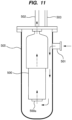
- FIG. 11 is a schematic diagram showing a conventional example of a pump apparatus for pumping up the liquefied gas.
- a pump 500 is installed in a vertical suction container 505 coupled to a liquefied-gas storage tank (not shown) in which the liquefied gas is stored.
- the liquefied gas is introduced into the suction container 505 through a suction port 501, and the suction container 505 is filled with the liquefied gas.
- the entire pump 500 is immersed in the liquefied gas. Therefore, the pump 500 is a submersible pump that can operate in the liquefied gas.
- the pump 500 is in operation, the liquefied gas is discharged by the pump 500 through a discharge port 502.
- a part of the liquefied gas in the suction container 505 is vaporized into gas, and this gas is discharged from the suction container 505 through a vent line 503.
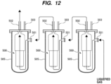
- multiple pump apparatuses may be coupled in series as shown in FIG. 12 .
- the liquefied gas is sequentially pressurized by pumps 500 of the multiple pump apparatuses.
- the pumps 500 are started sequentially in the order from the upstream pump.
- the pumps 500 are stopped sequentially in the order from the downstream pump.
- the liquefied gas When the pump 500 is operating, the liquefied gas is pressurized by the rotation of the impeller. Therefore, a thrust balance mechanism of the pump 500 works and no excessive load is applied to the sliding parts, such as bearings. However, when the pump 500 is not in operation, the thrust balance mechanism does not work. As a result, the liquefied gas delivered from the other pump 500 forcibly rotates the impeller, resulting in damage to the sliding parts, such as the bearings. In particular, the liquefied gas has a low viscosity, and the sliding parts, such as the bearings, are easily worn out by the unintended rotation of the impeller. Furthermore, when the operation of the downstream pump 500 is stopped, the same problem may happen because the upstream pump 500 is still operating. In addition, when the pump 500 is suddenly stopped due to malfunction of the pump 500, the same problem may happen.
- the present invention provides a method of starting and stopping a submersible pump among a plurality of submersible pumps coupled in series, while preventing rotation of an impeller of another submersible pump that is not in operation.
- a method of starting a plurality of pump apparatuses including at least a first pump apparatus and a second pump apparatus coupled in series, comprising: starting a first submersible pump arranged in a first suction container of the first pump apparatus to deliver liquefied gas through a first flow-path switching device arranged in the first suction container to a second suction container of the second pump apparatus; passing the liquefied gas through a second flow-path switching device arranged in the second suction container while the liquefied gas bypasses a second submersible pump arranged in the second suction container; and then starting the second submersible pump.
- each of the first flow-path switching device and the second flow-path switching device includes: a flow-passage structure having a pump-side flow passage, a container-side flow passage, and an outlet flow passage; and a valve element arranged in the flow-passage structure, the valve element being configured to allow the outlet flow passage to selectively communicate with either the pump-side flow passage or the container-side flow passage, the pump-side flow passage communicating with a discharge outlet of the corresponding submersible pump, the container-side flow passage communicating with an interior of the corresponding suction container, and the outlet flow passage communicating with a discharge port of the corresponding suction container.
- the pump apparatus 100 includes a submersible pump 1 for delivering the liquefied gas, a suction container 2 in which the submersible pump 1 is accommodated, and a flow-path switching device 5 for preventing rotation of impellers 15 of the submersible pump 1 when the submersible pump 1 is not in operation.
- the suction container 2 has a suction port 7 and a discharge port 8.
- the liquefied gas is introduced into the suction container 2 through the suction port 7, and the suction container 2 is filled with the liquefied gas.
- the entire submersible pump 1 is immersed in the liquefied gas. Therefore, the submersible pump 1 is configured to be able to operate in the liquefied gas.
- the submersible pump 1 includes an electric motor 11 having a motor rotor 9 and a motor stator 10, a rotation shaft 12 coupled to the electric motor 11, a plurality of bearings 14 that rotatably support the rotation shaft 12, impellers 15 fixed to the rotation shaft 12, and a pump casing 16 in which the impellers 15 are housed.
- the flow-path switching device 5 is disposed in the suction container 2. More specifically, the flow-path switching device 5 is coupled to both a discharge outlet 4 of the submersible pump 1 and the discharge port 8 of the suction container 2. Specific configurations of the flow-path switching device 5 will be described later.
- the motor 11 When electric power is supplied to the motor 11 through a power cable (not shown), the motor 11 rotates the rotation shaft 12 and the impellers 15 together. As the impellers 15 rotate, the liquefied gas is sucked into the submersible pump 1 through a suction inlet 3 and discharged into the flow-path switching device 5 through a discharge flow path 17 and the discharge outlet 4. The liquefied gas passes through the flow-path switching device 5 and is discharged through the discharge port 8 of the suction container 2.
- a suction valve 22 is coupled to the suction port 7, and a discharge valve 23 is coupled to the discharge port 8.
- a drain line 25 is coupled to a bottom of the suction container 2, and a drain valve 26 is coupled to the drain line 25.
- the suction port 7 is provided on a side wall of the suction container 2 and is located higher than the bottom of the suction container 2.
- the discharge port 8 is provided on an upper portion of the suction container 2 and is located higher than the suction port 7.
- FIG. 2 is a cross-sectional view showing an embodiment of detailed configuration of the flow-path switching device 5.
- the flow-path switching device 5 includes a flow-passage structure 45 and a valve element 47 arranged in the flow-passage structure 45.
- the flow-passage structure 45 has a pump-side flow passage 41, a container-side flow passage 42, and an outlet flow passage 43 therein.
- the pump-side flow passage 41 communicates with the discharge outlet 4 of the submersible pump 1
- the container-side flow passage 42 communicates with an interior of the suction container 2
- the outlet flow passage 43 communicates with the discharge port 8 of the suction container 2.
- FIG. 2 shows a state of the flow-path switching device 5 when the submersible pump 1 is not in operation.
- the valve element 47 is pressed against the flow-passage structure 45 by a spring 50 to thereby close the pump-side flow passage 41.
- the flow-passage structure 45 has a valve seat 51 formed around an outlet of the pump-side flow passage 41.
- the valve element 47 is pressed against the valve seat 51 by the spring 50. Therefore, when the valve element 47 is pressed against the valve seat 51, the pump-side flow passage 41 is closed, while the container-side flow passage 42 and the outlet flow passage 43 are in fluid communication.
- the container-side flow passage 42 is open in the suction container 2 and communicates with the suction port 7 through the interior of the suction container 2.
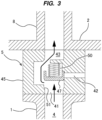
- FIG. 3 shows a state of the flow-path switching device 5 when the submersible pump 1 is in operation.
- the liquefied gas is discharged from the discharge outlet 4 of the submersible pump 1 and flows into the pump-side flow passage 41 of the flow-path switching device 5.
- the liquefied gas flowing through the pump-side flow passage 41 moves the valve element 47 against the force of the spring 50, thus opening the pump-side flow passage 41 and closing the container-side flow passage 42 with the valve element 47.
- the fluid communication between the pump-side flow passage 41 and the outlet flow passage 43 is established.
- the valve element 47 When the operation of the submersible pump 1 is stopped, the valve element 47 is pressed against the valve seat 51 by the spring 50. As a result, as shown in FIG. 2 , the pump-side flow passage 41 is closed, while the container-side flow passage 42 and the outlet flow passage 43 communicate with each other. In this way, the flow-path switching device 5 of this embodiment operates only by the spring 50 and the flow of liquefied gas.
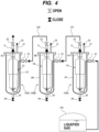
- FIG. 4 is a schematic diagram showing an embodiment of a pump system including a plurality of pump apparatuses 100A, 100B, and 100C coupled in series.
- the plurality of pump apparatuses 100A, 100B, and 100C have the same configuration as the pump apparatus 100 described with reference to FIGS. 1 to 6 .
- submersible pump, suction container, and flow-path switching device of the pump apparatus 100A are referred to as submersible pump 1A, suction container 2A, and flow-path switching device 5A, respectively.
- Submersible pump, suction container, and flow-path switching device of the pump apparatus 100B are referred to as submersible pump 1B, suction container 2B, and flow-path switching device 5B, respectively.
- Submersible pump, suction container, and flow-path switching device of the pump apparatus 100C are referred to as submersible pump 1C, suction container 2C, and flow-path switching device 5C, respectively.
- the pump apparatus 100A is disposed upstream of the pump apparatus 100B, which is disposed upstream of the pump apparatus 100C.
- the suction port 7 of the pump apparatus 100A is coupled to a liquefied-gas storage tank 105 in which the liquefied gas is stored.
- the pump apparatus 100A is coupled in series to the pump apparatus 100B by a communication line 107, and the pump apparatus 100B is coupled in series to the pump apparatus 100C by a communication line 108. More specifically, the discharge port 8 of the pump apparatus 100A is coupled to the suction port 7 of the pump apparatus 100B by the communication line 107, and the discharge port 8 of the pump apparatus 100B is coupled to the suction port 7 of the pump apparatus 100C by the communication line 108.
- the submersible pumps 1A, 1B, and 1C are coupled in series in the order of the submersible pump 1A, the submersible pump 1B, and the submersible pump 1C.
- the liquefied gas is successively pressurized by these submersible pumps 1A, 1B, and 1C.
- the flow-path switching devices 5A, 5B, and 5C are in the state shown in FIG. 3 .
- the submersible pumps 1A, 1B, and 1C are started in sequence in the order from the upstream side. Specifically, the submersible pump 1A is started first, then the submersible pump 1B is started, and finally the submersible pump 1C is started.
- FIG. 5 is a diagram illustrating a state in which the submersible pump 1A is started while the submersible pumps 1B and 1C are not in operation.
- the liquefied gas is delivered by the submersible pump 1A through the flow-path switching device 5A to the suction container 2B of the pump apparatus 100B.
- the flow-path switching device 5A is in the state shown in FIG. 3 .
- the flow-path switching device 5B is in the state shown in FIG. 2 . Therefore, the liquefied gas passes through the flow-path switching device 5B while bypassing the submersible pump 1B (i.e., the liquefied gas does not flow through the submersible pump 1B).
- the liquefied gas is further delivered from the pump apparatus 100B to the suction container 2C of the pump apparatus 100C. Since the submersible pump 1C is also not in operation, the flow-path switching device 5C is in the state shown in FIG. 2 . Therefore, the liquefied gas passes through the flow-path switching device 5C while bypassing the submersible pump 1C (i.e., the liquefied gas does not flow through the submersible pump 1C).
- FIG. 6 is a diagram illustrating a state in which the submersible pump 1B is started while the submersible pump 1A is operating, and the submersible pump 1C is not operating.
- the liquefied gas is transferred by the submersible pump 1B through the flow-path switching device 5B to the suction container 2C of the pump apparatus 100C.
- the flow-path switching device 5B is in the state shown in FIG. 3 .
- the flow-path switching device 5C is in the state shown in FIG. 2 . Therefore, the liquefied gas passes through the flow-path switching device 5C while bypassing the submersible pump 1C (i.e., the liquefied gas does not flow through the submersible pump 1C).
- the submersible pump 1C is started.
- the submersible pumps 1A and 1B are in operation.
- the state in which all of the submersible pumps 1A, 1B, and 1C are in operation is shown in FIG. 4 .
- the submersible pumps 1A, 1B, and 1C are started in sequence in the order from the upstream side.
- the operations of the submersible pumps 1A, 1B, and 1C are stopped in sequence in the order from the downstream side. Specifically, first, the operation of the submersible pump 1C is stopped, then the operation of the submersible pump 1B is stopped, and finally the operation of the submersible pump 1A is stopped.
- FIG. 7 is a diagram illustrating a state in which the operation of the submersible pump 1C is stopped and the submersible pumps 1A and 1B are in operation.
- the flow-path switching device 5C is in the state shown in FIG. 2 . Therefore, the liquefied gas passes through the flow-path switching device 5C while bypassing the submersible pump 1C (i.e., the liquefied gas does not flow through the submersible pump 1C).
- the flow-path switching device 5A is in the state shown in FIG. 3 . Therefore, the liquefied gas is delivered by the submersible pump 1A through the flow-path switching device 5A to the suction container 2B of the pump apparatus 100B.
- the submersible pump 1A is stopped.
- the submersible pumps 1B and 1C are not in operation. In this manner, the submersible pumps 1A, 1B, and 1C are stopped in sequence in the order from the downstream side.
- the flow-path switching devices can allow the liquefied gas to bypass the submersible pumps that are not in operation. Therefore, the impellers of the submersible pumps that are not in operation do not rotate, and as a result, damage to the sliding parts of the submersible pumps, such as the bearings, can be prevented.
- the embodiment of the pump system shown in FIGS. 4 to 8 includes three pump apparatuses 100A, 100B, and 100C coupled in series, while the number of pump apparatuses is not limited to this embodiment.
- the pump system may include only two pump apparatuses coupled in series, or may include four or more pump apparatuses coupled in series.
- the multiple submersible pumps coupled in series are started and stopped in the same manner as in the above-described embodiment.
- FIG. 9 is a schematic diagram showing another embodiment of a pump system including a plurality of pump apparatuses coupled in series. Configuration and operation of this embodiment that will not be specifically described are the same as those of the embodiment described with reference to FIG. 7 , and therefore duplicated description will be omitted.
- the pump system of the embodiment shown in FIG. 9 further includes pump apparatuses 100D, 100E, and 100F coupled in series, in addition to the pump apparatuses 100A, 100B, and 100C coupled in series.
- the pump apparatus 100D includes a suction container 2D, a submersible pump 1D disposed in the suction container 2D, and a flow-path switching device 5D disposed in the suction container 2D.
- the pump apparatus 100E includes a suction container 2E, a submersible pump 1E disposed in the suction container 2E, and a flow-path switching device 5E disposed in the suction container 2E.
- the pump apparatus 100F includes a suction container 2F, a submersible pump 1F disposed in the suction container 2F, and a flow-path switching device 5F disposed in the suction container 2F.
- the pump apparatus 100D is coupled in series to the pump apparatus 100E by a communication line 109, and the pump apparatus 100E is coupled in series to the pump apparatus 100F by a communication line 110. More specifically, a discharge port of the pump apparatus 100D is coupled to a suction port of the pump apparatus 100E by the communication line 109, and a discharge port of the pump apparatus 100E is coupled to a suction port of the pump apparatus 100F by the communication line 110.
- the pump apparatuses 100D, 100E, and 100F are arranged in parallel with the pump apparatuses 100A, 100B, and 100C.
- the pump apparatuses 100A, 100B, 100C, 100D, 100E, and 100F have the same configuration as the pump apparatus 100 described with reference to FIGS. 1 to 3 , and therefore duplicated descriptions thereof will be omitted.
- the pump apparatuses 100A and 100D are coupled to the liquefied-gas storage tank 105 in which the liquefied gas is stored. According to the embodiment shown in FIG. 9 , the liquefied gas is pumped by the submersible pumps 1A to 1C of the pump apparatuses 100A to 100C and by the submersible pumps 1D to 1F of the pump apparatuses 100D to 100F arranged in parallel.
- the submersible pumps 1D, 1E, and 1F are started in sequence in the order from the upstream side, as well as the submersible pumps 1A, 1B, and 1C. Specifically, the submersible pump 1D is started first, then the submersible pump 1E is started, and finally the submersible pump 1F is started.
- the submersible pumps 1D, 1E, and 1F are stopped in sequence in the order from the downstream side, as well as the submersible pumps 1A, 1B, and 1C. Specifically, the submersible pump 1F is stopped first, then the submersible pump 1E is stopped, and finally the submersible pump 1D is stopped.
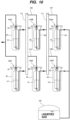
- FIG. 10 is a schematic diagram showing yet another embodiment of a pump system including a plurality of pump apparatuses coupled in series. Configuration and operation of this embodiment that will not be specifically described are the same as those of the embodiment described with reference to FIG. 9 , and therefore repetitive description will be omitted.
- the communication line 107 coupling the pump apparatus 100A to the pump apparatus 100B is coupled to the communication line 109 coupling the pump apparatus 100D to the pump apparatus 100E by an intermediate header 111.
- the communication line 108 coupling the pump apparatus 100B to the pump apparatus 100C is coupled to the communication line 110 coupling the pump apparatus 100E to the pump apparatus 100F by an intermediate header 112.
- the submersible pumps 1A, 1B, and 1C are started in sequence in the order from the upstream side, and the submersible pumps 1D, 1E, and 1F are also started in sequence in the order from the upstream side.
- the operations of the submersible pumps 1A, 1B, and 1C are stopped in sequence in the order from the downstream side, and the operations of the submersible pumps 1D, 1E, and 1F are also stopped in sequence in the order from the downstream side.
- the pump apparatuses 100A to 100C are also coupled in series to the pump apparatuses 100D to 100F by the intermediate headers 111, 112. As a result, various flows of the liquefied gas are formed, allowing various operations of the pump apparatuses 100A to 100C and the pump apparatuses 100D to 100F. For example, it is possible to stop the operation of the pump apparatus 100C or the pump apparatus100F for maintenance or depending on the pressure required by a user.
- the present invention is applicable to a method of starting and stopping a submersible pump used for delivering liquefied gas, such as liquid hydrogen, liquid nitrogen, liquefied ammonia, liquefied natural gas, liquefied ethylene gas, or liquefied petroleum gas.
- liquefied gas such as liquid hydrogen, liquid nitrogen, liquefied ammonia, liquefied natural gas, liquefied ethylene gas, or liquefied petroleum gas.
Landscapes
- Engineering & Computer Science (AREA)
- Mechanical Engineering (AREA)
- General Engineering & Computer Science (AREA)
- Structures Of Non-Positive Displacement Pumps (AREA)
- Filling Or Discharging Of Gas Storage Vessels (AREA)
- Control Of Non-Positive-Displacement Pumps (AREA)
- Control Of Positive-Displacement Pumps (AREA)
Applications Claiming Priority (2)
| Application Number | Priority Date | Filing Date | Title |
|---|---|---|---|
| JP2022085897A JP7804533B2 (ja) | 2022-05-26 | 2022-05-26 | 直列に連結されたポンプ装置の始動方法および停止方法 |
| PCT/JP2023/018086 WO2023228792A1 (ja) | 2022-05-26 | 2023-05-15 | 直列に連結されたポンプ装置の始動方法および停止方法 |
Publications (1)
| Publication Number | Publication Date |
|---|---|
| EP4534849A1 true EP4534849A1 (de) | 2025-04-09 |
Family
ID=88919189
Family Applications (1)
| Application Number | Title | Priority Date | Filing Date |
|---|---|---|---|
| EP23811666.9A Pending EP4534849A1 (de) | 2022-05-26 | 2023-05-15 | Startverfahren und stoppverfahren für in reihe geschaltete pumpvorrichtungen |
Country Status (8)
| Country | Link |
|---|---|
| US (1) | US12595799B2 (de) |
| EP (1) | EP4534849A1 (de) |
| JP (2) | JP7804533B2 (de) |
| KR (1) | KR20250011670A (de) |
| CN (1) | CN119183503A (de) |
| AU (1) | AU2023277028A1 (de) |
| CA (1) | CA3254761A1 (de) |
| WO (1) | WO2023228792A1 (de) |
Families Citing this family (1)
| Publication number | Priority date | Publication date | Assignee | Title |
|---|---|---|---|---|
| JP2026020758A (ja) * | 2024-07-29 | 2026-02-10 | 三菱重工業株式会社 | ポンプシステム |
Family Cites Families (7)
| Publication number | Priority date | Publication date | Assignee | Title |
|---|---|---|---|---|
| JPS59159795A (ja) | 1983-03-04 | 1984-09-10 | Yakult Honsha Co Ltd | 微生物変換による抱合型ウルソデオキシコ−ル酸の製造方法 |
| JPS59159795U (ja) | 1983-04-12 | 1984-10-26 | 株式会社荏原製作所 | サブマ−ジドモ−タポンプ |
| JPS6231680A (ja) | 1985-08-05 | 1987-02-10 | 株式会社日立製作所 | エレベ−タの乗り場かご位置表示器の点灯方法 |
| JPS6231680U (de) | 1985-08-09 | 1987-02-25 | ||
| JPH06307376A (ja) * | 1993-04-22 | 1994-11-01 | Hitachi Ltd | 液化ガスタンク用潜没ポンプ装置 |
| JP2007024166A (ja) * | 2005-07-15 | 2007-02-01 | Taiyo Nippon Sanso Corp | 低温液化ガス供給装置 |
| CA3202585A1 (en) | 2020-11-27 | 2022-06-02 | Ebara Corporation | Fluid-path switching apparatus and method of preventing idling rotation of submersible pump |
-
2022
- 2022-05-26 JP JP2022085897A patent/JP7804533B2/ja active Active
-
2023
- 2023-05-15 US US18/867,622 patent/US12595799B2/en active Active
- 2023-05-15 AU AU2023277028A patent/AU2023277028A1/en active Pending
- 2023-05-15 WO PCT/JP2023/018086 patent/WO2023228792A1/ja not_active Ceased
- 2023-05-15 CN CN202380040230.8A patent/CN119183503A/zh active Pending
- 2023-05-15 EP EP23811666.9A patent/EP4534849A1/de active Pending
- 2023-05-15 KR KR1020247042177A patent/KR20250011670A/ko active Pending
- 2023-05-15 CA CA3254761A patent/CA3254761A1/en active Pending
-
2026
- 2026-01-09 JP JP2026002871A patent/JP2026042986A/ja active Pending
Also Published As
| Publication number | Publication date |
|---|---|
| WO2023228792A1 (ja) | 2023-11-30 |
| JP7804533B2 (ja) | 2026-01-22 |
| KR20250011670A (ko) | 2025-01-21 |
| AU2023277028A1 (en) | 2025-01-09 |
| CA3254761A1 (en) | 2025-04-14 |
| JP2026042986A (ja) | 2026-03-11 |
| JP2023173562A (ja) | 2023-12-07 |
| CN119183503A (zh) | 2024-12-24 |
| US20250341215A1 (en) | 2025-11-06 |
| US12595799B2 (en) | 2026-04-07 |
Similar Documents
| Publication | Publication Date | Title |
|---|---|---|
| EP4253759A1 (de) | Strömungswegschaltvorrichtung und verfahren zur verhinderung des trockenlaufs einer tauchpumpe | |
| US20070190389A1 (en) | Fuel cell system having a fuel cell, a hydrogen storage tank, and an anode circuit | |
| JP2026042986A (ja) | ポンプシステム | |
| EP2250697B1 (de) | Verfahren und vorrichtung zum betreiben eines brennstoffzellensystems mit einem im brennstoffkreislauf des brennstoffzellensystems angeordneten rückführungsgebläse | |
| EP4542051A1 (de) | Pumpvorrichtung | |
| CN107027332A (zh) | 用于燃料电池系统的至少一个燃料电池单元的冷却系统以及用于冷却至少一个燃料电池单元的方法 | |
| JP3514855B2 (ja) | 低温液化ガス用ポンプ | |
| EP4534848A1 (de) | Trocknungsverfahren, kühlverfahren und erwärmungsverfahren für eine pumpvorrichtung | |
| AU2024348633A1 (en) | Cooling-down method for pump apparatus | |
| KR102166165B1 (ko) | 초전도 전기모터로 구동되는 액체로켓엔진의 추진제 공급 장치 | |
| CN112302723B (zh) | 膨胀机和燃料电池系统 | |
| KR20210033934A (ko) | 연통된 공간에 모터와 펌프가 존재하는 액체로켓엔진의 추진제 공급 장치 | |
| CN121889613A (zh) | 泵装置的降温方法 | |
| CN1841829B (zh) | 具有再循环工作燃料的燃料电池设备 | |
| JP3340852B2 (ja) | 液体ポンプ | |
| WO2026094534A1 (ja) | ポンプシステム | |
| WO2026028497A1 (ja) | ポンプシステム | |
| CN120946933A (zh) | 一种车载液氢供应系统及其车辆 | |
| JPS6133998B2 (de) |
Legal Events
| Date | Code | Title | Description |
|---|---|---|---|
| STAA | Information on the status of an ep patent application or granted ep patent |
Free format text: STATUS: THE INTERNATIONAL PUBLICATION HAS BEEN MADE |
|
| PUAI | Public reference made under article 153(3) epc to a published international application that has entered the european phase |
Free format text: ORIGINAL CODE: 0009012 |
|
| STAA | Information on the status of an ep patent application or granted ep patent |
Free format text: STATUS: REQUEST FOR EXAMINATION WAS MADE |
|
| 17P | Request for examination filed |
Effective date: 20241219 |
|
| AK | Designated contracting states |
Kind code of ref document: A1 Designated state(s): AL AT BE BG CH CY CZ DE DK EE ES FI FR GB GR HR HU IE IS IT LI LT LU LV MC ME MK MT NL NO PL PT RO RS SE SI SK SM TR |
|
| DAV | Request for validation of the european patent (deleted) | ||
| DAX | Request for extension of the european patent (deleted) |