EP4534820A2 - Gasturbinenmotor mit abscheidern für mitgeführte partikel - Google Patents
Gasturbinenmotor mit abscheidern für mitgeführte partikel Download PDFInfo
- Publication number
- EP4534820A2 EP4534820A2 EP24204826.2A EP24204826A EP4534820A2 EP 4534820 A2 EP4534820 A2 EP 4534820A2 EP 24204826 A EP24204826 A EP 24204826A EP 4534820 A2 EP4534820 A2 EP 4534820A2
- Authority
- EP
- European Patent Office
- Prior art keywords
- particle separator
- housing
- turbine engine
- wall
- helical
- Prior art date
- Legal status (The legal status is an assumption and is not a legal conclusion. Google has not performed a legal analysis and makes no representation as to the accuracy of the status listed.)
- Pending
Links
Images





Classifications
-
- F—MECHANICAL ENGINEERING; LIGHTING; HEATING; WEAPONS; BLASTING
- F02—COMBUSTION ENGINES; HOT-GAS OR COMBUSTION-PRODUCT ENGINE PLANTS
- F02C—GAS-TURBINE PLANTS; AIR INTAKES FOR JET-PROPULSION PLANTS; CONTROLLING FUEL SUPPLY IN AIR-BREATHING JET-PROPULSION PLANTS
- F02C3/00—Gas-turbine plants characterised by the use of combustion products as the working fluid
- F02C3/14—Gas-turbine plants characterised by the use of combustion products as the working fluid characterised by the arrangement of the combustion chamber in the plant
-
- F—MECHANICAL ENGINEERING; LIGHTING; HEATING; WEAPONS; BLASTING
- F02—COMBUSTION ENGINES; HOT-GAS OR COMBUSTION-PRODUCT ENGINE PLANTS
- F02C—GAS-TURBINE PLANTS; AIR INTAKES FOR JET-PROPULSION PLANTS; CONTROLLING FUEL SUPPLY IN AIR-BREATHING JET-PROPULSION PLANTS
- F02C7/00—Features, components parts, details or accessories, not provided for in, or of interest apart form groups F02C1/00 - F02C6/00; Air intakes for jet-propulsion plants
- F02C7/04—Air intakes for gas-turbine plants or jet-propulsion plants
- F02C7/05—Air intakes for gas-turbine plants or jet-propulsion plants having provisions for obviating the penetration of damaging objects or particles
- F02C7/052—Air intakes for gas-turbine plants or jet-propulsion plants having provisions for obviating the penetration of damaging objects or particles with dust-separation devices
-
- F—MECHANICAL ENGINEERING; LIGHTING; HEATING; WEAPONS; BLASTING
- F02—COMBUSTION ENGINES; HOT-GAS OR COMBUSTION-PRODUCT ENGINE PLANTS
- F02C—GAS-TURBINE PLANTS; AIR INTAKES FOR JET-PROPULSION PLANTS; CONTROLLING FUEL SUPPLY IN AIR-BREATHING JET-PROPULSION PLANTS
- F02C7/00—Features, components parts, details or accessories, not provided for in, or of interest apart form groups F02C1/00 - F02C6/00; Air intakes for jet-propulsion plants
- F02C7/26—Starting; Ignition
- F02C7/264—Ignition
-
- F—MECHANICAL ENGINEERING; LIGHTING; HEATING; WEAPONS; BLASTING
- F02—COMBUSTION ENGINES; HOT-GAS OR COMBUSTION-PRODUCT ENGINE PLANTS
- F02C—GAS-TURBINE PLANTS; AIR INTAKES FOR JET-PROPULSION PLANTS; CONTROLLING FUEL SUPPLY IN AIR-BREATHING JET-PROPULSION PLANTS
- F02C7/00—Features, components parts, details or accessories, not provided for in, or of interest apart form groups F02C1/00 - F02C6/00; Air intakes for jet-propulsion plants
- F02C7/30—Preventing corrosion or unwanted deposits in gas-swept spaces
-
- F—MECHANICAL ENGINEERING; LIGHTING; HEATING; WEAPONS; BLASTING
- F05—INDEXING SCHEMES RELATING TO ENGINES OR PUMPS IN VARIOUS SUBCLASSES OF CLASSES F01-F04
- F05D—INDEXING SCHEME FOR ASPECTS RELATING TO NON-POSITIVE-DISPLACEMENT MACHINES OR ENGINES, GAS-TURBINES OR JET-PROPULSION PLANTS
- F05D2240/00—Components
- F05D2240/35—Combustors or associated equipment
-
- F—MECHANICAL ENGINEERING; LIGHTING; HEATING; WEAPONS; BLASTING
- F05—INDEXING SCHEMES RELATING TO ENGINES OR PUMPS IN VARIOUS SUBCLASSES OF CLASSES F01-F04
- F05D—INDEXING SCHEME FOR ASPECTS RELATING TO NON-POSITIVE-DISPLACEMENT MACHINES OR ENGINES, GAS-TURBINES OR JET-PROPULSION PLANTS
- F05D2250/00—Geometry
- F05D2250/20—Three-dimensional
- F05D2250/25—Three-dimensional helical
-
- F—MECHANICAL ENGINEERING; LIGHTING; HEATING; WEAPONS; BLASTING
- F05—INDEXING SCHEMES RELATING TO ENGINES OR PUMPS IN VARIOUS SUBCLASSES OF CLASSES F01-F04
- F05D—INDEXING SCHEME FOR ASPECTS RELATING TO NON-POSITIVE-DISPLACEMENT MACHINES OR ENGINES, GAS-TURBINES OR JET-PROPULSION PLANTS
- F05D2260/00—Function
- F05D2260/60—Fluid transfer
- F05D2260/607—Preventing clogging or obstruction of flow paths by dirt, dust, or foreign particles
Definitions
- the present disclosure relates to gas turbine engines in general and to gas turbine engine including entrained particle separation devices in particular.
- the debris may, for example, clog cooling passages and build up on impingement surfaces, reducing the efficiency of heat transfer.
- Air contamination primarily occurs at takeoff and landing due to the higher concentration of dirt particles near the ground. Once the dirt reaches the hottest part of the engine, in the combustor and the high pressure turbine, it tends to have a very small particle size because it has passed through the compressor. What is needed is an improved system for removing entrained articles from air passing within a turbine engine.
- a turbine engine having an axial centerline includes a compressor section, a combustor section, an outer casing, an inner diffuser case, a turbine section, a particle separator, and a mechanism configured to produce an electrostatically charged surface on a portion of the particle separator.
- the combustor section has an annular combustor.
- the outer casing is disposed radially outside of and spaced apart from the annular combustor.
- a diffuser outer diameter (OD) flow path is disposed radially between the outer casing and the annular combustor.
- the inner diffuser case is disposed radially inside of and spaced apart from the annular combustor.
- a diffuser inner diameter (ID) flow path is disposed radially between the annular combustor and the inner diffuser case.
- the particle separator is disposed within at least one of the diffuser OD flow path or the diffuser ID flow path.
- the particle separator includes a housing having an interior cavity defined between an exterior wall and an interior wall. The housing extends between a forward end and an aft end.
- the particle separator further includes a plurality of helical dividers, at least one collection pocket, at least one inlet aperture, and a plurality of exit apertures.
- the helical dividers are disposed within the housing interior cavity.
- the first passage may be defined by a first helical divider and the electrostatically charged surface
- the particle separator may include a second passage defined by a second helical divider and the housing interior wall or the housing exterior wall.
- housing exterior wall and the housing interior wall may be concentric.
- first and second helical dividers each have an outer wall end and a distal end, and the respective outer wall ends of the first and second helical dividers are each connected to the housing exterior wall.
- the at least one collection pocket may include a first collection pocket disposed adjacent the outer wall end of the second helical divider.
- the distal end of the first said helical divider may be disposed radially inside of and spaced apart from the first collection pocket.
- the electrostatically charged surface may be at least a portion of the housing exterior wall.
- the mechanism configured to produce an electrostatically charged surface may be in communication with a combustor igniter.
- the first passage may be defined by a first helical divider and the electrostatically charged surface portion of the housing exterior wall
- the particle separator may include a second passage defined by a second helical divider and the housing interior wall.
- the first passage may be defined by a first helical divider and the electrostatically charged surface portion of the housing interior wall
- the particle separator may include a second passage defined by a second helical divider and the housing exterior wall, and the housing exterior wall may be disposed radially outside of the housing interior wall.
- first and second helical dividers may each have an outer wall end and a distal end, and the respective outer wall ends of the first and second helical dividers may each be connected to the housing interior wall.
- FIG. 1 shows a partially sectioned diagrammatic view of a geared gas turbine engine 20.
- the gas turbine engine 20 extends along an axial centerline 22 between an upstream air flow inlet 24 and a downstream air flow exhaust 26.
- the gas turbine engine 20 includes a fan section 28, a compressor section 30, a combustor section 32, and a turbine section 34.
- the combustor section 32 includes a combustor 35.
- the compressor section 30 includes a low pressure compressor (LPC) 36 and a high pressure compressor (HPC) 38.
- the turbine section 34 includes a high pressure turbine (HPT) 40 and a low pressure turbine (LPT) 42.
- the engine sections are arranged sequentially along the centerline 22.
- the fan section 28 is connected to a geared architecture 44, for example, through a fan shaft 46.
- the geared architecture 44 and the LPC 36 are connected to and driven by the LPT 42 through a low speed shaft 48.
- the HPC 38 is connected to and driven by the HPT 40 through a high speed shaft 50.
- the terms "forward”, “leading”, “aft, “trailing” are used herein to indicate the relative position of a component or surface. As core gas air passes through the engine 20, a "leading edge" of a stator vane or rotor blade encounters core gas air before the "trailing edge" of the same.
- a conventional axial engine 20 such as that shown in FIG.
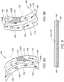
- the first particle separator 58A shown in FIG. 6 includes a plurality of helical dividers 100, each having an outer wall end 102A and a distal end 104A.
- the outer wall end 102A is engaged with the housing exterior wall 114.
- the helical dividers 100 shown in FIG. 6 extend circumferentially and spiral radially inward. A portion of each helical divider 100 defines an outer passage 112 between the helical divider 100 and the exterior wall 114, and a portion of each helical divider 100 defines an inner passage 124 between the helical divider 100 and the interior wall 116.
- the distal end 104A of each helical divider 100 is spaced apart from the interior wall 116.
- the inlet apertures 106 are in fluid communication with the outer passages 112 formed by the helical dividers 100. In some embodiments, it may be possible to utilize a single inlet aperture 106.
- the inlet apertures 106 are diagrammatically illustrated as circular openings that may be disposed at the forward end 120 (see FIG. 2 ) of the housing 98.
- the present disclosure is not limited to circular shaped inlet apertures 106. Any inlet aperture 106 configuration that provides a fluid communication path from outside of the particle separator 58A into the outer passages 112 may be used.
- the present disclosure is not limited to inlet apertures 106 disposed at the housing forward end 120; e.g., in some embodiments inlet apertures 106 may extend through the housing exterior wall 114 into the outer passages 112.
- Each collection pocket 110 may be defined by the housing interior wall 116, the inner wall end 102B of a respective helical divider 100, and a pocket wall 126, and each collection pocket 110 includes an opening for receiving particulate debris from the inner passage 124 as will be detailed herein. Adjacent to the collection pocket 110, the inner passage 124 spirals outwardly, extending between the collection pocket 110 and the outer passage 112 before terminating at the distal end 104B of the helical divider 100.
- the inlet apertures 106 are in fluid communication with the inner passages 124 formed by the helical dividers 100. In some embodiments, it may be possible to utilize a single inlet aperture 106.
- the inlet apertures 106 are diagrammatically illustrated as circular openings that may be disposed at the forward end 120 (see FIG. 2 ) of the housing 98.
- the present disclosure is not limited to circular shaped inlet apertures 106. Any inlet aperture 106 configuration that provides a fluid communication path from outside of the particle separator 58B into the inner passages 124 may be used. In like manner, the present disclosure is not limited to inlet apertures 106 disposed at the housing forward end 120; e.g., in some embodiments inlet apertures 106 may extend through the housing interior wall 116 and into the inner passages 124.
- the exit apertures 108 are in fluid communication with the outer passages 112 formed by the helical dividers 100.
- the exit apertures 108 are diagrammatically illustrated as circular openings, but the present disclosure is not limited to circular apertures. Any configuration of an exit aperture 108 that provides a fluid communication path from a respective outer passage 112 to outside of the particle separator 58B (e.g., through the housing exterior wall 114 to outside of the housing 98) may be used.
- the mechanism 96 may be controlled between an "on mode” wherein the separator portion is electrostatically charged and an "off mode” wherein the separator portion is not electrostatically charged to prevent particle accumulation on the charged portion.
- the controller 134 may be configured to control and/or receive signals therefrom to perform the functions described herein.
- the controller 134 may include any type of computing device, computational circuit, processor(s), CPU, computer, or the like capable of executing a series of instructions that are stored in memory.
- the instructions may include an operating system, and/or executable software modules such as program files, system data, buffers, drivers, utilities, and the like.
- the executable instructions may apply to any functionality described herein to enable the system to accomplish the same algorithmically and/or coordination of system components.
- the controller 134 includes or is in communication with one or more memory devices.
- the present disclosure is not limited to any particular type of memory device, and the memory device may store instructions and/or data in a non-transitory manner. Examples of memory devices that may be used include read-only memory, random access memory, volatile memory, non-volatile memory, static memory, dynamic memory, flash memory, cache memory, and/or any device that stores digital information. Communications between the controller and other system components may be via a hardwire connection or via a wireless connection.
- Particles entrained in air very often possess a static charge (positive or negative charge).
- the aforesaid static charge may result from contact between the particles and other objects; e.g., other particles and/or surfaces.
- the compressing work performed on the air by the compressor section 30 upstream of the combustor section 32 may increase the probability of entrained particles possessing a static charge.
- the compressing work may also decrease the percentage of particles having a relatively larger diameter and increase the percentage of particles having a relatively smaller diameter.
- particle separators 58 are configured such that a portion of a particle separator 58 possesses an electrostatic charge continuously, intermittently, or selectively.
- the electrostatically charged portion of the particle separator 58 facilitates particle separation by attracting the particles in a predetermined direction for subsequent collection.
- the air flow passing through the separator 58 that has been subjected to particle separation and collection is "cleaner" (i.e., less particulate matter) than the "dirty" air that entered the particle separator 58.
- the present disclosure is not limited to any particular portion of a separator 58 as the electrostatically charged surface. In the particle separator 58A embodiment shown in FIG.
- the housing exterior wall 114 (or a portion thereof) is electrostatically charged and is electrically insulated from the remainder of the particle separator 58A.
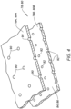
- one or more electrically conductive panels 136 may be attached to, and electrically insulated from (via insulators 138), the exterior wall 114 of the particle separator 58A, to function as the electrostatically charged surface.
- the polarity of the electrostatically charged surface may be chosen based on the polarity of particles entrained within the air flow.
- air is drawn into the turbine engine 20 through an air flow inlet 24 and is typically directed through a fan section 28.
- the air flow exiting the fan section 28 enters the compressor section 30 where it is worked to a higher pressure and temperature.
- the compressed air exits the compressor section 30 and enters the combustor section 32.
- the air that is worked within the compressor section 30 is unfiltered ambient air that contains entrained particles. Even if the air worked within the compressor section 30 has been filtered upstream, no filtration process (i.e., particle removement process) is perfect - some amount of particulate matter will remain entrained.
- Entrained particulate matter can be particularly problematic in the combustor section 32 and the turbine section 34 where component cooling is required.
- engine cooling schemes use relatively small diameter cooling apertures to produce impingement cooling and/or to establish cooling air boundary layer flow adjacent to a component surface, or the like.
- the diameter of the cooling aperture may be directly related to the desired cooling effect.
- the diameter of the cooling aperture is limited by the potential for particulate fouling; i.e., a minimum diameter of a cooling aperture is selected to avoid fouling and consequent cooling deficit.
- the air not utilized within combustion and the combustion products enters the turbine section 34 via the core gas flow path and provides motive force to drive the turbine section 34.
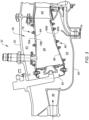
- the diffuser OD flow 142 enters the diffuser OD flow path 62 and the diffuser ID flow 144 enters the diffuser ID flow path 64.
- the air entering the combustor 35, the diffuser OD flow path 62, and the diffuser ID flow path 64 very likely contains entrained particulate matter; i.e., "dirty air”.
- all or a portion of the dirty air entering the diffuser OD flow path 62 will enter the particle separator 58A disposed within the diffuser OD flow path 62, and all or a portion of the dirty air entering the diffuser ID flow path 64 will enter the particle separator 58B disposed within the diffuser ID flow path 64.
- dirty air flow is drawn in through inlet apertures 106 disposed adjacent the exterior wall 114 of the separator 58A.
- the separator 58A is configured to direct the air flow spirally toward the exit apertures 108.
- This separator 58A embodiment leverages the fact that the inlet airflow is adjacent the exterior wall 114 by electrostatically charging all or portions of the exterior wall 114 (or electrically conductive panels 136 attached to the exterior wall 114). Hence, as the airflow passes within the separator 58A in close proximity to the exterior wall 114, charged particles entrained within the air will be attracted to the electrostatically charged exterior wall 114.
- the present disclosure system may be controlled to continuously, intermittently, or selectively electrostatically charge all or portions of the exterior wall 114.
- the collection pockets 110 are disposed adjacent to the exterior wall 114, positioned to capture and collect particulate matter.
- the mechanism 96 (see FIGS. 2 and 10 ) for producing an electrostatically charged surface may be controlled to be in an on mode or an off mode. When the mechanism 96 is in an on mode, particles not adhered to the charged surface but drawn towards the charged surface may be captured within the collection pockets 110. When the mechanism 96 is in an off mode, particles may release from the charged surface and be drawn into the collection pockets 110 as they travel with the air flow.
- the spiral configuration of the helical dividers 100 assist in the desired outward particle movement by causing centrifugal forces to act on the particles.
- the air flow that continues to travel axially and spirally within the particle separator 58A will be "cleaner" air relative to the air that entered the particle separator 58A.
- the exit apertures 108 of the particle separator 58A may be configured to allow the clean air to exit the particle separator 58A along the axial length of the separator 58A (adjacent the combustor 35 - i.e., adjacent the outer combustor wall assembly 78 as shown in FIG. 3 ) and/or at the aft end 122 of the separator 58A.
- dirty air flow is drawn in through inlet apertures 106 disposed adjacent the interior wall 116 of the separator 58B.
- the separator 58B is configured to direct the air flow spirally toward the exit apertures 108.
- This separator 58B embodiment leverages the fact that the inlet airflow is adjacent the interior wall 116 by electrostatically charging all or portions of the interior wall 116 (or electrically conductive panels 136 attached to the interior wall 116). Hence, as the air flow passes within the separator 58B in close proximity to the interior wall 116, charged particles entrained within the air will be attracted to the electrostatically charged interior wall 116.
- the present disclosure system may be controlled to continuously, intermittently, or selectively electrostatically charge all or portions of the interior wall 116.
- the collection pockets 110 are disposed adjacent to the interior wall 116, positioned to capture and collect particulate matter.
- the mechanism 96 (see FIGS. 2 and 10 ) for producing an electrostatically charged surface may be controlled to be in an on mode or an off mode. When the mechanism 96 is in an on mode, particles not adhered to the charged surface but drawn towards the charged surface may be captured within the collection pockets 110. When the mechanism 96 is in an off mode, particles may release from the charged surface and be drawn into the collection pockets 110 as they travel with the air flow.
- the air flow that continues to travel axially and spirally within the particle separator 58B will be "cleaner" air relative to the air that entered the particle separator 58B.
- the exit apertures 108 of the particle separator 58B may be configured to allow the clean air to exit the particle separator 58B along the axial length of the separator 58B (adjacent the combustor 35 - i.e., adjacent the inner combustor wall assembly 80 as shown in FIG. 3 ) and/or at the aft end 122 of the separator 58B.
- clean air exiting the particle separator 58 disposed in the diffuser OD flow path 62 may be used to cool the combustor 35 and/or be used to cool the HPT components including, but not limited to, the first HPT stator vane stage 66, the first HPT rotor stage 68, the first HPT rotor BOAS 70, the second HPT stator vane stage 72, the second HPT rotor BOAS 76, and the like (see FIGS. 2 and 8 ).
- the clean air produced by the present disclosure particle separators 58 decreases the potential for fouling and therefore increase the likelihood of successful HPT component cooling over a greater period of time.
- small particles i.e., those having a diameter / hydraulic diameter less than fifty microns - 50 ⁇ m
- large particles i.e., those having a diameter / hydraulic diameter greater than fifty microns - 50 ⁇ m typically possess a positive charge.
- any one of these structures may describe the operations as a sequential process, many of the operations can be performed in parallel or concurrently.
- the order of the operations may be rearranged.
- a process may correspond to a method, a function, a procedure, a subroutine, a subprogram, etc.
Landscapes
- Engineering & Computer Science (AREA)
- Chemical & Material Sciences (AREA)
- Combustion & Propulsion (AREA)
- Mechanical Engineering (AREA)
- General Engineering & Computer Science (AREA)
- Structures Of Non-Positive Displacement Pumps (AREA)
- Electrostatic Separation (AREA)
Applications Claiming Priority (1)
| Application Number | Priority Date | Filing Date | Title |
|---|---|---|---|
| US202363542452P | 2023-10-04 | 2023-10-04 |
Publications (2)
| Publication Number | Publication Date |
|---|---|
| EP4534820A2 true EP4534820A2 (de) | 2025-04-09 |
| EP4534820A3 EP4534820A3 (de) | 2025-07-09 |
Family
ID=93013701
Family Applications (1)
| Application Number | Title | Priority Date | Filing Date |
|---|---|---|---|
| EP24204826.2A Pending EP4534820A3 (de) | 2023-10-04 | 2024-10-04 | Gasturbinenmotor mit abscheidern für mitgeführte partikel |
Country Status (2)
| Country | Link |
|---|---|
| US (1) | US20260104008A1 (de) |
| EP (1) | EP4534820A3 (de) |
Family Cites Families (4)
| Publication number | Priority date | Publication date | Assignee | Title |
|---|---|---|---|---|
| US8539775B1 (en) * | 2012-03-21 | 2013-09-24 | Honeywell International Inc. | Gas turbine engines and systems and methods for removing particulate matter therefrom during operation |
| US9631554B2 (en) * | 2014-01-14 | 2017-04-25 | Honeywell International Inc. | Electrostatic charge control inlet particle separator system |
| US10695704B2 (en) * | 2016-07-20 | 2020-06-30 | General Electric Company | Multi-station debris separation system |
| GB202000870D0 (en) * | 2020-01-21 | 2020-03-04 | Rolls Royce Plc | A combustion chamber, a combustion chamber tile and a combustion chamber segment |
-
2024
- 2024-10-04 US US18/906,715 patent/US20260104008A1/en active Pending
- 2024-10-04 EP EP24204826.2A patent/EP4534820A3/de active Pending
Also Published As
| Publication number | Publication date |
|---|---|
| US20260104008A1 (en) | 2026-04-16 |
| EP4534820A3 (de) | 2025-07-09 |
Similar Documents
| Publication | Publication Date | Title |
|---|---|---|
| EP2927504B1 (de) | Motorsysteme und verfahren zur entfernung von partikeln aus turbinenluft | |
| US10036319B2 (en) | Separator assembly for a gas turbine engine | |
| US8539775B1 (en) | Gas turbine engines and systems and methods for removing particulate matter therefrom during operation | |
| US10167725B2 (en) | Engine component for a turbine engine | |
| US9810079B2 (en) | Cyclonic dirt separating turbine accelerator | |
| US9631554B2 (en) | Electrostatic charge control inlet particle separator system | |
| JP6925690B2 (ja) | タービンエンジンのための粒子分離装置組立体 | |
| US10830138B2 (en) | Fine debris multi-stage separation system | |
| JP2017082792A (ja) | タービンエンジン用サイクロン分離器 | |
| CN109139261B (zh) | 涡轮机械及其所用的颗粒分离器系统和移除颗粒的方法 | |
| BR102016025661A2 (pt) | motor de turbina e superfície de controle | |
| EP3536930B1 (de) | Trägheitspartikelabscheider mit adaptiver krümmung | |
| EP3085892A1 (de) | Fanschaufel, zugehöriges gasturbinentriebwerk und herstellungsverfahren | |
| EP4534820A2 (de) | Gasturbinenmotor mit abscheidern für mitgeführte partikel | |
| EP3546724B1 (de) | Trägheitspartikelabscheider mit adaptivem bereich | |
| EP4534824A2 (de) | Gasturbinenmotor mit mitgeführtem teilchenabscheider | |
| EP4534911A1 (de) | Gasturbinenmotor mit abscheidern für mitgeführte partikel | |
| EP4534809A1 (de) | Gasturbinenmotor mit mitgeführten teilchenagglomeratoren und verfahren | |
| US12584442B2 (en) | Gas turbine engine with entrained particle separation system |
Legal Events
| Date | Code | Title | Description |
|---|---|---|---|
| PUAI | Public reference made under article 153(3) epc to a published international application that has entered the european phase |
Free format text: ORIGINAL CODE: 0009012 |
|
| STAA | Information on the status of an ep patent application or granted ep patent |
Free format text: STATUS: THE APPLICATION HAS BEEN PUBLISHED |
|
| AK | Designated contracting states |
Kind code of ref document: A2 Designated state(s): AL AT BE BG CH CY CZ DE DK EE ES FI FR GB GR HR HU IE IS IT LI LT LU LV MC ME MK MT NL NO PL PT RO RS SE SI SK SM TR |
|
| PUAL | Search report despatched |
Free format text: ORIGINAL CODE: 0009013 |
|
| AK | Designated contracting states |
Kind code of ref document: A3 Designated state(s): AL AT BE BG CH CY CZ DE DK EE ES FI FR GB GR HR HU IE IS IT LI LT LU LV MC ME MK MT NL NO PL PT RO RS SE SI SK SM TR |
|
| RIC1 | Information provided on ipc code assigned before grant |
Ipc: F02C 7/30 20060101ALI20250530BHEP Ipc: F02C 7/052 20060101ALI20250530BHEP Ipc: F02C 3/14 20060101AFI20250530BHEP |
|
| STAA | Information on the status of an ep patent application or granted ep patent |
Free format text: STATUS: REQUEST FOR EXAMINATION WAS MADE |
|
| 17P | Request for examination filed |
Effective date: 20260109 |