EP4534817A1 - Work vehicle - Google Patents
Work vehicle Download PDFInfo
- Publication number
- EP4534817A1 EP4534817A1 EP24200407.5A EP24200407A EP4534817A1 EP 4534817 A1 EP4534817 A1 EP 4534817A1 EP 24200407 A EP24200407 A EP 24200407A EP 4534817 A1 EP4534817 A1 EP 4534817A1
- Authority
- EP
- European Patent Office
- Prior art keywords
- muffler
- vibration
- longitudinal direction
- vibration mount
- bracket
- Prior art date
- Legal status (The legal status is an assumption and is not a legal conclusion. Google has not performed a legal analysis and makes no representation as to the accuracy of the status listed.)
- Granted
Links
Images


Classifications
-
- B—PERFORMING OPERATIONS; TRANSPORTING
- B60—VEHICLES IN GENERAL
- B60K—ARRANGEMENT OR MOUNTING OF PROPULSION UNITS OR OF TRANSMISSIONS IN VEHICLES; ARRANGEMENT OR MOUNTING OF PLURAL DIVERSE PRIME-MOVERS IN VEHICLES; AUXILIARY DRIVES FOR VEHICLES; INSTRUMENTATION OR DASHBOARDS FOR VEHICLES; ARRANGEMENTS IN CONNECTION WITH COOLING, AIR INTAKE, GAS EXHAUST OR FUEL SUPPLY OF PROPULSION UNITS IN VEHICLES
- B60K13/00—Arrangement in connection with combustion air intake or gas exhaust of propulsion units
- B60K13/04—Arrangement in connection with combustion air intake or gas exhaust of propulsion units concerning exhaust
-
- F—MECHANICAL ENGINEERING; LIGHTING; HEATING; WEAPONS; BLASTING
- F01—MACHINES OR ENGINES IN GENERAL; ENGINE PLANTS IN GENERAL; STEAM ENGINES
- F01N—GAS-FLOW SILENCERS OR EXHAUST APPARATUS FOR MACHINES OR ENGINES IN GENERAL; GAS-FLOW SILENCERS OR EXHAUST APPARATUS FOR INTERNAL-COMBUSTION ENGINES
- F01N1/00—Silencing apparatus characterised by method of silencing
-
- F—MECHANICAL ENGINEERING; LIGHTING; HEATING; WEAPONS; BLASTING
- F01—MACHINES OR ENGINES IN GENERAL; ENGINE PLANTS IN GENERAL; STEAM ENGINES
- F01N—GAS-FLOW SILENCERS OR EXHAUST APPARATUS FOR MACHINES OR ENGINES IN GENERAL; GAS-FLOW SILENCERS OR EXHAUST APPARATUS FOR INTERNAL-COMBUSTION ENGINES
- F01N13/00—Exhaust or silencing apparatus characterised by constructional features
- F01N13/18—Construction facilitating manufacture, assembly, or disassembly
- F01N13/1805—Fixing exhaust manifolds, exhaust pipes or pipe sections to each other, to engine or to vehicle body
- F01N13/1811—Fixing exhaust manifolds, exhaust pipes or pipe sections to each other, to engine or to vehicle body with means permitting relative movement, e.g. compensation of thermal expansion or vibration
- F01N13/1822—Fixing exhaust manifolds, exhaust pipes or pipe sections to each other, to engine or to vehicle body with means permitting relative movement, e.g. compensation of thermal expansion or vibration for fixing exhaust pipes or devices to vehicle body
-
- F—MECHANICAL ENGINEERING; LIGHTING; HEATING; WEAPONS; BLASTING
- F01—MACHINES OR ENGINES IN GENERAL; ENGINE PLANTS IN GENERAL; STEAM ENGINES
- F01N—GAS-FLOW SILENCERS OR EXHAUST APPARATUS FOR MACHINES OR ENGINES IN GENERAL; GAS-FLOW SILENCERS OR EXHAUST APPARATUS FOR INTERNAL-COMBUSTION ENGINES
- F01N13/00—Exhaust or silencing apparatus characterised by constructional features
- F01N13/18—Construction facilitating manufacture, assembly, or disassembly
- F01N13/1838—Construction facilitating manufacture, assembly, or disassembly characterised by the type of connection between parts of exhaust or silencing apparatus, e.g. between housing and tubes, between tubes and baffles
- F01N13/1844—Mechanical joints
-
- B—PERFORMING OPERATIONS; TRANSPORTING
- B62—LAND VEHICLES FOR TRAVELLING OTHERWISE THAN ON RAILS
- B62D—MOTOR VEHICLES; TRAILERS
- B62D63/00—Motor vehicles or trailers not otherwise provided for
- B62D63/02—Motor vehicles
- B62D63/04—Component parts or accessories
-
- F—MECHANICAL ENGINEERING; LIGHTING; HEATING; WEAPONS; BLASTING
- F01—MACHINES OR ENGINES IN GENERAL; ENGINE PLANTS IN GENERAL; STEAM ENGINES
- F01N—GAS-FLOW SILENCERS OR EXHAUST APPARATUS FOR MACHINES OR ENGINES IN GENERAL; GAS-FLOW SILENCERS OR EXHAUST APPARATUS FOR INTERNAL-COMBUSTION ENGINES
- F01N2590/00—Exhaust or silencing apparatus adapted to particular use, e.g. for military applications, airplanes, submarines
- F01N2590/08—Exhaust or silencing apparatus adapted to particular use, e.g. for military applications, airplanes, submarines for heavy duty applications, e.g. trucks, buses, tractors, locomotives
Definitions
- An object of the present invention is to provide a configuration for a work vehicle where a muffler is attached to an attachment target via an anti-vibration mount, the configuration allowing the muffler to be properly attached to the attachment target with a small number of anti-vibration mounts.
- a work vehicle of the present invention includes an engine, an exhaust pipe extending from the engine, and a first anti-vibration mount and a second anti-vibration mount with which the muffler is attached to an attachment target while the muffler is oriented with a longitudinal direction of the muffler extending along a horizontal plane, wherein the first anti-vibration mount is located on a portion of the muffler on one side of the muffler in the longitudinal direction and on a portion of the muffler on one side of the muffler in an up-down direction, and the second anti-vibration mount is located on a portion of the muffler on another side of the muffler in the longitudinal direction and on a portion of the muffler on another side of the muffler in the up-down direction.
- the muffler is attached to the attachment target with the first anti-vibration mount and the second anti-vibration mount while the muffler is oriented with its longitudinal direction extending along a horizontal plane (for example, while the muffler is oriented with its longitudinal direction extending along a front-rear direction or a left-right direction).
- the first anti-vibration mount may be located on a lower front portion of the muffler, and the second anti-vibration mount is located on an upper rear portion of the muffler.
- the first and second anti-vibration mounts when viewed in a direction along a horizontal plane and orthogonal to the longitudinal direction of the muffler, are positioned on a diagonal line of the muffler, away from each other.
- the exhaust pipe is connected to the portion of the muffler on the one side of the muffler in the longitudinal direction and to the portion of the muffler on the one side of the muffler in the up-down direction.
- the exhaust pipe is connected to a portion of the muffler near the first anti-vibration mount.
- the work vehicle includes a spherical joint connecting the exhaust pipe and the muffler to each other.
- the position of the exhaust pipe may be changed according to changes in engine specifications, model changes, or the like.
- the first and second anti-vibration mounts include the anti-vibration rubbers having the respective openings, and the bases on which the respective support members are located, and the muffler is supported by the first and second anti-vibration mounts as a result of the support members being inserted into the openings of the anti-vibration rubbers.
- the openings of the anti-vibration rubbers and the support members are oriented in the identical direction, and this allows the muffler and the first and second anti-vibration mounts to be assembled in the same manner and therefore can improve the assemblability of the muffler and the first and second anti-vibration mounts.
- the position change is accommodated by the support members moving along the openings of the anti-vibration rubbers (or by the anti-vibration rubbers moving along the support members).
- the anti-vibration rubber is located on the attachment target, and the base is located on the muffler.
- the anti-vibration rubber is easily positioned farther away from the muffler than the base and the support member. This can suppress the transfer of heat from the muffler to the anti-vibration rubber, thereby improving the durability of the anti-vibration rubber.
- leg portions of the base have the openings, heat transfer paths in the leg portions of the base that transfer heat from the other one of the muffler and the attachment target are narrowed, which is advantageous for suppressing the transfer of heat from the base and the support member to the anti-vibration rubber and hence for improving the durability of the anti-vibration rubber.
- the base is made of, for example, stainless steel (SUS), which has low thermal conductivity, it is more advantageous for suppressing the transfer of heat from the base and the support member to the anti-vibration rubber.
- SUS stainless steel
- the attachment member is joined to the bracket, and the anti-vibration rubber is attached to the bracket by the attachment member.
- the reduction in the contact area between the anti-vibration rubber and the bracket is advantageous for suppressing the transfer of heat from one of the muffler and the attachment target to the anti-vibration rubber and hence for improving the durability of the anti-vibration rubber.
- the attachment member has a pair of the engagement portions, one of the engagement portions is configured to engage with one of laterally adjacent portions of one of the protrusions of the opening of the bracket, and the other one of the engagement portions is configured to engage with the other one of the laterally adjacent portions of the protrusion of the opening of the bracket.
- one of the protrusions of the opening of the bracket is located between the pair of engagement portions of the attachment member.
- the anti-vibration rubber rests on the pair of protrusions of the opening of the bracket, the anti-vibration rubber is pressed against the bracket and attached to the bracket by the attachment member in a well-balanced manner.
- FIGS. 1 to 6 show a utility work vehicle.
- F indicates a forward direction
- B indicates a rearward direction
- U indicates an upward direction
- D indicates a downward direction
- R indicates a rightward direction
- L indicates a leftward direction.
- An exhaust pipe 15 extends forward and leftward from an exhaust manifold at a front portion of the engine 12 and then extends rearward.
- a muffler 17 is located to the left of the transmission case 14 and extends along a left lateral surface of the transmission case 14.
- a longitudinal direction A1 (see FIG. 3 ) of the muffler 17 extends along the front-rear direction and the left lateral surface of the transmission case 14.
- the muffler 17 has a cylindrical main body 17a and disc-shaped front and rear face sections 17b and 17c, with an inlet pipe 17d on the front face section 17b and an outlet pipe 17e on the rear face section 17c.
- the second anti-vibration mount 22 is located on a rear portion of the main body 17a of the muffler 17 (corresponding to a portion on another side of the muffler 17 in the longitudinal direction A1) and on an upper portion of the main body 17a of the muffler 17 (corresponding to a portion on another side of the muffler 17 in the up-down direction A2).
- the work vehicle includes the first anti-vibration mount 21 and the second anti-vibration mount 22 with which the muffler 17 is attached to the attachment target (transmission case 14) while the muffler 17 is oriented with its longitudinal direction A1 extending along a horizontal plane.
- the first anti-vibration mount 21 is located on the portion of the muffler 17 on the one side of the muffler 17 in the longitudinal direction A1 and on the portion of the muffler 17 on the one side of the muffler 17 in the up-down direction A2.
- the connecting portion between the exhaust pipe 15 and the muffler 17, the first anti-vibration mount 21, and the second anti-vibration mount 22 are located at the following three positions, with one of these three components at each of the three positions: the position of the imaginary vertical line B1 passing through the center of the muffler 17 when viewed in the longitudinal direction A1 of the muffler 17, and the positions on the one side and the other side, respectively, relative to the vertical line B1, in the direction extending along a horizontal plane.
- the first anti-vibration mount 21 When viewed in the longitudinal direction A1 of the muffler 17, the first anti-vibration mount 21 is located at the position of the vertical line B1.
- the first anti-vibration mount 21 and the second anti-vibration mount 22 each have an anti-vibration rubber 23, a base 24, a support member 25, a bracket 26, and an attachment member 27.
- the bracket 26 is bolted to a left lateral side portion of the transmission case 14 (see FIG. 5 ).
- the bracket 26 has an H-shaped opening 26c, with protrusions 26a at one end and the other end, respectively, of the opening 26c of the bracket 26 in the left-right direction.
- the protrusions 26a face each other in such a manner as to protrude toward the center of the opening 26c of the bracket 26.
- a pair of recesses 26b are located next to one of the protrusions 26a on both lateral sides thereof.
- the base 24 is formed from a plate material bent into a W-shape and includes a pair of leg portions 24a and a recess 24b that is connected to and extends between respective ends of the pair of leg portions 24a. Each of the pair of leg portions 24a has an elongated opening 24c.
- the support member 25 is round rod-shaped and is placed in and attached to the recess 24b of the base 24.
- each leg portion 24a of the base 24 is attached to the muffler 17. Accordingly, the recess 24b of the base 24 is located between the respective ends, opposite to the muffler 17, of the pair of leg portions 24a of the base 24, and the support member 25 is located away from the muffler 17.
- the leg portions 24a of the base 24 are attached to the front portion of the main body 17a of the muffler 17 and to the lower portion of the main body 17a of the muffler 17.
- the support member 25 extends from the base 24 toward the front face section 17b of the muffler 17 along the longitudinal direction A1 of the muffler 17.
- the engagement portions 27b of the attachment member 27 are inserted into and engaged with the recesses 26b of the bracket 26, and the joining portion 27a of the attachment member 27 is joined to the bracket 26 with a bolt 19.
- the anti-vibration rubber 23 is pressed against the protrusions 26a of the bracket 26 by the attachment member 27 and thereby attached to the bracket 26.
- the support member 25 is inserted into the opening 23a of the anti-vibration rubber 23 from the rear of the anti-vibration rubber 23 and projects forward from the opening 23a of the anti-vibration rubber 23.
- the support member 25 is inserted into the opening 23a of the anti-vibration rubber 23 from the front of the anti-vibration rubber 23 and projects rearward from the opening 23a of the anti-vibration rubber 23.
- the operator moves the muffler 17 forward from a position to the rear of the first anti-vibration mount 21 and, in the first anti-vibration mount 21, inserts the support member 25 into the opening 23a of the anti-vibration rubber 23 from the rear.
- the operator brings the portion of the inlet pipe 17d of the muffler 17 that is located within the spherical joint 16 into contact with the portion of the exhaust pipe 15 that is located within the spherical joint 16 and attaches the springs 18 between the attachment portions 15a of the exhaust pipe 15 and the corresponding attachment portions 17f of the muffler 17.
- the first anti-vibration mount 21 and the second anti-vibration mount 22 each include the anti-vibration rubber 23 that is located on one of the muffler 17 and the attachment target (transmission case 14) and has the opening 23a, the base 24 located on the other one of the muffler 17 and the attachment target (transmission case 14), and the support member 25 located on the base 24.
- the anti-vibration rubber 23 is located on the attachment target (transmission case 14), and the base 24 is located on the muffler 17.
- the support member 25 of the first anti-vibration mount 21 and the support member 25 of the second anti-vibration mount 22 extend in opposite directions to each other from the respective bases 24.
- the support members 25 When the support members 25 are inserted into the openings 23a of the anti-vibration rubbers 23, the base 24 of the first anti-vibration mount 21 and the base 24 of the second anti-vibration mount 22 are positioned on opposite sides relative to the anti-vibration rubbers 23.
- the base 24 has the pair of leg portions 24a attached to the other one of the muffler 17 and the attachment target (transmission case 14), and the recess 24b located between the respective ends, opposite to the other one of the muffler 17 and the attachment target (transmission case 14), of the pair of leg portions 24a and bent toward the other one of the muffler 17 and the attachment target (transmission case 14).
- the attachment member 27 has the engagement portions 27b located at one end of the attachment member 27 and configured to engage with the bracket 26 and the joining portion 27a located at the other end of the attachment member 27 and configured to be joined to the bracket 26 with the bolt 19.
- a configuration may be adopted in which, in both of the first and second anti-vibration mounts 21 and 22, the support member 25 extends from the base 24 toward the rear face section 17c of the muffler 17 along the longitudinal direction A1 of the muffler 17.
- a configuration may be adopted in which, when viewed in the longitudinal direction A1 of the muffler 17, the inlet pipe 17d of the muffler 17 (the spherical joint 16 and the exhaust pipe 15) is located at the position of the vertical line B1, the first anti-vibration mount 21 is located to the left (on the side that is far from the attachment target) of the vertical line B1, and the second anti-vibration mount 22 is located to the right (on the side that is near the attachment target) of the vertical line B1.
- a configuration may be adopted in which, in the first and second anti-vibration mounts 21 and 22, the openings 23a of the anti-vibration rubbers 23 and the support members 25 are oriented in a direction (left-right direction) that is orthogonal to the longitudinal direction A1 of the muffler 17.
- a configuration may be adopted in which the engine 12 is configured as a longitudinally mounted type with the crankshaft (not shown) oriented in the front-rear direction, and the belt-driven type continuously variable transmission 13 is replaced with a hydrostatic continuously variable transmission 13.
- the engine 12 a frame (not shown) included in the body 3, or the like may be set as the attachment target.
Landscapes
- Engineering & Computer Science (AREA)
- Chemical & Material Sciences (AREA)
- Combustion & Propulsion (AREA)
- Mechanical Engineering (AREA)
- General Engineering & Computer Science (AREA)
- Transportation (AREA)
- Cooling, Air Intake And Gas Exhaust, And Fuel Tank Arrangements In Propulsion Units (AREA)
- Exhaust Silencers (AREA)
Abstract
Description
- The present invention relates to a muffler attachment structure of a work vehicle with an engine.
- Among utility work vehicles exemplifying work vehicles with engines, there is a type of utility work vehicle in which, as disclosed in
JP 2019-155998A -
JP 2019-155998A - In order to prevent damage to the mufflers of work vehicles, it has been proposed to attach the muffler to the attachment target via an anti-vibration mount.
- An object of the present invention is to provide a configuration for a work vehicle where a muffler is attached to an attachment target via an anti-vibration mount, the configuration allowing the muffler to be properly attached to the attachment target with a small number of anti-vibration mounts.
- A work vehicle of the present invention includes an engine, an exhaust pipe extending from the engine, and a first anti-vibration mount and a second anti-vibration mount with which the muffler is attached to an attachment target while the muffler is oriented with a longitudinal direction of the muffler extending along a horizontal plane, wherein the first anti-vibration mount is located on a portion of the muffler on one side of the muffler in the longitudinal direction and on a portion of the muffler on one side of the muffler in an up-down direction, and the second anti-vibration mount is located on a portion of the muffler on another side of the muffler in the longitudinal direction and on a portion of the muffler on another side of the muffler in the up-down direction.
- According to the present invention, the muffler is attached to the attachment target with the first anti-vibration mount and the second anti-vibration mount while the muffler is oriented with its longitudinal direction extending along a horizontal plane (for example, while the muffler is oriented with its longitudinal direction extending along a front-rear direction or a left-right direction).
- For example, if the longitudinal direction of the muffler extends along the front-rear direction, the first anti-vibration mount may be located on a lower front portion of the muffler, and the second anti-vibration mount is located on an upper rear portion of the muffler.
- Alternatively, the first anti-vibration mount may be located on an upper front portion of the muffler, and the second anti-vibration mount is located on a lower rear portion of the muffler.
- Alternatively, the first anti-vibration mount may be located on the lower rear portion of the muffler, and the second anti-vibration mount is located on the upper front portion of the muffler.
- Alternatively, the first anti-vibration mount may be located on the upper rear portion of the muffler, and the second anti-vibration mount is located on the lower rear portion of the muffler.
- According to the present invention, when viewed in a direction along a horizontal plane and orthogonal to the longitudinal direction of the muffler, the first and second anti-vibration mounts are positioned on a diagonal line of the muffler, away from each other.
- Thus, when the muffler is attached to the attachment target with the first and second anti-vibration mounts, vibrations transmitted to the muffler from the attachment target are appropriately absorbed, even if the muffler is attached with a small number of first and second anti-vibration mounts, and damage to the muffler caused by vibrations can be prevented.
- In the present invention, it is preferable that the exhaust pipe is connected to the portion of the muffler on the one side of the muffler in the longitudinal direction and to the portion of the muffler on the one side of the muffler in the up-down direction.
- According to the present invention, the exhaust pipe is connected to a portion of the muffler near the first anti-vibration mount.
- This allows vibrations transmitted to the muffler from the exhaust pipe to be appropriately absorbed by the first anti-vibration mount and is therefore advantageous for preventing damage to the muffler caused by vibrations.
- In the present invention, it is preferable that, when viewed in the longitudinal direction of the muffler, a connecting portion between the exhaust pipe and the muffler, the first anti-vibration mount, and the second anti-vibration mount are located at three positions, with one at each of the three positions, the three positions being a position of an imaginary vertical line passing through a center of the muffler when viewed in the longitudinal direction of the muffler, and positions on one side and another side, respectively, relative to the vertical line, in a direction extending along a horizontal plane.
- According to the present invention, when viewed in the longitudinal direction of the muffler, the three components, that is, the connecting portion between the exhaust pipe and the muffler, the first anti-vibration mount, and the second anti-vibration mount are respectively located at the position of the vertical line and the positions on the one side and the other side relative to the vertical line in the direction extending along a horizontal plane, with one component assigned to each of these three positions.
- This is advantageous for preventing damage to the muffler caused by vibrations, because the three components, that is, the connecting portion between the exhaust pipe and the muffler, the first anti-vibration mount, and the second anti-vibration mount are located at dispersed positions when viewed in the longitudinal direction of the muffler, and vibrations transmitted to the muffler from the exhaust pipe are appropriately absorbed by the first anti-vibration mount.
- In the present invention, it is preferable that the exhaust pipe is connected to the portion of the muffler on the one side of the muffler in the longitudinal direction and to the portion of the muffler on the one side of the muffler in the up-down direction; when viewed in the longitudinal direction of the muffler, the connecting portion between the exhaust pipe and the muffler is located on the one side relative to the vertical line in the direction extending along a horizontal plane; when viewed in the longitudinal direction of the muffler, the first anti-vibration mount is located at the position of the vertical line; and when viewed in the longitudinal direction of the muffler, the second anti-vibration mount is located on the other side relative to the vertical line in the direction extending along a horizontal plane.
- According to the present invention, the exhaust pipe is connected to a portion of the muffler near the first anti-vibration mount.
- This allows vibrations transmitted to the muffler from the exhaust pipe to be appropriately absorbed by the first anti-vibration mount and is therefore advantageous in preventing damage to the muffler caused by vibrations.
- According to the present invention, in the above-described state, when viewed in the longitudinal direction of the muffler, the connecting portion between the exhaust pipe and the muffler is located on the one side relative to the vertical line in the direction extending along a horizontal plane, and the first anti-vibration mount is located at the position of the vertical line.
- This is advantageous for preventing damage to the muffler caused by vibrations, because the connecting portion between the exhaust pipe and the muffler and the first anti-vibration mount are located closer to each other than when the connecting portion between the exhaust pipe and the muffler and the first anti-vibration mount are located on the one side and the other side, respectively, relative to the vertical line in the horizontal direction.
- In the present invention, it is preferable that the muffler is positioned laterally to the attachment target while the muffler is oriented with the longitudinal direction of the muffler extending along the attachment target; when viewed in the longitudinal direction of the muffler, the connecting portion between the exhaust pipe and the muffler is located on a side that is far from the attachment target, relative to the vertical line, in the direction extending along a horizontal plane; when viewed in the longitudinal direction of the muffler, one of the first anti-vibration mount and the second anti-vibration mount is located at the position of the vertical line; and when viewed in the longitudinal direction of the muffler, the other one of the first anti-vibration mount and the second anti-vibration mount is located on a side that is near the attachment target, relative to the vertical line, in the direction extending along a horizontal plane.
- In work vehicles, the muffler may be positioned laterally to the attachment target while the muffler is oriented with the longitudinal direction of the muffler extending along the attachment target.
- According to the present invention, when viewed in the longitudinal direction of the muffler, the connecting portion between the exhaust pipe and the muffler is located on the side that is far from the attachment target, relative to the vertical line, in the direction extending along a horizontal plane, and this ensures that the exhaust pipe is easily positioned away from the attachment target.
- Consequently, this reduces the likelihood of the exhaust pipe and the attachment target coming into contact due to vibrations and the like, and is therefore advantageous for preventing damage to the muffler caused by vibrations.
- According to the present invention, when viewed in the longitudinal direction of the muffler, the first anti-vibration mount and the second anti-vibration mount are located at the position of the vertical line and the position on the side that is near the attachment target, relative to the vertical line, in the direction extending along a horizontal plane, and this ensures that the first and second anti-vibration mounts are easily positioned close to the attachment target.
- Consequently, this allows the first and second anti-vibration mounts to be easily configured compactly, which is advantageous for structural simplification.
- In the present invention, it is preferable that the work vehicle includes a spherical joint connecting the exhaust pipe and the muffler to each other.
- In work vehicles, the position of the exhaust pipe may be changed according to changes in engine specifications, model changes, or the like.
- According to the present invention, the exhaust pipe and the muffler are connected to each other via the spherical joint, so that even when the position of the exhaust pipe is changed as described above, this change in the position of the exhaust pipe is accommodated by the spherical joint.
- Consequently, even when the position of the exhaust pipe is changed due to a change in engine specifications, a model change, or the like, there is no need to change the muffler according to the change in engine specifications, the model change, or the like, and this allows a muffler to be used for engines with various specifications or of various types, which is advantageous for reducing the number of components.
- In the present invention, it is preferable that the first anti-vibration mount and the second anti-vibration mount each include an anti-vibration rubber that is located on one of the muffler and the attachment target and has an opening, a base located on the other one of the muffler and the attachment target, and a support member located on the base, and the opening of the anti-vibration rubber and the support member are oriented in an identical direction, and the support member is in the opening of the anti-vibration rubber.
- According to the present invention, the first and second anti-vibration mounts include the anti-vibration rubbers having the respective openings, and the bases on which the respective support members are located, and the muffler is supported by the first and second anti-vibration mounts as a result of the support members being inserted into the openings of the anti-vibration rubbers.
- In this case, in the first and second anti-vibration mounts, the openings of the anti-vibration rubbers and the support members are oriented in the identical direction, and this allows the muffler and the first and second anti-vibration mounts to be assembled in the same manner and therefore can improve the assemblability of the muffler and the first and second anti-vibration mounts.
- According to the present invention, when the muffler is supported by the first and second anti-vibration mounts as a result of the support members being inserted into the openings of the anti-vibration rubbers, the support members are movable along the openings of the anti-vibration rubbers (or the anti-vibration rubbers are movable along the support members).
- Consequently, even if stress due to an assembly error or the like begins to occur during the assembly of the muffler and the first and second anti-vibration mounts, the stress is released as the support members move along the openings of the anti-vibration rubbers (or as the anti-vibration rubbers move along the support members). Since stress due to an assembly error or the like is released, residual stress is unlikely to occur, and therefore, damage to the muffler or the like caused by residual stress can be prevented.
- According to the present invention, when the position of the exhaust pipe is changed due to a change in engine specifications, a model change, or the like, if this position change is along the direction of the openings of the anti-vibration rubbers and the support members, the position change is accommodated by the support members moving along the openings of the anti-vibration rubbers (or by the anti-vibration rubbers moving along the support members).
- This eliminates the need to change the muffler according to a change in engine specifications, a model change, or the like, and therefore allows a muffler to be used for engines with various specifications or of various types, which is advantageous for structural simplification.
- In the present invention, it is preferable that the opening of the anti-vibration rubber and the support member are oriented in the longitudinal direction of the muffler.
- According to the present invention, in the first and second anti-vibration mounts, the openings of the anti-vibration rubbers and the support members are oriented in the longitudinal direction of the muffler. This is advantageous for improving the assemblability of the first and second anti-vibration mounts.
- In the present invention, it is preferable that the anti-vibration rubber is located on the attachment target, and the base is located on the muffler.
- According to the present invention, the anti-vibration rubber is easily positioned farther away from the muffler than the base and the support member. This can suppress the transfer of heat from the muffler to the anti-vibration rubber, thereby improving the durability of the anti-vibration rubber.
- In the present invention, it is preferable that the support member of the first anti-vibration mount and the support member of the second anti-vibration mount extend in opposite directions to each other from the respective bases, and when the support members are in the openings of the anti-vibration rubbers, the base of the first anti-vibration mount and the base of the second anti-vibration mount are positioned on opposite sides relative to the anti-vibration rubbers.
- According to the present invention, when the muffler moves in one direction or the opposite direction along the openings of the anti-vibration rubbers and the support members, the movement of the muffler is stopped by the anti-vibration rubber and the base abutting each other in the first anti-vibration mount (or in the second anti-vibration mount).
- This ensures that, if the support members are movable along the openings of the anti-vibration rubbers (or if the anti-vibration rubbers are movable along the support members),
the muffler does not move more than necessary. In this case, the need for a dedicated stopper that stops the movement of the muffler is eliminated by effectively using the configuration of the first and second anti-vibration mounts, which is advantageous for structural simplification. - In the present invention, it is preferable that the base has a pair of leg portions attached to the other one of the muffler and the attachment target, and a recess located between respective ends, opposite to the other one of the muffler and the attachment target, of the pair of leg portions and bent toward the other one of the muffler and the attachment target, and the support member is attached to the recess.
- According to the present invention, since the base has a bent shape due to having the pair of leg portions and the recess, the strength of the base can be increased. Since the support member is attached to the recess of the base in such a manner as to be inserted into the recess, the support member can be smoothly attached to the base, and the support member serves as a reinforcing member for the base. Accordingly, the overall strength of the base and the support member can be increased.
- According to the present invention, the pair of leg portions of the base are attached to the other one of the muffler and the attachment target, and the contact area between the base and the other one of the muffler and the attachment target is small.
- This can suppress the transfer of heat from the other one of the muffler and the attachment target to the base and the support member, and from the support member to the anti-vibration rubber, thereby improving the durability of the anti-vibration rubber.
- In the present invention, it is preferable that the leg portions each have an opening.
- According to the present invention, since the leg portions of the base have the openings, a weight reduction of the base can be achieved.
- According to the present invention, since the leg portions of the base have the openings, heat transfer paths in the leg portions of the base that transfer heat from the other one of the muffler and the attachment target are narrowed, which is advantageous for suppressing the transfer of heat from the base and the support member to the anti-vibration rubber and hence for improving the durability of the anti-vibration rubber.
- When the heat transfer paths in the leg portions of the base are narrowed by the leg portions of the base having openings, if the base is made of, for example, stainless steel (SUS), which has low thermal conductivity, it is more advantageous for suppressing the transfer of heat from the base and the support member to the anti-vibration rubber.
- In the present invention, it is preferable that the work vehicle includes a bracket attached to the one of the muffler and the attachment target; and an attachment member configured to press the anti-vibration rubber against the bracket to attach the anti-vibration rubber to the bracket, wherein the attachment member has an engagement portion located at one end of the attachment member and configured to engage with the bracket, and a joining portion located at another end of the attachment member and configured to be joined to the bracket with a bolt.
- According to the present invention, when the anti-vibration rubber is located on one of the muffler and the attachment target, the work vehicle includes the bracket attached to the one of the muffler and the attachment target, and the attachment member configured to press the anti-vibration rubber against the bracket to attach the anti-vibration rubber to the bracket.
- In the above configuration, according to the present invention, as a result of the engagement portion of the attachment member being engaged with the bracket and the joining portion of the attachment member being bolted to the bracket, the attachment member is joined to the bracket, and the anti-vibration rubber is attached to the bracket by the attachment member.
- This reduces the number of bolts joining the attachment member to the bracket, and can therefore simplify the structure for joining the attachment member to the bracket.
- In the present invention, it is preferable that the bracket has an opening, a pair of protrusions are located at one end and another end of the opening of the bracket and protrude toward a center of the opening of the bracket, and the anti-vibration rubber rests on the protrusions and is attached to the bracket by being pressed against the bracket by the attachment member.
- According to the present invention, since the anti-vibration rubber is attached to the bracket while resting on the pair of protrusions of the opening of the bracket, the contact area between the anti-vibration rubber and the bracket can be reduced.
- The reduction in the contact area between the anti-vibration rubber and the bracket is advantageous for suppressing the transfer of heat from one of the muffler and the attachment target to the anti-vibration rubber and hence for improving the durability of the anti-vibration rubber.
- In the present invention, it is preferable that the attachment member has a pair of the engagement portions, one of the engagement portions is configured to engage with one of laterally adjacent portions of one of the protrusions of the opening of the bracket, and the other one of the engagement portions is configured to engage with the other one of the laterally adjacent portions of the protrusion of the opening of the bracket.
- According to the present invention, when the attachment member has the pair of engagement portions, one of the protrusions of the opening of the bracket is located between the pair of engagement portions of the attachment member.
- Thus, when the anti-vibration rubber rests on the pair of protrusions of the opening of the bracket, the anti-vibration rubber is pressed against the bracket and attached to the bracket by the attachment member in a well-balanced manner.
-
-
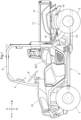
FIG. 1 is a left side view of a work vehicle. -
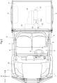
FIG. 2 is a plan view of the work vehicle. -
FIG. 3 is a left side view of an area surrounding and encompassing a muffler, a first anti-vibration mount, and a second anti-vibration mount. -
FIG. 4 is a plan view of the area surrounding and encompassing the muffler, the first anti-vibration mount, and the second anti-vibration mount. -
FIG. 5 is a front view of the area surrounding and encompassing the muffler, the first anti-vibration mount, and the second anti-vibration mount. -
FIG. 6 is an exploded perspective view of the first anti-vibration mount and the second anti-vibration mount. -
FIGS. 1 to 6 show a utility work vehicle. InFIGS. 1 to 6 , F indicates a forward direction, B indicates a rearward direction, U indicates an upward direction, D indicates a downward direction, R indicates a rightward direction, and L indicates a leftward direction. - As shown in
FIGS. 1 and2 , right and leftfront wheels 1 are located at the front, and right and leftrear wheels 2 are located at the rear of abody 3 of the work vehicle. Acab section 4 for a driver and an operator to sit is located at a portion of thebody 3 between thefront wheels 1 and therear wheels 2, and is surrounded by a roll-over protective structure (ROPS)frame 5. Thecab section 4 includes adriver seat 6, apassenger seat 7, afloor 8, asteering wheel 9 for steering thefront wheels 1, and so on. - A
hood 10 is located forward of thecab section 4, and acargo bed 11 is located rearward of thecab section 4. Thecargo bed 11 can be raised and lowered between a use position indicated by solid lines inFIG. 1 and a dump position in which a front portion of thecargo bed 11 is raised with a lower rear portion of thecargo bed 11 as a support point. - An
engine 12, a continuouslyvariable transmission 13, and a transmission case 14 (corresponding to an attachment target) are located in a rear part of thebody 3. The continuouslyvariable transmission 13 is of a belt-driven type. Thetransmission case 14 contains an auxiliary transmission (not shown) having three forward gears and one reverse gear, and a rear-wheel differential device (not shown). - Motive power of the
engine 12 is subjected to speed change by the continuouslyvariable transmission 13, transferred to the auxiliary transmission in thetransmission case 14 and subjected to speed change by the auxiliary transmission, and transferred from the rear-wheel differential device to therear wheels 2. Motive power diverted from between the auxiliary transmission and the rear-wheel differential device is transferred to thefront wheels 1 via transmission shafts (not shown). - As shown in
FIGS. 1 and2 , theengine 12 is of a transversely mounted type with a crankshaft (not shown) oriented in a left-right direction. Theengine 12, the continuouslyvariable transmission 13, and thetransmission case 14 are arranged along a front-rear direction in a plan view. - An
exhaust pipe 15 extends forward and leftward from an exhaust manifold at a front portion of theengine 12 and then extends rearward. Amuffler 17 is located to the left of thetransmission case 14 and extends along a left lateral surface of thetransmission case 14. A longitudinal direction A1 (seeFIG. 3 ) of themuffler 17 extends along the front-rear direction and the left lateral surface of thetransmission case 14. - As shown in
FIGS. 3 ,4 , and5 , themuffler 17 has a cylindricalmain body 17a and disc-shaped front andrear face sections inlet pipe 17d on thefront face section 17b and anoutlet pipe 17e on therear face section 17c. - The
inlet pipe 17d of themuffler 17 is connected to theexhaust pipe 15 via a spherical joint 16. Theoutlet pipe 17e of themuffler 17 extends leftward from therear face section 17c of themuffler 17. Thus, exhaust from theengine 12 is discharged through theexhaust pipe 15, the spherical joint 16, and themuffler 17 and then emitted from theoutlet pipe 17e of themuffler 17. - In the spherical joint 16, a plurality of
attachment portions 15a are located on theexhaust pipe 15, a plurality ofattachment portions 17f are located on theinlet pipe 17d of themuffler 17, and springs 18 are attached between theattachment portions 15a of theexhaust pipe 15 and thecorresponding attachment portions 17f of themuffler 17. - The biasing force of the
springs 18 presses a portion of theexhaust pipe 15 located within the spherical joint 16 and a portion of theinlet pipe 17d of themuffler 17 located within the spherical joint 16 against each other and prevents them from separating. Even if themuffler 17 is inclined in an up-down direction A2 or the left-right direction relative to the exhaust pipe 15 (or even if theexhaust pipe 15 is inclined in the up-down direction A2 or the left-right direction relative to the muffler 17), this inclination is accommodated by the spherical joint 16 and the expansion and contraction of thesprings 18. - Based on the above configuration, the work vehicle includes the
engine 12, theexhaust pipe 15 extending from theengine 12, and themuffler 17 to which theexhaust pipe 15 is connected. The work vehicle includes the spherical joint 16 connecting theexhaust pipe 15 and themuffler 17 to each other. - The
muffler 17 is positioned laterally to the attachment target (transmission case 14) while being oriented with its longitudinal direction A1 extending along the attachment target (transmission case 14). - As shown in
FIGS. 3 ,4 , and5 , themuffler 17 is attached to thetransmission case 14 via a firstanti-vibration mount 21 and a secondanti-vibration mount 22. - The first
anti-vibration mount 21 is located on a front portion of themain body 17a of the muffler 17 (corresponding to a portion on one side of themuffler 17 in the longitudinal direction A1) and on a lower portion of themain body 17a of the muffler 17 (corresponding to a portion on one side of themuffler 17 in the up-down direction A2). In this case, the longitudinal direction A1 of themuffler 17 extends along the front-rear direction (a direction extending along a horizontal plane). - The second
anti-vibration mount 22 is located on a rear portion of themain body 17a of the muffler 17 (corresponding to a portion on another side of themuffler 17 in the longitudinal direction A1) and on an upper portion of themain body 17a of the muffler 17 (corresponding to a portion on another side of themuffler 17 in the up-down direction A2). - As shown in
FIG. 5 , when viewed in the longitudinal direction A1 of themuffler 17, theinlet pipe 17d of the muffler 17 (the spherical joint 16 and the exhaust pipe 15) is located on a lower portion (corresponding to the portion on the one side of themuffler 17 in the up-down direction A2) of thefront face section 17b (corresponding to the portion on the one side of themuffler 17 in the longitudinal direction A1) of themuffler 17. - When an imaginary vertical line B1 passing through the center of the
muffler 17, when viewed in the longitudinal direction A1 of themuffler 17, is assumed, theinlet pipe 17d (corresponding to a connecting portion between theexhaust pipe 15 and the muffler 17) of themuffler 17 is located to the left (corresponding to one side in a direction extending along a horizontal plane and to a side that is far from the attachment target) of the vertical line B1. - When viewed in the longitudinal direction A1 of the
muffler 17, the firstanti-vibration mount 21 is located at the position of the vertical line B1. When viewed in the longitudinal direction A1 of themuffler 17, the secondanti-vibration mount 22 is located to the right (corresponding to another side in the direction extending along a horizontal plane and to a side that is near the attachment target) of the vertical line B1. - Based on the above configuration, the work vehicle includes the first
anti-vibration mount 21 and the secondanti-vibration mount 22 with which themuffler 17 is attached to the attachment target (transmission case 14) while themuffler 17 is oriented with its longitudinal direction A1 extending along a horizontal plane. - The first
anti-vibration mount 21 is located on the portion of themuffler 17 on the one side of themuffler 17 in the longitudinal direction A1 and on the portion of themuffler 17 on the one side of themuffler 17 in the up-down direction A2. - The second
anti-vibration mount 22 is located on the portion of themuffler 17 on the other side of themuffler 17 in the longitudinal direction A1 and on the portion of themuffler 17 on the other side of themuffler 17 in the up-down direction A2. - The
exhaust pipe 15 is connected to the portion of themuffler 17 on the one side of themuffler 17 in the longitudinal direction A1 and to the portion of themuffler 17 on the one side of themuffler 17 in the up-down direction A2. - Based on the above configuration, when viewed in the longitudinal direction A1 of the
muffler 17, the connecting portion between theexhaust pipe 15 and themuffler 17, the firstanti-vibration mount 21, and the secondanti-vibration mount 22 are located at the following three positions, with one of these three components at each of the three positions: the position of the imaginary vertical line B1 passing through the center of themuffler 17 when viewed in the longitudinal direction A1 of themuffler 17, and the positions on the one side and the other side, respectively, relative to the vertical line B1, in the direction extending along a horizontal plane. - When viewed in the longitudinal direction A1 of the
muffler 17, the connecting portion between theexhaust pipe 15 and themuffler 17 is located on the one side relative to the vertical line B1 in the direction extending along a horizontal plane. - When viewed in the longitudinal direction A1 of the
muffler 17, the firstanti-vibration mount 21 is located at the position of the vertical line B1. - When viewed in the longitudinal direction A1 of the
muffler 17, the secondanti-vibration mount 22 is located on the other side relative to the vertical line B1 in the direction extending along a horizontal plane. - When viewed in the longitudinal direction A1 of the
muffler 17, the connecting portion between theexhaust pipe 15 and themuffler 17 is located on the side that is far from the attachment target (transmission case 14), relative to the vertical line B1, in the direction extending along a horizontal plane. - When viewed in the longitudinal direction A1 of the
muffler 17, one of the firstanti-vibration mount 21 and the secondanti-vibration mount 22 is located at the position of the vertical line B1. - When viewed in the longitudinal direction A1 of the
muffler 17, the other one of the firstanti-vibration mount 21 and the secondanti-vibration mount 22 is located on the side that is near the attachment target (transmission case 14), relative to the vertical line B1, in the direction extending along a horizontal plane. - As shown in
FIG. 6 , the firstanti-vibration mount 21 and the secondanti-vibration mount 22 each have ananti-vibration rubber 23, abase 24, asupport member 25, abracket 26, and anattachment member 27. - The
anti-vibration rubber 23 has a cylindrical shape with anopening 23a extending through its center portion. Theattachment member 27 is formed from a plate material bent into a semicircular shape, with a pair ofengagement portions 27b at one end and a joiningportion 27a at the other end. - The
bracket 26 is bolted to a left lateral side portion of the transmission case 14 (seeFIG. 5 ). Thebracket 26 has an H-shapedopening 26c, withprotrusions 26a at one end and the other end, respectively, of theopening 26c of thebracket 26 in the left-right direction. Theprotrusions 26a face each other in such a manner as to protrude toward the center of theopening 26c of thebracket 26. In theopening 26c of thebracket 26, a pair ofrecesses 26b (corresponding to laterally adjacent portions) are located next to one of theprotrusions 26a on both lateral sides thereof. - The
base 24 is formed from a plate material bent into a W-shape and includes a pair ofleg portions 24a and arecess 24b that is connected to and extends between respective ends of the pair ofleg portions 24a. Each of the pair ofleg portions 24a has anelongated opening 24c. Thesupport member 25 is round rod-shaped and is placed in and attached to therecess 24b of thebase 24. - As described later, an end, opposite to the
recess 24b, of eachleg portion 24a of thebase 24 is attached to themuffler 17. Accordingly, therecess 24b of thebase 24 is located between the respective ends, opposite to themuffler 17, of the pair ofleg portions 24a of thebase 24, and thesupport member 25 is located away from themuffler 17. - As shown in
FIGS. 3 to 6 , in the firstanti-vibration mount 21, theleg portions 24a of the base 24 are attached to the front portion of themain body 17a of themuffler 17 and to the lower portion of themain body 17a of themuffler 17. Thesupport member 25 extends from the base 24 toward thefront face section 17b of themuffler 17 along the longitudinal direction A1 of themuffler 17. - In the second
anti-vibration mount 22, theleg portions 24a of the base 24 are attached to the rear portion of themain body 17a of themuffler 17 and to the upper portion of themain body 17a of themuffler 17. Thesupport member 25 extends from the base 24 toward therear face section 17c of themuffler 17 along the longitudinal direction A1 of themuffler 17. - The
anti-vibration rubber 23 is in theopening 26c of thebracket 26 and also rests on the pair ofprotrusions 26a of thebracket 26. - The
engagement portions 27b of theattachment member 27 are inserted into and engaged with therecesses 26b of thebracket 26, and the joiningportion 27a of theattachment member 27 is joined to thebracket 26 with abolt 19. Theanti-vibration rubber 23 is pressed against theprotrusions 26a of thebracket 26 by theattachment member 27 and thereby attached to thebracket 26. - In the first
anti-vibration mount 21, thesupport member 25 is inserted into theopening 23a of theanti-vibration rubber 23 from the rear of theanti-vibration rubber 23 and projects forward from theopening 23a of theanti-vibration rubber 23. - In the second
anti-vibration mount 22, thesupport member 25 is inserted into theopening 23a of theanti-vibration rubber 23 from the front of theanti-vibration rubber 23 and projects rearward from theopening 23a of theanti-vibration rubber 23. - As shown in
FIGS. 3 to 6 , when the operator attaches themuffler 17, the operator removes theanti-vibration rubber 23 and theattachment member 27 of the second anti-vibration mount 22 from thebracket 26 in advance. - In this state, the operator moves the
muffler 17 forward from a position to the rear of the firstanti-vibration mount 21 and, in the firstanti-vibration mount 21, inserts thesupport member 25 into theopening 23a of theanti-vibration rubber 23 from the rear. - The operator brings the portion of the
inlet pipe 17d of themuffler 17 that is located within the spherical joint 16 into contact with the portion of theexhaust pipe 15 that is located within the spherical joint 16 and attaches thesprings 18 between theattachment portions 15a of theexhaust pipe 15 and thecorresponding attachment portions 17f of themuffler 17. - Then, in the second
anti-vibration mount 22, the operator inserts thesupport member 25 into theopening 23a of theanti-vibration rubber 23, fits theanti-vibration rubber 23 into theopening 26c of thebracket 26, and places theanti-vibration rubber 23 on theprotrusions 26a of thebracket 26. The operator attaches theanti-vibration rubber 23 to thebracket 26 by attaching theattachment member 27 to thebracket 26. - As a result, in the first
anti-vibration mount 21 and the secondanti-vibration mount 22, theopenings 23a of theanti-vibration rubbers 23 and thesupport members 25 are oriented in the same direction, that is, the longitudinal direction A1 (front-rear direction) of themuffler 17, and thesupport members 25 extend in opposite directions from the respective bases 24. - Based on the above configuration, the first
anti-vibration mount 21 and the secondanti-vibration mount 22 each include theanti-vibration rubber 23 that is located on one of themuffler 17 and the attachment target (transmission case 14) and has theopening 23a, the base 24 located on the other one of themuffler 17 and the attachment target (transmission case 14), and thesupport member 25 located on thebase 24. - The
opening 23a of theanti-vibration rubber 23 and thesupport member 25 extend in the same direction, and thesupport member 25 is inserted into theopening 23a of theanti-vibration rubber 23. Theopening 23a of theanti-vibration rubber 23 and thesupport member 25 extend in the longitudinal direction A1 of themuffler 17. - The
anti-vibration rubber 23 is located on the attachment target (transmission case 14), and thebase 24 is located on themuffler 17. - The
support member 25 of the firstanti-vibration mount 21 and thesupport member 25 of the secondanti-vibration mount 22 extend in opposite directions to each other from the respective bases 24. When thesupport members 25 are inserted into theopenings 23a of theanti-vibration rubbers 23, thebase 24 of the firstanti-vibration mount 21 and thebase 24 of the secondanti-vibration mount 22 are positioned on opposite sides relative to the anti-vibration rubbers 23. - The
base 24 has the pair ofleg portions 24a attached to the other one of themuffler 17 and the attachment target (transmission case 14), and therecess 24b located between the respective ends, opposite to the other one of themuffler 17 and the attachment target (transmission case 14), of the pair ofleg portions 24a and bent toward the other one of themuffler 17 and the attachment target (transmission case 14). - The
support member 25 is attached to therecess 24b. - The
leg portions 24a have theopenings 24c. - The work vehicle includes the
bracket 26 attached to the one of themuffler 17 and the attachment target (transmission case 14), and theattachment member 27 configured to press theanti-vibration rubber 23 against thebracket 26 to attach theanti-vibration rubber 23 to thebracket 26. - The
attachment member 27 has theengagement portions 27b located at one end of theattachment member 27 and configured to engage with thebracket 26 and the joiningportion 27a located at the other end of theattachment member 27 and configured to be joined to thebracket 26 with thebolt 19. - The
bracket 26 has theopening 26c. - The pair of
protrusions 26a are located at one end and the other end, respectively, of theopening 26c of thebracket 26 and protrude toward the center of theopening 26c of thebracket 26. - The
anti-vibration rubber 23 rests on theprotrusions 26a and is attached to thebracket 26 by being pressed against thebracket 26 by theattachment member 27. - The
attachment member 27 has the pair ofengagement portions 27b. - One of the
engagement portions 27b is configured to engage with one of the laterally adjacent portions (recesses 26b) of one of theprotrusions 26a of theopening 26c of thebracket 26, and theother engagement portion 27b is configured to engage with the other laterally adjacent portion (recess 26b) of thatprotrusion 26a of theopening 26c of thebracket 26. - A configuration may be adopted in which the first
anti-vibration mount 21 is located on the front portion of themain body 17a of themuffler 17 and on the upper portion of themain body 17a of themuffler 17, and the secondanti-vibration mount 22 is located on the rear portion of themain body 17a of themuffler 17 and on the lower portion of themain body 17a of themuffler 17. - A configuration may be adopted in which the first
anti-vibration mount 21 is located on the rear portion of themain body 17a of themuffler 17 and on the lower portion of themain body 17a of themuffler 17, and the secondanti-vibration mount 22 is located on the front portion of themain body 17a of themuffler 17 and on the upper portion of themain body 17a of themuffler 17. - A configuration may be adopted in which the first
anti-vibration mount 21 is located on the rear portion of themain body 17a of themuffler 17 and on the upper portion of themain body 17a of themuffler 17, and the secondanti-vibration mount 22 is located on the front portion of themain body 17a of themuffler 17 and on the lower portion of themain body 17a of themuffler 17. - A configuration may be adopted in which, in the first
anti-vibration mount 21, thesupport member 25 extends from the base 24 toward therear face section 17c of themuffler 17 along the longitudinal direction A1 of themuffler 17, and, in the secondanti-vibration mount 22, thesupport member 25 extends from the base 24 toward thefront face section 17b of themuffler 17 along the longitudinal direction A1 of themuffler 17. - With the above configuration, in the first
anti-vibration mount 21, thesupport member 25 is inserted into theopening 23a of theanti-vibration rubber 23 from the front of theanti-vibration rubber 23 and projects rearward from theopening 23a of theanti-vibration rubber 23. In the secondanti-vibration mount 22, thesupport member 25 is inserted into theopening 23a of theanti-vibration rubber 23 from the rear of theanti-vibration rubber 23 and projects forward from theopening 23a of theanti-vibration rubber 23. - A configuration may be adopted in which, in both of the first and second anti-vibration mounts 21 and 22, the
support member 25 extends from the base 24 toward thefront face section 17b of themuffler 17 along the longitudinal direction A1 of themuffler 17. - With the above configuration, in both of the first and second anti-vibration mounts 21 and 22, the
support member 25 is inserted into theopening 23a of theanti-vibration rubber 23 from the rear of theanti-vibration rubber 23 and projects forward from theopening 23a of theanti-vibration rubber 23. - A configuration may be adopted in which, in both of the first and second anti-vibration mounts 21 and 22, the
support member 25 extends from the base 24 toward therear face section 17c of themuffler 17 along the longitudinal direction A1 of themuffler 17. - With the above configuration, in both of the first and second anti-vibration mounts 21 and 22, the
support member 25 is inserted into theopening 23a of theanti-vibration rubber 23 from the front of theanti-vibration rubber 23 and projects rearward from theopening 23a of theanti-vibration rubber 23. - A configuration may be adopted in which, when viewed in the longitudinal direction A1 of the
muffler 17, the firstanti-vibration mount 21 is located at the position of the vertical line B1, the secondanti-vibration mount 22 is located to the left (on the side that is far from the attachment target) of the vertical line B1, and theinlet pipe 17d of the muffler 17 (the spherical joint 16 and the exhaust pipe 15) is located to the right (on the side that is near the attachment target) of the vertical line B1. - A configuration may be adopted in which, when viewed in the longitudinal direction A1 of the
muffler 17, the secondanti-vibration mount 22 is located at the position of the vertical line B1, the firstanti-vibration mount 21 is located to the right (on the side that is near the attachment target) of the vertical line B1, and theinlet pipe 17d of the muffler 17 (the spherical joint 16 and the exhaust pipe 15) is located to the left (on the side that is far from the attachment target) of the vertical line B1. - A configuration may be adopted in which, when viewed in the longitudinal direction A1 of the
muffler 17, the secondanti-vibration mount 22 is located at the position of the vertical line B1, the firstanti-vibration mount 21 is located to the left (on the side that is far from the attachment target) of the vertical line B1, and theinlet pipe 17d of the muffler 17 (the spherical joint 16 and the exhaust pipe 15) is located to the right (on the side that is near the attachment target) of the vertical line B1. - A configuration may be adopted in which, when viewed in the longitudinal direction A1 of the
muffler 17, theinlet pipe 17d of the muffler 17 (the spherical joint 16 and the exhaust pipe 15) is located at the position of the vertical line B1, the firstanti-vibration mount 21 is located to the right (on the side that is near the attachment target) of the vertical line B1, and the secondanti-vibration mount 22 is located to the left (on the side that is far from the attachment target) of the vertical line B1. - A configuration may be adopted in which, when viewed in the longitudinal direction A1 of the
muffler 17, theinlet pipe 17d of the muffler 17 (the spherical joint 16 and the exhaust pipe 15) is located at the position of the vertical line B1, the firstanti-vibration mount 21 is located to the left (on the side that is far from the attachment target) of the vertical line B1, and the secondanti-vibration mount 22 is located to the right (on the side that is near the attachment target) of the vertical line B1. - A configuration may be adopted in which, in the first and second anti-vibration mounts 21 and 22, the
openings 23a of theanti-vibration rubbers 23 and thesupport members 25 are oriented in a direction (left-right direction) that is orthogonal to the longitudinal direction A1 of themuffler 17. - A configuration may be adopted in which the
muffler 17 is located to the right of thetransmission case 14 and extends along a right lateral surface of thetransmission case 14. - With this configuration, the longitudinal direction A1 of the
muffler 17 extends along the front-rear direction and the right lateral surface of thetransmission case 14. - The
muffler 17 may be located with the longitudinal direction A1 of themuffler 17 aligned with the left-right direction (the direction extending along a horizontal plane). - A configuration may be adopted in which, in one or both of the first and second anti-vibration mounts 21 and 22, the
bracket 26 is attached to themuffler 17, and theanti-vibration rubber 23 is attached to thebracket 26 by theattachment member 27. With this configuration, thebase 24 and thesupport member 25 are attached to thetransmission case 14. - A configuration may be adopted in which the
engine 12 is configured as a longitudinally mounted type with the crankshaft (not shown) oriented in the front-rear direction, and the belt-driven type continuouslyvariable transmission 13 is replaced with a hydrostatic continuouslyvariable transmission 13. - In the above configuration, a configuration may further be adopted in which one of the first and second anti-vibration mounts 21 and 22 is attached to the
transmission case 14, and the other one of the first and second anti-vibration mounts 21 and 22 is attached to the continuously variable transmission 13 (corresponding to the attachment target). - Instead of the
transmission case 14, theengine 12, a frame (not shown) included in thebody 3, or the like may be set as the attachment target. - The present invention is applicable not only to a work vehicle with an engine, but also to a hybrid work vehicle with an engine and a motor for travel.
-
- 12
- Engine
- 14
- Transmission case (Attachment target)
- 15
- Exhaust pipe
- 16
- Spherical joint
- 17
- Muffler
- 19
- Bolt
- 21
- First anti-vibration mount
- 22
- Second anti-vibration mount
- 23
- Anti-vibration rubber
- 23a
- Opening
- 24
- Base
- 24a
- Leg portion
- 24b
- Recess
- 24c
- Opening
- 25
- Support member
- 26
- Bracket
- 26a
- Protrusion
- 26b
- Recess (Laterally adjacent portion)
- 26c
- Opening
- 27
- Attachment member
- 27a
- Connecting portion
- 27b
- Engagement portion
- A1
- Longitudinal direction
- A2
- Up-down direction
- B1
- Vertical line
Claims (15)
- A work vehicle comprising:an engine (12);an exhaust pipe (15) extending from the engine (12);a muffler (17) to which the exhaust pipe (15) is connected; anda first anti-vibration mount (21) and a second anti-vibration mount (22) with which the muffler (17) is attached to an attachment target (14) while the muffler (17) is oriented with a longitudinal direction (A1) of the muffler (17) extending along a horizontal plane,wherein the first anti-vibration mount (21) is located on a portion of the muffler (17) on one side of the muffler (17) in the longitudinal direction (A1) and on a portion of the muffler (17) on one side of the muffler (17) in an up-down direction (A2), andthe second anti-vibration mount (22) is located on a portion of the muffler (17) on another side of the muffler (17) in the longitudinal direction (A1) and on a portion of the muffler (17) on another side of the muffler (17) in the up-down direction (A2).
- The work vehicle according to claim 1, wherein the exhaust pipe (15) is connected to the portion of the muffler (17) on the one side of the muffler (17) in the longitudinal direction (A1) and to the portion of the muffler (17) on the one side of the muffler (17) in the up-down direction (A2).
- The work vehicle according to claim 1 or 2, wherein, when viewed in the longitudinal direction (A1) of the muffler (17), a connecting portion between the exhaust pipe (15) and the muffler (17), the first anti-vibration mount (21), and the second anti-vibration mount (22) are located at three positions, with one at each of the three positions, the three positions being a position of an imaginary vertical line (B1) passing through a center of the muffler (17) when viewed in the longitudinal direction (A1) of the muffler (17), and positions on one side and another side, respectively, relative to the vertical line (B1), in a direction extending along a horizontal plane.
- The work vehicle according to claim 3,wherein the exhaust pipe (15) is connected to the portion of the muffler (17) on the one side of the muffler (17) in the longitudinal direction (A1) and to the portion of the muffler (17) on the one side of the muffler (17) in the up-down direction (A2),when viewed in the longitudinal direction (A1) of the muffler (17), the connecting portion between the exhaust pipe (15) and the muffler (17) is located on the one side relative to the vertical line (B1) in the direction extending along a horizontal plane,when viewed in the longitudinal direction (A1) of the muffler (17), the first anti-vibration mount (21) is located at the position of the vertical line (B1), andwhen viewed in the longitudinal direction (A1) of the muffler (17), the second anti-vibration mount (22) is located on the other side relative to the vertical line (B1) in the direction extending along a horizontal plane.
- The work vehicle according to claim 3,wherein the muffler (17) is positioned laterally to the attachment target (14) while the muffler (17) is oriented with the longitudinal direction (A1) of the muffler (17) extending along the attachment target (14),when viewed in the longitudinal direction (A1) of the muffler (17), the connecting portion between the exhaust pipe (15) and the muffler (17) is located on a side that is far from the attachment target (14), relative to the vertical line (B1), in the direction extending along a horizontal plane,when viewed in the longitudinal direction (A1) of the muffler (17), one of the first anti-vibration mount (21) and the second anti-vibration mount (22) is located at the position of the vertical line (B1), andwhen viewed in the longitudinal direction (A1) of the muffler (17), the other one of the first anti-vibration mount (21) and the second anti-vibration mount (22) is located on a side that is near the attachment target (14), relative to the vertical line (B1), in the direction extending along a horizontal plane.
- The work vehicle according to any one of claims 1 to 5, comprising a spherical joint (16) connecting the exhaust pipe (15) and the muffler (17) to each other.
- The work vehicle according to any one of claims 1 to 6,wherein the first anti-vibration mount (21) and the second anti-vibration mount (22) each include an anti-vibration rubber (23) that is located on one of the muffler (17) and the attachment target (14) and has an opening (23a), a base (24) located on the other one of the muffler (17) and the attachment target (14), and a support member (25) located on the base (24), andthe opening (23a) of the anti-vibration rubber (23) and the support member (25) are oriented in an identical direction, and the support member (25) is in the opening (23a) of the anti-vibration rubber (23).
- The work vehicle according to claim 7, wherein the opening (23a) of the anti-vibration rubber (23) and the support member (25) are oriented in the longitudinal direction (A1) of the muffler (17).
- The work vehicle according to claim 7 or 8,wherein the anti-vibration rubber (23) is located on the attachment target (14), andthe base (24) is located on the muffler (17).
- The work vehicle according to any one of claims 7 to 9,wherein the support member (25) of the first anti-vibration mount (21) and the support member (25) of the second anti-vibration mount (22) extend in opposite directions to each other from the respective bases (24), andwhen the support members (25) are in the openings (23a) of the anti-vibration rubbers (23), the base (24) of the first anti-vibration mount (21) and the base (24) of the second anti-vibration mount (22) are positioned on opposite sides relative to the anti-vibration rubbers (23).
- The work vehicle according to any one of claims 7 to 10,wherein the base (24) has a pair of leg portions (24a) attached to the other one of the muffler (17) and the attachment target (14), and a recess (24b) located between respective ends, opposite to the other one of the muffler (17) and the attachment target (14), of the pair of leg portions (24a) and bent toward the other one of the muffler (17) and the attachment target (14), andthe support member (25) is attached to the recess (24b).
- The work vehicle according to claim 11, wherein the leg portions (24a) each have an opening (24c).
- The work vehicle according to any one of claims 7 to 12, comprising:a bracket (26) attached to the one of the muffler (17) and the attachment target (14); andan attachment member (27) configured to press the anti-vibration rubber (23) against the bracket (26) to attach the anti-vibration rubber (23) to the bracket (26),wherein the attachment member (27) has an engagement portion (27b) located at one end of the attachment member (27) and configured to engage with the bracket (26), and a joining portion (27a) located at another end of the attachment member (27) and configured to be joined to the bracket (26) with a bolt (19).
- The work vehicle according to claim 13,wherein the bracket (26) has an opening (26c),a pair of protrusions (26a) are located at one end and another end of the opening (26c) of the bracket (26) and protrude toward a center of the opening (26c) of the bracket (26), andthe anti-vibration rubber (23) rests on the protrusions (26a) and is attached to the bracket (26) by being pressed against the bracket (26) by the attachment member (27).
- The work vehicle according to claim 14,wherein the attachment member (27) has a pair of the engagement portions (27b),one of the engagement portions (27b) is configured to engage with one of laterally adjacent portions (26b) of one of the protrusions (26a) of the opening (26c) of the bracket (26), andthe other one of the engagement portions (27b) is configured to engage with the other one of the laterally adjacent portions (26b) of the protrusion (26a) of the opening (26c) of the bracket (26).
Applications Claiming Priority (1)
| Application Number | Priority Date | Filing Date | Title |
|---|---|---|---|
| JP2023174139A JP2025064398A (en) | 2023-10-06 | 2023-10-06 | Work vehicle |
Publications (2)
| Publication Number | Publication Date |
|---|---|
| EP4534817A1 true EP4534817A1 (en) | 2025-04-09 |
| EP4534817B1 EP4534817B1 (en) | 2026-05-13 |
Family
ID=92800331
Family Applications (1)
| Application Number | Title | Priority Date | Filing Date |
|---|---|---|---|
| EP24200407.5A Active EP4534817B1 (en) | 2023-10-06 | 2024-09-13 | Work vehicle |
Country Status (3)
| Country | Link |
|---|---|
| US (1) | US20250115116A1 (en) |
| EP (1) | EP4534817B1 (en) |
| JP (1) | JP2025064398A (en) |
Citations (6)
| Publication number | Priority date | Publication date | Assignee | Title |
|---|---|---|---|---|
| US20040069562A1 (en) * | 2002-10-11 | 2004-04-15 | Tadashi Kondo | Exhaust pipe structure |
| US20140196973A1 (en) * | 2013-01-17 | 2014-07-17 | Honda Motor Co., Ltd. | Muffler assembly |
| US20150300234A1 (en) * | 2014-04-17 | 2015-10-22 | Honda Motor Co., Ltd. | Muffler mount structure |
| US10343513B2 (en) * | 2016-12-05 | 2019-07-09 | Kubota Corporation | Work vehicle |
| JP2019155998A (en) | 2018-03-08 | 2019-09-19 | 株式会社クボタ | Work vehicle |
| US11560825B2 (en) * | 2019-10-17 | 2023-01-24 | Honda Motor Co., Ltd. | Muffler heat protection assembly |
-
2023
- 2023-10-06 JP JP2023174139A patent/JP2025064398A/en active Pending
-
2024
- 2024-09-13 EP EP24200407.5A patent/EP4534817B1/en active Active
- 2024-09-18 US US18/888,233 patent/US20250115116A1/en active Pending
Patent Citations (6)
| Publication number | Priority date | Publication date | Assignee | Title |
|---|---|---|---|---|
| US20040069562A1 (en) * | 2002-10-11 | 2004-04-15 | Tadashi Kondo | Exhaust pipe structure |
| US20140196973A1 (en) * | 2013-01-17 | 2014-07-17 | Honda Motor Co., Ltd. | Muffler assembly |
| US20150300234A1 (en) * | 2014-04-17 | 2015-10-22 | Honda Motor Co., Ltd. | Muffler mount structure |
| US10343513B2 (en) * | 2016-12-05 | 2019-07-09 | Kubota Corporation | Work vehicle |
| JP2019155998A (en) | 2018-03-08 | 2019-09-19 | 株式会社クボタ | Work vehicle |
| US11560825B2 (en) * | 2019-10-17 | 2023-01-24 | Honda Motor Co., Ltd. | Muffler heat protection assembly |
Also Published As
| Publication number | Publication date |
|---|---|
| JP2025064398A (en) | 2025-04-17 |
| EP4534817B1 (en) | 2026-05-13 |
| US20250115116A1 (en) | 2025-04-10 |
Similar Documents
| Publication | Publication Date | Title |
|---|---|---|
| US7677343B2 (en) | Four-wheeled utility vehicle | |
| US7104596B2 (en) | Vehicle body structure | |
| US20130319787A1 (en) | Construction machine | |
| US7188893B2 (en) | Vehicle front body structure | |
| US7779957B2 (en) | Framework of vehicle | |
| CN110603187B (en) | Rear body structure of vehicle | |
| JP6725070B2 (en) | Rear body structure of the vehicle | |
| US9267268B2 (en) | Motor grader | |
| JP2002302087A (en) | Engine support structure for small vehicles | |
| EP3785963B1 (en) | Work vehicle | |
| EP4534817B1 (en) | Work vehicle | |
| JP7197384B2 (en) | work vehicle | |
| JP6758028B2 (en) | Work vehicle | |
| US11760294B2 (en) | Work vehicle | |
| JP7485625B2 (en) | Front loaders and work vehicles | |
| JP4542456B2 (en) | Tractor | |
| CN211032154U (en) | Support structure of power unit for vehicle | |
| JP2002160673A (en) | Vehicle floor structure | |
| JP2005306373A (en) | Vehicle engine mounting device | |
| JP3451707B2 (en) | Engine exhaust system | |
| JP2004155324A (en) | Power plant mounting equipment | |
| JP6942094B2 (en) | Engine cover and work vehicle | |
| KR20210132608A (en) | Work vehicle muffler device and work vehicle | |
| JPH08132890A (en) | Vehicle engine mounting device | |
| JP2018141416A (en) | Work vehicle |
Legal Events
| Date | Code | Title | Description |
|---|---|---|---|
| PUAI | Public reference made under article 153(3) epc to a published international application that has entered the european phase |
Free format text: ORIGINAL CODE: 0009012 |
|
| STAA | Information on the status of an ep patent application or granted ep patent |
Free format text: STATUS: REQUEST FOR EXAMINATION WAS MADE |
|
| 17P | Request for examination filed |
Effective date: 20240913 |
|
| AK | Designated contracting states |
Kind code of ref document: A1 Designated state(s): AL AT BE BG CH CY CZ DE DK EE ES FI FR GB GR HR HU IE IS IT LI LT LU LV MC ME MK MT NL NO PL PT RO RS SE SI SK SM TR |
|
| GRAP | Despatch of communication of intention to grant a patent |
Free format text: ORIGINAL CODE: EPIDOSNIGR1 |
|
| STAA | Information on the status of an ep patent application or granted ep patent |
Free format text: STATUS: GRANT OF PATENT IS INTENDED |
|
| RIC1 | Information provided on ipc code assigned before grant |
Ipc: F01N 13/18 20100101AFI20251113BHEP Ipc: F01N 1/00 20060101ALI20251113BHEP |
|
| INTG | Intention to grant announced |
Effective date: 20251120 |
|
| GRAS | Grant fee paid |
Free format text: ORIGINAL CODE: EPIDOSNIGR3 |
|
| GRAA | (expected) grant |
Free format text: ORIGINAL CODE: 0009210 |
|
| STAA | Information on the status of an ep patent application or granted ep patent |
Free format text: STATUS: THE PATENT HAS BEEN GRANTED |
|
| P01 | Opt-out of the competence of the unified patent court (upc) registered |
Free format text: CASE NUMBER: UPC_APP_0010568_4534817/2026 Effective date: 20260320 |
|
| AK | Designated contracting states |
Kind code of ref document: B1 Designated state(s): AL AT BE BG CH CY CZ DE DK EE ES FI FR GB GR HR HU IE IS IT LI LT LU LV MC ME MK MT NL NO PL PT RO RS SE SI SK SM TR |
|
| REG | Reference to a national code |
Ref country code: CH Ref legal event code: F10 Free format text: ST27 STATUS EVENT CODE: U-0-0-F10-F00 (AS PROVIDED BY THE NATIONAL OFFICE) Effective date: 20260513 |