EP4534808A2 - Bearing assembly for a gas turbine engine - Google Patents
Bearing assembly for a gas turbine engine Download PDFInfo
- Publication number
- EP4534808A2 EP4534808A2 EP24205048.2A EP24205048A EP4534808A2 EP 4534808 A2 EP4534808 A2 EP 4534808A2 EP 24205048 A EP24205048 A EP 24205048A EP 4534808 A2 EP4534808 A2 EP 4534808A2
- Authority
- EP
- European Patent Office
- Prior art keywords
- seal
- outer race
- disposed
- runner
- bearing cavity
- Prior art date
- Legal status (The legal status is an assumption and is not a legal conclusion. Google has not performed a legal analysis and makes no representation as to the accuracy of the status listed.)
- Pending
Links
Images


Classifications
-
- F—MECHANICAL ENGINEERING; LIGHTING; HEATING; WEAPONS; BLASTING
- F01—MACHINES OR ENGINES IN GENERAL; ENGINE PLANTS IN GENERAL; STEAM ENGINES
- F01D—NON-POSITIVE DISPLACEMENT MACHINES OR ENGINES, e.g. STEAM TURBINES
- F01D25/00—Component parts, details, or accessories, not provided for in, or of interest apart from, other groups
- F01D25/18—Lubricating arrangements
- F01D25/183—Sealing means
-
- F—MECHANICAL ENGINEERING; LIGHTING; HEATING; WEAPONS; BLASTING
- F01—MACHINES OR ENGINES IN GENERAL; ENGINE PLANTS IN GENERAL; STEAM ENGINES
- F01D—NON-POSITIVE DISPLACEMENT MACHINES OR ENGINES, e.g. STEAM TURBINES
- F01D11/00—Preventing or minimising internal leakage of working-fluid, e.g. between stages
- F01D11/003—Preventing or minimising internal leakage of working-fluid, e.g. between stages by packing rings; Mechanical seals
-
- F—MECHANICAL ENGINEERING; LIGHTING; HEATING; WEAPONS; BLASTING
- F01—MACHINES OR ENGINES IN GENERAL; ENGINE PLANTS IN GENERAL; STEAM ENGINES
- F01D—NON-POSITIVE DISPLACEMENT MACHINES OR ENGINES, e.g. STEAM TURBINES
- F01D25/00—Component parts, details, or accessories, not provided for in, or of interest apart from, other groups
- F01D25/16—Arrangement of bearings; Supporting or mounting bearings in casings
-
- F—MECHANICAL ENGINEERING; LIGHTING; HEATING; WEAPONS; BLASTING
- F02—COMBUSTION ENGINES; HOT-GAS OR COMBUSTION-PRODUCT ENGINE PLANTS
- F02C—GAS-TURBINE PLANTS; AIR INTAKES FOR JET-PROPULSION PLANTS; CONTROLLING FUEL SUPPLY IN AIR-BREATHING JET-PROPULSION PLANTS
- F02C7/00—Features, components parts, details or accessories, not provided for in, or of interest apart form groups F02C1/00 - F02C6/00; Air intakes for jet-propulsion plants
- F02C7/06—Arrangements of bearings; Lubricating
-
- F—MECHANICAL ENGINEERING; LIGHTING; HEATING; WEAPONS; BLASTING
- F02—COMBUSTION ENGINES; HOT-GAS OR COMBUSTION-PRODUCT ENGINE PLANTS
- F02C—GAS-TURBINE PLANTS; AIR INTAKES FOR JET-PROPULSION PLANTS; CONTROLLING FUEL SUPPLY IN AIR-BREATHING JET-PROPULSION PLANTS
- F02C7/00—Features, components parts, details or accessories, not provided for in, or of interest apart form groups F02C1/00 - F02C6/00; Air intakes for jet-propulsion plants
- F02C7/28—Arrangement of seals
-
- F—MECHANICAL ENGINEERING; LIGHTING; HEATING; WEAPONS; BLASTING
- F05—INDEXING SCHEMES RELATING TO ENGINES OR PUMPS IN VARIOUS SUBCLASSES OF CLASSES F01-F04
- F05D—INDEXING SCHEME FOR ASPECTS RELATING TO NON-POSITIVE-DISPLACEMENT MACHINES OR ENGINES, GAS-TURBINES OR JET-PROPULSION PLANTS
- F05D2240/00—Components
- F05D2240/50—Bearings
-
- F—MECHANICAL ENGINEERING; LIGHTING; HEATING; WEAPONS; BLASTING
- F05—INDEXING SCHEMES RELATING TO ENGINES OR PUMPS IN VARIOUS SUBCLASSES OF CLASSES F01-F04
- F05D—INDEXING SCHEME FOR ASPECTS RELATING TO NON-POSITIVE-DISPLACEMENT MACHINES OR ENGINES, GAS-TURBINES OR JET-PROPULSION PLANTS
- F05D2240/00—Components
- F05D2240/50—Bearings
- F05D2240/54—Radial bearings
-
- F—MECHANICAL ENGINEERING; LIGHTING; HEATING; WEAPONS; BLASTING
- F05—INDEXING SCHEMES RELATING TO ENGINES OR PUMPS IN VARIOUS SUBCLASSES OF CLASSES F01-F04
- F05D—INDEXING SCHEME FOR ASPECTS RELATING TO NON-POSITIVE-DISPLACEMENT MACHINES OR ENGINES, GAS-TURBINES OR JET-PROPULSION PLANTS
- F05D2240/00—Components
- F05D2240/55—Seals
-
- F—MECHANICAL ENGINEERING; LIGHTING; HEATING; WEAPONS; BLASTING
- F05—INDEXING SCHEMES RELATING TO ENGINES OR PUMPS IN VARIOUS SUBCLASSES OF CLASSES F01-F04
- F05D—INDEXING SCHEME FOR ASPECTS RELATING TO NON-POSITIVE-DISPLACEMENT MACHINES OR ENGINES, GAS-TURBINES OR JET-PROPULSION PLANTS
- F05D2240/00—Components
- F05D2240/55—Seals
- F05D2240/58—Piston ring seals
-
- F—MECHANICAL ENGINEERING; LIGHTING; HEATING; WEAPONS; BLASTING
- F05—INDEXING SCHEMES RELATING TO ENGINES OR PUMPS IN VARIOUS SUBCLASSES OF CLASSES F01-F04
- F05D—INDEXING SCHEME FOR ASPECTS RELATING TO NON-POSITIVE-DISPLACEMENT MACHINES OR ENGINES, GAS-TURBINES OR JET-PROPULSION PLANTS
- F05D2260/00—Function
- F05D2260/60—Fluid transfer
- F05D2260/602—Drainage
-
- F—MECHANICAL ENGINEERING; LIGHTING; HEATING; WEAPONS; BLASTING
- F05—INDEXING SCHEMES RELATING TO ENGINES OR PUMPS IN VARIOUS SUBCLASSES OF CLASSES F01-F04
- F05D—INDEXING SCHEME FOR ASPECTS RELATING TO NON-POSITIVE-DISPLACEMENT MACHINES OR ENGINES, GAS-TURBINES OR JET-PROPULSION PLANTS
- F05D2260/00—Function
- F05D2260/98—Lubrication
Definitions
- a gas turbine engine includes a static structure, a rotating shaft, and a bearing assembly.
- the rotating shaft is disposed radially inward of the static structure.
- the bearing assembly includes a bearing and a seal subassembly.
- the bearing has inner and outer races and a plurality of roller elements disposed between the inner and outer races.
- the inner race is coupled with the rotating shaft and the outer race is coupled with the static structure.
- the outer race includes a shield member that extends radially inward toward the rotating shaft.
- the seal subassembly includes a seal element coupled with the static structure, and a seal runner coupled with the rotating shaft. The seal element is disposed to engage with the seal runner.
- a portion of the seal runner, a portion of the outer race including the shield member, and a portion of the inner race define a first bearing cavity.
- a portion of the seal runner, a portion of the outer race including the shield member, a portion of the seal element, and a portion of the static structure define a lateral bearing cavity.
- the lateral bearing cavity is disposed axially between the first bearing cavity and the seal element.
- the outer race includes a plurality of drain holes that provide fluid communication between the first bearing cavity and the lateral bearing cavity.
- the outer race may have an inner radial surface, an outer radial surface, a first axial end, and a second axial end, and the shield member may extend radially inwardly from the inner radial surface and the shield member may be disposed at the first axial end of the outer race.
- each drain hole may extend along an axis disposed at an angle skewed relative to an axial centerline of the engine.
- a portion of the curved surface may form a recess into the seal runner and a portion of the curved surface may extend radially outward to blend with the protrusion.
- the seal element may include a seal element housing and a seal ring.
- the seal runner has a seal surface and a protrusion that extends outwardly relative to the seal surface.
- the seal element is disposed to engage with the seal surface of the seal runner.
- the rotating shaft and the static structure are configured to permit relative axial travel therebetween between a first axial position wherein the seal runner protrusion and the shield member are aligned with one another, and a second axial position wherein the seal runner protrusion and the shield member are misaligned with one another.
- a portion of the seal runner, a portion of the outer race including the shield member, and a portion of the inner race may define a first bearing cavity
- a portion of the seal runner, a portion of the outer race including the shield member, a portion of the seal element, and a portion of the static structure may define a lateral bearing cavity.
- the lateral bearing cavity may be disposed axially between the first bearing cavity and the seal element.
- the outer race may include a plurality of drain holes that provide fluid communication between the first bearing cavity and the lateral bearing cavity.
- the seal element may include a seal element housing and a seal ring, and in the first axial position, the seal ring may engage with a first segment of the seal runner seal surface, and in the second axial position the seal ring may engage with a second segment of the seal runner seal surface.
- Each bearing may be configured to accommodate a radial load and/or a thrust load.
- the present disclosure is not limited to any particular type of bearing.
- the arrangement of bearing assemblies 50A-E within the gas turbine engine 20 shown in FIG. 1 is provided as an example only and the present disclosure is not limited thereto.
- the bearing assembly 50 discussed in detail below is an example of a present disclosure bearing assembly 50 that may be used between a static structure 52 and a rotating shaft 54.
- An engine centerline 30 is shown above the bearing assembly 50 to indicate the orientation of the bearing assembly 50 as shown in FIG. 2 .
- the bearing assembly 50 includes a bearing 56 and a seal subassembly 80.
- the difference in air pressure across the seal element 82 causes a flow of air (“leakage airflow") to pass between the seal ring 85 and the seal runner 84 during operational segments of the gas turbine engine 20.
- the characteristics (i.e., volumetric rate of flow, air velocity) of the leakage airflow will depend both on the magnitude of the pressure difference across the seal element 82 as well as the size of the gap between the seal ring 85 and the seal surface 93 of the seal runner 84.
- Thermal gradients within the engine during operational segments may cause the temperature of rotating shaft 54 to differ from that of the static structure 52, and thermal expansion of the components may cause the gap between the seal element 82 and the seal surface 93 of the seal runner 84 to vary in magnitude.
- the gap between the seal ring 85 and the annular seal surface 93 may be circumferentially uniform, or it may vary at different circumferential locations.
- the protrusion 98 is also understood to block at least some of the leakage airflow traveling axially.
- the curved surface 96 is understood to direct leakage airflow away from the seal runner 84 and towards the shield member 66 of the outer race 62 (diagrammatically shown as arrow 86). In this manner, at least a portion of the leakage airflow is directed away from the bearing cavity 90. That same portion of leakage airflow directed away from the bearing cavity 90 by the curved surface 96 may also interfere with any leakage airflow traveling axially and thereby impede its axial progress.
- the bearing assembly 50 is configured to not only accommodate component radial variances as described above but is also configured to accommodate relative axial travel between the rotating shaft 54 (and elements attached thereto) and the static structure 52 (and components attached thereto).
- FIG. 2 illustrates the bearing assembly 50 in a first axial position configuration
- FIG. 3 illustrates the bearing assembly 50 in a second axial position configuration.
- FIG. 3 diagrammatically illustrates the relative axial movement by the distance "AM". The differences in axial positions can be seen, for example by the relative axial positions of the seal runner 84 and the outer race 62.
Landscapes
- Engineering & Computer Science (AREA)
- Chemical & Material Sciences (AREA)
- Combustion & Propulsion (AREA)
- Mechanical Engineering (AREA)
- General Engineering & Computer Science (AREA)
- Rolling Contact Bearings (AREA)
Abstract
Description
- The present disclosure relates to gas turbine engines in general and to a bearing assembly coupling a rotating shaft to a static structure of the turbofan gas engine in particular.
- A gas turbine engine of a type preferably provided for use in subsonic flight generally includes a shaft assembly rotating within a static structure of the gas turbine engine. The bearings supporting the shaft assembly within the static structure must accommodate axial displacement of the shaft assembly due to large changes in temperature and may be subject to a leakage airflow. The gas turbine engine directs a flow of lubricant at the bearings, a portion of which penetrates the bearings and enters the bearing cavity. In some applications, a leakage airflow may impinge directly on the bearing during certain engine operational segments detrimentally affecting lubrication of the bearing.
- It would be desirable to have a bearing assembly that accommodates axial movement of a rotating shaft relative to a static structure, one that permits improved lubrication, and one that protects the bearing from airflow.
- According to an aspect of the present disclosure, a gas turbine engine is provided that includes a static structure, a rotating shaft, and a bearing assembly. The rotating shaft is disposed radially inward of the static structure. The bearing assembly includes a bearing and a seal subassembly. The bearing has inner and outer races and a plurality of roller elements disposed between the inner and outer races. The inner race is coupled with the rotating shaft and the outer race is coupled with the static structure. The outer race includes a shield member that extends radially inward toward the rotating shaft. The seal subassembly includes a seal element coupled with the static structure, and a seal runner coupled with the rotating shaft. The seal element is disposed to engage with the seal runner. A portion of the seal runner, a portion of the outer race including the shield member, and a portion of the inner race define a first bearing cavity. A portion of the seal runner, a portion of the outer race including the shield member, a portion of the seal element, and a portion of the static structure define a lateral bearing cavity. The lateral bearing cavity is disposed axially between the first bearing cavity and the seal element. The outer race includes a plurality of drain holes that provide fluid communication between the first bearing cavity and the lateral bearing cavity.
- In any of the aspects or embodiments described above and herein, the outer race may have an inner radial surface, an outer radial surface, a first axial end, and a second axial end, and the shield member may extend radially inwardly from the inner radial surface and the shield member may be disposed at the first axial end of the outer race.
- In any of the aspects or embodiments described above and herein, the shield member may be integral with the outer race.
- In any of the aspects or embodiments described above and herein, each drain hole may extend along an axis disposed at an angle skewed relative to an axial centerline of the engine.
- In any of the aspects or embodiments described above and herein, each drain hole may have a first end in communication with the first bearing cavity and a second end in communication with the lateral bearing cavity, and the first end may be disposed radially inward of and axially spaced apart from the second end.
- In any of the aspects or embodiments described above and herein, the first end of each drain hole may be disposed at an intersection between the inner radial surface of the outer race and the shield member.
- In any of the aspects or embodiments described above and herein, the seal runner may have a curved surface disposed axially between a seal surface and a protrusion that extends outwardly relative to the seal surface.
- In any of the aspects or embodiments described above and herein, a portion of the curved surface may form a recess into the seal runner and a portion of the curved surface may extend radially outward to blend with the protrusion.
- In any of the aspects or embodiments described above and herein, the seal element may include a seal element housing and a seal ring.
- According to an aspect of the present disclosure, a gas turbine engine is provided that includes a static structure, a rotating shaft, and a bearing assembly. The rotating shaft is disposed radially inward of the static structure. The bearing assembly includes a bearing and a seal subassembly. The bearing has inner and outer races and a plurality of roller elements disposed between the inner and outer races. The inner race is coupled with the rotating shaft and the outer race is coupled with the static structure. The outer race includes an inner radial surface, an outer radial surface, and a shield member that extends radially away from the inner radial surface in a direction toward the rotating shaft. The seal subassembly includes a seal element coupled with the static structure, and a seal runner coupled with the rotating shaft. The seal runner has a seal surface and a protrusion that extends outwardly relative to the seal surface. The seal element is disposed to engage with the seal surface of the seal runner. The rotating shaft and the static structure are configured to permit relative axial travel therebetween between a first axial position wherein the seal runner protrusion and the shield member are aligned with one another, and a second axial position wherein the seal runner protrusion and the shield member are misaligned with one another.
- In any of the aspects or embodiments described above and herein, a portion of the seal runner, a portion of the outer race including the shield member, and a portion of the inner race may define a first bearing cavity, and a portion of the seal runner, a portion of the outer race including the shield member, a portion of the seal element, and a portion of the static structure may define a lateral bearing cavity. The lateral bearing cavity may be disposed axially between the first bearing cavity and the seal element. The outer race may include a plurality of drain holes that provide fluid communication between the first bearing cavity and the lateral bearing cavity.
- In any of the aspects or embodiments described above and herein, the seal element may include a seal element housing and a seal ring, and in the first axial position, the seal ring may engage with a first segment of the seal runner seal surface, and in the second axial position the seal ring may engage with a second segment of the seal runner seal surface.
- According to an aspect of the present disclosure, a bearing assembly for use between a static structure and a rotating shaft of a gas turbine engine is provided. The rotating shaft is disposed radially inward of the static structure. The bearing assembly includes a bearing and a seal subassembly. The bearing has inner and outer races and a plurality of roller elements disposed between the inner and outer races. The inner race is configured for coupling with the rotating shaft and the outer race is configured for coupling with the static structure. The outer race has inner and outer radial surfaces, a shield member that extends radially away from the inner radial surface, and a plurality of drain holes. The seal subassembly includes a seal element configured for coupling with the static structure, and a seal runner configured for coupling with the rotating shaft. In an assembled form, the seal subassembly is configured such that the seal element is disposed to engage with the seal runner. The bearing assembly is configured to have an assembled form relative to the static structure and the rotating shaft, and in the assembled form a portion of the seal runner, a portion of the outer race including the shield member, and a portion of the inner race define a first bearing cavity, and in the assembled form a portion of the seal runner, a portion of the outer race including the shield member, a portion of the seal element, and a portion of the static structure define a lateral bearing cavity. The lateral bearing cavity is disposed axially between the first bearing cavity and the seal element. In the assembled form the plurality of drain holes provide fluid communication between the first bearing cavity and the lateral bearing cavity.
- The foregoing features and elements may be combined in various combinations without exclusivity, unless expressly indicated otherwise. For example, aspects and/or embodiments of the present disclosure may include any one or more of the individual features or elements disclosed above and/or below alone or in any combination thereof. These features and elements as well as the operation thereof will become more apparent in light of the following description and the accompanying drawings. It should be understood, however, the following description and drawings are intended to be exemplary in nature and non-limiting.
-
-
FIG. 1 is a schematic cross-sectional view of a turbofan gas turbine engine having a bearing arrangement. -
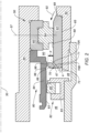
FIG. 2 is a cross-sectional view of the casing ofFIG. 1 illustrating a bearing assembly in a first axial position. -
FIG. 3 is a cross-sectional view of the casing and bearing assembly ofFIG. 2 in a second axial position. -
FIG. 1 illustrates agas turbine engine 20 configured as a turbofan engine. Thegas turbine engine 20 includes afan section 22, acompressor section 24, acombustor 26, and aturbine section 28 extending along anaxial centerline 30. The terms "forward" and "aft" are used herein to indicate position along theaxial centerline 30; referring to theengine 20 shown inFIG. 1 , thefan section 22 is disposed forward of thecompressor section 24, and thecompressor section 24 is disposed aft of thefan section 22. Thefan section 22 and a portion of the turbine section 28 (i.e., the low pressure turbine) are connected by alow pressure shaft 42. The term "radial" refers to a direction that is perpendicular to theaxial centerline 30 and may be used herein to indicate position relative to theaxial centerline 30; e.g., a first component positioned "radially inward" of a second component is disposed closer to theaxial centerline 30 than the second component, and conversely the second component is disposed "radially outward" of the first component. The term "axial" refers to a direction that is parallel to theaxial centerline 30. - The
compressor section 24 includes a plurality of compressor rotor stages 32, eachstage 32 having a plurality ofcompressor rotor blades 34 extending radially outward from a hub. The compressor rotor stages 32 and a portion of the turbine section 28 (i.e., the high pressure turbine) are connected by ahigh pressure shaft 44. The radially outermost surface of acompressor rotor blade 34 may be referred to as the rotor blade tip 36. Eachcompressor rotor stage 32 is configured for rotation about theaxial centerline 30. Thecompressor section 24 further includes one or more compressor stator vane stages 38. Each compressorstator vane stage 38 includes a plurality of stator vanes 40 (e.g., airfoils) spaced apart from one another around the circumference of the compressorstator vane stage 38. Each compressorstator vane stage 38 is non-rotational about theaxial centerline 30.Stator vanes 40 disposed immediately forward of acompressor rotor stage 32 are typically configured to guide airflow into thecompressor rotor stage 32 in a desirable orientation.Stator vanes 40 disposed immediately aft of acompressor rotor stage 32 are typically configured to guide airflow exiting thecompressor rotor stage 32 in a desirable orientation for downstream use. - Referring still to
FIG. 1 , thegas turbine engine 20 includes a plurality of bearingassemblies 50 configured to support thelow pressure shaft 42 and thehigh pressure shaft 44. Thelow pressure shaft 42 is supported at its forward end by a first bearing assembly 50A and a second bearing assembly 50B, and at an aft end thereof by a third bearing assembly 50C. The first bearing assembly 50A is disposed axially forward of the second bearing assembly 50B. Thehigh pressure shaft 42 is supported at its forward end by a fourth bearing assembly 50D and at an aft end thereof by a fifth bearing assembly 50E. As will be detailed herein, each bearing assembly 50A-E includes a bearing suitable for supporting theaforesaid shafts gas turbine engine 20 shown inFIG. 1 is provided as an example only and the present disclosure is not limited thereto. - Referring to
FIG. 2 , the bearingassembly 50 discussed in detail below is an example of a presentdisclosure bearing assembly 50 that may be used between astatic structure 52 and arotating shaft 54. Anengine centerline 30 is shown above the bearingassembly 50 to indicate the orientation of the bearingassembly 50 as shown inFIG. 2 . As will be detailed herein, the bearingassembly 50 includes a bearing 56 and aseal subassembly 80. - The bearing 56 includes an
inner race 60, anouter race 62, and a plurality of rollingelements 64 retained therebetween. Theouter race 62 includes an innerradial surface 68, an outerradial surface 65, a firstaxial end 67, a secondaxial end 69, and ashield member 66. Theshield member 66 extends radially inwardly from the innerradial surface 68 and is disposed at the firstaxial end 67 of theouter race 62. Theshield member 66 extends radially inwardly a distance X from the innerradial surface 68 of theouter race 62. InFIG. 2 , theshield member 66 is shown as integral with theouter race 62. Alternatively, theshield member 66 may be an independent component that is affixed to the annularouter race 62. Theouter race 62 further includes a plurality of drain holes 70. Eachdrain hole 70 extends between afirst end 70A disposed at the innerradial surface 68 and asecond end 70B disposed at the firstaxial end 67 of theouter race 62. The plurality of drain holes 70 may be disposed at respective positions spaced apart from one another around the circumference of theouter race 62. The plurality of drain holes 70 may be equidistantly spaced apart from one another around the circumference of theouter race 62, but the present disclosure is not limited to equidistant spacing. Eachdrain hole 70 may extend along anaxis 71 that is non-parallel to the engineaxial centerline 30. In the example diagrammatically shown inFIG. 2 , theaxis 71 of eachdrain hole 70 is disposed at an angle alpha ("a") that is skewed relative to theaxial centerline 30, such that thefirst end 70A of eachdrain hole 70 is disposed radially inward of (and axially separated from) thesecond end 70B of therespective drain hole 70. The angle alpha ("α") may be between 40 and 60 degrees. Theouter race 62 may have an undercut /chamfer 72 extending between the outerradial surface 65 of theouter race 62 and the firstaxial end 67 of theouter race 62. Theinner race 60 is affixed to a rotating shaft 54 (e.g., the low pressure shaft 42) and theouter race 62 is affixed to a static structure 52 (e.g., a static structure of the compressor section 24). In theexample bearing assembly 50 shown inFIG. 2 , the bearing 56 is positioned aft and downstream of theseal subassembly 80. - The
seal subassembly 80 includes aseal element 82 and aseal runner 84. Theseal element 82 is disposed radially outside of theseal runner 84. Theseal element 82 includes aseal element housing 83 and aseal ring 85. Theseal element 82 may be configured to allow theseal ring 85 to float within theseal element housing 83. Theseal element 82 may be a unitary annular structure or may comprise a plurality of elements that collectively form the respective annular structure; e.g., a plurality of circumferential segments. An example of anacceptable seal element 82 is one having acarbon seal ring 85, but the present disclosure is not limited thereto. - The
seal runner 84 may be a unitary annular structure or may comprise a plurality of elements that collectively form the respective annular structure; e.g., a plurality of circumferential segments. Theseal runner 84 may include aseal surface 93, acurved surface 96, and aradially extending protrusion 98. Theseal surface 93 extends axially and is configured for engagement with theseal ring 85. As will be described herein, thecurved surface 96 is configured to directionally alter a flow of air passing by thecurved surface 96, and theradially extending protrusion 98 may be configured to impede an airflow passing thereby. Thecurved surface 96 is disposed axially between theseal surface 93 and theprotrusion 98; i.e., theseal surface 93 axially terminates at thecurved surface 96. In the embodiment shown inFIG. 2 , a portion of thecurved surface 96 extends radially inward to form a recess into the body of the seal runner, and a portion of thecurved surface 96 extends radially outward to blend with theprotrusion 98. - In the bearing
assembly 50 diagrammatically shown inFIG. 2 , theseal element 82 is connected to thestatic structure 52 and theseal runner 84 is connected to therotating shaft 54. Theseal element 82 is configured to permit theseal ring 85 to engage with theseal surface 93 of theseal runner 84. The engagement between theseal ring 85 and theseal surface 93 is such that a flow of air may flow therebetween during operational segments of the gas turbine engine. Portions of theseal runner 84, the bearinginner race 60, the bearingouter race 62, and the rollingelements 64 define abearing cavity 90. Portions of thestatic structure 52, the bearingouter race 62, theseal element 82, and theseal runner 84 define alateral bearing cavity 48. - During operation of the
engine 20 and bearingassembly 50, alubricant flow 92 is directed at the aft side of the bearing 56. At least a portion of thelubricant flow 92 will migrate across the bearing 56 and will enter thebearing cavity 90. At the same time, a difference in static pressure will be present across theseal element 82; i.e., the static pressure ("P46") in the region denoted "46" (on the side of theseal element 82 axially opposite the lateral bearing cavity 48) will be greater than the static pressure ("P48") in thelateral bearing cavity 48 and the static pressure ("P90") within the bearingcavity 90; seeFIG. 3 . The difference in air pressure across theseal element 82 causes a flow of air ("leakage airflow") to pass between theseal ring 85 and theseal runner 84 during operational segments of thegas turbine engine 20. The characteristics (i.e., volumetric rate of flow, air velocity) of the leakage airflow will depend both on the magnitude of the pressure difference across theseal element 82 as well as the size of the gap between theseal ring 85 and theseal surface 93 of theseal runner 84. Thermal gradients within the engine during operational segments may cause the temperature ofrotating shaft 54 to differ from that of thestatic structure 52, and thermal expansion of the components may cause the gap between theseal element 82 and theseal surface 93 of theseal runner 84 to vary in magnitude. The gap between theseal ring 85 and theannular seal surface 93 may be circumferentially uniform, or it may vary at different circumferential locations. - The leakage airflow passing between the
seal ring 85 and the seal surface 93 (i.e., traveling in a direction from forward to aft) left unchecked may undesirably impinge on the bearing 56. The presentdisclosure bearing assembly 50 provides an improved configuration that mitigates or prevents leakage flow impingement on the bearing 56. For example, theshield member 66 portion of the bearingouter race 62 extending radially toward theseal runner 84 decreases the annular gap therebetween and is understood to block at least some of the leakage airflow. In addition, theradially extending protrusion 98 extends radially toward theshield member 66 of the bearingouter race 62 and decreases the annular gap therebetween. Theprotrusion 98 is also understood to block at least some of the leakage airflow traveling axially. Still further, thecurved surface 96 is understood to direct leakage airflow away from theseal runner 84 and towards theshield member 66 of the outer race 62 (diagrammatically shown as arrow 86). In this manner, at least a portion of the leakage airflow is directed away from the bearingcavity 90. That same portion of leakage airflow directed away from the bearingcavity 90 by thecurved surface 96 may also interfere with any leakage airflow traveling axially and thereby impede its axial progress. - The drain holes 70 provide an egress passage for lubrication that may collect within the bearing
cavity 90, allowing that lubricant to pass into thelateral bearing cavity 48 where it can be scavenged and returned into the lubrication system. - The bearing
assembly 50 is configured to not only accommodate component radial variances as described above but is also configured to accommodate relative axial travel between the rotating shaft 54 (and elements attached thereto) and the static structure 52 (and components attached thereto). During operation of theengine 20, the relative axial positions of the static portions and rotating portions of the bearingassembly 50 may vary.FIG. 2 illustrates the bearingassembly 50 in a first axial position configuration andFIG. 3 illustrates the bearingassembly 50 in a second axial position configuration.FIG. 3 diagrammatically illustrates the relative axial movement by the distance "AM". The differences in axial positions can be seen, for example by the relative axial positions of theseal runner 84 and theouter race 62. The bearing 56 has a bearingcenterline 57 that bisects theinner race 60 and the rollingelements 64. The bearingcenterline 57 does not change relative to theinner race 60 and the rollingelements 64, but may shift relative to theouter race 62, as can be diagrammatically seen inFIGS. 2 and3 . The bearing assembly components (e.g., theshield member 66, theseal runner protrusion 98, and the like are configured to permit the aforesaid axial travel between the rotating shaft 54 (and elements attached thereto) and the static structure 52 (and components attached thereto) without interference. - While the principles of the disclosure have been described above in connection with specific apparatuses and methods, it is to be clearly understood that this description is made only by way of example and not as limitation on the scope of the disclosure. Specific details are given in the above description to provide a thorough understanding of the embodiments. However, it is understood that the embodiments may be practiced without these specific details.
- It is noted that the embodiments may be described as a process which is depicted as a flowchart, a flow diagram, a block diagram, etc. Although any one of these structures may describe the operations as a sequential process, many of the operations can be performed in parallel or concurrently. In addition, the order of the operations may be rearranged. A process may correspond to a method, a function, a procedure, a subroutine, a subprogram, etc.
- The singular forms "a," "an," and "the" refer to one or more than one, unless the context clearly dictates otherwise. For example, the term "comprising a specimen" includes single or plural specimens and is considered equivalent to the phrase "comprising at least one specimen." The term "or" refers to a single element of stated alternative elements or a combination of two or more elements unless the context clearly indicates otherwise. As used herein, "comprises" means "includes." Thus, "comprising A or B," means "including A or B, or A and B," without excluding additional elements.
- It is noted that various connections are set forth between elements in the present description and drawings (the contents of which are included in this disclosure by way of reference). It is noted that these connections are general and, unless specified otherwise, may be direct or indirect and that this specification is not intended to be limiting in this respect. Any reference to attached, fixed, connected or the like may include permanent, removable, temporary, partial, full and/or any other possible attachment option.
- No element, component, or method step in the present disclosure is intended to be dedicated to the public regardless of whether the element, component, or method step is explicitly recited in the claims. No claim element herein is to be construed under the provisions of 35 U.S.C. 112(f) unless the element is expressly recited using the phrase "means for." As used herein, the terms "comprise", "comprising", or any other variation thereof, are intended to cover a non-exclusive inclusion, such that a process, method, article, or apparatus that comprises a list of elements does not include only those elements but may include other elements not expressly listed or inherent to such process, method, article, or apparatus.
- While various inventive aspects, concepts and features of the disclosures may be described and illustrated herein as embodied in combination in the exemplary embodiments, these various aspects, concepts, and features may be used in many alternative embodiments, either individually or in various combinations and sub-combinations thereof. Unless expressly excluded herein all such combinations and sub-combinations are intended to be within the scope of the present application. Still further, while various alternative embodiments as to the various aspects, concepts, and features of the disclosures--such as alternative materials, structures, configurations, methods, devices, and components, and so on--may be described herein, such descriptions are not intended to be a complete or exhaustive list of available alternative embodiments, whether presently known or later developed. Those skilled in the art may readily adopt one or more of the inventive aspects, concepts, or features into additional embodiments and uses within the scope of the present application even if such embodiments are not expressly disclosed herein. For example, in the exemplary embodiments described above within the Detailed Description portion of the present specification, elements may be described as individual units and shown as independent of one another to facilitate the description. In alternative embodiments, such elements may be configured as combined elements. It is further noted that various method or process steps for embodiments of the present disclosure are described herein. The description may present method and/or process steps as a particular sequence. However, to the extent that the method or process does not rely on the particular order of steps set forth herein, the method or process should not be limited to the particular sequence of steps described. As one of ordinary skill in the art would appreciate, other sequences of steps may be possible. Therefore, the particular order of the steps set forth in the description should not be construed as a limitation.
Claims (15)
- A gas turbine engine (20), comprising:a static structure (52);a rotating shaft (54) disposed radially inward of the static structure (52); anda bearing assembly (50) that includes:a bearing (56) having an inner race (60), an outer race (62), and a plurality of roller elements (64) disposed between the inner race (60) and the outer race (62), wherein the inner race (60) is coupled with the rotating shaft (54) and the outer race (62) is coupled with the static structure (52), and the outer race (62) includes a shield member (66) that extends radially inward toward the rotating shaft (54); anda seal subassembly (80) that includes a seal element (82) coupled with the static structure (52), and a seal runner (84) coupled with the rotating shaft (54), wherein the seal element (82) is disposed to engage with the seal runner (84);wherein a portion of the seal runner (84), a portion of the outer race (62) including the shield member (66), and a portion of the inner race (60) define a first bearing cavity (90); andwherein a portion of the seal runner (84), a portion of the outer race (62) including the shield member (66), a portion of the seal element (82), and a portion of the static structure (52) define a lateral bearing cavity (48), and wherein the lateral bearing cavity (48) is disposed axially between the first bearing cavity (90) and the seal element (82); andwherein the outer race (62) includes a plurality of drain holes (70) that provide fluid communication between the first bearing cavity (90) and the lateral bearing cavity (48).
- The gas turbine engine (20) of claim 1, wherein the outer race (62) has an inner radial surface (68), an outer radial surface (65), a first axial end (67), and a second axial end (69); and
wherein the shield member (66) extends radially inwardly from the inner radial surface (68) and the shield member (66) is disposed at the first axial end (67) of the outer race (62). - The gas turbine engine (20) of claim 2, wherein the shield member (66) is integral with the outer race (62).
- The gas turbine engine (20) of claim 1, 2 or 3, wherein each said drain hole of the plurality of drain holes (70) extends along an axis (71) disposed at an angle (α) skewed relative to an axial centerline (30) of the engine (20).
- The gas turbine engine (20) of any preceding claim, wherein each drain hole (70) has a first end (70A) in communication with the first bearing cavity (90) and a second end (70B) in communication with the lateral bearing cavity (48), and the first end (70A) is disposed radially inward of and axially spaced apart from the second end (70B).
- The gas turbine engine (20) of claim 5, wherein the first end (70A) of each drain hole (70) is disposed at an intersection between the inner radial surface (68) of the outer race (62) and the shield member (66).
- The gas turbine engine (20) of any preceding claim, wherein the seal runner (84) has a curved surface (96) disposed axially between a seal surface (93) and a protrusion (98) that extends outwardly relative to the seal surface (93).
- The gas turbine engine (20) of claim 7, wherein a portion of the curved surface (96) forms a recess into the seal runner (84) and a portion of the curved surface (96) extends radially outward to blend with the protrusion (98).
- A gas turbine engine (20), comprising:a static structure (52);a rotating shaft (54) disposed radially inward of the static structure (52); anda bearing assembly (50) that includes:a bearing (56) having an inner race (60), an outer race (62), and a plurality of roller elements (64) disposed between the inner race (60) and the outer race (62), wherein the inner race (60) is coupled with the rotating shaft (54) and the outer race (62) is coupled with the static structure (52), and the outer race (62) includes an inner radial surface (68), an outer radial surface (65), and a shield member (66) that extends radially away from the inner radial surface (68) in a direction toward the rotating shaft (54); anda seal subassembly (80) that includes a seal element (82) coupled with the static structure (52), and a seal runner (84) coupled with the rotating shaft (54), the seal runner (84) having a seal surface (93) and a protrusion (98) that extends outwardly relative to the seal surface (93); wherein the seal element (82) is disposed to engage with the seal surface (93) of the seal runner (84);wherein rotating shaft (54) and the static structure (52) are configured to permit relative axial travel therebetween between a first axial position wherein the seal runner protrusion (98) and the shield member (66) are aligned with one another, and a second axial position wherein the seal runner protrusion (98) and the shield member (66) are misaligned with one another.
- The gas turbine engine (20) of claim 9, wherein a portion of the seal runner (84), a portion of the outer race (62) including the shield member (66), and a portion of the inner race (60) define a first bearing cavity (90); andwherein a portion of the seal runner (84), a portion of the outer race (62) including the shield member (66), a portion of the seal element (82), and a portion of the static structure (52) define a lateral bearing cavity (48), and wherein the lateral bearing cavity (48) is disposed axially between the first bearing cavity (90) and the seal element (82); andwherein the outer race (62) includes a plurality of drain holes (70) that provide fluid communication between the first bearing cavity (90) and the lateral bearing cavity (48).
- The gas turbine engine (20) of claim 10, wherein each said drain hole of the plurality of drain holes (70) extends along an axis (71) disposed at an angle (α) skewed relative to an axial centerline (30) of the engine (20),
wherein, optionally, a first end (70A) of each drain hole (70) is disposed at an intersection between the inner radial surface (68) of the outer race (62) and the shield member (66). - The gas turbine engine (20) of claim 9, 10 or 11, wherein the seal runner (84) has a curved surface (96) disposed axially between the seal surface (93) and the seal runner protrusion (98),
wherein, optionally, a portion of the curved surface (96) forms a recess into the seal runner (84) and a portion of the curved surface (96) extends radially outward to blend with the protrusion (98). - The gas turbine engine (20) of any preceding claim, wherein the seal element (82) includes a seal element housing (83) and a seal ring (85); and
wherein, optionally, in the first axial position, the seal ring (85) engages with a first segment of the seal runner seal surface (93), and in the second axial position the seal ring (85) engages with a second segment of the seal runner seal surface (93). - A bearing assembly (50) for use between a static structure (52) and a rotating shaft (54) of a gas turbine engine (20), wherein the rotating shaft (54) is disposed radially inward of the static structure (52), the bearing assembly (50) comprising:a bearing (56) having an inner race (60), an outer race (62), and a plurality of roller elements (64) disposed between the inner race (60) and the outer race (62), wherein the inner race (60) is configured for coupling with the rotating shaft (54) and the outer race (62) is configured for coupling with the static structure (52), and the outer race (62) has an inner radial surface (68), an outer radial surface (65), a shield member (66) that extends radially away from the inner radial surface (68), and a plurality of drain holes (70); anda seal subassembly (80) that includes a seal element (82) configured for coupling with the static structure (52), and a seal runner (84) configured for coupling with the rotating shaft (54);wherein in an assembled form, the seal subassembly (80) is configured such that the seal element (82) is disposed to engage with the seal runner (84); andwherein the bearing assembly (50) is configured to have an assembled form relative to the static structure (52) and the rotating shaft (54), and in the assembled form a portion of the seal runner (84), a portion of the outer race (62) including the shield member (66), and a portion of the inner race (60) define a first bearing cavity (90), and in the assembled form a portion of the seal runner (84), a portion of the outer race (62) including the shield member (66), a portion of the seal element (82), and a portion of the static structure (52) define a lateral bearing cavity (48), the lateral bearing cavity (48) disposed axially between the first bearing cavity (90) and the seal element (82), and in the assembled form the plurality of drain holes (70) provide fluid communication between the first bearing cavity (90) and the lateral bearing cavity (48),wherein, optionally, the seal element (82) includes a seal element housing (83) and a seal ring (85).
- The bearing assembly (50) of claim 14, wherein the seal runner (84) has a seal surface (93) and a protrusion (98) that extends outwardly relative to the seal surface (93), and the seal element (82) is disposed to engage with the seal surface (93) of the seal runner (84).
wherein, optionally, the seal runner (84) further includes a curved surface (96) disposed axially between the seal surface (93) and the protrusion (98), and a portion of the curved surface (96) forms a recess into the seal runner (84) and a portion of the curved surface (96) extends radially outward to blend with the protrusion (98).
Applications Claiming Priority (1)
| Application Number | Priority Date | Filing Date | Title |
|---|---|---|---|
| US18/377,397 US12398674B2 (en) | 2023-10-06 | 2023-10-06 | Bearing assembly for a gas turbine engine |
Publications (2)
| Publication Number | Publication Date |
|---|---|
| EP4534808A2 true EP4534808A2 (en) | 2025-04-09 |
| EP4534808A3 EP4534808A3 (en) | 2025-06-11 |
Family
ID=93014919
Family Applications (1)
| Application Number | Title | Priority Date | Filing Date |
|---|---|---|---|
| EP24205048.2A Pending EP4534808A3 (en) | 2023-10-06 | 2024-10-07 | Bearing assembly for a gas turbine engine |
Country Status (3)
| Country | Link |
|---|---|
| US (1) | US12398674B2 (en) |
| EP (1) | EP4534808A3 (en) |
| CA (1) | CA3255437A1 (en) |
Family Cites Families (20)
| Publication number | Priority date | Publication date | Assignee | Title |
|---|---|---|---|---|
| US2992842A (en) * | 1958-04-21 | 1961-07-18 | United Aircraft Corp | Oil scrubbed face seal |
| US2990202A (en) * | 1958-09-18 | 1961-06-27 | United Aircraft Corp | Labyrinth face seal plate |
| GB988500A (en) | 1964-02-21 | 1965-04-07 | Rolls Royce | Bearing |
| GB2043799B (en) | 1979-03-05 | 1983-03-16 | Rolls Royce | Draining oil from bearing |
| US4406460A (en) * | 1982-11-01 | 1983-09-27 | United Technologies Corporation | Anti-weepage valve for rotating seals |
| US4542623A (en) | 1983-12-23 | 1985-09-24 | United Technologies Corporation | Air cooler for providing buffer air to a bearing compartment |
| US4928978A (en) * | 1988-04-07 | 1990-05-29 | United Technologies Corporation | Rotating shaft seal |
| US6579010B2 (en) * | 2001-08-31 | 2003-06-17 | General Electric Company | Retainer nut |
| US20080135336A1 (en) * | 2006-12-11 | 2008-06-12 | Jewess Gordon F | Under race bearing lubrication system for gas turbine engines |
| US7806596B2 (en) * | 2007-08-31 | 2010-10-05 | Hamilton Sundstrand Corporation | High speed bearing system with bind-free axial displacement |
| GB201101226D0 (en) | 2011-01-25 | 2011-03-09 | Rolls Royce Plc | A bearing race for a rolling-element bearing |
| WO2014152300A1 (en) | 2013-03-15 | 2014-09-25 | United Technologies Corporation | Shield for arranging between a bearing and a rotating seal element |
| WO2015094463A1 (en) * | 2013-12-20 | 2015-06-25 | United Technologies Corporation | Seal runner |
| US9777592B2 (en) | 2013-12-23 | 2017-10-03 | Pratt & Whitney Canada Corp. | Post FBO windmilling bumper |
| US9752616B2 (en) * | 2015-03-27 | 2017-09-05 | Pratt & Withney Canada Corp. | Bearing system with bearing damper |
| US10753219B2 (en) * | 2015-05-26 | 2020-08-25 | Pratt & Whitney Canada Corp. | Internally cooled seal runner and method of cooling seal runner of a gas turbine engine |
| FR3062679B1 (en) * | 2017-02-07 | 2019-04-19 | Safran Aircraft Engines | VIROLE FOR REDUCING THE PRESSURE REDUCTION IN THE NEIGHBORHOOD OF THE UPPER JOINT OF A TURBOJET ENGINE BEARING ENCLOSURE |
| CN107060898B (en) | 2017-06-15 | 2019-03-08 | 中国科学院工程热物理研究所 | Floating ring seal assembly with accumulation groove |
| US11085330B2 (en) * | 2018-02-19 | 2021-08-10 | Pratt & Whitney Canada Corp. | Seal and bearing assembly with bearing outer portion defining seal static portion |
| US10968774B2 (en) * | 2018-10-11 | 2021-04-06 | Pratt & Whitney Canada Corp. | Bearing housing with baffles |
-
2023
- 2023-10-06 US US18/377,397 patent/US12398674B2/en active Active
-
2024
- 2024-10-03 CA CA3255437A patent/CA3255437A1/en active Pending
- 2024-10-07 EP EP24205048.2A patent/EP4534808A3/en active Pending
Also Published As
| Publication number | Publication date |
|---|---|
| US12398674B2 (en) | 2025-08-26 |
| US20250116231A1 (en) | 2025-04-10 |
| EP4534808A3 (en) | 2025-06-11 |
| CA3255437A1 (en) | 2025-05-23 |
Similar Documents
| Publication | Publication Date | Title |
|---|---|---|
| US11073045B2 (en) | Turbine shroud assembly with case captured seal segment carrier | |
| US5622475A (en) | Double rabbet rotor blade retention assembly | |
| EP3705703B1 (en) | Shield for arranging between a bearing and a rotating seal element | |
| EP3252280B1 (en) | Circumferential plenum for oil damper | |
| US10781709B2 (en) | Turbine engine with a seal | |
| US5791871A (en) | Turbine engine rotor assembly blade outer air seal | |
| EP2776682B1 (en) | Turbomachinery seal | |
| US10184345B2 (en) | Cover plate assembly for a gas turbine engine | |
| CA2406479C (en) | Weep plug | |
| US12590634B2 (en) | Piston seal ring bypass | |
| US12123305B2 (en) | Split piston ring seal for a rotating assembly and method of sealing | |
| US20190226585A1 (en) | Hydrodynamic Intershaft Piston Ring Seal | |
| EP3608506A1 (en) | Gas turbine vane comprising a trunion with cooling channels | |
| US12116897B2 (en) | Turbine stator assembly with a radial degree of freedom between a guide vane assembly and a sealing ring | |
| US12398674B2 (en) | Bearing assembly for a gas turbine engine | |
| US12601274B1 (en) | Oil shield for a rotating assembly | |
| EP3626933B1 (en) | High pressure turbine rear side plate | |
| US20200032669A1 (en) | Shrouded blade assemblies | |
| US12480419B1 (en) | Outer air seal (OAS) assembly for a gas turbine engine | |
| US20250382893A1 (en) | Shrouded turbine assembly for gas turbine engine | |
| US12326089B2 (en) | Seal assembly for a gas turbine engine | |
| US12366172B1 (en) | Seal assembly for a rotary machine having a flexible joint | |
| US20240229671A9 (en) | Turbomachine distributor comprising a gas reintroduction duct with a tangential component | |
| CN119353060A (en) | Seal assembly having at least one damping element |
Legal Events
| Date | Code | Title | Description |
|---|---|---|---|
| PUAI | Public reference made under article 153(3) epc to a published international application that has entered the european phase |
Free format text: ORIGINAL CODE: 0009012 |
|
| STAA | Information on the status of an ep patent application or granted ep patent |
Free format text: STATUS: THE APPLICATION HAS BEEN PUBLISHED |
|
| AK | Designated contracting states |
Kind code of ref document: A2 Designated state(s): AL AT BE BG CH CY CZ DE DK EE ES FI FR GB GR HR HU IE IS IT LI LT LU LV MC ME MK MT NL NO PL PT RO RS SE SI SK SM TR |
|
| PUAL | Search report despatched |
Free format text: ORIGINAL CODE: 0009013 |
|
| AK | Designated contracting states |
Kind code of ref document: A3 Designated state(s): AL AT BE BG CH CY CZ DE DK EE ES FI FR GB GR HR HU IE IS IT LI LT LU LV MC ME MK MT NL NO PL PT RO RS SE SI SK SM TR |
|
| RIC1 | Information provided on ipc code assigned before grant |
Ipc: F01D 11/00 20060101ALI20250507BHEP Ipc: F01D 25/16 20060101ALI20250507BHEP Ipc: F01D 25/18 20060101AFI20250507BHEP |
|
| STAA | Information on the status of an ep patent application or granted ep patent |
Free format text: STATUS: REQUEST FOR EXAMINATION WAS MADE |
|
| 17P | Request for examination filed |
Effective date: 20251211 |