EP4534795A2 - Verfahren zur bestimmung eines parameters eines flusses einer erzeugten flüssigkeit in einem bohrloch - Google Patents
Verfahren zur bestimmung eines parameters eines flusses einer erzeugten flüssigkeit in einem bohrloch Download PDFInfo
- Publication number
- EP4534795A2 EP4534795A2 EP25159865.2A EP25159865A EP4534795A2 EP 4534795 A2 EP4534795 A2 EP 4534795A2 EP 25159865 A EP25159865 A EP 25159865A EP 4534795 A2 EP4534795 A2 EP 4534795A2
- Authority
- EP
- European Patent Office
- Prior art keywords
- flow
- fluid
- injection
- tracer substance
- location
- Prior art date
- Legal status (The legal status is an assumption and is not a legal conclusion. Google has not performed a legal analysis and makes no representation as to the accuracy of the status listed.)
- Pending
Links
Images

Classifications
-
- E—FIXED CONSTRUCTIONS
- E21—EARTH OR ROCK DRILLING; MINING
- E21B—EARTH OR ROCK DRILLING; OBTAINING OIL, GAS, WATER, SOLUBLE OR MELTABLE MATERIALS OR A SLURRY OF MINERALS FROM WELLS
- E21B43/00—Methods or apparatus for obtaining oil, gas, water, soluble or meltable materials or a slurry of minerals from wells
- E21B43/12—Methods or apparatus for controlling the flow of the obtained fluid to or in wells
- E21B43/121—Lifting well fluids
- E21B43/122—Gas lift
-
- E—FIXED CONSTRUCTIONS
- E21—EARTH OR ROCK DRILLING; MINING
- E21B—EARTH OR ROCK DRILLING; OBTAINING OIL, GAS, WATER, SOLUBLE OR MELTABLE MATERIALS OR A SLURRY OF MINERALS FROM WELLS
- E21B43/00—Methods or apparatus for obtaining oil, gas, water, soluble or meltable materials or a slurry of minerals from wells
- E21B43/12—Methods or apparatus for controlling the flow of the obtained fluid to or in wells
- E21B43/121—Lifting well fluids
- E21B43/122—Gas lift
- E21B43/123—Gas lift valves
-
- E—FIXED CONSTRUCTIONS
- E21—EARTH OR ROCK DRILLING; MINING
- E21B—EARTH OR ROCK DRILLING; OBTAINING OIL, GAS, WATER, SOLUBLE OR MELTABLE MATERIALS OR A SLURRY OF MINERALS FROM WELLS
- E21B47/00—Survey of boreholes or wells
- E21B47/10—Locating fluid leaks, intrusions or movements
- E21B47/11—Locating fluid leaks, intrusions or movements using tracers; using radioactivity
-
- G—PHYSICS
- G01—MEASURING; TESTING
- G01F—MEASURING VOLUME, VOLUME FLOW, MASS FLOW OR LIQUID LEVEL; METERING BY VOLUME
- G01F25/00—Testing or calibration of apparatus for measuring volume, volume flow or liquid level or for metering by volume
- G01F25/10—Testing or calibration of apparatus for measuring volume, volume flow or liquid level or for metering by volume of flowmeters
- G01F25/12—Testing or calibration of apparatus for measuring volume, volume flow or liquid level or for metering by volume of flowmeters using tracer
-
- G—PHYSICS
- G01—MEASURING; TESTING
- G01F—MEASURING VOLUME, VOLUME FLOW, MASS FLOW OR LIQUID LEVEL; METERING BY VOLUME
- G01F1/00—Measuring the volume flow or mass flow of fluid or fluent solid material wherein the fluid passes through a meter in a continuous flow
- G01F1/704—Measuring the volume flow or mass flow of fluid or fluent solid material wherein the fluid passes through a meter in a continuous flow using marked regions or existing inhomogeneities within the fluid stream, e.g. statistically occurring variations in a fluid parameter
-
- G—PHYSICS
- G01—MEASURING; TESTING
- G01N—INVESTIGATING OR ANALYSING MATERIALS BY DETERMINING THEIR CHEMICAL OR PHYSICAL PROPERTIES
- G01N21/00—Investigating or analysing materials by the use of optical means, i.e. using sub-millimetre waves, infrared, visible or ultraviolet light
- G01N21/17—Systems in which incident light is modified in accordance with the properties of the material investigated
- G01N2021/1746—Method using tracers
Definitions
- the present invention relates to the field of quantifying production rates from wells, and in particular, it relates to a method for determining a parameter of a flow of a produced fluid in a well.
- the invention further relates to a method for improving a flow rate of produced fluid in a well, a method for determining a flow rate of injection of a gas-lift gas into a well, and an apparatus for determining a parameter of a flow of a produced fluid in a well.
- a parameter of a flow of a produced fluid in a well e.g. to quantify a production rate from the well.
- it can be important to quantify a flow rate in a well to investigate if the well is producing as expected, and to investigate effects of how changing a setting of a control unit may affect the production rate.
- flow meters that may be used to obtain a measurement of a flow rate of a fluid from a well.
- the flow meters are expensive, and the accuracy of the flow meters can often be poor.
- the flow meters may also require frequent replacement and/or maintenance to provide acceptable accuracy. Because of the disadvantages, many wells do not have a flow meter to quantify production rate.
- the production line of the well can be connected to a test separator.
- This can be challenging: Some wells do not have test separators easily accessible. For some installations, it is necessary to acquire the services of a truck or a ship having a test separator and to connect said test separator to the well to be tested. Even when test separators are available on an installation site, and the test separator can easily be connected to the production line of a well, it may be inefficient to use the test separator. For example, if an operator wants to test the effect of a change of rate of injection of gas-lift gas into a well, it may take several days for the resulting rate of production to stabilize and to be obtainable from measurements by use of the test separator. In such cases, the production line of said well may occupy the test separator for a long time. This may be very problematic as test separator capacity can often be a limited resource. Furthermore, production from a well may be lost when the well is connected to the test separator.
- An object of the invention is to remedy or to reduce at least one of the drawbacks of prior art.
- a method for determining a parameter of a flow of a produced fluid in a well comprising a production flow line and an injection line, the production flow line comprising a production bore of the well, the injection line being connected to the production flow line at a first location, and the well having a second location in the production flow line downstream of the first location, the method comprising the steps of:
- the parameter of a flow to be determined may be a parameter to quantify the flow, e.g. to quantify a rate of production.
- the method advantageously may not require production to be routed to a test separator to determine the parameter of the flow.
- the parameter may be a flow rate of the flow of produced fluid.
- the means for obtaining said measurements may be means adapted to be connected to the production line with no need for diverting or stopping production.
- a huge number of substances may be used as a tracer substance, including carbon dioxide, nitrogen, helium, argon, a radioactive material, or another substance.
- first location in the production line downstream of the first location means a point in the production line away from the first location in the direction of the fluid flow in the production line.
- the fluid flow of produced fluid in the production line typically goes from an underground fluid reservoir towards a separator.
- first location may typically be closer to the reservoir than the second location, and the second location may typically be closer to the separator than the first location.
- the first location may be a downhole location.
- the second location may be a topside location.
- Downhole refers to a position in a wellbore below the surface of a ground, whereas “topside” refers to a position above the surface.
- a spectrometer or a chromatograph may be used as the means for obtaining said measurements.
- Other devices may be used as the means for obtaining said measurements.
- the means may be connected to the production line to determine which substances are present in the flow, and/or a concentration of present substances. It may primarily be of interest, for the execution of the method, to quantify and/or to find a concentration of the tracer substance in particular.
- the measurement may be obtained continuously. Obtaining a continuous measurement may provide more and/or better information.
- a continuous measurement may e.g. provide a continuous flow pattern of the produced fluid over the duration of the continuous measurement.
- a method of improving a flow rate of produced fluid in a well comprising a production flow line and an injection line, the production flow line comprising a production bore of the well, the injection line being connected to the production flow line at a first location and the well having a second location in the production flow line downstream of the first location, the well comprising a control unit that may be adjusted to affect the flow rate of produced fluid from the well, wherein the control unit is a valve for adjusting a rate of injection of gas-lift gas, the method comprising the steps of:
- the step of comparing the first parameter to the second parameter to determine an effect of changing the setting of the control unit may comprise the step of determining which of the first setting and the second setting that results in a best flow rate of produced fluid in the well.
- the method may comprise the step of choosing the setting resulting in the best production rate as a setting for the well, to improve the flow rate of produced fluid in the well.
- a well typically has one or more valves or other control units that may be adjusted wherein said adjustment may affect a rate of production of produced fluid from the well.
- a control unit to adjust a rate of injection of gas-lift gas for a gas-lift well, and a control unit in the production line.
- Said control unit may typically be a control valve, a butterfly valve or a choke valve.
- the measurement of the tracer substance in the produced fluid may be a measurement of the tracer substance in a produced gas.
- Wells may typically produce a mixture of gas and liquid, and it may be possible and advantageous for the measurement to be a measurement of a gas portion of the total produced fluid and to thereafter correlate the resulting determined parameter of and/or effect on the produced gas to a corresponding parameter of and/or effect on the produced liquid.
- the produced liquid may typically comprise oil.
- the correlation may be made as a gas/oil ratio (GOR) and a gas/liquid ratio (GLR) in the produced fluid may be known and substantially constant over a period of time. An increase or decrease to e.g. a production rate of a gas may therefore easily be used to determine a corresponding increase or decrease to a production rate of a liquid.
- the step of obtaining a measurement of the tracer substance may include determining a concentration of the tracer in a flow of fluid at the second location.
- the step of using the measurement of the tracer substance to determine the parameter of the flow may include dividing the known rate of injection by the determined concentration of the tracer substance in the flow at the second location.
- the produced fluid at the second location may typically comprise a reservoir fluid from a fluid reservoir.
- the reservoir fluid may comprise a plurality of substances.
- Q O Q f 2 GOR .
- the method may thus be used to determine a parameter of flow of liquid and/or oil, in addition to the parameter of the parameter of flow of gas.
- the method may be used to determine a flow rate of all phases of a multiphase flow.
- the substance used as a tracer substance may be present in the reservoir fluid as one of the plurality of substances.
- the reservoir liquid may be saturated with said tracer substance.
- the injected tracer substance may not become absorbed by a liquid of the reservoir fluid. Instead, the injected tracer may follow the fluid flow fully as a component of the gas of the produced fluid.
- the step of determining a concentration of the tracer substance may comprise:
- the step of using the measurement of the tracer substance to determine the parameter of the flow of the produced fluid may comprise using the first concentration of tracer substance and the second concentration of tracer substance.
- the tracer substance may be injected in a flow of fluid including a gas-lift gas. This may typically be the case if the method is to be applied to a gas-lift well.
- the well may be a gas-lift well.
- the injection line may be a chemical injection line or a gas lift injection line.
- the parameter of the flow may be related to a quantification of the flow.
- a plurality of different settings of the control unit may be used. At least one measurement of the tracer substance at the second location may be obtained for each of the different settings by use of the means for obtaining the measurement. The plurality of measurements may be used to determine a best setting for improving the flow rate of the produced fluid from the well.
- the method according to the first aspect of the invention may be applied to a plurality of wells sharing a source of gas-lift gas, to determine a best distribution of gas-lift gas to the wells for improving the flow rate of produced fluid from each well to obtain a best total production of fluid from the plurality of wells.
- the source of gas-lift gas may not have the capacity to sufficiently provide each well with the optimal amount of gas-lift gas for the well. It may then be advantageous to apply the method according to the invention to a number or all of the gas-lift wells to determine a best distribution of gas-lift gas to achieve a best rate of total production from the wells.
- the control unit may be a choke valve.
- the control unit which may be a choke valve, may be placed in the production line, downstream of the first location.
- the described method, and/or the method according to the first aspect of the invention may comprise the step of determining a rate of injection of the tracer substance.
- the step of determining the rate of injection of the tracer substance may comprise using a device for measuring an amount of flow of fluid and/or using a device for determining a concentration of a substance in a flow of fluid.
- the device for measuring an amount of flow of fluid may be a flow meter.
- the device for determining a concentration of a substance in a flow of fluid may be a chromatograph or a spectrometer.
- the described method, and/or the invention according to the first aspect of the invention may comprise the step of determining a rate of injection of injected gas-lift gas.
- the step of determining the rate of injection of injected gas-lift gas comprises using a device for measuring an amount of flow of fluid and/or using a device for determining a concentration of a substance in a flow of fluid.
- Some wells may have gas-injection lines comprising a flow meter that may give an accurate reading of said rate.
- Other wells may have a flow meter where the accuracy is not sufficient or not known or may not have a flow meter at all. It may then be necessary to connect a flow meter to said injection line, or to determine the rate of injection by use of other means.
- the method may further comprise a step of determining a production rate of a fluid from a reservoir by subtracting a gas-lift gas injection rate from a determined production flow rate.
- the production rate of the fluid from the reservoir may be a production rate of a gas from the reservoir, and the determined production flow rate may be the production flow rate of a gas.
- the gas may be a gas in a multiphase flow.
- the device for determining a concentration of a substance in a flow of fluid may be a spectrometer or a chromatograph.
- the step of determining the rate of injection may then comprise adding a known quantity of tracer substance and/or injecting a tracer substance at a known rate of injection into the injection line in a first position in the injection line, and then to use the device for determining a concentration of a substance in a flow of fluid to determine the concentration of the tracer substance at a second position in the injection line, where the second position is downstream of the first position.
- a method for determining a rate of injection of a gas-lift gas into a well comprising a production flow line and an injection line, the injection line being connected to the production flow line, the method comprising the following steps:
- the method according to the second aspect of the invention may comprise steps described above.
- an apparatus for performing the method according to the first aspect of the invention and for determining a parameter of a flow of a produced fluid from a well comprising:
- the apparatus may alternatively to being an apparatus for performing the method according to the first aspect of the invention, or additionally to being an apparatus for performing the method according to the first aspect of the invention, be an apparatus for performing the method according to the second aspect of the invention.
- the apparatus may further comprise a container for containing the tracer substance.
- the container may be connected to the injection line for supplying the tracer substance into the injection line.
- the apparatus may comprise a device for measuring an amount of flow of fluid and/or a device for determining a concentration of a substance in a flow of fluid, wherein the device or the devices may be arranged for determining a rate of fluid flowing through the injection line.
- the apparatus may further have a control unit to adjust an injection rate of an injected fluid and/or substance.
- the control unit may be arranged to the injection line.
- the apparatus may further have a control unit to adjust a production flow rate arranged to the production flow line.
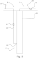
- Figure 1 shows an apparatus 1 for determining a parameter of a flow of a produced fluid from a well 3.
- the well has a production flow line 2 comprising a production bore 25 and an injection line 23 connected to the production flow line 2 in a first location 21 of the production flow line 2.
- a spectrometer 11 for obtaining a measurement of a tracer substance is arranged to obtain a measurement of the tracer substance in a flow of fluid.
- the flow of fluid is a mixture of a reservoir fluid from a reservoir (not shown) and a fluid injected from the injection line into the production flow line in the first location 21.
- the direction of flow is from the reservoir, through the first location 21, towards and through the second location 22.
- the second location 22 can be said to be downstream of the first location 21.
- a method for determining a parameter of a flow of a produced fluid in the well 3, using the apparatus 1, is performed as follows: A tracer substance is injected into the production flow line 2 at the first location 21, the tracer substance being injected at a known rate of injection. The spectrometer 11 obtains a measurement of the tracer substance at the second location 22. More precisely, the spectrometer 11 obtains a measurement of a concentration of the tracer substance in the flow of fluid in the second location 22 of the production flow line 2. Then, the measurement of concentration of tracer substance is used to determine the parameter of the flow of the produced fluid. More precisely, the flow rate of produced fluid is determined.
- the produced fluid measurement of concentration of tracer substance in this embodiment is a concentration of tracer substance of a flow of gas in the flow of fluid.
- Q f 2 is a flow rate of the gas.
- the flow rate of oil may thereafter be determined as above.
- tracer substance is added to the fluid stream in the injection line at a known rate.
- the spectrometer 12 is used to determine a concentration of the tracer substance in the second position in the injection line.
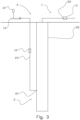
- Figure 3 shows an embodiment having a control unit 14 in the form of a choke valve 14 in the injection line 23 to adjust an injection rate of a gas-lift gas.
- the injection line 23 further has a spectrometer 12 for determining a concentration of an injected tracer substance placed downstream of a device 13 for supplying tracer substance into the injection line 23.
- the embodiment in Figure 3 has a spectrometer 11 in a second location 22 in the production flow line 2 downstream of a first location 21, where the injection line 23 connects to the production flow line 2.
- the first location 21 is downhole, whereas the second location is topside.
- the embodiment shown in Figure 3 is highly advantageous compared to prior art, as to find a resulting flow rate from a change of injection rate with no need for connecting the production flow line to a separator.
Landscapes
- Mining & Mineral Resources (AREA)
- Life Sciences & Earth Sciences (AREA)
- Engineering & Computer Science (AREA)
- Geology (AREA)
- Physics & Mathematics (AREA)
- Fluid Mechanics (AREA)
- Environmental & Geological Engineering (AREA)
- General Life Sciences & Earth Sciences (AREA)
- Geochemistry & Mineralogy (AREA)
- Geophysics (AREA)
- General Physics & Mathematics (AREA)
- Measuring Volume Flow (AREA)
- Details Of Flowmeters (AREA)
Applications Claiming Priority (4)
| Application Number | Priority Date | Filing Date | Title |
|---|---|---|---|
| NO20180785A NO345172B1 (en) | 2018-06-07 | 2018-06-07 | A method for determining a parameter of a flow of a produced fluid in a well |
| PCT/NO2019/000015 WO2019235936A1 (en) | 2018-06-07 | 2019-06-05 | A method for determining a parameter of a flow of a produced fluid in a well |
| EP19814481.8A EP3803047B1 (de) | 2018-06-07 | 2019-06-05 | Verfahren zur bestimmung eines parameters einer strömung eines erzeugten fluids in einem bohrloch |
| EP23188477.6A EP4242420B1 (de) | 2018-06-07 | 2019-06-05 | Verfahren zur bestimmung eines parameters eines flusses einer erzeugten flüssigkeit in einem bohrloch |
Related Parent Applications (3)
| Application Number | Title | Priority Date | Filing Date |
|---|---|---|---|
| EP19814481.8A Division EP3803047B1 (de) | 2018-06-07 | 2019-06-05 | Verfahren zur bestimmung eines parameters einer strömung eines erzeugten fluids in einem bohrloch |
| EP23188477.6A Division EP4242420B1 (de) | 2018-06-07 | 2019-06-05 | Verfahren zur bestimmung eines parameters eines flusses einer erzeugten flüssigkeit in einem bohrloch |
| EP23188477.6A Division-Into EP4242420B1 (de) | 2018-06-07 | 2019-06-05 | Verfahren zur bestimmung eines parameters eines flusses einer erzeugten flüssigkeit in einem bohrloch |
Publications (2)
| Publication Number | Publication Date |
|---|---|
| EP4534795A2 true EP4534795A2 (de) | 2025-04-09 |
| EP4534795A3 EP4534795A3 (de) | 2025-08-06 |
Family
ID=68770971
Family Applications (3)
| Application Number | Title | Priority Date | Filing Date |
|---|---|---|---|
| EP23188477.6A Active EP4242420B1 (de) | 2018-06-07 | 2019-06-05 | Verfahren zur bestimmung eines parameters eines flusses einer erzeugten flüssigkeit in einem bohrloch |
| EP25159865.2A Pending EP4534795A3 (de) | 2018-06-07 | 2019-06-05 | Verfahren zur bestimmung eines parameters eines flusses einer erzeugten flüssigkeit in einem bohrloch |
| EP19814481.8A Active EP3803047B1 (de) | 2018-06-07 | 2019-06-05 | Verfahren zur bestimmung eines parameters einer strömung eines erzeugten fluids in einem bohrloch |
Family Applications Before (1)
| Application Number | Title | Priority Date | Filing Date |
|---|---|---|---|
| EP23188477.6A Active EP4242420B1 (de) | 2018-06-07 | 2019-06-05 | Verfahren zur bestimmung eines parameters eines flusses einer erzeugten flüssigkeit in einem bohrloch |
Family Applications After (1)
| Application Number | Title | Priority Date | Filing Date |
|---|---|---|---|
| EP19814481.8A Active EP3803047B1 (de) | 2018-06-07 | 2019-06-05 | Verfahren zur bestimmung eines parameters einer strömung eines erzeugten fluids in einem bohrloch |
Country Status (5)
| Country | Link |
|---|---|
| EP (3) | EP4242420B1 (de) |
| DK (2) | DK3803047T3 (de) |
| MY (1) | MY205592A (de) |
| NO (1) | NO345172B1 (de) |
| WO (1) | WO2019235936A1 (de) |
Families Citing this family (2)
| Publication number | Priority date | Publication date | Assignee | Title |
|---|---|---|---|---|
| US12428934B2 (en) | 2020-04-28 | 2025-09-30 | Silverwell Technology Limited | Selectively injectable chemical additive |
| US11519248B2 (en) * | 2020-04-28 | 2022-12-06 | Silverwell Technology Ltd. | Selectively injectable tracer flowmeter |
Family Cites Families (7)
| Publication number | Priority date | Publication date | Assignee | Title |
|---|---|---|---|---|
| US4972704A (en) * | 1989-03-14 | 1990-11-27 | Shell Oil Company | Method for troubleshooting gas-lift wells |
| WO2001065056A1 (en) * | 2000-03-02 | 2001-09-07 | Shell Internationale Research Maatschappij B.V. | Wireless downhole measurement and control for optimizing gas lift well and field performance |
| US8150637B2 (en) * | 2009-02-04 | 2012-04-03 | WellTracer Technology, LLC | Gas lift well surveillance |
| US8141633B2 (en) * | 2009-03-25 | 2012-03-27 | Occidental Chemical Corporation | Detecting fluids in a wellbore |
| WO2015191026A1 (en) * | 2014-06-09 | 2015-12-17 | WellTracer Technology, LLC | Gas lift analysis and troubleshooting |
| AU2016338387B2 (en) * | 2015-10-15 | 2019-03-14 | Exxonmobil Upstream Research Company | Method for monitoring gas lift wells using minimal concentration tracer materials |
| WO2018056990A1 (en) * | 2016-09-22 | 2018-03-29 | Halliburton Energy Services, Inc. | Methods and systems for downhole telemetry employing chemical tracers in a flow stream |
-
2018
- 2018-06-07 NO NO20180785A patent/NO345172B1/en unknown
-
2019
- 2019-06-05 DK DK19814481.8T patent/DK3803047T3/da active
- 2019-06-05 EP EP23188477.6A patent/EP4242420B1/de active Active
- 2019-06-05 EP EP25159865.2A patent/EP4534795A3/de active Pending
- 2019-06-05 WO PCT/NO2019/000015 patent/WO2019235936A1/en not_active Ceased
- 2019-06-05 MY MYPI2020006489A patent/MY205592A/en unknown
- 2019-06-05 DK DK23188477.6T patent/DK4242420T3/da active
- 2019-06-05 EP EP19814481.8A patent/EP3803047B1/de active Active
Also Published As
| Publication number | Publication date |
|---|---|
| NO20180785A1 (en) | 2019-12-09 |
| EP3803047A4 (de) | 2022-04-06 |
| DK3803047T3 (en) | 2023-11-06 |
| EP3803047A1 (de) | 2021-04-14 |
| WO2019235936A8 (en) | 2020-12-17 |
| MY205592A (en) | 2024-10-29 |
| EP4242420A2 (de) | 2023-09-13 |
| DK4242420T3 (da) | 2025-06-23 |
| WO2019235936A1 (en) | 2019-12-12 |
| EP4242420A3 (de) | 2023-10-04 |
| EP4534795A3 (de) | 2025-08-06 |
| NO345172B1 (en) | 2020-10-26 |
| EP4242420B1 (de) | 2025-04-02 |
| EP3803047B1 (de) | 2023-08-02 |
Similar Documents
| Publication | Publication Date | Title |
|---|---|---|
| US10895148B2 (en) | Online tracer monitoring and tracer meter | |
| US20120004776A1 (en) | Traced chemicals and method to verify and control formulation composition | |
| Hwang et al. | Allocation of commingled pipeline oils to field production | |
| Fevang | Gas condensate flow behavior and sampling | |
| Leas et al. | Relative permeability to gas | |
| WO2010144546A2 (en) | Method of determining parameters of a layered reservoir | |
| Fevang et al. | Accurate insitu compositions in petroleum reservoirs | |
| EP4242420B1 (de) | Verfahren zur bestimmung eines parameters eines flusses einer erzeugten flüssigkeit in einem bohrloch | |
| Kamal et al. | Determination of in-situ reservoir absolute permeability under multiphase-flow conditions using transient well testing | |
| Langaas et al. | Attic Oil Recovery in the Alvheim Field | |
| Mabkhout AlSeiari et al. | A success story of the first miscible CO2 WAG miscible WAG pilots in a giant carbonate reservoir in Abu Dhabi | |
| Solovyev et al. | Successful Application of the Intelligent Inflow Tracers for Monitoring of Horizontal Wells on North Komsomolskoe Field | |
| NO20201003A1 (en) | A method of determining a rate of injection of gas-lift gas into a well | |
| US9909415B2 (en) | Method and apparatus for analyzing mixing of a fluid in a conduit | |
| CN119434889A (zh) | 一种用于窄密度窗口溢漏同存漏失井漏模拟堵漏装置 | |
| Barrios et al. | A novel methodology for the analysis of well test responses in gas condensate reservoirs | |
| Almurayshid et al. | Challenges and Lesson Learned from Multiphase Flow Metering Deployment During Different Production Phases in Tight Carbonate Reservoirs | |
| Riley et al. | Converging flow tracer tests in fissured limestone | |
| Jadid | Performance evaluation of virtual flow metering models and its application to metering backup and production allocation | |
| Clennell et al. | Improved method for complete gas-brine imbibition relative permeability curves | |
| Fair et al. | Gas/Condensate and Oil Well Testing-From the Surface | |
| RU2571788C1 (ru) | Способ и система автоматизированного контроля обводнённости скважинных продуктов нефтяных месторождений | |
| Alzahrani et al. | Successful Implementation of Non-Intrusive Multi-Phase Metering Technology in Tight Gas Fields | |
| Karpaya et al. | Unlocking Surface Constraints for High Temperature Gas Field: Production Network Compositional Variation Analysis for Wet Gas Meter PVT Calibration Approach | |
| AlMuhanna et al. | Novel Flow Assurance Technique Using Constructed Blockage Identification Plot Restoring and Gaining Oil Production, South Kuwait |
Legal Events
| Date | Code | Title | Description |
|---|---|---|---|
| PUAI | Public reference made under article 153(3) epc to a published international application that has entered the european phase |
Free format text: ORIGINAL CODE: 0009012 |
|
| STAA | Information on the status of an ep patent application or granted ep patent |
Free format text: STATUS: THE APPLICATION HAS BEEN PUBLISHED |
|
| AC | Divisional application: reference to earlier application |
Ref document number: 3803047 Country of ref document: EP Kind code of ref document: P Ref document number: 4242420 Country of ref document: EP Kind code of ref document: P |
|
| AK | Designated contracting states |
Kind code of ref document: A2 Designated state(s): AL AT BE BG CH CY CZ DE DK EE ES FI FR GB GR HR HU IE IS IT LI LT LU LV MC MK MT NL NO PL PT RO RS SE SI SK SM TR |
|
| REG | Reference to a national code |
Ref country code: DE Ref legal event code: R079 Free format text: PREVIOUS MAIN CLASS: E21B0047110000 Ipc: E21B0043120000 |
|
| PUAL | Search report despatched |
Free format text: ORIGINAL CODE: 0009013 |
|
| AK | Designated contracting states |
Kind code of ref document: A3 Designated state(s): AL AT BE BG CH CY CZ DE DK EE ES FI FR GB GR HR HU IE IS IT LI LT LU LV MC MK MT NL NO PL PT RO RS SE SI SK SM TR |
|
| RIC1 | Information provided on ipc code assigned before grant |
Ipc: E21B 43/12 20060101AFI20250702BHEP Ipc: E21B 47/11 20120101ALI20250702BHEP |
|
| STAA | Information on the status of an ep patent application or granted ep patent |
Free format text: STATUS: REQUEST FOR EXAMINATION WAS MADE |
|
| 17P | Request for examination filed |
Effective date: 20260206 |