EP4534767A1 - Microbubble bubbler and water outlet apparatus - Google Patents
Microbubble bubbler and water outlet apparatus Download PDFInfo
- Publication number
- EP4534767A1 EP4534767A1 EP23814971.0A EP23814971A EP4534767A1 EP 4534767 A1 EP4534767 A1 EP 4534767A1 EP 23814971 A EP23814971 A EP 23814971A EP 4534767 A1 EP4534767 A1 EP 4534767A1
- Authority
- EP
- European Patent Office
- Prior art keywords
- bubble
- water
- micro
- component
- cutting component
- Prior art date
- Legal status (The legal status is an assumption and is not a legal conclusion. Google has not performed a legal analysis and makes no representation as to the accuracy of the status listed.)
- Pending
Links
Images




Classifications
-
- B—PERFORMING OPERATIONS; TRANSPORTING
- B01—PHYSICAL OR CHEMICAL PROCESSES OR APPARATUS IN GENERAL
- B01D—SEPARATION
- B01D29/00—Filters with filtering elements stationary during filtration, e.g. pressure or suction filters, not covered by groups B01D24/00 - B01D27/00; Filtering elements therefor
- B01D29/01—Filters with filtering elements stationary during filtration, e.g. pressure or suction filters, not covered by groups B01D24/00 - B01D27/00; Filtering elements therefor with flat filtering elements
- B01D29/03—Filters with filtering elements stationary during filtration, e.g. pressure or suction filters, not covered by groups B01D24/00 - B01D27/00; Filtering elements therefor with flat filtering elements self-supporting
-
- B—PERFORMING OPERATIONS; TRANSPORTING
- B01—PHYSICAL OR CHEMICAL PROCESSES OR APPARATUS IN GENERAL
- B01D—SEPARATION
- B01D29/00—Filters with filtering elements stationary during filtration, e.g. pressure or suction filters, not covered by groups B01D24/00 - B01D27/00; Filtering elements therefor
- B01D29/88—Filters with filtering elements stationary during filtration, e.g. pressure or suction filters, not covered by groups B01D24/00 - B01D27/00; Filtering elements therefor having feed or discharge devices
- B01D29/90—Filters with filtering elements stationary during filtration, e.g. pressure or suction filters, not covered by groups B01D24/00 - B01D27/00; Filtering elements therefor having feed or discharge devices for feeding
- B01D29/906—Special treatment of the feed stream before contacting the filtering element, e.g. cutting
-
- B—PERFORMING OPERATIONS; TRANSPORTING
- B01—PHYSICAL OR CHEMICAL PROCESSES OR APPARATUS IN GENERAL
- B01F—MIXING, e.g. DISSOLVING, EMULSIFYING OR DISPERSING
- B01F23/00—Mixing according to the phases to be mixed, e.g. dispersing or emulsifying
- B01F23/20—Mixing gases with liquids
- B01F23/23—Mixing gases with liquids by introducing gases into liquid media, e.g. for producing aerated liquids
- B01F23/231—Mixing gases with liquids by introducing gases into liquid media, e.g. for producing aerated liquids by bubbling
-
- B—PERFORMING OPERATIONS; TRANSPORTING
- B01—PHYSICAL OR CHEMICAL PROCESSES OR APPARATUS IN GENERAL
- B01F—MIXING, e.g. DISSOLVING, EMULSIFYING OR DISPERSING
- B01F25/00—Flow mixers; Mixers for falling materials, e.g. solid particles
- B01F25/30—Injector mixers
- B01F25/31—Injector mixers in conduits or tubes through which the main component flows
- B01F25/312—Injector mixers in conduits or tubes through which the main component flows with Venturi elements; Details thereof
- B01F25/3121—Injector mixers in conduits or tubes through which the main component flows with Venturi elements; Details thereof with additional mixing means other than injector mixers, e.g. screens, baffles or rotating elements
-
- B—PERFORMING OPERATIONS; TRANSPORTING
- B01—PHYSICAL OR CHEMICAL PROCESSES OR APPARATUS IN GENERAL
- B01F—MIXING, e.g. DISSOLVING, EMULSIFYING OR DISPERSING
- B01F25/00—Flow mixers; Mixers for falling materials, e.g. solid particles
- B01F25/30—Injector mixers
- B01F25/31—Injector mixers in conduits or tubes through which the main component flows
- B01F25/312—Injector mixers in conduits or tubes through which the main component flows with Venturi elements; Details thereof
- B01F25/3124—Injector mixers in conduits or tubes through which the main component flows with Venturi elements; Details thereof characterised by the place of introduction of the main flow
- B01F25/31242—Injector mixers in conduits or tubes through which the main component flows with Venturi elements; Details thereof characterised by the place of introduction of the main flow the main flow being injected in the central area of the venturi, creating an aspiration in the circumferential part of the conduit
-
- B—PERFORMING OPERATIONS; TRANSPORTING
- B01—PHYSICAL OR CHEMICAL PROCESSES OR APPARATUS IN GENERAL
- B01F—MIXING, e.g. DISSOLVING, EMULSIFYING OR DISPERSING
- B01F25/00—Flow mixers; Mixers for falling materials, e.g. solid particles
- B01F25/40—Static mixers
- B01F25/45—Mixers in which the materials to be mixed are pressed together through orifices or interstitial spaces, e.g. between beads
- B01F25/452—Mixers in which the materials to be mixed are pressed together through orifices or interstitial spaces, e.g. between beads characterised by elements provided with orifices or interstitial spaces
- B01F25/4523—Mixers in which the materials to be mixed are pressed together through orifices or interstitial spaces, e.g. between beads characterised by elements provided with orifices or interstitial spaces the components being pressed through sieves, screens or meshes which obstruct the whole diameter of the tube
-
- E—FIXED CONSTRUCTIONS
- E03—WATER SUPPLY; SEWERAGE
- E03C—DOMESTIC PLUMBING INSTALLATIONS FOR FRESH WATER OR WASTE WATER; SINKS
- E03C1/00—Domestic plumbing installations for fresh water or waste water; Sinks
- E03C1/02—Plumbing installations for fresh water
- E03C1/08—Jet regulators or jet guides, e.g. anti-splash devices
- E03C1/084—Jet regulators with aerating means
Definitions
- the present disclosure relates to the technical field of water outlet devices, and in particular relates to a micro-bubble bubbler and a water outlet device.
- the present disclosure provides a micro-bubble bubbler and a water outlet device, effects for discharging impurities are good, and a service life is long.
- An aspect of the present disclosure provides a micro-bubble bubbler, it comprises:
- the one or more impurity discharge passages are disposed at one or more positions of the bubble cutting component farthest from the air-water mixing component along the water flow direction.
- the bubble cutting component is concave in a direction away from the air-water mixing component to form one or more concave structures along the water flow direction.
- the one or more impurity discharge passages are disposed at one or more maximum-groove-depth positions of the one or more concave structures along the water flow direction.
- the bubble cutting component protrudes in a direction adjacent to the air-water mixing component to form one or more protruding structures.
- the one or more impurity discharge passages are disposed on one or more minimum-height positions of the one or more protruding structures along the water flow direction.
- the bubble cutting component is concave in a direction away from the air-water mixing component to form one or more concave structures along the water flow direction, and the bubble cutting component protrudes in a direction adjacent to the air-water mixing component to form one or more protruding structures.
- the one or more concave structures are coaxially arranged relative to the air-water mixing component, and the one or more protruding structure are disposed around one or more peripheries of the one or more concave structures; or,
- the one or more protruding structures are coaxially arranged relative to the air-water mixing component, and the one or more concave structures are disposed around one or more peripheries of the one or more protruding structures.
- the one or more impurity discharge passages are disposed at one or more centers of the one or more concave structures; and/or,
- the one or more impurity discharge passages are disposed at one or more positions of the one or more protruding structures farthest from one or more centers thereof.
- the number of the one or more protruding structures is multiple, and the one or more concave structures are disposed between two adjacent ones of the one or more protruding structures; and/or,
- the number of the one or more concave structures are multiple, and the one or more protruding structures are disposed between two adjacent ones of the one or more concave structures.
- the one or more protruding structures and the one or more concave structures adjacent thereof are at least partially overlapped.
- the one or more impurity discharge passages are one or more through holes disposed on the bubble cutting component.
- a cross section of a through hole is any one of a circle, an arc, a triangle and a polygon.
- the bubble cutting component comprises a plurality of filter screens that are stacked along the water flow direction; Wherein, at least some filter screens in the plurality of filter screens have different mesh numbers.
- it further comprises a water outlet cover, the filter component is disposed upstream of the air-water mixing component along the water flow direction; and the bubble cutting component is disposed between the water outlet cover and the air-water mixing component.
- Another aspect of the present disclosure provides a water outlet device, it comprises the micro-bubble bubbler.
- the micro-bubble bubbler provided in the present disclosure achieves the primary filtration along a flowing water flow to prevent larger impurities from entering into the micro-bubble bubbler by setting the filtering component; the air is introduced into the air-water mixing component and mixed with the water flow to generate the bubbles to form the bubble water by setting the air-water mixing component; and the bubble cutting component can cut the bubbles in the bubble water into the tiny bubbles to form the micro-bubble water by setting a bubble cutting component, so that the micro-bubble water can take away the dirt in the pores or the fruits and vegetables by the tiny bubbles, thereby improving the cleanliness.
- the bubble cutting component forms an angle with the first direction, the angle is not equal to 90 degrees, the bubble cutting component is obliquely disposed instead of being horizontally disposed, if the impurities are left on the bubble cutting component, the bubble cutting component acts as a guiding slope, when high-speed spraying water flow is sprayed, the impurities will slide down along the bubble cutting component until sliding to a bottom position of the bubble cutting component along the water flow direction, that is, the impurities will accumulate at the bottom position of the bubble cutting component 3 instead of spreading throughout the entire bubble cutting component, thereby reducing the clogging risk of the entire bubble cutting component.
- the bubble cutting component comprises the one or more impurity discharge passages, and the one or more impurity discharge passages provide one or more passages for discharging the impurities to discharge the impurities from an inner side of the micro-bubble bubbler.
- Embodiments of the present disclosure provides the water outlet device, it comprises the micro-bubble bubbler.
- the micro-bubble bubbler provided in the present disclosure achieves the primary filtration along a flowing water flow to prevent larger impurities from entering into the micro-bubble bubbler by setting the filtering component; the air is introduced into the air-water mixing component and mixed with the water flow to generate the bubbles to form the bubble water by setting the air-water mixing component; and the bubble cutting component can cut the bubbles in the bubble water into the tiny bubbles to form the micro-bubble water by setting a bubble cutting component, so that the micro-bubble water can take away the dirt in the pores or the fruits and vegetables by the tiny bubbles, thereby improving the cleanliness.
- the bubble cutting component forms an angle with the first direction, the angle is not equal to 90 degrees, the bubble cutting component is obliquely disposed instead of being horizontally disposed, if the impurities are left on the bubble cutting component, the bubble cutting component acts as a guiding slope, when high-speed spraying water flow is sprayed, the impurities will slide down along the bubble cutting component until sliding to the bottom position of the bubble cutting component along the water flow direction, that is, the impurities will accumulate at the bottom position of the bubble cutting component 3 instead of spreading throughout the entire bubble cutting component, thereby reducing the clogging risk of the entire bubble cutting component.
- the bubble cutting component comprises the one or more impurity discharge passages, and the one or more impurity discharge passages provide one or more passages for discharging the impurities to discharge the impurities from an inner side of the micro-bubble bubbler.
- first and second are merely used for the descriptive purposes and should not be understood as indicating or implying relative importance; and the term “plurality” refers to two or more; and the term “and/or” comprises any combination and all combinations of one or more related listed items.
- the reference to "the/said” object or “one” object is also intended to indicate a possible one of a plurality of such objects.
- connection can be a fixed connection, or a detachable connection, or an integrated connection, or an electrical connection, or a signal connection; and “connected” can be a direct connection, or an indirect connection via an intermediate medium.
- connection can be a fixed connection, or a detachable connection, or an integrated connection, or an electrical connection, or a signal connection; and “connected” can be a direct connection, or an indirect connection via an intermediate medium.
- the specific meaning of the terms in the present disclosure can be understood in specific conditions for person of skill in the art.
- the micro-bubble bubbler comprises a filter component 1, an air-water mixing component 2 and a bubble cutting component 3, the filter component 1 is used to filter water flow, the air-water mixing component 2 is used to convert the water flow into bubble water, a water outlet direction of the air-water mixing component 2 is a first direction, and the bubble cutting component 3 is used to cut bubbles in the bubble water into tiny bubbles to form micro-bubble water.
- the micro-bubble bubbler provided in this embodiment achieves a primary filtration of the water flow flowing along a water flow direction to prevent impurities from entering into the micro-bubble bubbler by setting the filter component 1.
- Air is introduced into the air-water mixing component 2 to be mixed with the water flow to generate the bubbles to form the bubble water by setting the air-water mixing component 2.
- the bubble cutting component 3 is configured to cut the bubbles in the bubble water into the tiny bubbles to form the micro-bubble water by setting the bubble cutting component 3, so that the micro-bubble water takes away dirt in pores or fruits and vegetables by the tiny bubbles, thereby improving cleanliness.
- At least part of the bubble cutting component 3 provided in this embodiment forms an angle with the first direction, and the bubble cutting component 3 comprises an impurity discharge passage 31 along the water flow direction, and the impurity discharge passage 31 is used to discharge the impurities in the micro-bubble water.
- the angle is less than 90 degrees or greater than 90 degrees.
- the micro-bubble bubbler provided in this embodiment forms an angle with the first direction through at least part of the bubble cutting component 3, the angle is less than 90 degrees or greater than 90 degrees, the bubble cutting component 3 is obliquely disposed instead of being horizontally disposed, if the impurities are left on the bubble cutting component 3, the bubble cutting component 3 acts as a guiding slope, when high-speed spraying water flow is sprayed, the impurities will slide down along the bubble cutting component 3 until sliding to a bottom position of the bubble cutting component 3 along the water flow direction, that is, the impurities will accumulate at the bottom position of the bubble cutting component 3 instead of spreading throughout the entire bubble cutting component 3, thereby reducing the clogging risk of the entire bubble cutting component 3.
- the bubble cutting component 3 comprises the impurity discharge passage 31, and the impurity discharge passage 31 provides a passage for discharging the impurities to discharge the impurities from an inner side of the micro-bubble bubbler.
- the impurity discharge passage 31 is disposed along the water flow direction, so that the impurity discharge passage 31 and a flow direction of the water flow are in the same direction, and spray of the water flow provides power for a movement of the impurities, so that the impurities are smoothly discharged from the impurity discharge passage 31, and impurity discharging effects are good.
- the water outlet direction of the air-water mixing component 2 can be the vertical direction or have a certain angle with the vertical direction, it can be understood that when the water outlet direction of the air-water mixing component 2 is the vertical direction, that is, the water flow direction is the first direction, a second direction can be specifically a horizontal direction, at this time, the first direction and the second direction are arranged perpendicular to each other, as shown in FIG. 2 , an arrow direction X represents the first direction, and an arrow direction Y represents the second direction.
- the filter component 1, the air-water mixing component 2 and the bubble cutting component 3 are arranged along the water flow direction, that is, the filter component 1, the air-water mixing component 2 and the bubble cutting component 3 are arranged in sequence from top to bottom.
- the filter component 1 comprises a support member and a filter member, the support member is an annular structure, the support member is used to install and support the filter member, and the filter member is a filter screen structure. Therein, the filter member is at least partially obliquely disposed relative to the second direction.
- the filter member is obliquely disposed, if the impurities left on the filter member is too much, the filter member acts as a guiding slope, when the high-speed spraying water flow is sprayed, the impurities will slide down along the filter member until sliding to a bottom position of the filter member along the water flow direction, that is, the impurities will accumulate at the bottom position of the filter member instead of spreading throughout the entire filter member, reducing a clogging risk of the entire filter member.
- the filter member can also be disposed horizontally, and the micro-bubble bubbler can be detached for washing the impurities accumulated on the filter member.
- the micro-bubble bubbler can also be provided without the filter member.
- the micro-bubble bubbler further comprises a water outlet cover 4, the filter component 1 is disposed upstream of the air-water mixing component 2 along the water flow direction, and the bubble cutting component 3 is disposed between the water outlet cover 4 and the air-water mixing component 2.
- the primary filtration of the water flow flowing along the water flow direction is achieved to prevent larger impurities from entering into the micro-bubble bubbler by setting the filter component 1 upstream of the air-water mixing component 2 along the water flow direction.
- the bubble cutting component 3 is disposed between the water outlet cover 4 and the air-water mixing component 2, that is, the water outlet cover 4 is disposed downstream of the bubble cutting component 3 along the water flow direction for water outflow with the tiny bubbles.
- the water outlet cover 4 comprises water outlet holes, the water outlet holes are in communication with the impurity discharge passage 31, so that the impurities flowing out of the impurity discharge passage 31 are discharged through the water outlet holes, and the water outlet hole provides a discharging space for finally discharging the impurities, avoiding a blockage of the impurity discharge passage 31, so as to ensure a cleanliness inside of the micro-bubble bubbler.
- the air-water mixing assembly 2 comprises a diverter 21 and a mixer 22.
- the water outlet cover 4 is buckled to the mixer 22 and the diverter 21, and an air inlet flow passage is formed between a side wall of the mixer 22 and a side wall of the diverter 21, and the air inlet flow passage is in communication with a first chamber 100.
- a second chamber 200 is formed between the water outlet cover 4 and the mixer 22, and the bubble cutting component 3 is disposed in the second chamber 200.
- the air inlet flow passage can be formed between a side wall of the water outlet cover 4 and the side wall of the diverter 21.
- the water flow flows through a first water inlet hole 211 and a second water inlet hole 221 in sequence, as a flowing area of the second water inlet hole 221 is larger than a flowing area of the first water inlet hole 211, according to the Bernoulli equation, a preset negative pressure will be generated in the second water inlet hole 221, so that external air passes through the air inlet flow passage and the first chamber 100 in sequence and is sucked into the second water inlet hole 221 to form mixed water flow having preset bubbles with the water flow, and the mixed water flow enters into the second chamber 200.
- the impurity discharge passage 31 is disposed on a position of the bubble cutting component 3 farthest from the air-water mixing component 2 along the water flow direction.
- the impurity discharge passage 31 By setting the impurity discharge passage 31 on the position of the bubble cutting component 3 farthest from the air-water mixing component 2, that is, the impurity discharge passage 31 is equivalent to be disposed on the bottom position of the bubble cutting component 3 along the water flow direction, as the impurities will slide down along the bubble cutting component 3 until sliding to the bottom position of the bubble cutting component 3 along the water flow direction, so that the impurity discharge passage 31 can just catches the impurities sliding down, that is, the impurities directly face the impurity discharge passage 31, ensuring all of the impurities to enter into the impurity discharge passage 31, under flushing of the high-speed spraying water flow, the impurities are more easily to flush into the impurity discharge passage 31, thereby achieving a process for discharging the impurities.
- the bubble cutting component 3 is concave in a direction away from the air-water mixing component 2 to form a concave structure 32 along the water flow direction.
- the bubble cutting component 3 is concave in the direction away from the air-water mixing component 2, for example, the formed concave structure 32 is a horn-shaped structure, a large opening end of the horn-shaped structure faces the air-water mixing component 2, and a small opening end of the horn-shaped structure faces the water outlet cover 4.
- two side walls of the concave structure 32 are obliquely disposed relative to the second direction, so that the impurities can slide along a groove wall that is obliquely disposed, and the concave structure 32 serves to accumulate the impurities. It can be understood that the impurities are accumulated to a groove bottom of the concave structure 32 along the groove wall without spreading throughout the entire side walls, avoiding blockage of the groove wall of the concave structure 32 in a large scale.
- the impurity discharge passage 31 is disposed at a maximum-groove-depth position of the concave structure 32 along the water flow direction.
- the impurity discharge passage 31 is disposed on a position of the groove bottom of the concave structure 32 by setting the impurity discharge passage 31 on the maximum-groove-depth position of the concave structure 32, as a large amount of the impurities are accumulated to the groove bottom of the concave structure 32 along the groove wall of the concave structure 32, the impurity discharge passage 31 just directly faces a position where the impurities are accumulated in the bubble cutting component 3, ensuring the impurities to be directly discharged from the impurity discharge passage 31.
- the concave structure 32 is a symmetric structure relative to an axis of a micro-bubble component, at this time, the impurity discharge passage 31 is disposed on a center position of the concave structure 32 along the second direction, which is equivalent to set the impurity discharge passage 31 adjacent to an accumulated point.
- the concave structure 32 can also be an asymmetric structure relative to the axis of the micro-bubble component, at this time, the impurity discharge passage 31 merely needs to be disposed at a lowest point of the concave structure 32 along the water flow direction.
- the impurity discharge passage 31 is a through hole disposed on the bubble cutting component 3.
- the impurity discharge passage 31 can be formed by directly forming the through hole on the bubble cutting component 3, a structure is simple, is easy to implement, and has a relatively low cost for a production process.
- a shape of a cross section of the through hole is any one of a circle, an arc, a triangle and a polygon.
- a specific shape of the through hole, i.e., the impurity discharge passage 31, is not limited and can be adjusted according to actual production needs.
- the impurity discharge passage 31 disposed on the concave structure 32 can be a circular hole structure, so that the impurities along a circumferential direction of the bubble cutting component 3 are evenly accumulated to the center position.
- the concave structure 32 and the water outlet cover 4 surround to form a conical structure
- a cross section of the conical structure is a triangular structure
- the maximum-groove-depth position of the concave structure 32 along the water flow direction is a position where the concave structure 32 and the water outlet cover 4 contact each other
- the concave structure 32 and the water outlet cover 4 surround to form a structure with a cross section as a frustum
- a minimum-height position of the concave structure 32 along the water flow direction is a bottom surface of the structure shaped in the frustum along the water flow direction, and at this time, the bottom surface can provide a supporting force for the bubble cutting component 3 from the water outlet cover 4 and can provide a larger installation space for the impurity discharge passage 31.
- the bubble cutting component 3 protrudes in a direction adjacent to the air-water mixing component 2 to form a protruding structure 33 along the water flow direction.
- the bubble cutting component 3 protrudes in the direction adjacent to the air-water mixing component 2, for example, the formed protruding structure 33 is a horn-shaped structure, a large opening end of the horn-shaped structure faces the water outlet cover 4, and a small opening end of the horn-shaped structure faces the air-water mixing component 2.
- two side walls of the protruding structure 33 are obliquely disposed relative to the second direction, so that the impurities can slide along the side walls that are obliquely disposed, and the protruding structure 33 serves to disperse the impurities. It can be understood that the impurities are dispersed to a bottom of the protruding structure 33 along the side walls without spreading throughout the entire side walls, avoiding blockage of the side walls of the protruding structure 33 in a large scale.
- one or more impurity discharge passages 31 are disposed at the minimum-height position of the protruding structure 33 along the water flow direction.
- the one or more impurity discharge passages 31 are disposed on a position at an edge of the protruding structure 33 by setting the one or more impurity discharge passages 31 on the minimum-height position of the protruding structure 33, as a large amount of the impurities are dispersed to the edge of the protruding structure 33 along the side walls of the protruding structure 33, the one or more impurity discharge passages 31 just face a position where the impurities are dispersed in the bubble cutting component 3, ensuring the impurities to be directly discharged from the one or more impurity discharge passages 31.
- the protruding structure 33 is a symmetrical structure relative to the axis of the micro-bubble component, at this time, the one or more impurity discharge passages 31 are disposed on a position of the protruding structure 33 farthest from a center thereof along the second direction, which is equivalent that the one or more impurity discharge passages 31 are disposed on a position adjacent to the dispersed point.
- the protruding structure 33 can also be an asymmetrical structure relative to the axis of the micro-bubble component, and at this time, the one or more impurity discharge passages 31 merely need to be disposed at a lowest point of the protruding structure 33 along the water flow direction.
- the one or more impurity discharge passages 31 disposed on the protruding structure 33 can be one or more arc-shaped hole structures, such as one or more semi-circular hole structures, it is equivalent that the edge of the bubble cutting component 3 extends inward to form the one or more semi-circular hole structures, so that the impurities are evenly dispersed to the position of the edge of the bubble cutting component 3 along the circumferential direction.
- a number of the one or more impurity discharge passages 31 can be multiple, and multiple of the one or more impurity discharge passages 31 are evenly disposed along an axial direction of the bubble cutting component 3 to ensure uniformity in dispersing the impurities.
- the protruding structure 33 and the water outlet cover 4 surround to form a conical structure
- a cross section of the conical structure is a triangular structure
- a minimum-height position of the protruding structure 33 along the water flow direction is a position where the protruding structure 33 and the water outlet cover 4 contact each other
- the protruding structure 33 and the water outlet cover 4 can also surround to define a structure with a cross section as a pentagon, at this time, the minimum-height position of the protruding structure 33 along the water flow direction is a lower end position of the side walls of the protruding structure 33.
- the bubble cutting component 3 is concave in the direction away from the air-water mixing component 2 along the water flow direction to form one or more concave structures 32, and the bubble cutting component 3 protrudes in the direction adjacent to the air-water mixing component 2 to form one or more protruding structures 33.
- the bubble cutting component 3 comprises not only the one or more concave structures 32, or the bubble cutting component 3 comprises not only the one or more protruding structures 33, the bubble cutting component 3 can comprise the one or more concave structures 32 and the one or more protruding structures 33 synchronously, as one or more groove walls of the one or more concave structures 32 and one or more side walls of the one or more protruding structures 33 are both obliquely disposed relative to the second direction, thus ensuring smoothness and reliability of downward sliding of the impurities.
- the protruding structure 33 and the concave structure 32 adjacent to it are at least partially overlapped.
- the protruding structure 33 and the concave structure 32 will have a common inclined surface, that is, the side walls of the protruding structure 33 are just the groove wall of the concave structure 32.
- the concave structure 32 is coaxially disposed relative to the air-water mixing component 2, and the protruding structure 33 is disposed around a periphery of the concave structure 32; or, as shown in FIG. 15 , the protruding structure 33 is coaxially disposed relative to the air-water mixing component 2, and the concave structure 32 is disposed around a periphery of the protruding structure 33.
- the protruding structure 33 is disposed around the periphery of the concave structure 32, and that is, the concave structure 32 is disposed at a center position of the bubble cutting component 3.
- the bubble cutting component 3 When the bubble cutting component 3 is symmetrical relative to an axis of the air-water mixing component 2, with respect to a half side of the bubble cutting component 3, it is equivalent to divide a radius of the bubble cutting component 3 into two parts, so that the two parts have two inclined side walls of the protruding structure 33, so as to achieve a segmented treatment of a radius part of the bubble cutting component 3, a time is saved for the impurities on a top of the bubble cutting component 3 to slide to a bottom along the water flow direction, and timeliness and effectiveness of discharging the impurities is improved.
- the concave structure 32 is disposed around the periphery of the protruding structure 33, and that is, the protruding structure 33 is disposed at a center position of the bubble cutting component 3.
- the bubble cutting component 3 When the bubble cutting component 3 is symmetrical relative to an axis of the air-water mixing component 2, with respect to a half side of the bubble cutting component 3, it is equivalent to divide a radius of the bubble cutting component 3 into two parts, so that the two parts have two inclined groove walls of a groove structure, so as to achieve a segmented treatment of a radius part of the bubble cutting component 3, a time is saved for the impurities on the top of the bubble cutting component 3 to slide to a bottom along the water flow direction, and timeliness and effectiveness of discharging the impurities is improved.
- the one or more impurity discharge passages 31 are disposed on the center position of the concave structure 32 along the second direction; and/or, the one or more impurity discharge passages 31 are disposed at a position of the protruding structure 33 farthest from a center thereof along the second direction.
- the one or more impurity discharge passages 31 are disposed on the center position of the concave structure 32, it is equivalent that the one or more impurity discharge passages 31 are disposed on a maximum-groove-depth position of the concave structure 32, as the large amount of the impurities accumulated to the groove bottom of the concave structure 32 along the groove wall of the concave structure 32, the one or more impurity discharge passages 31 just directly face the position where the impurities are accumulated in the bubble cutting component 3, ensuring the impurities to be directly discharged from the one or more impurity discharge passages 31.
- the protruding structure 33 is disposed around the periphery of the concave structure 32, as the one or more impurity discharge passages 31 are disposed on the position of the protruding structure 33 farthest from the center thereof, that is, the one or more impurity discharge passages 31 are disposed at a minimum-height position of the protruding structure 33, it is equivalent that the one or more impurity discharge passages 31 are disposed on a position of an edge of the protruding structure 33, as the large amount of the impurities are dispersed to the edge of the protruding structure 33 along the side walls of the protruding structure 33, the one or more impurity discharge passages 31 just directly face the position where the impurities are dispersed in the bubble cutting component 3, ensuring the impurities to be directly discharged from the one or more impurity discharge passages 31.
- the protruding structure 33 when the protruding structure 33 is coaxially disposed relative to the air-water mixing component 2, that is, the protruding structure 33 is disposed on the center position of the bubble cutting component 3, as the one or more impurity discharge passages 31 are disposed on the position of the protruding structure 33 farthest from the center thereof, that is, the one or more impurity discharge passages 31 are disposed on the minimum-height position of the protruding structure 33, it is equivalent that the one or more impurity discharge passages 31 are disposed on the position of the edge of the protruding structure 33, as the large amount of the impurities are dispersed to the edge of the protruding structure 33 along the side walls of the protruding structure 33, the one or more impurity discharge passages 31 just directly face the position where the impurities are dispersed in the bubble cutting component 3, ensuring the impurities to be directly discharged from the one or more impurity discharge passages 31.
- the protruding structure 33 and the air-water mixing component 2 are coaxially disposed, the concave structure 32 is disposed around the periphery of the protruding structure 33, as the one or more impurity discharge passages 31 are disposed at the center position of the concave structure 32, it is equivalent that the one or more impurity discharge passages 31 are disposed on the maximum-groove-depth position of the concave structure 32, as the large amount of the impurities are accumulated to the groove bottom of the concave structure 32 along the groove wall of the concave structure 32, the one or more impurity discharge passages 31 just directly face the position where the impurities are accumulated in the bubble cutting component 3, ensuring the impurities to be directly discharged from the one or more impurity discharge passages 31.
- a number and a position of the one or more impurity discharge passages 31 can be one or more, one of the one or more impurity discharge passages 31 can be merely disposed at the center position of the concave structure 32, or the one of the one or more impurity discharge passages 31 can be merely disposed at the position of the protruding structure 33 farthest from the center thereof, or multiple of the one or more impurity discharge passages 31 are respectively disposed at the center position of the concave structure 32 and the position of the protruding structure 33 farthest from the center thereof.
- a number of the one or more protruding structures 33 is multiple, and the concave structure 32 is disposed between two adjacent ones of the one or more protruding structures 33; and/or, a number of the one or more concave structures 32 is multiple, and the protruding structure 33 is disposed between two adjacent ones of the one or more concave structures 32.
- numbers of the one or more protruding structures 33 and the one or more concave structures 32 can both be multiple, the one or more protruding structures 33 and the one or more concave structures 32 are mutually nested, and radii of the one or more protruding structures 33 and the one or more concave structures 32 are different.
- a cross section of the bubble cutting component 3 is similar to a continuous folded line structure, ensuring the impurities to be not temporarily left on the top of the bubble cutting component 3, and all of the impurities will slide to a bottom of the bubble cutting component 3.
- the number of the one or more protruding structures 33, the number of the one or more concave structures 32, and slopes of the one or more protruding structures 33 and slopes of the one or more concave structures 32 can be selected according to actual needs, so that the number and the slopes are in a preset balance correlation, thereby ensuring the timeliness of discharging the impurities.
- a projection of the air-water mixing component 2 at least partially covers a projection of the bubble cutting component 3 along the water flow direction.
- the micro-bubble water discharged by the air-water mixing component 2 can directly pass through the bubble cutting component 3 to achieve filtration of the impurities while ensuring the micro-bubble component to directly face the bubble cutting component 3.
- the bubble cutting component 3 comprises a plurality of filter screens 34 stacked along the water flow direction; therein, in the plurality of filter screens 34, at least some of the filter screens 34 have different mesh numbers.
- a filter screen 34 located at a top layer along the water flow direction has a largest mesh number; and the filter screen 34 located at the top layer along the water flow direction has a mesh number greater than or equal to 200 meshes.
- some of the filter screens 34 i.e., the filter screen 34 located at the top layer along the water flow direction, can be one or more filter screens with sparse pores, and some of the filter screens 34, i.e., a filter screen 34 below the filter screen 34 located at the top layer, can be one or more filter screens with dense pores, and multiple of the one or more filter screens with sparse pores and multiple of the one or more filter screens with the dense pores form the bubble cutting component 3 with a pattern of alternating sparseness and density that are alternately stacked, and effects of cutting the bubbles are improved.
- This embodiment further provides a water outlet device, which is suitable for the technical arts of showers, faucets, and toilets, and the water outlet device comprises the micro-bubble bubbler.
- the water outlet device achieved in this embodiment achieves the primary filtration of the water flow flowing along the water flow direction to prevent the impurities from entering into the micro-bubble bubbler by setting the filter component 1; the air is introduced into the air-water mixing component 2 and mixed with the water flow to generate the bubbles to form the bubble water by setting the air-water mixing component 2; and the bubbles in the bubble water are cut into the tiny bubbles to form the micro-bubble water by setting the bubble cutting component 3, so that the micro-bubble water takes away the dirt in the pores or the fruits and vegetables by the tiny bubbles, thereby improving cleanliness.
- the bubble cutting component 3 forms the angle with the first direction, the angle is less than 90 degrees or greater than 90 degrees, the bubble cutting component 3 is obliquely disposed instead of being horizontally disposed, if the impurities on the bubble cutting component 3 are left on the bubble cutting component 3, the bubble cutting component 3 acts as the guiding slope, when the high-speed spraying water flow is sprayed, the impurities will slide down along the bubble cutting component 3 until sliding to the bottom position of the bubble cutting component 3 along the water flow direction, that is, the impurities will be accumulated at the bottom position of the bubble cutting component 3 instead of spreading throughout the entire bubble cutting component 3, thereby reducing the clogging risk of holes of the filter screens of the entire bubble cutting component 3.
- the one or more impurity discharge passages 31 provide a passage for discharging the impurities to discharge the impurities from an inner side of the micro-bubble bubbler; by setting the one or more impurity discharge passages 31 along the water flow direction, the one or more impurity discharge passages 31 and the flow direction of the water flow are in the same direction, and the water flow sprays to provide power from a movement of the impurities, so that the impurities are smoothly discharged from the one or more impurity discharge passages 31, an effects of discharging the impurity are good.
- the water outlet device further comprises a water inlet pipe, the water inlet pipe is in communication with the micro-bubble bubbler, and the water inlet pipe is used to supply the water flow to the micro-bubble bubbler.
Landscapes
- Chemical & Material Sciences (AREA)
- Chemical Kinetics & Catalysis (AREA)
- Dispersion Chemistry (AREA)
- Health & Medical Sciences (AREA)
- Life Sciences & Earth Sciences (AREA)
- Engineering & Computer Science (AREA)
- Hydrology & Water Resources (AREA)
- Public Health (AREA)
- Water Supply & Treatment (AREA)
- Domestic Plumbing Installations (AREA)
- Nozzles (AREA)
Abstract
Description
- The present disclosure claims priority to
Chinese patent application number 202210626316.6 with a title "A micro-bubble bubbler and a water outlet device", filed on June 2, 2022 - The present disclosure relates to the technical field of water outlet devices, and in particular relates to a micro-bubble bubbler and a water outlet device.
- In the related art, when using a spray head for flushing and showering, some functional substances, such as essential oils and perfumes, are usually required to be added to have additional functions while spraying water. If the water itself or these functional substances have more impurities, it is easy for the impurities to be left in a micro-bubble bubbler of the spray head, thereby causing a clogging risk and affecting a service life.
- The present disclosure provides a micro-bubble bubbler and a water outlet device, effects for discharging impurities are good, and a service life is long.
- An aspect of the present disclosure provides a micro-bubble bubbler, it comprises:
- A filter component for filtering water flow;
- An air-water mixing component for converting the water flow into bubble water, and a water outlet direction of the air-water mixing component is a first direction;
- A bubble cutting component for cutting the bubble water so as to cut bubbles in the bubble water into tiny bubbles to form micro-bubble water;
- At least part of the bubble cutting component forms an angle with the first direction, and the bubble cutting component comprises one or more impurity discharge passages, and the one or more impurity discharge passages are used to discharge impurities; and
- Wherein, the angle is not equal to 90 degrees.
- In an embodiment of the present disclosure, the one or more impurity discharge passages are disposed at one or more positions of the bubble cutting component farthest from the air-water mixing component along the water flow direction.
- In an embodiment of the present disclosure, the bubble cutting component is concave in a direction away from the air-water mixing component to form one or more concave structures along the water flow direction.
- In an embodiment of the present disclosure, the one or more impurity discharge passages are disposed at one or more maximum-groove-depth positions of the one or more concave structures along the water flow direction.
- In an embodiment of the present disclosure, the bubble cutting component protrudes in a direction adjacent to the air-water mixing component to form one or more protruding structures.
- In an embodiment of the present disclosure, the one or more impurity discharge passages are disposed on one or more minimum-height positions of the one or more protruding structures along the water flow direction.
- In an embodiment of the present disclosure, the bubble cutting component is concave in a direction away from the air-water mixing component to form one or more concave structures along the water flow direction, and the bubble cutting component protrudes in a direction adjacent to the air-water mixing component to form one or more protruding structures.
- In an embodiment of the present disclosure, the one or more concave structures are coaxially arranged relative to the air-water mixing component, and the one or more protruding structure are disposed around one or more peripheries of the one or more concave structures; or,
- The one or more protruding structures are coaxially arranged relative to the air-water mixing component, and the one or more concave structures are disposed around one or more peripheries of the one or more protruding structures.
- In an embodiment of the present disclosure, the one or more impurity discharge passages are disposed at one or more centers of the one or more concave structures; and/or,
- The one or more impurity discharge passages are disposed at one or more positions of the one or more protruding structures farthest from one or more centers thereof.
- In an embodiment of the present disclosure, the number of the one or more protruding structures is multiple, and the one or more concave structures are disposed between two adjacent ones of the one or more protruding structures; and/or,
- The number of the one or more concave structures are multiple, and the one or more protruding structures are disposed between two adjacent ones of the one or more concave structures.
- In an embodiment of the present disclosure, the one or more protruding structures and the one or more concave structures adjacent thereof are at least partially overlapped.
- In an embodiment of the present disclosure, the one or more impurity discharge passages are one or more through holes disposed on the bubble cutting component.
- In an embodiment of the present disclosure, a cross section of a through hole is any one of a circle, an arc, a triangle and a polygon.
- In an embodiment of the present disclosure, the bubble cutting component comprises a plurality of filter screens that are stacked along the water flow direction;
Wherein, at least some filter screens in the plurality of filter screens have different mesh numbers. - In an embodiment of the present disclosure, it further comprises a water outlet cover, the filter component is disposed upstream of the air-water mixing component along the water flow direction; and the bubble cutting component is disposed between the water outlet cover and the air-water mixing component.
- Another aspect of the present disclosure provides a water outlet device, it comprises the micro-bubble bubbler.
- The micro-bubble bubbler provided in the present disclosure achieves the primary filtration along a flowing water flow to prevent larger impurities from entering into the micro-bubble bubbler by setting the filtering component; the air is introduced into the air-water mixing component and mixed with the water flow to generate the bubbles to form the bubble water by setting the air-water mixing component; and the bubble cutting component can cut the bubbles in the bubble water into the tiny bubbles to form the micro-bubble water by setting a bubble cutting component, so that the micro-bubble water can take away the dirt in the pores or the fruits and vegetables by the tiny bubbles, thereby improving the cleanliness.
- At the same time, at least part of the bubble cutting component forms an angle with the first direction, the angle is not equal to 90 degrees, the bubble cutting component is obliquely disposed instead of being horizontally disposed, if the impurities are left on the bubble cutting component, the bubble cutting component acts as a guiding slope, when high-speed spraying water flow is sprayed, the impurities will slide down along the bubble cutting component until sliding to a bottom position of the bubble cutting component along the water flow direction, that is, the impurities will accumulate at the bottom position of the
bubble cutting component 3 instead of spreading throughout the entire bubble cutting component, thereby reducing the clogging risk of the entire bubble cutting component. At the same time, in order to prevent the impurities of the micro-bubble bubbler from being left on the bubble cutting component, the bubble cutting component comprises the one or more impurity discharge passages, and the one or more impurity discharge passages provide one or more passages for discharging the impurities to discharge the impurities from an inner side of the micro-bubble bubbler. - Embodiments of the present disclosure provides the water outlet device, it comprises the micro-bubble bubbler.
- The micro-bubble bubbler provided in the present disclosure achieves the primary filtration along a flowing water flow to prevent larger impurities from entering into the micro-bubble bubbler by setting the filtering component; the air is introduced into the air-water mixing component and mixed with the water flow to generate the bubbles to form the bubble water by setting the air-water mixing component; and the bubble cutting component can cut the bubbles in the bubble water into the tiny bubbles to form the micro-bubble water by setting a bubble cutting component, so that the micro-bubble water can take away the dirt in the pores or the fruits and vegetables by the tiny bubbles, thereby improving the cleanliness.
- At the same time, at least part of the bubble cutting component forms an angle with the first direction, the angle is not equal to 90 degrees, the bubble cutting component is obliquely disposed instead of being horizontally disposed, if the impurities are left on the bubble cutting component, the bubble cutting component acts as a guiding slope, when high-speed spraying water flow is sprayed, the impurities will slide down along the bubble cutting component until sliding to the bottom position of the bubble cutting component along the water flow direction, that is, the impurities will accumulate at the bottom position of the
bubble cutting component 3 instead of spreading throughout the entire bubble cutting component, thereby reducing the clogging risk of the entire bubble cutting component. At the same time, in order to prevent the impurities of the micro-bubble bubbler from being left on the bubble cutting component, the bubble cutting component comprises the one or more impurity discharge passages, and the one or more impurity discharge passages provide one or more passages for discharging the impurities to discharge the impurities from an inner side of the micro-bubble bubbler. - The present disclosure can be better understood in combination with the embodiments illustrated in the accompanying drawings. The components in the accompanying drawings are not necessary to be according to scales, and related elements can be omitted to emphasize and clearly describe the technical features of the present disclosure. In addition, related features or components can have different arrangements as known in the art. Further, in the accompanying drawings, the same reference numbers in various drawings represent the same or similar components. Wherein:
-
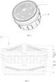
FIG. 1 illustrates a diagrammatic view of a structure of a micro-bubble bubbler inEmbodiment 1; -
FIG. 2 illustrates a sectional view of the micro-bubble bubbler inEmbodiment 1; -
FIG. 3 illustrates a diagrammatic view of an exploded structure of the micro-bubble bubbler inEmbodiment 1; -
FIG. 4 illustrates a top view of the micro-bubble bubbler inEmbodiment 1; -
FIG. 5 illustrates a bottom view of the micro-bubble bubbler inEmbodiment 1; -
FIG. 6 illustrates a diagrammatic view of a structure illustrating a bubble cutting component in the micro-bubble bubbler inEmbodiment 1; -
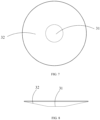
FIG. 7 illustrates a first diagrammatic view of a structure of the bubble cutting component in the micro-bubble bubbler inEmbodiment 1; -
FIG. 8 illustrates a second diagrammatic view of the structure of the bubble cutting component in the micro-bubble bubbler inEmbodiment 1; -
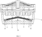
FIG. 9 illustrates a diagrammatic view of a structure illustrating a bubble cutting component in a micro-bubble bubbler inEmbodiment 2; -
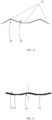
FIG. 10 illustrates a first diagrammatic view of a structure of the bubble cutting component in the micro-bubble bubbler inEmbodiment 2; -
FIG. 11 illustrates a second diagrammatic view of the structure of the bubble cutting component in the micro-bubble bubbler inEmbodiment 2; -
FIG. 12 illustrates a diagrammatic view of a structure illustrating a bubble cutting component in a micro-bubble bubbler inEmbodiment 3; -
FIG. 13 illustrates a first diagrammatic view of a structure of the bubble cutting component in the micro-bubble bubbler inEmbodiment 3; -
FIG. 14 illustrates a second diagrammatic view of the structure of the bubble cutting component in the micro-bubble bubbler inEmbodiment 3; -
FIG. 15 illustrates a diagrammatic view of a structure of a bubble cutting component in a micro-bubble bubbler inEmbodiment 4. - Reference numbers are described as follows:
-
First chamber 100; second chamber 200; -
Filter component 1; air-water mixing component 2;bubble cutting component 3;water outlet cover 4; -
Diverter 21; firstwater inlet hole 211; -
Mixer 22; second water inlet hole 221; -
Impurity discharge passage 31;concave structure 32; protrudingstructure 33;filter screen 34. - The technical solutions in the embodiments of the present disclosure will be described clearly and completely in combination with the accompanying drawings in the embodiments of the present disclosure. The cited embodiments described in the specification are merely used for descriptive purposes and are not used to limit the protection scope of the present disclosure, and therefore, it should be understood that various modifications and variations of the cited embodiments can be made without departing from the protection scope of the present disclosure.
- In the description of the present disclosure, unless otherwise expressly specified and limited, the terms "first" and "second" are merely used for the descriptive purposes and should not be understood as indicating or implying relative importance; and the term "plurality" refers to two or more; and the term "and/or" comprises any combination and all combinations of one or more related listed items. In particular, the reference to "the/said" object or "one" object is also intended to indicate a possible one of a plurality of such objects.
- Unless otherwise expressly specified and limited, it is noted that the terms "connected", "fixed", should develop a broad understanding, for example, "connected" can be a fixed connection, or a detachable connection, or an integrated connection, or an electrical connection, or a signal connection; and "connected" can be a direct connection, or an indirect connection via an intermediate medium. The specific meaning of the terms in the present disclosure can be understood in specific conditions for person of skill in the art.
- Further, in the description of the present disclosure, it should be understood that the directional terms, such as "upper", "lower", "inner", and "outer" described in the cited embodiments of the present disclosure are described according to angles shown in the accompanying drawings and should not be understood as limitations of the cited embodiments of the present disclosure. It should also be understood that, in the context, when an element or feature is mentioned to be connected to "upper", "lower", or "inner", "outer" of another (one or more) element, it can not only be directly connected to "upper", "lower", or "inner", "outer" of another (one or more) elements, but can be also indirectly connected to "upper", "lower", or "inner", "outer" of another (one or more) elements through an intermediate element.
- An embodiment of the present disclosure provides a micro-bubble bubbler, referring to
FIGS. 1-3 , the micro-bubble bubbler comprises afilter component 1, an air-water mixing component 2 and abubble cutting component 3, thefilter component 1 is used to filter water flow, the air-water mixing component 2 is used to convert the water flow into bubble water, a water outlet direction of the air-water mixing component 2 is a first direction, and thebubble cutting component 3 is used to cut bubbles in the bubble water into tiny bubbles to form micro-bubble water. - The micro-bubble bubbler provided in this embodiment achieves a primary filtration of the water flow flowing along a water flow direction to prevent impurities from entering into the micro-bubble bubbler by setting the
filter component 1. Air is introduced into the air-water mixing component 2 to be mixed with the water flow to generate the bubbles to form the bubble water by setting the air-water mixing component 2. Thebubble cutting component 3 is configured to cut the bubbles in the bubble water into the tiny bubbles to form the micro-bubble water by setting thebubble cutting component 3, so that the micro-bubble water takes away dirt in pores or fruits and vegetables by the tiny bubbles, thereby improving cleanliness. - In order to avoid a clogging risk caused by impurities left on the
bubble cutting component 3 when thebubble cutting component 3 cuts the bubble water, thereby affecting a service life of thebubble cutting component 3. Therefore, referring toFIGS. 2 and3 , at least part of thebubble cutting component 3 provided in this embodiment forms an angle with the first direction, and thebubble cutting component 3 comprises animpurity discharge passage 31 along the water flow direction, and theimpurity discharge passage 31 is used to discharge the impurities in the micro-bubble water. Therein, the angle is less than 90 degrees or greater than 90 degrees. - The micro-bubble bubbler provided in this embodiment forms an angle with the first direction through at least part of the
bubble cutting component 3, the angle is less than 90 degrees or greater than 90 degrees, thebubble cutting component 3 is obliquely disposed instead of being horizontally disposed, if the impurities are left on thebubble cutting component 3, thebubble cutting component 3 acts as a guiding slope, when high-speed spraying water flow is sprayed, the impurities will slide down along thebubble cutting component 3 until sliding to a bottom position of thebubble cutting component 3 along the water flow direction, that is, the impurities will accumulate at the bottom position of thebubble cutting component 3 instead of spreading throughout the entirebubble cutting component 3, thereby reducing the clogging risk of the entirebubble cutting component 3. At the same time, in order to prevent the impurities of the micro-bubble bubbler from being left on thebubble cutting component 3, thebubble cutting component 3 comprises theimpurity discharge passage 31, and theimpurity discharge passage 31 provides a passage for discharging the impurities to discharge the impurities from an inner side of the micro-bubble bubbler. - It can be understood that the
impurity discharge passage 31 is disposed along the water flow direction, so that theimpurity discharge passage 31 and a flow direction of the water flow are in the same direction, and spray of the water flow provides power for a movement of the impurities, so that the impurities are smoothly discharged from theimpurity discharge passage 31, and impurity discharging effects are good. - It should be particularly noted that if the water flow direction is a vertical direction, the water outlet direction of the air-
water mixing component 2 can be the vertical direction or have a certain angle with the vertical direction, it can be understood that when the water outlet direction of the air-water mixing component 2 is the vertical direction, that is, the water flow direction is the first direction, a second direction can be specifically a horizontal direction, at this time, the first direction and the second direction are arranged perpendicular to each other, as shown inFIG. 2 , an arrow direction X represents the first direction, and an arrow direction Y represents the second direction. Therein, thefilter component 1, the air-water mixing component 2 and thebubble cutting component 3 are arranged along the water flow direction, that is, thefilter component 1, the air-water mixing component 2 and thebubble cutting component 3 are arranged in sequence from top to bottom. - In an embodiment, as shown in
FIGS. 2-4 , thefilter component 1 comprises a support member and a filter member, the support member is an annular structure, the support member is used to install and support the filter member, and the filter member is a filter screen structure. Therein, the filter member is at least partially obliquely disposed relative to the second direction. - In this solution, the filter member is obliquely disposed, if the impurities left on the filter member is too much, the filter member acts as a guiding slope, when the high-speed spraying water flow is sprayed, the impurities will slide down along the filter member until sliding to a bottom position of the filter member along the water flow direction, that is, the impurities will accumulate at the bottom position of the filter member instead of spreading throughout the entire filter member, reducing a clogging risk of the entire filter member. The filter member can also be disposed horizontally, and the micro-bubble bubbler can be detached for washing the impurities accumulated on the filter member. The micro-bubble bubbler can also be provided without the filter member.
- In an embodiment, as shown in
FIGS. 2 ,3 and5 , the micro-bubble bubbler further comprises awater outlet cover 4, thefilter component 1 is disposed upstream of the air-water mixing component 2 along the water flow direction, and thebubble cutting component 3 is disposed between thewater outlet cover 4 and the air-water mixing component 2. - The primary filtration of the water flow flowing along the water flow direction is achieved to prevent larger impurities from entering into the micro-bubble bubbler by setting the
filter component 1 upstream of the air-water mixing component 2 along the water flow direction. Thebubble cutting component 3 is disposed between thewater outlet cover 4 and the air-water mixing component 2, that is, thewater outlet cover 4 is disposed downstream of thebubble cutting component 3 along the water flow direction for water outflow with the tiny bubbles. - It should be particularly noted that the
water outlet cover 4 comprises water outlet holes, the water outlet holes are in communication with theimpurity discharge passage 31, so that the impurities flowing out of theimpurity discharge passage 31 are discharged through the water outlet holes, and the water outlet hole provides a discharging space for finally discharging the impurities, avoiding a blockage of theimpurity discharge passage 31, so as to ensure a cleanliness inside of the micro-bubble bubbler. - In an embodiment, as shown in
FIGS. 2 and3 , the air-water mixing assembly 2 comprises adiverter 21 and amixer 22. Thewater outlet cover 4 is buckled to themixer 22 and thediverter 21, and an air inlet flow passage is formed between a side wall of themixer 22 and a side wall of thediverter 21, and the air inlet flow passage is in communication with afirst chamber 100. A second chamber 200 is formed between thewater outlet cover 4 and themixer 22, and thebubble cutting component 3 is disposed in the second chamber 200. Alternatively, the air inlet flow passage can be formed between a side wall of thewater outlet cover 4 and the side wall of thediverter 21. - The water flow flows through a first
water inlet hole 211 and a second water inlet hole 221 in sequence, as a flowing area of the second water inlet hole 221 is larger than a flowing area of the firstwater inlet hole 211, according to the Bernoulli equation, a preset negative pressure will be generated in the second water inlet hole 221, so that external air passes through the air inlet flow passage and thefirst chamber 100 in sequence and is sucked into the second water inlet hole 221 to form mixed water flow having preset bubbles with the water flow, and the mixed water flow enters into the second chamber 200. - In an embodiment, as shown in
FIG.6 , theimpurity discharge passage 31 is disposed on a position of thebubble cutting component 3 farthest from the air-water mixing component 2 along the water flow direction. - By setting the
impurity discharge passage 31 on the position of thebubble cutting component 3 farthest from the air-water mixing component 2, that is, theimpurity discharge passage 31 is equivalent to be disposed on the bottom position of thebubble cutting component 3 along the water flow direction, as the impurities will slide down along thebubble cutting component 3 until sliding to the bottom position of thebubble cutting component 3 along the water flow direction, so that theimpurity discharge passage 31 can just catches the impurities sliding down, that is, the impurities directly face theimpurity discharge passage 31, ensuring all of the impurities to enter into theimpurity discharge passage 31, under flushing of the high-speed spraying water flow, the impurities are more easily to flush into theimpurity discharge passage 31, thereby achieving a process for discharging the impurities. - In an embodiment, as shown in
FIG.6 , thebubble cutting component 3 is concave in a direction away from the air-water mixing component 2 to form aconcave structure 32 along the water flow direction. - The
bubble cutting component 3 is concave in the direction away from the air-water mixing component 2, for example, the formedconcave structure 32 is a horn-shaped structure, a large opening end of the horn-shaped structure faces the air-water mixing component 2, and a small opening end of the horn-shaped structure faces thewater outlet cover 4. At this time, two side walls of theconcave structure 32 are obliquely disposed relative to the second direction, so that the impurities can slide along a groove wall that is obliquely disposed, and theconcave structure 32 serves to accumulate the impurities. It can be understood that the impurities are accumulated to a groove bottom of theconcave structure 32 along the groove wall without spreading throughout the entire side walls, avoiding blockage of the groove wall of theconcave structure 32 in a large scale. - In an embodiment, the
impurity discharge passage 31 is disposed at a maximum-groove-depth position of theconcave structure 32 along the water flow direction. - It is equivalent that the
impurity discharge passage 31 is disposed on a position of the groove bottom of theconcave structure 32 by setting theimpurity discharge passage 31 on the maximum-groove-depth position of theconcave structure 32, as a large amount of the impurities are accumulated to the groove bottom of theconcave structure 32 along the groove wall of theconcave structure 32, theimpurity discharge passage 31 just directly faces a position where the impurities are accumulated in thebubble cutting component 3, ensuring the impurities to be directly discharged from theimpurity discharge passage 31. - It can be understood that if the
concave structure 32 is a symmetric structure relative to an axis of a micro-bubble component, at this time, theimpurity discharge passage 31 is disposed on a center position of theconcave structure 32 along the second direction, which is equivalent to set theimpurity discharge passage 31 adjacent to an accumulated point. - It can be understood that in some embodiments, the
concave structure 32 can also be an asymmetric structure relative to the axis of the micro-bubble component, at this time, theimpurity discharge passage 31 merely needs to be disposed at a lowest point of theconcave structure 32 along the water flow direction. - In an embodiment, as shown in
FIGS. 6-8 , theimpurity discharge passage 31 is a through hole disposed on thebubble cutting component 3. Theimpurity discharge passage 31 can be formed by directly forming the through hole on thebubble cutting component 3, a structure is simple, is easy to implement, and has a relatively low cost for a production process. - Specifically, a shape of a cross section of the through hole is any one of a circle, an arc, a triangle and a polygon. In this embodiment, a specific shape of the through hole, i.e., the
impurity discharge passage 31, is not limited and can be adjusted according to actual production needs. - It can be understood that the
impurity discharge passage 31 disposed on theconcave structure 32 can be a circular hole structure, so that the impurities along a circumferential direction of thebubble cutting component 3 are evenly accumulated to the center position. - It should be noted that the
concave structure 32 and thewater outlet cover 4 surround to form a conical structure, a cross section of the conical structure is a triangular structure, and at this time, the maximum-groove-depth position of theconcave structure 32 along the water flow direction is a position where theconcave structure 32 and thewater outlet cover 4 contact each other; and theconcave structure 32 and thewater outlet cover 4 surround to form a structure with a cross section as a frustum, a minimum-height position of theconcave structure 32 along the water flow direction is a bottom surface of the structure shaped in the frustum along the water flow direction, and at this time, the bottom surface can provide a supporting force for thebubble cutting component 3 from thewater outlet cover 4 and can provide a larger installation space for theimpurity discharge passage 31. - In an embodiment, as shown in
FIG. 9 , thebubble cutting component 3 protrudes in a direction adjacent to the air-water mixing component 2 to form a protrudingstructure 33 along the water flow direction. - The
bubble cutting component 3 protrudes in the direction adjacent to the air-water mixing component 2, for example, the formed protrudingstructure 33 is a horn-shaped structure, a large opening end of the horn-shaped structure faces thewater outlet cover 4, and a small opening end of the horn-shaped structure faces the air-water mixing component 2. At this time, two side walls of the protrudingstructure 33 are obliquely disposed relative to the second direction, so that the impurities can slide along the side walls that are obliquely disposed, and the protrudingstructure 33 serves to disperse the impurities. It can be understood that the impurities are dispersed to a bottom of the protrudingstructure 33 along the side walls without spreading throughout the entire side walls, avoiding blockage of the side walls of the protrudingstructure 33 in a large scale. - In an embodiment, as shown in
FIGS. 9-11 , one or moreimpurity discharge passages 31 are disposed at the minimum-height position of the protrudingstructure 33 along the water flow direction. - It is equivalent that the one or more
impurity discharge passages 31 are disposed on a position at an edge of the protrudingstructure 33 by setting the one or moreimpurity discharge passages 31 on the minimum-height position of the protrudingstructure 33, as a large amount of the impurities are dispersed to the edge of the protrudingstructure 33 along the side walls of the protrudingstructure 33, the one or moreimpurity discharge passages 31 just face a position where the impurities are dispersed in thebubble cutting component 3, ensuring the impurities to be directly discharged from the one or moreimpurity discharge passages 31. - It should be understood that if the protruding
structure 33 is a symmetrical structure relative to the axis of the micro-bubble component, at this time, the one or moreimpurity discharge passages 31 are disposed on a position of the protrudingstructure 33 farthest from a center thereof along the second direction, which is equivalent that the one or moreimpurity discharge passages 31 are disposed on a position adjacent to the dispersed point. - It should be understood that in some embodiments, the protruding
structure 33 can also be an asymmetrical structure relative to the axis of the micro-bubble component, and at this time, the one or moreimpurity discharge passages 31 merely need to be disposed at a lowest point of the protrudingstructure 33 along the water flow direction. - It should be understood that, as shown in
FIGS. 9-11 , the one or moreimpurity discharge passages 31 disposed on the protrudingstructure 33 can be one or more arc-shaped hole structures, such as one or more semi-circular hole structures, it is equivalent that the edge of thebubble cutting component 3 extends inward to form the one or more semi-circular hole structures, so that the impurities are evenly dispersed to the position of the edge of thebubble cutting component 3 along the circumferential direction. A number of the one or moreimpurity discharge passages 31 can be multiple, and multiple of the one or moreimpurity discharge passages 31 are evenly disposed along an axial direction of thebubble cutting component 3 to ensure uniformity in dispersing the impurities. - It should be noted that the protruding
structure 33 and thewater outlet cover 4 surround to form a conical structure, a cross section of the conical structure is a triangular structure, at this time, a minimum-height position of the protrudingstructure 33 along the water flow direction is a position where the protrudingstructure 33 and thewater outlet cover 4 contact each other, and the protrudingstructure 33 and thewater outlet cover 4 can also surround to define a structure with a cross section as a pentagon, at this time, the minimum-height position of the protrudingstructure 33 along the water flow direction is a lower end position of the side walls of the protrudingstructure 33. - In an embodiment, as shown in
FIGS. 12-14 , thebubble cutting component 3 is concave in the direction away from the air-water mixing component 2 along the water flow direction to form one or moreconcave structures 32, and thebubble cutting component 3 protrudes in the direction adjacent to the air-water mixing component 2 to form one or moreprotruding structures 33. - In other words, the
bubble cutting component 3 comprises not only the one or moreconcave structures 32, or thebubble cutting component 3 comprises not only the one or moreprotruding structures 33, thebubble cutting component 3 can comprise the one or moreconcave structures 32 and the one or moreprotruding structures 33 synchronously, as one or more groove walls of the one or moreconcave structures 32 and one or more side walls of the one or moreprotruding structures 33 are both obliquely disposed relative to the second direction, thus ensuring smoothness and reliability of downward sliding of the impurities. - It can be understood that if a number of the one or more
protruding structures 33 and the one or moreconcave structures 32 is one, a cross section of thebubble cutting component 3 forms a folded line structure. - In an embodiment, the protruding
structure 33 and theconcave structure 32 adjacent to it are at least partially overlapped. - With respect to the protruding
structure 33 and theconcave structure 32 that are adjacent, the protrudingstructure 33 and theconcave structure 32 will have a common inclined surface, that is, the side walls of the protrudingstructure 33 are just the groove wall of theconcave structure 32. - In an embodiment, as shown in
FIGS. 12-14 , theconcave structure 32 is coaxially disposed relative to the air-water mixing component 2, and the protrudingstructure 33 is disposed around a periphery of theconcave structure 32; or, as shown inFIG. 15 , the protrudingstructure 33 is coaxially disposed relative to the air-water mixing component 2, and theconcave structure 32 is disposed around a periphery of the protrudingstructure 33. - As shown in
FIGS. 12-14 , by coaxially setting theconcave structure 32 relative to the air-water mixing component 2, the protrudingstructure 33 is disposed around the periphery of theconcave structure 32, and that is, theconcave structure 32 is disposed at a center position of thebubble cutting component 3. When thebubble cutting component 3 is symmetrical relative to an axis of the air-water mixing component 2, with respect to a half side of thebubble cutting component 3, it is equivalent to divide a radius of thebubble cutting component 3 into two parts, so that the two parts have two inclined side walls of the protrudingstructure 33, so as to achieve a segmented treatment of a radius part of thebubble cutting component 3, a time is saved for the impurities on a top of thebubble cutting component 3 to slide to a bottom along the water flow direction, and timeliness and effectiveness of discharging the impurities is improved. - As shown in
FIG. 15 , by coaxially setting the protrudingstructure 33 relative to the air-water mixing component 2, theconcave structure 32 is disposed around the periphery of the protrudingstructure 33, and that is, the protrudingstructure 33 is disposed at a center position of thebubble cutting component 3. When thebubble cutting component 3 is symmetrical relative to an axis of the air-water mixing component 2, with respect to a half side of thebubble cutting component 3, it is equivalent to divide a radius of thebubble cutting component 3 into two parts, so that the two parts have two inclined groove walls of a groove structure, so as to achieve a segmented treatment of a radius part of thebubble cutting component 3, a time is saved for the impurities on the top of thebubble cutting component 3 to slide to a bottom along the water flow direction, and timeliness and effectiveness of discharging the impurities is improved. - In an embodiment, the one or more
impurity discharge passages 31 are disposed on the center position of theconcave structure 32 along the second direction; and/or, the one or moreimpurity discharge passages 31 are disposed at a position of the protrudingstructure 33 farthest from a center thereof along the second direction. - As shown in
FIGS. 12-14 , when theconcave structure 32 is coaxially disposed relative to the air-water mixing component 2, that is, theconcave structure 32 is disposed on the center position of thebubble cutting component 3, the one or moreimpurity discharge passages 31 are disposed on the center position of theconcave structure 32, it is equivalent that the one or moreimpurity discharge passages 31 are disposed on a maximum-groove-depth position of theconcave structure 32, as the large amount of the impurities accumulated to the groove bottom of theconcave structure 32 along the groove wall of theconcave structure 32, the one or moreimpurity discharge passages 31 just directly face the position where the impurities are accumulated in thebubble cutting component 3, ensuring the impurities to be directly discharged from the one or moreimpurity discharge passages 31. - When the
concave structure 32 is coaxially disposed relative to the air-water mixing component 2, the protrudingstructure 33 is disposed around the periphery of theconcave structure 32, as the one or moreimpurity discharge passages 31 are disposed on the position of the protrudingstructure 33 farthest from the center thereof, that is, the one or moreimpurity discharge passages 31 are disposed at a minimum-height position of the protrudingstructure 33, it is equivalent that the one or moreimpurity discharge passages 31 are disposed on a position of an edge of the protrudingstructure 33, as the large amount of the impurities are dispersed to the edge of the protrudingstructure 33 along the side walls of the protrudingstructure 33, the one or moreimpurity discharge passages 31 just directly face the position where the impurities are dispersed in thebubble cutting component 3, ensuring the impurities to be directly discharged from the one or moreimpurity discharge passages 31. - As shown in
FIG. 15 , when the protrudingstructure 33 is coaxially disposed relative to the air-water mixing component 2, that is, the protrudingstructure 33 is disposed on the center position of thebubble cutting component 3, as the one or moreimpurity discharge passages 31 are disposed on the position of the protrudingstructure 33 farthest from the center thereof, that is, the one or moreimpurity discharge passages 31 are disposed on the minimum-height position of the protrudingstructure 33, it is equivalent that the one or moreimpurity discharge passages 31 are disposed on the position of the edge of the protrudingstructure 33, as the large amount of the impurities are dispersed to the edge of the protrudingstructure 33 along the side walls of the protrudingstructure 33, the one or moreimpurity discharge passages 31 just directly face the position where the impurities are dispersed in thebubble cutting component 3, ensuring the impurities to be directly discharged from the one or moreimpurity discharge passages 31. - The protruding
structure 33 and the air-water mixing component 2 are coaxially disposed, theconcave structure 32 is disposed around the periphery of the protrudingstructure 33, as the one or moreimpurity discharge passages 31 are disposed at the center position of theconcave structure 32, it is equivalent that the one or moreimpurity discharge passages 31 are disposed on the maximum-groove-depth position of theconcave structure 32, as the large amount of the impurities are accumulated to the groove bottom of theconcave structure 32 along the groove wall of theconcave structure 32, the one or moreimpurity discharge passages 31 just directly face the position where the impurities are accumulated in thebubble cutting component 3, ensuring the impurities to be directly discharged from the one or moreimpurity discharge passages 31. - It can be understood that in this case, a number and a position of the one or more
impurity discharge passages 31 can be one or more, one of the one or moreimpurity discharge passages 31 can be merely disposed at the center position of theconcave structure 32, or the one of the one or moreimpurity discharge passages 31 can be merely disposed at the position of the protrudingstructure 33 farthest from the center thereof, or multiple of the one or moreimpurity discharge passages 31 are respectively disposed at the center position of theconcave structure 32 and the position of the protrudingstructure 33 farthest from the center thereof. - In an embodiment, a number of the one or more
protruding structures 33 is multiple, and theconcave structure 32 is disposed between two adjacent ones of the one or moreprotruding structures 33; and/or, a number of the one or moreconcave structures 32 is multiple, and the protrudingstructure 33 is disposed between two adjacent ones of the one or moreconcave structures 32. - It can be understood that numbers of the one or more
protruding structures 33 and the one or moreconcave structures 32 can both be multiple, the one or moreprotruding structures 33 and the one or moreconcave structures 32 are mutually nested, and radii of the one or moreprotruding structures 33 and the one or moreconcave structures 32 are different. At this time, a cross section of thebubble cutting component 3 is similar to a continuous folded line structure, ensuring the impurities to be not temporarily left on the top of thebubble cutting component 3, and all of the impurities will slide to a bottom of thebubble cutting component 3. - It can be understood that when a radius of the
bubble cutting component 3 is a preset value, when the numbers of the one or moreprotruding structures 33 and the one or moreconcave structures 32 are more, the angles of the one or moreprotruding structures 33 and the one or moreconcave structures 32 inclined along the second direction becomes smaller, that is, slopes of inclined surfaces are slower, which is possible to affect a sliding speed of the impurities, therefore, the number of the one or moreprotruding structures 33, the number of the one or moreconcave structures 32, and slopes of the one or moreprotruding structures 33 and slopes of the one or moreconcave structures 32 can be selected according to actual needs, so that the number and the slopes are in a preset balance correlation, thereby ensuring the timeliness of discharging the impurities. - In an embodiment, a projection of the air-
water mixing component 2 at least partially covers a projection of thebubble cutting component 3 along the water flow direction. - As the projection of the
bubble cutting component 3 is covered by the projection of the air-water mixing component 2, the micro-bubble water discharged by the air-water mixing component 2 can directly pass through thebubble cutting component 3 to achieve filtration of the impurities while ensuring the micro-bubble component to directly face thebubble cutting component 3. - In an embodiment, the
bubble cutting component 3 comprises a plurality of filter screens 34 stacked along the water flow direction; therein, in the plurality of filter screens 34, at least some of the filter screens 34 have different mesh numbers. Afilter screen 34 located at a top layer along the water flow direction has a largest mesh number; and thefilter screen 34 located at the top layer along the water flow direction has a mesh number greater than or equal to 200 meshes. - For example, some of the filter screens 34, i.e., the
filter screen 34 located at the top layer along the water flow direction, can be one or more filter screens with sparse pores, and some of the filter screens 34, i.e., afilter screen 34 below thefilter screen 34 located at the top layer, can be one or more filter screens with dense pores, and multiple of the one or more filter screens with sparse pores and multiple of the one or more filter screens with the dense pores form thebubble cutting component 3 with a pattern of alternating sparseness and density that are alternately stacked, and effects of cutting the bubbles are improved. - This embodiment further provides a water outlet device, which is suitable for the technical arts of showers, faucets, and toilets, and the water outlet device comprises the micro-bubble bubbler.
- The water outlet device provided in this embodiment achieves the primary filtration of the water flow flowing along the water flow direction to prevent the impurities from entering into the micro-bubble bubbler by setting the
filter component 1; the air is introduced into the air-water mixing component 2 and mixed with the water flow to generate the bubbles to form the bubble water by setting the air-water mixing component 2; and the bubbles in the bubble water are cut into the tiny bubbles to form the micro-bubble water by setting thebubble cutting component 3, so that the micro-bubble water takes away the dirt in the pores or the fruits and vegetables by the tiny bubbles, thereby improving cleanliness. - At the same time, at least part of the
bubble cutting component 3 forms the angle with the first direction, the angle is less than 90 degrees or greater than 90 degrees, thebubble cutting component 3 is obliquely disposed instead of being horizontally disposed, if the impurities on thebubble cutting component 3 are left on thebubble cutting component 3, thebubble cutting component 3 acts as the guiding slope, when the high-speed spraying water flow is sprayed, the impurities will slide down along thebubble cutting component 3 until sliding to the bottom position of thebubble cutting component 3 along the water flow direction, that is, the impurities will be accumulated at the bottom position of thebubble cutting component 3 instead of spreading throughout the entirebubble cutting component 3, thereby reducing the clogging risk of holes of the filter screens of the entirebubble cutting component 3. At the same time, as the impurities in the micro-bubble water will be left on thebubble cutting component 3, by setting the one or moreimpurity discharge passages 31 on thebubble cutting component 3, the one or moreimpurity discharge passages 31 provide a passage for discharging the impurities to discharge the impurities from an inner side of the micro-bubble bubbler; by setting the one or moreimpurity discharge passages 31 along the water flow direction, the one or moreimpurity discharge passages 31 and the flow direction of the water flow are in the same direction, and the water flow sprays to provide power from a movement of the impurities, so that the impurities are smoothly discharged from the one or moreimpurity discharge passages 31, an effects of discharging the impurity are good. - In an embodiment, the water outlet device further comprises a water inlet pipe, the water inlet pipe is in communication with the micro-bubble bubbler, and the water inlet pipe is used to supply the water flow to the micro-bubble bubbler.
- Other embodiments of the present disclosure are easily thought out by person of skill in the technical art after considering the inventions disclosed in the specification and the practice herein. It is intended that the present disclosure covers any modifications, uses or adaptive variations of the present disclosure, these modifications, uses or adaptive variations follow general principles of the present disclosure and comprise the common knowledge or the conventional technical methods in the technical art and not disclosed in the present disclosure. It is intended that the specification and the cited embodiments are merely considered as examples, and an exact scope and a spirit of the present disclosure are defined by the accompanying claims.
- It should be understood that the present disclosure is not limited to the exact structure described above and illustrated the accompanying drawings and can be modified and varied without departing from the scope thereof. The protective scope of the present disclosure is merely limited by the accompanying claims.
Claims (16)
- A micro-bubble bubbler, characterized in that, it comprises:a filter component (1) for filtering water flow;an air-water mixing component (2) for converting the water flow into bubble water, and a water outlet direction of the air-water mixing component is a first direction;a bubble cutting component (3) for cutting the bubble water so as to cut bubbles in the bubble water into tiny bubbles to form micro-bubble water;at least part of the bubble cutting component (3) forms an angle with the first direction, and the bubble cutting component (3) comprises one or more impurity discharge passages (31), and the one or more impurity discharge passages (31) are used to discharge impurities; andthe angle is not equal to 90 degrees.
- The micro-bubble bubbler according to claim 1, characterized in that, the one or more impurity discharge passages (31) are disposed at one or more positions of the bubble cutting component (3) farthest from the air-water mixing component (2) along the water flow direction.
- The micro-bubble bubbler according to claim 1, characterized in that, the bubble cutting component (3) is concave in a direction away from the air-water mixing component (2) to form one or more concave structures (32) along the water flow direction.
- The micro-bubble bubbler according to claim 3, characterized in that, the one or more impurity discharge passages (31) are disposed at one or more maximum-groove-depth positions of the one or more concave structures (32) along the water flow direction.
- The micro-bubble bubbler according to claim 1, characterized in that, the bubble cutting component (3) protrudes in a direction adjacent to the air-water mixing component (2) to form one or more protruding structures (33).
- The micro-bubble bubbler according to claim 5, characterized in that, the one or more impurity discharge passages (31) are disposed on one or more minimum-height positions of the one or more protruding structures (33) along the water flow direction.
- The micro-bubble bubbler according to claim 1, characterized in that, the bubble cutting component (3) is concave in a direction away from the air-water mixing component (2) to form one or more concave structures (32) along the water flow direction, and the bubble cutting component (3) protrudes in a direction adjacent to the air-water mixing component (2) to form one or more protruding structures (33).
- The micro-bubble bubbler according to claim 7, characterized in that, the one or more concave structures (32) are coaxially arranged relative to the air-water mixing component (2), and the one or more protruding structure (33) are disposed around one or more peripheries of the one or more concave structures (32); or,
the one or more protruding structures (33) are coaxially arranged relative to the air-water mixing component (2), and the one or more concave structures (32) are disposed around one or more peripheries of the one or more protruding structures (33). - The micro-bubble bubbler according to claim 8, characterized in that, the one or more impurity discharge passages (31) are disposed at one or more centers of the one or more concave structures (32); and/or,
the one or more impurity discharge passages (31) are disposed at one or more positions of the one or more protruding structures (33) farthest from one or more centers thereof. - The micro-bubble bubbler according to claim 8, characterized in that, the number of the one or more protruding structures (33) is multiple, and the one or more concave structures (32) are disposed between two adjacent ones of the one or more protruding structures (33); and/or,
the number of the one or more concave structures (32) are multiple, and the one or more protruding structures (33) are disposed between two adjacent ones of the one or more concave structures (32). - The micro-bubble bubbler according to claim 7, characterized in that, the one or more protruding structures (33) and the one or more concave structures (32) adjacent thereof are at least partially overlapped.
- The micro-bubble bubbler according to any of claims 1-11, characterized in that, the one or more impurity discharge passages (31) are one or more through holes disposed on the bubble cutting component (3).
- The micro-bubble bubbler according to claim 12, characterized in that, a cross section of a through hole is any one of a circle, an arc, a triangle and a polygon.
- The micro-bubble bubbler according to any of claims 1-11, wherein the bubble cutting component (3) comprises a plurality of filter screens (34) that are stacked along the water flow direction;wherein, at least some filter screens (34) in the plurality of filter screens (34) have different mesh numbers; a filter screen (34) at a top along the water flow direction has a largest mesh number; andthe mesh number of the filter screen (34) at the top along the water flow direction is larger than and equal to 200 meshes.
- The micro-bubble bubbler according to claim 1, characterized in that, it further comprises a water outlet cover (4), the filter component (1) is disposed upstream of the air-water mixing component (2) along the water flow direction; and the bubble cutting component (3) is disposed between the water outlet cover (4) and the air-water mixing component (2).
- A water outlet device, characterized in that, it comprises the micro-bubble bubbler according to any one of claims 1-15.
Applications Claiming Priority (2)
| Application Number | Priority Date | Filing Date | Title |
|---|---|---|---|
| CN202210626316.6A CN117211374A (en) | 2022-06-02 | 2022-06-02 | A microbubble bubbler and water outlet device |
| PCT/CN2023/094892 WO2023231786A1 (en) | 2022-06-02 | 2023-05-17 | Microbubble bubbler and water outlet apparatus |
Publications (2)
| Publication Number | Publication Date |
|---|---|
| EP4534767A1 true EP4534767A1 (en) | 2025-04-09 |
| EP4534767A4 EP4534767A4 (en) | 2026-05-13 |
Family
ID=89026936
Family Applications (1)
| Application Number | Title | Priority Date | Filing Date |
|---|---|---|---|
| EP23814971.0A Pending EP4534767A4 (en) | 2022-06-02 | 2023-05-17 | Microbubble aerator and water outlet device |
Country Status (4)
| Country | Link |
|---|---|
| EP (1) | EP4534767A4 (en) |
| JP (1) | JP2025519236A (en) |
| CN (1) | CN117211374A (en) |
| WO (1) | WO2023231786A1 (en) |
Families Citing this family (1)
| Publication number | Priority date | Publication date | Assignee | Title |
|---|---|---|---|---|
| JP7535349B1 (en) | 2024-01-23 | 2024-08-16 | 株式会社No. | Microbubble Generator |
Family Cites Families (19)
| Publication number | Priority date | Publication date | Assignee | Title |
|---|---|---|---|---|
| GB809362A (en) * | 1955-03-28 | 1959-02-25 | Elie Prodromos Aghnides | Improvements in and relating to water aerators |
| DE3000799A1 (en) * | 1980-01-11 | 1981-07-16 | Dieter Wildfang KG, 7840 Müllheim | JET CONTROLLER FOR CONNECTION TO SANITARY FITTINGS OR THE LIKE. |
| US6513731B2 (en) * | 2001-01-02 | 2003-02-04 | Moen Incorporated | Aerator with variable air input |
| ITMN20040015A1 (en) * | 2004-07-13 | 2004-10-13 | Bpa Srl | FLUX REGULATOR |
| DE102010012326B4 (en) * | 2010-03-23 | 2015-10-01 | Neoperl Gmbh | aerator |
| CN102000520B (en) * | 2010-11-02 | 2012-10-03 | 厦门松霖科技有限公司 | Bubbler and bubbling water discharging method thereof |
| CN203389782U (en) * | 2013-08-06 | 2014-01-15 | 厦门松霖科技有限公司 | Bubbler with independent gas-water mixing holes |
| CN205776572U (en) * | 2016-05-27 | 2016-12-07 | 李军 | Bubbler |
| DE202017105378U1 (en) * | 2017-09-06 | 2018-12-07 | Neoperl Gmbh | aerator |
| CN111821871A (en) * | 2019-09-20 | 2020-10-27 | 山东海普斯舟设备科技有限公司 | A micro-nano bubble generator with compound cutting function |
| CN212215941U (en) * | 2019-12-25 | 2020-12-25 | 厦门英仕卫浴有限公司 | Gondola water faucet that microbubble goes out water |
| CN111167327B (en) * | 2020-01-15 | 2025-01-10 | 厦门松霖科技股份有限公司 | Bubble water generating device |
| EP3851198B1 (en) * | 2020-01-15 | 2023-03-08 | Xiamen Solex High-Tech Industries Co., Ltd. | Device for generating water with air bubbles |
| CN211837316U (en) * | 2020-03-11 | 2020-11-03 | 上海捷乔纳米科技有限公司 | Micro-nano bubble bubbler |
| CN112177108B (en) * | 2020-10-27 | 2025-04-11 | 福建省德牧卫浴科技有限公司 | A side-entry bubbler |
| TWM614629U (en) * | 2021-01-28 | 2021-07-21 | 歐陽家宏 | Microbubble bubbler |
| CN215330244U (en) * | 2021-05-19 | 2021-12-28 | 九牧厨卫股份有限公司 | Foaming device |
| CN215406329U (en) * | 2021-05-19 | 2022-01-04 | 九牧厨卫股份有限公司 | Multifunctional bubbler |
| CN217352737U (en) * | 2022-06-02 | 2022-09-02 | 厦门松霖科技股份有限公司 | Microbubble bubbler and water outlet device |
-
2022
- 2022-06-02 CN CN202210626316.6A patent/CN117211374A/en active Pending
-
2023
- 2023-05-17 JP JP2024571048A patent/JP2025519236A/en active Pending
- 2023-05-17 EP EP23814971.0A patent/EP4534767A4/en active Pending
- 2023-05-17 WO PCT/CN2023/094892 patent/WO2023231786A1/en not_active Ceased
Also Published As
| Publication number | Publication date |
|---|---|
| WO2023231786A1 (en) | 2023-12-07 |
| EP4534767A4 (en) | 2026-05-13 |
| CN117211374A (en) | 2023-12-12 |
| JP2025519236A (en) | 2025-06-24 |
Similar Documents
| Publication | Publication Date | Title |
|---|---|---|
| JP2012082591A (en) | Shower head | |
| JP7125991B2 (en) | microbubble generator | |
| EP1273724B1 (en) | Foam water delivery port | |
| US4072270A (en) | Shower head aerator | |
| US3851825A (en) | Leak-proof laminar flow device | |
| CN107743536B (en) | Air-entrained jet regulator with rectifier in the form of a mesh structure | |
| JP6268135B2 (en) | Micro bubble shower device | |
| JPWO2017029835A1 (en) | Foam water discharge device and foam water discharge unit | |
| US11400424B2 (en) | Micro-bubble acquisition apparatus | |
| JP2012072594A (en) | Foamy water discharge device | |
| CN109847607B (en) | Unpowered bubble micronizing device | |
| US20220410190A1 (en) | Microbubble-Producing Water Outlet Assembly | |
| CN117211374A (en) | A microbubble bubbler and water outlet device | |
| CN217352737U (en) | Microbubble bubbler and water outlet device | |
| JP2010142336A (en) | Shower device | |
| JP3837744B1 (en) | shower head | |
| CN220600565U (en) | Two-functional water outlet head and tap | |
| US3130915A (en) | Aerator having an enlarged stream outlet | |
| EP4616956A1 (en) | Water outlet structure, water outlet panel and tap aerator | |
| JP6315248B2 (en) | Water discharge device | |
| JPH03165855A (en) | Water discharging mechanism and foamed water discharging port utilized therewith | |
| US20200406276A1 (en) | Anti-splash water outflow device | |
| CN220633782U (en) | Micro-bubble generator | |
| JP6315247B2 (en) | Water discharge device | |
| US3198440A (en) | Aerator structure and legged diaphragm therefor |
Legal Events
| Date | Code | Title | Description |
|---|---|---|---|
| STAA | Information on the status of an ep patent application or granted ep patent |
Free format text: STATUS: THE INTERNATIONAL PUBLICATION HAS BEEN MADE |
|
| PUAI | Public reference made under article 153(3) epc to a published international application that has entered the european phase |
Free format text: ORIGINAL CODE: 0009012 |
|
| STAA | Information on the status of an ep patent application or granted ep patent |
Free format text: STATUS: REQUEST FOR EXAMINATION WAS MADE |
|
| 17P | Request for examination filed |
Effective date: 20241220 |
|
| AK | Designated contracting states |
Kind code of ref document: A1 Designated state(s): AL AT BE BG CH CY CZ DE DK EE ES FI FR GB GR HR HU IE IS IT LI LT LU LV MC ME MK MT NL NO PL PT RO RS SE SI SK SM TR |
|
| DAV | Request for validation of the european patent (deleted) | ||
| DAX | Request for extension of the european patent (deleted) | ||
| STAA | Information on the status of an ep patent application or granted ep patent |
Free format text: STATUS: EXAMINATION IS IN PROGRESS |
|
| A4 | Supplementary search report drawn up and despatched |
Effective date: 20260414 |
|
| RIC1 | Information provided on ipc code assigned before grant |
Ipc: E03C 1/084 20060101AFI20260408BHEP Ipc: B01F 23/231 20220101ALI20260408BHEP Ipc: B01F 25/312 20220101ALI20260408BHEP Ipc: B01F 25/452 20220101ALI20260408BHEP Ipc: B01D 29/03 20060101ALI20260408BHEP Ipc: B01D 29/90 20060101ALI20260408BHEP |