EP4534750A1 - Apparatus for treating laundry - Google Patents
Apparatus for treating laundry Download PDFInfo
- Publication number
- EP4534750A1 EP4534750A1 EP23824254.9A EP23824254A EP4534750A1 EP 4534750 A1 EP4534750 A1 EP 4534750A1 EP 23824254 A EP23824254 A EP 23824254A EP 4534750 A1 EP4534750 A1 EP 4534750A1
- Authority
- EP
- European Patent Office
- Prior art keywords
- drain hose
- hose
- laundry
- treating device
- treating apparatus
- Prior art date
- Legal status (The legal status is an assumption and is not a legal conclusion. Google has not performed a legal analysis and makes no representation as to the accuracy of the status listed.)
- Pending
Links
Images





Classifications
-
- D—TEXTILES; PAPER
- D06—TREATMENT OF TEXTILES OR THE LIKE; LAUNDERING; FLEXIBLE MATERIALS NOT OTHERWISE PROVIDED FOR
- D06F—LAUNDERING, DRYING, IRONING, PRESSING OR FOLDING TEXTILE ARTICLES
- D06F39/00—Details of washing machines not specific to a single type of machines covered by groups D06F9/00 - D06F27/00
- D06F39/001—Arrangements for transporting, moving, or setting washing machines; Protective arrangements for use during transport
-
- D—TEXTILES; PAPER
- D06—TREATMENT OF TEXTILES OR THE LIKE; LAUNDERING; FLEXIBLE MATERIALS NOT OTHERWISE PROVIDED FOR
- D06F—LAUNDERING, DRYING, IRONING, PRESSING OR FOLDING TEXTILE ARTICLES
- D06F58/00—Domestic laundry dryers
- D06F58/20—General details of domestic laundry dryers
-
- D—TEXTILES; PAPER
- D06—TREATMENT OF TEXTILES OR THE LIKE; LAUNDERING; FLEXIBLE MATERIALS NOT OTHERWISE PROVIDED FOR
- D06F—LAUNDERING, DRYING, IRONING, PRESSING OR FOLDING TEXTILE ARTICLES
- D06F29/00—Combinations of a washing machine with other separate apparatus in a common frame or the like, e.g. with rinsing apparatus
- D06F29/005—Combinations of a washing machine with other separate apparatus in a common frame or the like, e.g. with rinsing apparatus the other separate apparatus being a drying appliance
-
- D—TEXTILES; PAPER
- D06—TREATMENT OF TEXTILES OR THE LIKE; LAUNDERING; FLEXIBLE MATERIALS NOT OTHERWISE PROVIDED FOR
- D06F—LAUNDERING, DRYING, IRONING, PRESSING OR FOLDING TEXTILE ARTICLES
- D06F31/00—Washing installations comprising an assembly of several washing machines or washing units, e.g. continuous flow assemblies
-
- D—TEXTILES; PAPER
- D06—TREATMENT OF TEXTILES OR THE LIKE; LAUNDERING; FLEXIBLE MATERIALS NOT OTHERWISE PROVIDED FOR
- D06F—LAUNDERING, DRYING, IRONING, PRESSING OR FOLDING TEXTILE ARTICLES
- D06F37/00—Details specific to washing machines covered by groups D06F21/00 - D06F25/00
- D06F37/26—Casings; Tubs
- D06F37/261—Tubs made by a specially selected manufacturing process or characterised by their assembly from elements
- D06F37/263—Tubs made by a specially selected manufacturing process or characterised by their assembly from elements assembled from at least two elements connected to each other; Connecting or sealing means therefor
-
- D—TEXTILES; PAPER
- D06—TREATMENT OF TEXTILES OR THE LIKE; LAUNDERING; FLEXIBLE MATERIALS NOT OTHERWISE PROVIDED FOR
- D06F—LAUNDERING, DRYING, IRONING, PRESSING OR FOLDING TEXTILE ARTICLES
- D06F39/00—Details of washing machines not specific to a single type of machines covered by groups D06F9/00 - D06F27/00
- D06F39/08—Liquid supply or discharge arrangements
- D06F39/083—Liquid discharge or recirculation arrangements
-
- D—TEXTILES; PAPER
- D06—TREATMENT OF TEXTILES OR THE LIKE; LAUNDERING; FLEXIBLE MATERIALS NOT OTHERWISE PROVIDED FOR
- D06F—LAUNDERING, DRYING, IRONING, PRESSING OR FOLDING TEXTILE ARTICLES
- D06F39/00—Details of washing machines not specific to a single type of machines covered by groups D06F9/00 - D06F27/00
- D06F39/12—Casings; Tubs
-
- D—TEXTILES; PAPER
- D06—TREATMENT OF TEXTILES OR THE LIKE; LAUNDERING; FLEXIBLE MATERIALS NOT OTHERWISE PROVIDED FOR
- D06F—LAUNDERING, DRYING, IRONING, PRESSING OR FOLDING TEXTILE ARTICLES
- D06F39/00—Details of washing machines not specific to a single type of machines covered by groups D06F9/00 - D06F27/00
- D06F39/12—Casings; Tubs
- D06F39/125—Supporting arrangements for the casing, e.g. rollers or legs
Definitions
- the present disclosure relates to a laundry treating apparatus.
- a laundry treating apparatus is an apparatus that performs necessary processing on laundry, such as placing laundry, for example, clothing or bedding, inside a drum, removing contamination from laundry or drying laundry.
- the laundry treating apparatus When the laundry treating apparatus is provided to remove contamination from laundry, the laundry treating apparatus performs processes such as washing, rinsing, dehydration, and drying.
- the laundry treating apparatus includes a cabinet defining an outer apparatus, a tub accommodated inside the cabinet, a drum rotatably mounted inside the tub and into which laundry is fed, and a detergent supply device that supplies detergent into the drum.
- a detergent supply device that supplies detergent into the drum.
- the laundry treating apparatus When the laundry treating apparatus is configured to dry laundry, the laundry treating apparatus may provide dry air to the laundry and remove moisture from the laundry.
- the laundry treating apparatus includes a cabinet, a drum rotatably provided inside the cabinet, and a heater for heating or drying air provided to laundry. Moisture present in the laundry may be evaporated and removed by dry air, and moisture in the laundry may be removed by supplying the dry air to the laundry contained in the drum.
- a laundry treating apparatus is provided to reduce a floor space by stacking a first treating device (e.g., a washing machine) for washing laundry and a second treating device (e.g., a dryer) for drying laundry and improve user convenience in treating laundry.
- a first treating device e.g., a washing machine
- a second treating device e.g., a dryer
- Cited Reference 1 discloses a laundry treating apparatus including a plurality of treating devices.
- the laundry treating apparatus has a washing machine installed at a lower side and a dryer installed at an upper side.
- Cited Reference 1 discloses a structure in which a washing machine and a dryer are connected to each other at rear sides thereof and have a fastening portion (rear bracket) that provides a handle.
- a front-back depth of the dryer is less than a front-back depth of the washing machine, and thus a step difference is formed at a rear side of the laundry treating apparatus.
- the fastening portion (rear bracket) is the step difference between the washing machine and the dryer and is located above the washing machine to be connected to the laundry treating apparatus.
- it is important to present an efficient arrangement relationship between components and a stable and effective combination relationship between the components for a plurality of treating devices.
- the present disclosure is to provide a structure of a stack-type laundry treating apparatus for ensuring ease of transport.
- the present disclosure is to provide a laundry treating apparatus including a rear bracket provided to support one of two treating devices stacked above each other to be prevented from coming off from the other treating device provided at a lower side.
- the present disclosure is to provide a laundry treating apparatus for improving assembly efficiency by stacking and coupling two treating devices.
- the present disclosure is to provide a laundry treating apparatus for improving coupling performance by stacking and coupling two treating devices.
- the present disclosure is to provide a laundry treating apparatus for effectively coupling two treating devices by stacking the treating devices even when there is no difference between a first treating device and a second treating device.
- the present disclosure is to provide a laundry treating apparatus for providing a structure for effectively and economically fixing a drain hose of a first treating device to a required location according to an installation environment.
- the present disclosure is to provide a laundry treating apparatus configured to prevent a loss of a cap provided in a test port formed in a second treating device.
- a laundry treating apparatus includes a first treating device including a first cabinet including a first rear panel defining a rear surface and a first drum configured to accommodate laundry therein, a second treating device including a second cabinet disposed above the first treating device and including a second rear panel defining a rear surface and a second drum configured to accommodate laundry therein, and a rear bracket fixed to the first rear panel and the second rear panel and having a handle formed therein to define a space for accommodating a hand of a carrier, wherein the second treating device includes a first guide formed thereon for coupling with the rear bracket and includes a second guide formed at a location of the rear bracket, which corresponds to the first guide, and connected to the first guide.
- the first guide may be formed as a coupling hole
- the second guide may be formed as a coupling protrusion protruding toward the second rear panel, and the coupling protrusion may be inserted into the coupling hole.
- the coupling protrusion may include an insertion portion extending at least downward, and the insertion portion may be inserted into the coupling hole.
- the first guide may be formed on an upper surface of the base.
- the first guide and the second guide may be coupled and connected to each other.
- the rear bracket may include a first fixing portion coupled to the first treating device through a fastening member and a second fixing portion coupled to the second treating device through a fastening member.
- the plurality of reinforcing ribs may protrude downward from an upper surface of the first opening and extend to the coupling protrusion.
- the second treating device may further include a drain hose port configured to discharge condensate, and a second drain hose coupled to the drain hose port, and the rear bracket may correspond to the drain hose port such that the drain hose port is exposed to the outside.
- the first drain hose may be provided to extend from below the first drum of the first treating device to above the first drum.
- a laundry treating apparatus includes a first treating device including a first cabinet including a first rear panel defining a rear surface and a first drum configured to accommodate laundry therein, a second treating device including a second cabinet that is disposed above the first treating device and defines a rear surface, a second drum configured to accommodate laundry therein, a drain hose port provided in the second rear panel to discharge water, and a second drain hose coupled to the drain hose port, and a rear bracket coupled to the first rear panel and the second rear panel and having a handle formed therein to provide a space for accommodating a hand of a carrier, wherein the rear bracket includes a first hose fixing portion that is spaced to one side from the drain hose port and fixes the second drain hose.
- the first hose fixing portion may be located lower than the drain hose port.
- the second drain hose may be directly or indirectly located and fixed by the first hose fixing portion, and the first treating device may further include a first drain hose for draining washing water, and the first drain hose and the second drain hose may be bound to each other downstream of a portion at which the second drain hose is located.
- the laundry treating apparatus may further include a second hose fixing portion located to the other side with respect to the drain hose port and directly or indirectly fixing the second drain hose.
- the second hose fixing portion may be formed lower than the drain hose port.
- the second drain hose may be directly or indirectly located by either the first hose fixing portion or the second hose fixing portion, and the first treating device may further include a first drain hose for draining washing water, and the first drain hose and the second drain hose may be bound to each other downstream of a portion in which the second drain hose is located.
- the rear bracket may have a port opening formed at a location corresponding to the drain hose port such that the drain hose port is exposed to the outside.
- the first drain hose may be provided to extend from below the first drum of the first treating device to above the first drum.
- the assembly efficiency when two treating apparatuses are stacked and coupled, the assembly efficiency may be improved.
- the treating devices when two treating devices are coupled to each other by stacking the two treating devices, the treating devices may be effectively coupled to each other even when there is no step between the first treating device and the second treating device.
- 'and/or' includes a combination of multiple listed items or any item of multiple listed items.
- 'a or b' may include 'a', 'b', or 'both a and b'.
- the laundry treating apparatus 1 includes a first treating device 10, a second treating device 20, a control panel 200, and a rear bracket 500.
- the first treating device 10 may include a first cabinet 110 defining an outer appearance.
- the first cabinet 110 may be provided with a first front panel 112 on a front side.
- a laundry opening communicating with the first drum 12 may be formed in the first front panel 112.
- the laundry opening may be opened and closed by a first cabinet door 17.
- the first drum 12 of the first treating device 10 according to an embodiment has a rotation axis parallel to the front and rear directions +X and -X.
- the first treating device 10 may be provided with a first lateral panel 115 on each side in the lateral direction Y, a first rear panel 118 may be provided at a rear side, a first upper panel (not shown) may be provided at an upper side, and a first lower panel (not shown) may be provided at a lower side.
- the user may retract or extend the filter unit 18 into or out of the first cabinet 110 through the filter opening.
- the extended filter unit 18 may be reused or replaced after being washed.
- the filter unit 18 may have a relatively long retract and extension cycle with respect to the detergent storage unit 16, and accordingly, according to an embodiment of the present disclosure, the detergent opening into which the detergent storage unit 16 with a relatively short retract and extension cycle is retracted may be located above the first front panel 112.
- the filter opening into which the filter unit 18 with a relatively long retract and extension cycle is retracted may be located below the first front panel 112, thereby implementing a structure of the first front panel 112 with improved convenience of use and excellent space utilization.
- a washing water discharge path connected to the tub 14 inside the first cabinet 110 may be located at a lower side within the first cabinet 110 to facilitate discharge of washing water, and according to an embodiment of the present disclosure, the filter unit 18 may be provided at the lower side of the first cabinet 110 and may be efficiently connected to the washing water discharge path.
- a first device controller may be provided in the first treating device 10.
- the first device controller (not shown) is a component that controls various devices constituting the first treating device 10.
- the first device controller (not shown) is located inside the first cabinet 110.
- the first device controller (not shown) may include a circuit board and electrical components mounted on the circuit board.
- the first device controller (not shown) may check information corresponding to an operation signal received from the control panel 200 in a memory and perform device control corresponding to the operation signal.
- the first device controller may transmit a state of the first treating device 10 to the control panel 200.
- a second lateral panel 125 may be provided on each of the lateral directions +Y and -Y of the second treating device 20.
- a second rear panel 128 may be provided at a rear side of the second treating device 20.
- a second upper panel 127 may be provided at an upper side of the second treating device 20.
- a base 300 (see FIG. 5 ) may be provided at a lower side of the second treating device 20.
- the second front panel 122, the second lateral panel 125, the second rear panel 128, the second upper panel 127, and the base 300 may be combined with each other to form the second cabinet 120 and may have a coupling relationship with each other.
- the second cabinet 120 may define a space in which internal components constituting the second treating device 20, such as the second drum 22, are provided.
- Laundry required to be treated may be input into the second cabinet 120 through the laundry opening of the second treating device 20 and accommodated in the second drum 22.
- a treating process such as washing and drying by the second treating device 20 may be performed on the laundry accommodated in the second drum 22.
- a second device controller may be provided in the second treating device 20.
- the second device controller (not shown) is a component that controls various devices constituting the second treating device 20.
- the second device controller (not shown) is located inside the second cabinet 120.
- the second device controller (not shown) may include a circuit board and electrical components mounted on the circuit board.
- a second device controller 29 may check information corresponding to an operation signal received from the control panel 200 in a memory and perform device control corresponding to the operation signal.
- the second device controller may transmit a state of the second treating device 20 to the control panel 200.
- the rear bracket 500 is provided at a rear side of the laundry treating apparatus 1.
- the rear bracket 500 is coupled to the first treating device 10 and the second treating device 20.
- the rear bracket 500 is located at an upper portion of the rear side of the first treating device 10 and at a lower portion of the rear side of the second treating device 20.
- FIG. 4 is a side view of laundry treating apparatus viewed from a rear side, according to an embodiment of the present disclosure and is an enlarged diagram of portion A in which a rear bracket is located.
- the rear bracket 500 includes a face plate 510 and a periphery portion 520.
- the face plate 510 defines a rear surface of the rear bracket 500.
- the periphery portion 520 protrudes forward from a periphery of the face plate 510.
- the first handle 515a may be provided at one side of the rear bracket 500, and the second handle 515b may be provided on the other side of the rear bracket 500.
- the handles 515a and 515b may be provided in two or more.
- a coupling protrusion 525 is formed on the rear bracket 500.
- the coupling protrusion 525 is provided as an example of a second guide in the present disclosure.
- the coupling protrusion 525 may be formed at an upper side of the rear bracket 500.
- the coupling protrusion 525 may be formed to protrude further forward from the periphery portion 520.
- the coupling protrusion 525 is inserted into a coupling hole 311 (see FIG. 5 ) formed in an upper surface 310 of the base 300 (see FIG. 5 ) of the second treating device 20 described later.
- the coupling protrusion 525 is described in more detail with reference to FIGS. 6 and 7 .
- a hose accommodation portion 517 is formed on the rear bracket 500.
- the hose accommodation portion 517 is formed by forming a convex surface rearward from the rear bracket 500.
- the hose accommodation portion 517 is formed at a portion corresponding to a drain hose of the second treating device 20.
- a port opening 517a is formed on the rear bracket 500.
- the port opening 517a is formed at one side of the hose accommodation portion 517.
- the port opening 517a is an opening formed such that a drain hose port 331 (see FIG. 11 ) for discharging condensate is exposed to the outside.
- the port opening 517a is formed at a position corresponding to the drain hose port 331.
- the illustrated embodiment presents the coupling hole 311 as an example of the first guide and the coupling protrusion 525 as an example of the second guide.
- the first guide and the second guide are not limited thereto.
- the first guide may be formed with a first protrusion protruding upward
- the second guide portion may be formed with a second protrusion protruding downward
- the first guide and the second guide may be connected to each other by engagement of the first protrusion and the second protrusion.
- the first guide may be formed with a coupling protrusion
- the second guide may be formed with a coupling hole
- the first guide may be inserted into the second guide to connect the first guide and the second guide to each other.
- the protruding ribs 321a, 321b, and 321c may include a first protruding rib 321a formed at one side, a second protruding rib 321b formed at the other side, and a third protruding rib 321c formed at a central area.
- a vertical rib 510a and a horizontal rib 510b for reinforcing strength may be formed inside the rear bracket 500.
- the vertical rib 510a and the horizontal rib 510b may be formed inside the face plate 510.
- the first fixing portions 511a, 511b, 511c, and 511d and the second fixing portions 512a and 512b may be formed in a boss shape.
- the coupling protrusion 525 may be formed above the coupling protrusion 525 and may protrude forward from the periphery portion 520.
- FIG. 7 is an enlarged view of a portion C of FIG. 6 . Referring to FIG. 7 , the coupling protrusion 525 is described in more detail.
- FIG. 10 is an enlarged perspective view of a portion E of FIG. 4 and shows a portion in which a rear bracket is coupled to a first treating device and a second treating device, according to an embodiment of the present disclosure.
- FIG. 11 is an enlarged perspective view of a hose accommodation portion in a rear bracket according to an embodiment of the present disclosure and shows the configuration of a second treating device.
- the port opening 517a is an opening formed such that the drain hose port 331 is exposed to the outside.
- the port opening 517a is formed at a position corresponding to the drain hose port 331.
- the hose fixing portions 519a and 519b may be provided in two locations, and either one may be used depending on the installation environment.
- an example in which the first hose fixing portion 519a is used is described, as the installation environment has a drain located in the +Y direction. If the installation environment has the drain located in the -Y direction, the second hose fixing portion 519b may be used.
Landscapes
- Engineering & Computer Science (AREA)
- Textile Engineering (AREA)
- Detail Structures Of Washing Machines And Dryers (AREA)
Abstract
Description
- The present disclosure relates to a laundry treating apparatus.
- A laundry treating apparatus is an apparatus that performs necessary processing on laundry, such as placing laundry, for example, clothing or bedding, inside a drum, removing contamination from laundry or drying laundry.
- When the laundry treating apparatus is provided to remove contamination from laundry, the laundry treating apparatus performs processes such as washing, rinsing, dehydration, and drying. The laundry treating apparatus includes a cabinet defining an outer apparatus, a tub accommodated inside the cabinet, a drum rotatably mounted inside the tub and into which laundry is fed, and a detergent supply device that supplies detergent into the drum. When the drum rotates by a motor while washing water is supplied to the laundry contained in the drum, dirt on the laundry may be removed through friction with the drum and the washing water.
- When the laundry treating apparatus is configured to dry laundry, the laundry treating apparatus may provide dry air to the laundry and remove moisture from the laundry. The laundry treating apparatus includes a cabinet, a drum rotatably provided inside the cabinet, and a heater for heating or drying air provided to laundry. Moisture present in the laundry may be evaporated and removed by dry air, and moisture in the laundry may be removed by supplying the dry air to the laundry contained in the drum.
- A laundry treating apparatus is provided to reduce a floor space by stacking a first treating device (e.g., a washing machine) for washing laundry and a second treating device (e.g., a dryer) for drying laundry and improve user convenience in treating laundry.
- Published Reference No.
KR 10-2021-0106768 A1 Cited Reference 1 discloses a structure in which a washing machine and a dryer are connected to each other at rear sides thereof and have a fastening portion (rear bracket) that provides a handle. InCited Reference 1, a front-back depth of the dryer is less than a front-back depth of the washing machine, and thus a step difference is formed at a rear side of the laundry treating apparatus. The fastening portion (rear bracket) is the step difference between the washing machine and the dryer and is located above the washing machine to be connected to the laundry treating apparatus. In the case of a stack-type laundry treating apparatus includingCited Reference 1, it is important to present an efficient arrangement relationship between components and a stable and effective combination relationship between the components for a plurality of treating devices. - The present disclosure is to provide a structure of a stack-type laundry treating apparatus for ensuring ease of transport.
- The present disclosure is to provide a laundry treating apparatus including a rear bracket provided to support one of two treating devices stacked above each other to be prevented from coming off from the other treating device provided at a lower side.
- The present disclosure is to provide a laundry treating apparatus for improving assembly efficiency by stacking and coupling two treating devices.
- The present disclosure is to provide a laundry treating apparatus for improving coupling performance by stacking and coupling two treating devices.
- The present disclosure is to provide a laundry treating apparatus for effectively coupling two treating devices by stacking the treating devices even when there is no difference between a first treating device and a second treating device.
- The present disclosure is to provide a laundry treating apparatus for providing a structure for effectively and economically fixing a drain hose of a first treating device to a required location according to an installation environment.
- The present disclosure is to provide a laundry treating apparatus configured to prevent a loss of a cap provided in a test port formed in a second treating device.
- The objects according to the present disclosure are not limited thereto, and other problems not mentioned will be clearly understood by those of skill in the art from the description below.
- The present disclosure provides a laundry treating apparatus. According to an embodiment, a laundry treating apparatus includes a first treating device including a first cabinet including a first rear panel defining a rear surface and a first drum configured to accommodate laundry therein, a second treating device including a second cabinet disposed above the first treating device and including a second rear panel defining a rear surface and a second drum configured to accommodate laundry therein, and a rear bracket fixed to the first rear panel and the second rear panel and having a handle formed therein to define a space for accommodating a hand of a carrier, wherein the second treating device includes a first guide formed thereon for coupling with the rear bracket and includes a second guide formed at a location of the rear bracket, which corresponds to the first guide, and connected to the first guide.
- According to an embodiment, the first guide may be formed as a coupling hole, the second guide may be formed as a coupling protrusion protruding toward the second rear panel, and the coupling protrusion may be inserted into the coupling hole.
- According to an embodiment, the coupling protrusion may include an insertion portion extending at least downward, and the insertion portion may be inserted into the coupling hole.
- According to an embodiment, the second treating device may further include a base defining an outer appearance of a lower portion of the second treating device, and the second guide may be located on the base.
- According to an embodiment, the first guide may be formed on an upper surface of the base.
- According to an embodiment, the first guide and the second guide may be coupled and connected to each other.
- According to an embodiment, the rear bracket may include a first fixing portion coupled to the first treating device through a fastening member and a second fixing portion coupled to the second treating device through a fastening member.
- According to an embodiment, when viewed from a front side in the rear bracket, a first opening may be formed in an area overlapping the coupling protrusion, and the rear bracket may further include a plurality of reinforcing ribs that protrude inwardly from the first opening and extend to the coupling protrusion.
- According to an embodiment, the plurality of reinforcing ribs may protrude downward from an upper surface of the first opening and extend to the coupling protrusion.
- According to an embodiment, a protruding rib protruding upward may be formed at a rear end of the base, and the protruding rib may be located behind the second rear panel and restrains a location of a lower portion of the second rear panel.
- According to an embodiment, the rear bracket may include a first rib protruding upwardly, and a second rib protruding upwardly and spaced apart from the first rib by a predetermined distance.
- According to an embodiment, the second treating device may further include a drain hose port configured to discharge condensate, and a second drain hose coupled to the drain hose port, and the rear bracket may correspond to the drain hose port such that the drain hose port is exposed to the outside.
- According to an embodiment, the rear bracket may include at least one of a first hose fixing portion located lower than the drain hose port and offset to one side with respect to the drain hose port, and directly or indirectly fixing the second drain hose, and a second hose fixing portion located lower than the drain hose port and offset to the other side with respect to the drain hose port, and directly or indirectly fixing the second drain hose.
- According to an embodiment, the second drain hose may be directly or indirectly located by either the first hose fixing portion or the second hose fixing portion, and the first treating device may further include a first drain hose for draining washing water, and the first drain hose and the second drain hose may be bound to each other downstream of a portion in which the second drain hose is positioned.
- According to an embodiment, the first drain hose may be provided to extend from below the first drum of the first treating device to above the first drum.
- The present disclosure provides a laundry treating apparatus. According to an embodiment, a laundry treating apparatus includes a first treating device including a first cabinet including a first rear panel defining a rear surface and a first drum configured to accommodate laundry therein, a second treating device including a second cabinet that is disposed above the first treating device and defines a rear surface, a second drum configured to accommodate laundry therein, a drain hose port provided in the second rear panel to discharge water, and a second drain hose coupled to the drain hose port, and a rear bracket coupled to the first rear panel and the second rear panel and having a handle formed therein to provide a space for accommodating a hand of a carrier, wherein the rear bracket includes a first hose fixing portion that is spaced to one side from the drain hose port and fixes the second drain hose.
- According to an embodiment, the first hose fixing portion may be located lower than the drain hose port.
- According to an embodiment, the second drain hose may be directly or indirectly located and fixed by the first hose fixing portion, and the first treating device may further include a first drain hose for draining washing water, and the first drain hose and the second drain hose may be bound to each other downstream of a portion at which the second drain hose is located.
- According to an embodiment, the laundry treating apparatus may further include a second hose fixing portion located to the other side with respect to the drain hose port and directly or indirectly fixing the second drain hose.
- According to an embodiment, the second hose fixing portion may be formed lower than the drain hose port.
- According to an embodiment, the second drain hose may be directly or indirectly located by either the first hose fixing portion or the second hose fixing portion, and the first treating device may further include a first drain hose for draining washing water, and the first drain hose and the second drain hose may be bound to each other downstream of a portion in which the second drain hose is located.
- According to an embodiment, the rear bracket may have a port opening formed at a location corresponding to the drain hose port such that the drain hose port is exposed to the outside.
- According to an embodiment, the first drain hose may be provided to extend from below the first drum of the first treating device to above the first drum.
- According to an embodiment of the present disclosure, it may be possible to ensure the ease of transport of a stack-type laundry treating apparatus.
- According to an embodiment of the present disclosure, a structure may be obtained in which one of two treating devices stacked at an upper side does not detach from the other treating device stacked at a lower side.
- According to an embodiment of the present disclosure, when two treating apparatuses are stacked and coupled, the assembly efficiency may be improved.
- According to an embodiment of the present disclosure, when two treating devices are stacked and coupled, the coupling performance may be improved.
- According to an embodiment of the present disclosure, when two treating devices are coupled to each other by stacking the two treating devices, the treating devices may be effectively coupled to each other even when there is no step between the first treating device and the second treating device.
- According to an embodiment of the present disclosure, a drain hose of the first treating device may be effectively and economically fixed to a required location according to an installation environment.
- According to an embodiment of the present disclosure, it may be possible to prevent the loss of a cap provided in a test port formed in a second treating device.
- It will be appreciated by those of skill in the art that the effects that could be achieved with the present disclosure are not limited to what has been particularly described hereinabove and other advantages of the present disclosure will be more clearly understood from the above detailed description.
-
-
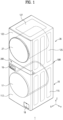
FIG. 1 is a perspective view of a laundry treating apparatus of an embodiment of the disclosure. -
FIG. 2 is a perspective view of a laundry treating apparatus of an embodiment of the disclosure. -
FIG. 3 is a perspective view of a laundry treating apparatus of an embodiment of the disclosure. -
FIG. 4 is a side view of laundry treating apparatus viewed from a rear side, of an embodiment of the present disclosure and is an enlarged diagram of portion A in which a rear bracket is located. -
FIG. 5 is a side view of laundry treating apparatus viewed from a rear side, of an embodiment of the present disclosure and is an enlarged diagram of a rear bracket in a disassembled state. -
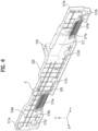
FIG. 6 is a front perspective view (a perspective view showing the inside) of a rear bracket according to an embodiment of the present disclosure. -
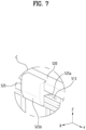
FIG. 7 is an enlarged view of a portion C ofFIG. 6 . -
FIG. 8 is an enlarged view of a portion B ofFIG. 5 . -
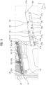
FIG. 9 is an enlarged perspective view of a portion D ofFIG. 4 , showing an enlarged portion at which a coupling protrusion is coupled to a coupling hole of a base. -
FIG. 10 is an enlarged perspective view of a portion E ofFIG. 4 and shows a portion in which a rear bracket is coupled to a first treating device and a second treating device, according to an embodiment of the present disclosure. -
FIG. 11 is an enlarged perspective view of a hose accommodation portion in a rear bracket of an embodiment of the present disclosure and shows the configuration of a second treating device. -
FIG. 12 is a diagram for explaining an example of use of a cap fixing rib of a rear bracket according to an embodiment of the present disclosure. -
FIG. 13 is a diagram of a rear bracket viewed from a rear side according to an embodiment of the present disclosure and shows a left side in which a right side is not shown. -
FIG. 14 is a diagram for explaining an example of use of a hose fixing portion of a rear bracket according to an embodiment of the present disclosure and shows a lower side of a laundry treating apparatus viewed from a rear side from which an upper side is omitted. - Embodiments of the present disclosure are described in detail so as for those of ordinary skill in the art to easily implement with reference to the accompanying drawings.
- However, the present disclosure may be implemented in various different forms and is not limited to these embodiments. To clearly describe the present disclosure, a part without concerning to the description is omitted in the drawings, and like reference numerals in the specification denote like elements.
- In the present specification, a repeated explanation of the same elements will not be given.
- It will be understood that when an element is referred to as being "connected to" or "coupled to" another element, it may be directly on, connected or coupled to the other element or intervening elements may be present. In contrast, when an element is referred to as being "directly connected to" or "directly coupled to" another element or layer, there are no intervening elements or layers present.
- The terms used in the present specification are used for explaining a specific embodiment, not limiting the present disclosure.
- In the present specification, the singular expressions include the plural expressions unless clearly specified otherwise in context.
- It will be further understood that the terms "comprises" and/or "comprising" when used in this specification, specify the presence of stated features, integers, steps, operations, elements, components, or combinations thereof but do not preclude the presence or addition of one or more other features, integers, steps, operations, elements, components, and/or combinations thereof.
- In the present specification, the term 'and/or' includes a combination of multiple listed items or any item of multiple listed items. In the present specification, 'a or b' may include 'a', 'b', or 'both a and b'.
-
FIG. 1 shows alaundry treating apparatus 1 according to an embodiment of the present disclosure.FIG. 2 is a perspective view of a laundry treating apparatus according to an embodiment of the present disclosure.FIG. 3 is a perspective view of a laundry treating apparatus according to an embodiment of the present disclosure. Referring toFIGS. 1 ,2 , and3 , the laundry treating apparatus according to an embodiment of the present disclosure is described. - In a description of the present disclosure, respective definitions of a front direction +X, a rear direction -X, a first lateral direction +Y, a second lateral direction -Y, and an upward direction +Z, a downward direction -Z for components may be defined with the same term. For example, the front and rear directions +X and -X of a first treating
device 10 may be defined in the same way as front and rear directions of acontrol panel 200 or the like, and the lateral directions +Y and -Y and the upward and downward directions +Z and -Z may be defined in the same way. - According to an embodiment of the present disclosure, the
laundry treating apparatus 1 includes a first treatingdevice 10, a second treatingdevice 20, acontrol panel 200, and arear bracket 500. - The first treating
device 10 and the second treatingdevice 20 may be provided as various types of devices for treating laundry, such as a washing machine for washing laundry and/or a dryer for drying laundry. The first treatingdevice 10 may be a washing machine and the second treatingdevice 20 may be a dryer. The first treatingdevice 10 and the second treatingdevice 20 may both be washing machines or dryers, or the first treatingdevice 10 may be a dryer and the second treatingdevice 20 may be a washing machine or may be various other devices for treating laundry. - According to an embodiment, the first treating
device 10 located at a lower side may correspond to a washing machine for washing laundry. Afirst drum 12 and atub 14 for accommodating laundry may be provided inside the first treatingdevice 10. Thefirst drum 12 inside the first treatingdevice 10 may be provided rotatably inside thetub 14. The second treatingdevice 20 is located above the first treatingdevice 10. The first treatingdevice 10 supports the second treatingdevice 20. The second treatingdevice 20 may correspond to a dryer for drying laundry. Thefirst drum 12 and thetub 14 for accommodating laundry may be provided inside the second treatingdevice 20. - The first treating
device 10 may include a first cabinet 110 defining an outer appearance. The first cabinet 110 may be provided with a firstfront panel 112 on a front side. A laundry opening communicating with thefirst drum 12 may be formed in the firstfront panel 112. The laundry opening may be opened and closed by afirst cabinet door 17. Thefirst drum 12 of the first treatingdevice 10 according to an embodiment has a rotation axis parallel to the front and rear directions +X and -X. - The first treating
device 10 may be provided with a firstlateral panel 115 on each side in the lateral direction Y, a firstrear panel 118 may be provided at a rear side, a first upper panel (not shown) may be provided at an upper side, and a first lower panel (not shown) may be provided at a lower side. - The first
front panel 112, the firstlateral panel 115, a first rear panel (not shown), a first upper panel (not shown), and a first lower panel (not shown) may be combined with each other to form the first cabinet 110 and may have a connecting relationship with each other. The first cabinet 110 may define a space in which internal components constituting the first cabinet 110, such as thefirst drum 12, are provided. - Laundry required to be treated is input into the first cabinet 110 through the laundry opening of the first treating
device 10. The input laundry may be accommodated inside thefirst drum 12 and treated by the first treatingdevice 10. - A detergent opening is formed in the first
front panel 112. Adetergent storage unit 16 is inserted and provided in the detergent opening. In thelaundry treating apparatus 1 according to an embodiment, the first treatingdevice 10 may be located on the ground, and thedetergent storage unit 16 may be located above the laundry opening of the first treatingdevice 10 to facilitate retraction and extension of thedetergent storage unit 16. Thedetergent storage unit 16 may be located between the laundry opening of the first treatingdevice 10 and thecontrol panel 200. That is, thedetergent storage unit 16 may be located above the laundry opening of the first treatingdevice 10 and below thecontrol panel 200. Thedetergent storage unit 16 may be retracted or extended into and out of the first cabinet 110 by a user. For example, the user may separate thedetergent storage unit 16 from the first cabinet 110, store detergent in thedetergent storage unit 16, and then retract thedetergent storage unit 16 into the first cabinet 110. - According to an embodiment, a filter opening is formed in the first
front panel 112. Afilter unit 18 is provided inserted into the filter opening. Thefilter unit 18 captures foreign substances from washing water. Thefilter unit 18 may be provided at one side of a lower portion of the firstfront panel 112. Thefilter unit 18 may be retracted into the first cabinet 110 through the filter opening and connected to a path of the washing water discharged from thetub 14. Thefilter unit 18 may filter out foreign substances from the washing water discharged from thetub 14 after a washing process is performed. A function of thefilter unit 18 is not necessarily limited thereto, and thefilter unit 18 may be provided to filter foreign substances from various objects as needed. For example, thefilter unit 18 may be provided to filter out foreign substances from the washing water used for performing the washing process before the washing process begins. - The user may retract or extend the
filter unit 18 into or out of the first cabinet 110 through the filter opening. Theextended filter unit 18 may be reused or replaced after being washed. Thefilter unit 18 may have a relatively long retract and extension cycle with respect to thedetergent storage unit 16, and accordingly, according to an embodiment of the present disclosure, the detergent opening into which thedetergent storage unit 16 with a relatively short retract and extension cycle is retracted may be located above the firstfront panel 112. The filter opening into which thefilter unit 18 with a relatively long retract and extension cycle is retracted may be located below the firstfront panel 112, thereby implementing a structure of the firstfront panel 112 with improved convenience of use and excellent space utilization. - A washing water discharge path connected to the
tub 14 inside the first cabinet 110 may be located at a lower side within the first cabinet 110 to facilitate discharge of washing water, and according to an embodiment of the present disclosure, thefilter unit 18 may be provided at the lower side of the first cabinet 110 and may be efficiently connected to the washing water discharge path. - A first device controller (not shown) may be provided in the first treating
device 10. The first device controller (not shown) is a component that controls various devices constituting the first treatingdevice 10. The first device controller (not shown) is located inside the first cabinet 110. The first device controller (not shown) may include a circuit board and electrical components mounted on the circuit board. According to an embodiment, the first device controller (not shown) may check information corresponding to an operation signal received from thecontrol panel 200 in a memory and perform device control corresponding to the operation signal. The first device controller (not shown) may transmit a state of the first treatingdevice 10 to thecontrol panel 200. - The second treating
device 20 may include a second cabinet 120 defining an outer appearance. The second cabinet 120 may include a secondfront panel 122 provided at a front side. A laundry opening communicating with asecond drum 22 may be formed in the secondfront panel 122. The laundry opening may be opened and closed by asecond cabinet door 27. - A second
lateral panel 125 may be provided on each of the lateral directions +Y and -Y of the second treatingdevice 20. A secondrear panel 128 may be provided at a rear side of the second treatingdevice 20. A secondupper panel 127 may be provided at an upper side of the second treatingdevice 20. A base 300 (seeFIG. 5 ) may be provided at a lower side of the second treatingdevice 20. - The second
front panel 122, the secondlateral panel 125, the secondrear panel 128, the secondupper panel 127, and the base 300 may be combined with each other to form the second cabinet 120 and may have a coupling relationship with each other. The second cabinet 120 may define a space in which internal components constituting the second treatingdevice 20, such as thesecond drum 22, are provided. - Laundry required to be treated may be input into the second cabinet 120 through the laundry opening of the second treating
device 20 and accommodated in thesecond drum 22. A treating process such as washing and drying by the second treatingdevice 20 may be performed on the laundry accommodated in thesecond drum 22. - The second treating
device 20 according to an embodiment may be provided with the laundry opening provided above the secondfront panel 122 together with thesecond cabinet door 27. Thesecond drum 22 accommodated in the second treatingdevice 20 has a rotation axis parallel to the front and rear directions X. - The second treating
device 20 is located above the first treatingdevice 10. According to an embodiment, the lower side of the first treatingdevice 10 may be coupled to the upper side of the second treatingdevice 20. The upper side of the first treatingdevice 10 may have a structure that supports the second treatingdevice 20. For example, the first upper panel (not shown) of the first treatingdevice 10 may have a structure that directly or indirectly supports thebase 300 of the second treatingdevice 20. - A second device controller (not shown) may be provided in the second treating
device 20. The second device controller (not shown) is a component that controls various devices constituting the second treatingdevice 20. The second device controller (not shown) is located inside the second cabinet 120. The second device controller (not shown) may include a circuit board and electrical components mounted on the circuit board. According to an embodiment, a second device controller 29 may check information corresponding to an operation signal received from thecontrol panel 200 in a memory and perform device control corresponding to the operation signal. The second device controller (not shown) may transmit a state of the second treatingdevice 20 to thecontrol panel 200. - The
control panel 200 is located between the firstfront panel 112 and the secondfront panel 122. Thecontrol panel 200 may be provided between the firstfront panel 112 and the secondfront panel 122 at a height that corresponds approximately to the waist of the user, thereby ensuring a height that is convenient for the user to operate. Thecontrol panel 200 may be signal-connected to at least one of the first treatingdevice 10 and the second treatingdevice 20. According to an embodiment, thecontrol panel 200 is signal-connected to the first treatingdevice 10 and the second treatingdevice 20. According to an embodiment, thecontrol panel 200 is signal-connected to the first device controller (not shown) and/or the second device controller (not shown). A user interface (UI) is displayed on a front surface of thecontrol panel 200. A user may control the first treatingdevice 10 and/or the second treatingdevice 20 through thecontrol panel 200. - The
rear bracket 500 is provided at a rear side of thelaundry treating apparatus 1. Therear bracket 500 is coupled to the first treatingdevice 10 and the second treatingdevice 20. Therear bracket 500 is located at an upper portion of the rear side of the first treatingdevice 10 and at a lower portion of the rear side of the second treatingdevice 20. -
FIG. 4 is a side view of laundry treating apparatus viewed from a rear side, according to an embodiment of the present disclosure and is an enlarged diagram of portion A in which a rear bracket is located. - The
rear bracket 500 is fixedly coupled to the first treatingdevice 10 and the second treatingdevice 20. Therear bracket 500 is coupled to the firstrear panel 118 and the secondrear panel 128. Therear bracket 500 is coupled to an upper portion of the firstrear panel 118 and a lower portion of the secondrear panel 128. - The
rear bracket 500 includes aface plate 510 and aperiphery portion 520. Theface plate 510 defines a rear surface of therear bracket 500. Theperiphery portion 520 protrudes forward from a periphery of theface plate 510. -
Handles rear bracket 500. Thehandles face plate 510. Thehandles face plate 510. A space is formed in thehandles handles handles first handle 515a and asecond handle 515b. Thefirst handle 515a may be provided at one side of therear bracket 500, and thesecond handle 515b may be provided on the other side of therear bracket 500. Considering that transportation of thelaundry treating apparatus 1 is mainly performed by two carriers, thehandles - A
coupling protrusion 525 is formed on therear bracket 500. Thecoupling protrusion 525 is provided as an example of a second guide in the present disclosure. Thecoupling protrusion 525 may be formed at an upper side of therear bracket 500. Thecoupling protrusion 525 may be formed to protrude further forward from theperiphery portion 520. Thecoupling protrusion 525 is inserted into a coupling hole 311 (seeFIG. 5 ) formed in anupper surface 310 of the base 300 (seeFIG. 5 ) of the second treatingdevice 20 described later. Thecoupling protrusion 525 is described in more detail with reference toFIGS. 6 and7 . - A
first opening 513 may be formed in a portion corresponding to thecoupling protrusion 525. - A
hose accommodation portion 517 is formed on therear bracket 500. Thehose accommodation portion 517 is formed by forming a convex surface rearward from therear bracket 500. Thehose accommodation portion 517 is formed at a portion corresponding to a drain hose of the second treatingdevice 20. - A
port opening 517a is formed on therear bracket 500. Theport opening 517a is formed at one side of thehose accommodation portion 517. Theport opening 517a is an opening formed such that a drain hose port 331 (seeFIG. 11 ) for discharging condensate is exposed to the outside. Theport opening 517a is formed at a position corresponding to thedrain hose port 331. - A
cap fixing rib 518 may be formed on therear bracket 500. Thecap fixing rib 518 includes afirst rib 518a and asecond rib 518b. Thefirst rib 518a protrudes upward. Thefirst rib 518a may be located above thehose accommodation portion 517. Thesecond rib 518b protrudes upward at a predetermined distance from thefirst rib 518a. Thecap fixing rib 518 is described in more detail with reference toFIG. 12 . - The
rear bracket 500 may further includehose fixing portions hose fixing portions FIG. 14 ). Thehose fixing portions drain hose port 331. Thehose fixing portions hose fixing portion 519a and a secondhose fixing portion 519b. According to an embodiment, thehose fixing portions hose fixing portion 519a and the secondhose fixing portion 519b. The firsthose fixing portion 519a is located inclined to one side with respect to thedrain hose port 331. The secondhose fixing portion 519b is formed on the other side with respect to thedrain hose port 331. That is, the secondhose fixing portion 519b may be located at an opposite side to a side at which the firsthose fixing portion 519a is located with respect to thedrain hose port 331. - The
hose fixing portions face plate 510. Thehose fixing portions FIG. 14 . -
FIG. 5 is a side view of laundry treating apparatus viewed from a rear side, according to an embodiment of the present disclosure and is an enlarged diagram of a rear bracket in a disassembled state. Referring toFIG. 5 , a coupling relationship of the first treatingdevice 10 and the second treatingdevice 20 with respect to therear bracket 500 is described. - The second treating
device 20 includes the base 300 defining an outer appearance of a lower portion. Although not shown, a circulation path in which a heat exchanger for removing moisture from air flowing in from thesecond drum 22, a water collector storing condensed moisture, and the like may be formed in thebase 300. -
FIG. 5 illustrates a portion of the base 300 exposed to a rear side of the second treatingdevice 20. Acoupling hole 311 is formed in theupper surface 310 of thebase 300. Thecoupling hole 311 is provided as an example of a first guide in the present disclosure. Thecoupling protrusion 525 is inserted into thecoupling hole 311 and connected thereto. An upper surface of thebase 300 is partially exposed. Thecoupling hole 311 is formed on the exposed portion of theupper surface 310 defining the upper surface of thebase 300. Thecoupling protrusion 525 of therear bracket 500 is inserted into thecoupling hole 311. By thecoupling protrusion 525 into thecoupling hole 311, therear bracket 500 may be temporarily coupled to thelaundry treating apparatus 1. The illustrated embodiment presents thecoupling hole 311 as an example of the first guide and thecoupling protrusion 525 as an example of the second guide. However, the first guide and the second guide are not limited thereto. In an example that is not shown, the first guide may be formed with a first protrusion protruding upward, the second guide portion may be formed with a second protrusion protruding downward, and the first guide and the second guide may be connected to each other by engagement of the first protrusion and the second protrusion. In another example that is not shown, the first guide may be formed with a coupling protrusion, the second guide may be formed with a coupling hole, and the first guide may be inserted into the second guide to connect the first guide and the second guide to each other. - Protruding
ribs base 300. The protrudingribs rear panel 128. The protrudingribs rear panel 128. The lower portion of the secondrear panel 128 may be restrained in position without being spread out of the base 300 by the protrudingribs ribs protruding rib 321b formed at the other side, and a thirdprotruding rib 321c formed at a central area. - The
drain hose port 331 is formed in the base 300 to discharge condensate to the outside of thelaundry treating apparatus 1. Thedrain hose port 331 may be connected to an water collector or condensate storage tank that is not shown. - First fixing
portions rear bracket 500.Second fixing portions rear bracket 500. Thefirst fixing portions rear bracket 500 and the first treatingdevice 10 are coupled to each other. Thesecond fixing portions rear bracket 500 and the second treatingdevice 20 are coupled to each other. Thefirst fixing portions second fixing portions first fixing portions second fixing portions first fixing portions second fixing portions laundry treating apparatus 1 from below using thehandles first fixing portions first fixing portions second fixing portions -
FIG. 6 is a front perspective view (a perspective view showing the inside) of a rear bracket according to an embodiment of the present disclosure. - A
vertical rib 510a and ahorizontal rib 510b for reinforcing strength may be formed inside therear bracket 500. Thevertical rib 510a and thehorizontal rib 510b may be formed inside theface plate 510. - The
first fixing portions second fixing portions - A curve may be formed inside the
handles - The
coupling protrusion 525 may be formed above thecoupling protrusion 525 and may protrude forward from theperiphery portion 520. -
FIG. 7 is an enlarged view of a portion C ofFIG. 6 . Referring toFIG. 7 , thecoupling protrusion 525 is described in more detail. - The
coupling protrusion 525 is formed in a hook shape. Thecoupling protrusion 525 includes aninsertion portion 525b extending downward. Theinsertion portion 525b is inserted into thecoupling hole 311. Theinsertion portion 525b may be inserted into thecoupling hole 311, and thus thelaundry treating apparatus 1 and therear bracket 500 may be temporarily coupled to each other without being fixed by thefirst fixing portions second fixing portions device 10 and a front-to-rear depth of the second treatingdevice 20 are almost the same. Accordingly, to fix therear bracket 500 to thelaundry treating apparatus 1 without a coupling relationship of thecoupling protrusion 525 to thecoupling hole 311, an additional operator may be required or more operating time may be required for either of thefirst fixing portions second fixing portions laundry treating apparatus 1, but according to an embodiment of the present disclosure, therear bracket 500 may be easily coupled to thelaundry treating apparatus 1 even if the front-to-rear depth of the first treatingdevice 10 and the front-to-rear depth of the second treatingdevice 20 are almost the same. - The
first opening 513 is formed in an area that overlaps thecoupling protrusion 525 when viewed from the front. An operator may more easily couple thecoupling protrusion 525 to thecoupling hole 311 by using thefirst opening 513. - A reinforcing
rib 525a protruding inwardly from thefirst opening 513 and extending toward thecoupling protrusion 525 may be further formed on therear bracket 500. The reinforcingrib 525a may protrude from an upper surface of thefirst opening 513 toward a lower surface. The reinforcingrib 525a may be formed in plural (seeFIG. 9 ). -
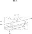
FIG. 8 is an enlarged view of a portion B ofFIG. 5 . - A portion of the upper surface of the
base 300 of the second treatingdevice 20 may be exposed to the outside. Thecoupling hole 311 is formed on the exposedupper surface 310. Thecoupling hole 311 may be formed to pass through theupper surface 310 in the upward and downward directions. When the thickness of theupper surface 310 is large, a groove may be formed rather than thecoupling hole 311. - The base 300 may include a plurality of
support ribs 315 that support theupper surface 310. The plurality ofsupport ribs 315 may reinforce the rigidity of thebase 300. -
FIG. 9 is an enlarged perspective view of a portion D ofFIG. 4 , showing an enlarged portion at which thecoupling protrusion 525 is coupled to a coupling hole of thebase 300. - A portion of the base 300 may be exposed through the
first opening 513. The reinforcingrib 525a protrudes from an upper surface of thefirst opening 513 toward a lower surface. The reinforcingrib 525a may extend to thecoupling protrusion 525 and may be integrated with thecoupling protrusion 525. In the illustrated embodiment, the reinforcingrib 525a is formed at three locations. -
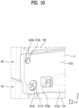
FIG. 10 is an enlarged perspective view of a portion E ofFIG. 4 and shows a portion in which a rear bracket is coupled to a first treating device and a second treating device, according to an embodiment of the present disclosure. - A
first fixing portion 511b of therear bracket 500 provides an accommodation surface into which afirst fastening member 541b is to be penetrated and coupled. Asecond fixing portion 512b of therear bracket 500 provides an accommodation surface into which asecond fastening member 542b is to be penetrated and connected. - The
rear bracket 500 is combined with the firstrear panel 118 of the first treatingdevice 10 by thefirst fastening member 541b. Therear bracket 500 is coupled to the secondrear panel 128 of the second treatingdevice 20 by thesecond fastening member 542b. Therear bracket 500 is coupled to the first treatingdevice 10 and the second treatingdevice 20. -
FIG. 11 is an enlarged perspective view of a hose accommodation portion in a rear bracket according to an embodiment of the present disclosure and shows the configuration of a second treating device. - The
drain hose port 331 coupled to asecond drain hose 25 is formed in thebase 300 of the second treatingdevice 20. Thedrain hose port 331 is configured to discharge condensate to the outside of thelaundry treating apparatus 1. A flow path of thedrain hose port 331 may be connected to a connecting hose (not shown) connecting a first connectingport 332 and a second connectingport 333 to each other. A portion of the connecting hose (not shown) connecting the first connectingport 332 and the second connectingport 333 to each other may be located further rearward than a general surface of theface plate 510 of therear bracket 500. Thehose accommodation portion 517 is formed in therear bracket 500 to accommodate the connecting hose (not shown). Thehose accommodation portion 517 is formed by forming a convex surface rearward from therear bracket 500. - The
port opening 517a is an opening formed such that thedrain hose port 331 is exposed to the outside. Theport opening 517a is formed at a position corresponding to thedrain hose port 331. -
FIG. 12 is a diagram for explaining an example of use of thecap fixing rib 518 of a rear bracket according to an embodiment of the present disclosure. - The
cap fixing rib 518 includes thefirst rib 518a and thesecond rib 518b. Thefirst rib 518a protrudes upward. Thefirst rib 518a may be located above thehose accommodation portion 517. Thesecond rib 518b protrudes upward at a predetermined distance from thefirst rib 518a. - A
test port 338 is located between thefirst rib 518a and thesecond rib 518b. Thetest port 338 is used for product inspection and is not used for users after being shipped. Thetest port 338 may be closed using acap 339. Thecap 339 that closes thetest port 338 has a problem of being lost during transport or installation. Thecap fixing rib 518 is configured to rub against thecap 339 on both sides to support thecap 339 to be prevented from coming off from thetest port 338. A gap between thefirst rib 518a and thesecond rib 518b is sufficient to cause friction with thecap 339. -
FIG. 13 is a diagram of a rear bracket viewed from a rear side according to an embodiment of the present disclosure and shows a left side in which a right side is not shown. - The
hose fixing portions rear bracket 500. Thehose fixing portions hose fixing portion 519a and a secondhose fixing portion 519b. According to an embodiment, thehose fixing portions hose fixing portion 519a and the secondhose fixing portion 519b. The firsthose fixing portion 519a is located inclined to one side with respect to thedrain hose port 331. The secondhose fixing portion 519b is formed on the other side with respect to thedrain hose port 331. That is, the secondhose fixing portion 519b may be located at an opposite side to a side at which the firsthose fixing portion 519a is located with respect to thedrain hose port 331. - The
hose fixing portions drain hose port 331 is located. According to an embodiment, the firsthose fixing portion 519a is formed at a first height H1 lower than the location at which thedrain hose port 331 is located. According to an embodiment, the secondhose fixing portion 519b is formed at a second height H2 lower than the location at which thedrain hose port 331 is located. According to an embodiment, the first height H1 and the second height H2 may be equal to each other. - The
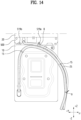
hose fixing portions FIG. 14 ). Further explanation is provided with reference toFIG. 14. FIG. 14 is a diagram for explaining an example of use of a hose fixing portion of a rear bracket according to an embodiment of the present disclosure and shows a lower side of a laundry treating apparatus viewed from a rear side from which an upper side is omitted. - The
laundry treating apparatus 1 is provided with afirst drain hose 15 and asecond drain hose 25 and the present disclosure is to simply organizing thefirst drain hose 15 and thesecond drain hose 25. According to an embodiment of the present disclosure, thefirst drain hose 15 and thesecond drain hose 25 may be simply organized by fixing the location of the second drain hose 28 by using thehose fixing portions first drain hose 15 to each other. - According to an embodiment, the first treating
device 10 is provided as a washing machine. Thefirst drain hose 15 for draining washing water used in the first treatingdevice 10 is provided using a flexible material. Thefirst drain hose 15 includes more flexible material than thesecond drain hose 25. A portion of thefirst drain hose 15 may need to be located above the first treatingdevice 10. That is, thefirst drain hose 15 may be fixed to start from below thefirst drum 12 in the first treatingdevice 10, extend above the first drum 12 (seeFIG. 2 ), and then be located again toward an external drain. - The
hose fixing portions first drain hose 15 at a desired location according to an installation environment through a coupling relationship with the second drain hose 28. Depending on the installation environment, the desired location may be where the drain is located. According to an embodiment of the present disclosure, thefirst drain hose 15 may be effectively and economically fixed in position by using thehose fixing portions - The
hose fixing portions hose fixing portion 519a is used is described, as the installation environment has a drain located in the +Y direction. If the installation environment has the drain located in the -Y direction, the secondhose fixing portion 519b may be used. - The first
hose fixing portion 519a fixes thesecond drain hose 25 in the +Y direction. According to an embodiment, Thesecond drain hose 25 is fixed to the firsthose fixing portion 519a. For example, thesecond drain hose 25 is fixed to the firsthose fixing portion 519a by a string, a tie, or the like. - The
first drain hose 15 may include a fixing portion 15a that fixes thefirst drain hose 15 upward to position a portion of thefirst drain hose 15 upward. In general, thefirst drain hose 15 may be fixed upward, but may not be fixed in the +Y direction or the -Y direction. This is because the location of the drain varies depending on the installation environment. Thefirst drain hose 15 is relatively flexible and thus is difficult to fix a location thereof to the drain port. On the other hand, the second drain hose 28 is relatively less likely to bend compared to thefirst drain hose 15. according to an embodiment of the present disclosure, the second drain hose 28 may be fixed in position by the firsthose fixing portion 519a, and thefirst drain hose 15 may be coupled to the second drain hose 28, thereby fixing thefirst drain hose 15 in position in a direction of the drain port. Thefirst drain hose 15 and the second drain hose 28 may be bound to each other by a binding member 9. The binding member 9 may be a string or a cable tie. The binding location of thefirst drain hose 15 and the second drain hose 28 may be downstream from the location at which thefirst drain hose 15 and the second drain hose 28 are fixed. - While the present disclosure has been illustrated and described with respect to specific embodiments thereof, it will be apparent to those of skill in the art that the present disclosure may be variously improved and modified without departing from the technical spirit of the disclosure as defined by the following claims.
Claims (18)
- A laundry treating apparatus comprising:a first treating device including a first cabinet including a first rear panel defining a rear surface and a first drum provided inside the first cabinet and configured to accommodate laundry;a second treating device including a second cabinet positioned above the first treating device and including a second rear panel defining a rear surface and a second drum provided inside the first cabinet and configured to accommodate laundry; anda rear bracket coupled to the first rear panel and the second rear panel and having a handle formed therein to define a space for accommodating a hand of a carrier,wherein the second treating device includes a first guide formed thereon for coupling with the rear bracket and includes a second guide formed at a location of the rear bracket, which corresponds to the first guide, and connected to the first guide.
- The laundry treating apparatus of claim 1, wherein the first guide is formed as a coupling hole,the second guide is formed as a coupling protrusion protruding toward the second rear panel, andthe coupling protrusion is configured to be inserted into the coupling hole.
- The laundry treating apparatus of claim 2, wherein the coupling protrusion includes an insertion portion extending downward, and the insertion portion is inserted into the coupling hole.
- The laundry treating apparatus of claim 1, wherein the second treating device further includes a base forming the lower exterior of the second treating device, and the second guide is located on the base.
- The laundry treating apparatus of claim 4, wherein the first guide is formed on an upper surface of the base.
- The laundry treating apparatus of any one of claims 1 to 5, wherein the rear bracket includes a first fixing portion coupled to the first treating device through a fastening member and a second fixing portion coupled to the second treating device through a fastening member.
- The laundry treating apparatus of claim 2, wherein a first opening is formed in an area of the rear bracket, which is located behind the coupling protrusion, and
the rear bracket further includes a plurality of reinforcing ribs that protrude inwardly of the first opening and extend to the coupling protrusion. - The laundry treating apparatus of claim 7, wherein the plurality of reinforcing ribs protrude downward from an upper surface of the first opening and extend to the coupling protrusion.
- The laundry treating apparatus of claim 4, wherein a protruding rib protruding upward is formed at a rear end of the base, and
the protruding rib is located behind the second rear panel and restrains a location of a lower portion of the second rear panel. - The laundry treating apparatus of claim 1, wherein the second treating device further includes a drain hose port configured to discharge water inside the second cabinet, and a second drain hose coupled to the drain hose port, and
a port opening is formed at a location of the rear bracket, which corresponds to the drain hose port, such that the drain hose port is exposed to an outside. - The laundry treating apparatus of claim 10, wherein the rear bracket includes at least one of a first hose fixing portion located lower than the drain hose port and spaced to one side from the drain hose port to fix the second drain hose, and a second hose fixing portion located lower than the drain hose port and spaced to another side from the drain hose port to fix the second drain hose.
- The laundry treating apparatus of claim 11, wherein the first treating device further includes a first drain hose configured to drain water inside the first cabinet, and
the second drain hose is bound to the first drain hose at a downstream side from a portion fixed by at least one of the first hose fixing portion and the second hose fixing portion. - The laundry treating apparatus of claim 12, wherein the first drain hose is configured to extend from below the first drum of the first treating device to above the first drum.
- A laundry treating apparatus comprising:a first treating device including a first cabinet including a first rear panel defining a rear surface and a first drum configured to accommodate laundry therein;a second treating device including a second cabinet that is disposed above the first treating device and defines a rear surface, a second drum configured to accommodate laundry therein, a drain hose port provided in the second rear panel to discharge water, and a second drain hose coupled to the drain hose port; anda rear bracket coupled to the first rear panel and the second rear panel and having a handle formed therein to provide a space for accommodating a hand of a carrier,wherein the rear bracket includes a first hose fixing portion that is spaced to one side from the drain hose port and fixes the second drain hose.
- The laundry treating apparatus of claim 14, wherein the first hose fixing portion is located lower than the drain hose port.
- The laundry treating apparatus of claim 14, wherein a location of the second drain hose is restricted by the first hose fixing portion,the first treating device further includes a first drain hose configured to drain water inside the first cabinet, andthe second drain hose is bound to the first drain hose at a downstream side from the first hose fixing portion.
- The laundry treating apparatus of claim 14, further comprising a second hose fixing portion that is spaced to another side from the drain hose port and fixes the second drain hose,wherein the second drain hose is fixed by either the first hose fixing portion or the second hose fixing portion,the first treating device further includes a first drain hose configured to drain water inside the first cabinet, andthe second drain hose is bound to the first drain hose at a downstream side from a portion fixed by either the first hose fixing portion or the second hose fixing portion.
- The laundry treating apparatus of claim 17, wherein the first drain hose is configured to extend from below the first drum of the first treating device to above the first drum.
Applications Claiming Priority (2)
| Application Number | Priority Date | Filing Date | Title |
|---|---|---|---|
| KR1020220073529A KR102805591B1 (en) | 2022-06-16 | 2022-06-16 | Apparatus for treating laundry |
| PCT/KR2023/008305 WO2023244041A1 (en) | 2022-06-16 | 2023-06-15 | Apparatus for treating laundry |
Publications (2)
| Publication Number | Publication Date |
|---|---|
| EP4534750A1 true EP4534750A1 (en) | 2025-04-09 |
| EP4534750A4 EP4534750A4 (en) | 2025-10-15 |
Family
ID=89191653
Family Applications (1)
| Application Number | Title | Priority Date | Filing Date |
|---|---|---|---|
| EP23824254.9A Pending EP4534750A4 (en) | 2022-06-16 | 2023-06-15 | LAUNDRY TREATMENT APPARATUS |
Country Status (6)
| Country | Link |
|---|---|
| US (1) | US20250361664A1 (en) |
| EP (1) | EP4534750A4 (en) |
| KR (2) | KR102805591B1 (en) |
| CN (1) | CN119384534A (en) |
| AU (1) | AU2023292779B2 (en) |
| WO (1) | WO2023244041A1 (en) |
Family Cites Families (9)
| Publication number | Priority date | Publication date | Assignee | Title |
|---|---|---|---|---|
| US4680948A (en) * | 1985-01-10 | 1987-07-21 | White Consolidated Industries, Inc. | Dryer mounting bracket assembly |
| KR20060005849A (en) * | 2004-07-14 | 2006-01-18 | 삼성전자주식회사 | Home appliances with vertical fastening structure and fastening method |
| KR20100001438A (en) * | 2008-06-27 | 2010-01-06 | 주식회사 대우일렉트로닉스 | Bracket for heaping home appliances |
| KR20120056712A (en) * | 2010-11-25 | 2012-06-04 | 주식회사 대우일렉트로닉스 | Assembling device of handle for washing machine |
| WO2013038004A1 (en) * | 2011-09-16 | 2013-03-21 | Arcelik Anonim Sirketi | A washer |
| KR20180105370A (en) * | 2017-03-15 | 2018-09-28 | 엘지전자 주식회사 | Laundry Treating Apparatus |
| KR102647029B1 (en) * | 2020-02-19 | 2024-03-14 | 엘지전자 주식회사 | Laundry treating apparatus |
| KR102505418B1 (en) * | 2020-02-21 | 2023-03-03 | 엘지전자 주식회사 | Laundry Treatment Apparatus and Control Method for the same |
| KR102550659B1 (en) * | 2020-03-04 | 2023-07-03 | 엘지전자 주식회사 | Laundry treating apparatus |
-
2022
- 2022-06-16 KR KR1020220073529A patent/KR102805591B1/en active Active
-
2023
- 2023-06-15 EP EP23824254.9A patent/EP4534750A4/en active Pending
- 2023-06-15 AU AU2023292779A patent/AU2023292779B2/en active Active
- 2023-06-15 WO PCT/KR2023/008305 patent/WO2023244041A1/en not_active Ceased
- 2023-06-15 CN CN202380047414.7A patent/CN119384534A/en active Pending
- 2023-06-15 US US18/874,530 patent/US20250361664A1/en active Pending
-
2025
- 2025-05-02 KR KR1020250058190A patent/KR102850380B1/en active Active
Also Published As
| Publication number | Publication date |
|---|---|
| KR102850380B1 (en) | 2025-08-27 |
| KR102805591B1 (en) | 2025-05-13 |
| AU2023292779B2 (en) | 2026-04-09 |
| AU2023292779A1 (en) | 2024-12-19 |
| EP4534750A4 (en) | 2025-10-15 |
| CN119384534A (en) | 2025-01-28 |
| US20250361664A1 (en) | 2025-11-27 |
| KR20250070008A (en) | 2025-05-20 |
| KR20230172848A (en) | 2023-12-26 |
| WO2023244041A1 (en) | 2023-12-21 |
Similar Documents
| Publication | Publication Date | Title |
|---|---|---|
| KR102550659B1 (en) | Laundry treating apparatus | |
| JP7676451B2 (en) | Clothes Processing Equipment | |
| KR20090057793A (en) | Clothing processing unit | |
| EP2065506B1 (en) | Laundry machine | |
| KR20230111181A (en) | Laundry treating apparatus | |
| EP4534750A1 (en) | Apparatus for treating laundry | |
| KR20250120957A (en) | Laundry treating apparatus | |
| KR102711599B1 (en) | Laundry treating apparatus | |
| KR102794801B1 (en) | Laundry treating apparatus | |
| KR102814548B1 (en) | Apparatus for treating laundry | |
| RU2793111C2 (en) | Device for washing and treatment of laundry | |
| KR102808506B1 (en) | Apparatus for treating laundry |
Legal Events
| Date | Code | Title | Description |
|---|---|---|---|
| STAA | Information on the status of an ep patent application or granted ep patent |
Free format text: STATUS: THE INTERNATIONAL PUBLICATION HAS BEEN MADE |
|
| PUAI | Public reference made under article 153(3) epc to a published international application that has entered the european phase |
Free format text: ORIGINAL CODE: 0009012 |
|
| STAA | Information on the status of an ep patent application or granted ep patent |
Free format text: STATUS: REQUEST FOR EXAMINATION WAS MADE |
|
| 17P | Request for examination filed |
Effective date: 20241231 |
|
| AK | Designated contracting states |
Kind code of ref document: A1 Designated state(s): AL AT BE BG CH CY CZ DE DK EE ES FI FR GB GR HR HU IE IS IT LI LT LU LV MC ME MK MT NL NO PL PT RO RS SE SI SK SM TR |
|
| REG | Reference to a national code |
Ref country code: DE Ref legal event code: R079 Free format text: PREVIOUS MAIN CLASS: D06F0039000000 Ipc: D06F0029000000 |
|
| DAV | Request for validation of the european patent (deleted) | ||
| DAX | Request for extension of the european patent (deleted) | ||
| A4 | Supplementary search report drawn up and despatched |
Effective date: 20250916 |
|
| RIC1 | Information provided on ipc code assigned before grant |
Ipc: D06F 29/00 20060101AFI20250910BHEP Ipc: D06F 31/00 20060101ALI20250910BHEP Ipc: D06F 39/08 20060101ALI20250910BHEP Ipc: D06F 58/20 20060101ALI20250910BHEP Ipc: D06F 39/00 20240101ALI20250910BHEP Ipc: D06F 39/12 20060101ALI20250910BHEP |