EP4534722A1 - Snout control system, and hot-dip galvanizing equipment comprising same - Google Patents
Snout control system, and hot-dip galvanizing equipment comprising same Download PDFInfo
- Publication number
- EP4534722A1 EP4534722A1 EP23816283.8A EP23816283A EP4534722A1 EP 4534722 A1 EP4534722 A1 EP 4534722A1 EP 23816283 A EP23816283 A EP 23816283A EP 4534722 A1 EP4534722 A1 EP 4534722A1
- Authority
- EP
- European Patent Office
- Prior art keywords
- snout
- dam
- dip galvanizing
- hot dip
- snorkel
- Prior art date
- Legal status (The legal status is an assumption and is not a legal conclusion. Google has not performed a legal analysis and makes no representation as to the accuracy of the status listed.)
- Pending
Links
Images




Classifications
-
- C—CHEMISTRY; METALLURGY
- C23—COATING METALLIC MATERIAL; COATING MATERIAL WITH METALLIC MATERIAL; CHEMICAL SURFACE TREATMENT; DIFFUSION TREATMENT OF METALLIC MATERIAL; COATING BY VACUUM EVAPORATION, BY SPUTTERING, BY ION IMPLANTATION OR BY CHEMICAL VAPOUR DEPOSITION, IN GENERAL; INHIBITING CORROSION OF METALLIC MATERIAL OR INCRUSTATION IN GENERAL
- C23C—COATING METALLIC MATERIAL; COATING MATERIAL WITH METALLIC MATERIAL; SURFACE TREATMENT OF METALLIC MATERIAL BY DIFFUSION INTO THE SURFACE, BY CHEMICAL CONVERSION OR SUBSTITUTION; COATING BY VACUUM EVAPORATION, BY SPUTTERING, BY ION IMPLANTATION OR BY CHEMICAL VAPOUR DEPOSITION, IN GENERAL
- C23C2/00—Hot-dipping or immersion processes for applying the coating material in the molten state without affecting the shape; Apparatus therefor
- C23C2/04—Hot-dipping or immersion processes for applying the coating material in the molten state without affecting the shape; Apparatus therefor characterised by the coating material
- C23C2/06—Zinc or cadmium or alloys based thereon
-
- C—CHEMISTRY; METALLURGY
- C23—COATING METALLIC MATERIAL; COATING MATERIAL WITH METALLIC MATERIAL; CHEMICAL SURFACE TREATMENT; DIFFUSION TREATMENT OF METALLIC MATERIAL; COATING BY VACUUM EVAPORATION, BY SPUTTERING, BY ION IMPLANTATION OR BY CHEMICAL VAPOUR DEPOSITION, IN GENERAL; INHIBITING CORROSION OF METALLIC MATERIAL OR INCRUSTATION IN GENERAL
- C23C—COATING METALLIC MATERIAL; COATING MATERIAL WITH METALLIC MATERIAL; SURFACE TREATMENT OF METALLIC MATERIAL BY DIFFUSION INTO THE SURFACE, BY CHEMICAL CONVERSION OR SUBSTITUTION; COATING BY VACUUM EVAPORATION, BY SPUTTERING, BY ION IMPLANTATION OR BY CHEMICAL VAPOUR DEPOSITION, IN GENERAL
- C23C2/00—Hot-dipping or immersion processes for applying the coating material in the molten state without affecting the shape; Apparatus therefor
- C23C2/50—Controlling or regulating the coating processes
- C23C2/52—Controlling or regulating the coating processes with means for measuring or sensing
- C23C2/523—Bath level or amount
-
- C—CHEMISTRY; METALLURGY
- C23—COATING METALLIC MATERIAL; COATING MATERIAL WITH METALLIC MATERIAL; CHEMICAL SURFACE TREATMENT; DIFFUSION TREATMENT OF METALLIC MATERIAL; COATING BY VACUUM EVAPORATION, BY SPUTTERING, BY ION IMPLANTATION OR BY CHEMICAL VAPOUR DEPOSITION, IN GENERAL; INHIBITING CORROSION OF METALLIC MATERIAL OR INCRUSTATION IN GENERAL
- C23C—COATING METALLIC MATERIAL; COATING MATERIAL WITH METALLIC MATERIAL; SURFACE TREATMENT OF METALLIC MATERIAL BY DIFFUSION INTO THE SURFACE, BY CHEMICAL CONVERSION OR SUBSTITUTION; COATING BY VACUUM EVAPORATION, BY SPUTTERING, BY ION IMPLANTATION OR BY CHEMICAL VAPOUR DEPOSITION, IN GENERAL
- C23C2/00—Hot-dipping or immersion processes for applying the coating material in the molten state without affecting the shape; Apparatus therefor
- C23C2/003—Apparatus
-
- C—CHEMISTRY; METALLURGY
- C23—COATING METALLIC MATERIAL; COATING MATERIAL WITH METALLIC MATERIAL; CHEMICAL SURFACE TREATMENT; DIFFUSION TREATMENT OF METALLIC MATERIAL; COATING BY VACUUM EVAPORATION, BY SPUTTERING, BY ION IMPLANTATION OR BY CHEMICAL VAPOUR DEPOSITION, IN GENERAL; INHIBITING CORROSION OF METALLIC MATERIAL OR INCRUSTATION IN GENERAL
- C23C—COATING METALLIC MATERIAL; COATING MATERIAL WITH METALLIC MATERIAL; SURFACE TREATMENT OF METALLIC MATERIAL BY DIFFUSION INTO THE SURFACE, BY CHEMICAL CONVERSION OR SUBSTITUTION; COATING BY VACUUM EVAPORATION, BY SPUTTERING, BY ION IMPLANTATION OR BY CHEMICAL VAPOUR DEPOSITION, IN GENERAL
- C23C2/00—Hot-dipping or immersion processes for applying the coating material in the molten state without affecting the shape; Apparatus therefor
- C23C2/003—Apparatus
- C23C2/0034—Details related to elements immersed in bath
- C23C2/00342—Moving elements, e.g. pumps or mixers
- C23C2/00344—Means for moving substrates, e.g. immersed rollers or immersed bearings
-
- C—CHEMISTRY; METALLURGY
- C23—COATING METALLIC MATERIAL; COATING MATERIAL WITH METALLIC MATERIAL; CHEMICAL SURFACE TREATMENT; DIFFUSION TREATMENT OF METALLIC MATERIAL; COATING BY VACUUM EVAPORATION, BY SPUTTERING, BY ION IMPLANTATION OR BY CHEMICAL VAPOUR DEPOSITION, IN GENERAL; INHIBITING CORROSION OF METALLIC MATERIAL OR INCRUSTATION IN GENERAL
- C23C—COATING METALLIC MATERIAL; COATING MATERIAL WITH METALLIC MATERIAL; SURFACE TREATMENT OF METALLIC MATERIAL BY DIFFUSION INTO THE SURFACE, BY CHEMICAL CONVERSION OR SUBSTITUTION; COATING BY VACUUM EVAPORATION, BY SPUTTERING, BY ION IMPLANTATION OR BY CHEMICAL VAPOUR DEPOSITION, IN GENERAL
- C23C2/00—Hot-dipping or immersion processes for applying the coating material in the molten state without affecting the shape; Apparatus therefor
- C23C2/003—Apparatus
- C23C2/0038—Apparatus characterised by the pre-treatment chambers located immediately upstream of the bath or occurring locally before the dipping process
- C23C2/004—Snouts
-
- C—CHEMISTRY; METALLURGY
- C23—COATING METALLIC MATERIAL; COATING MATERIAL WITH METALLIC MATERIAL; CHEMICAL SURFACE TREATMENT; DIFFUSION TREATMENT OF METALLIC MATERIAL; COATING BY VACUUM EVAPORATION, BY SPUTTERING, BY ION IMPLANTATION OR BY CHEMICAL VAPOUR DEPOSITION, IN GENERAL; INHIBITING CORROSION OF METALLIC MATERIAL OR INCRUSTATION IN GENERAL
- C23C—COATING METALLIC MATERIAL; COATING MATERIAL WITH METALLIC MATERIAL; SURFACE TREATMENT OF METALLIC MATERIAL BY DIFFUSION INTO THE SURFACE, BY CHEMICAL CONVERSION OR SUBSTITUTION; COATING BY VACUUM EVAPORATION, BY SPUTTERING, BY ION IMPLANTATION OR BY CHEMICAL VAPOUR DEPOSITION, IN GENERAL
- C23C2/00—Hot-dipping or immersion processes for applying the coating material in the molten state without affecting the shape; Apparatus therefor
- C23C2/325—Processes or devices for cleaning the bath
-
- C—CHEMISTRY; METALLURGY
- C23—COATING METALLIC MATERIAL; COATING MATERIAL WITH METALLIC MATERIAL; CHEMICAL SURFACE TREATMENT; DIFFUSION TREATMENT OF METALLIC MATERIAL; COATING BY VACUUM EVAPORATION, BY SPUTTERING, BY ION IMPLANTATION OR BY CHEMICAL VAPOUR DEPOSITION, IN GENERAL; INHIBITING CORROSION OF METALLIC MATERIAL OR INCRUSTATION IN GENERAL
- C23C—COATING METALLIC MATERIAL; COATING MATERIAL WITH METALLIC MATERIAL; SURFACE TREATMENT OF METALLIC MATERIAL BY DIFFUSION INTO THE SURFACE, BY CHEMICAL CONVERSION OR SUBSTITUTION; COATING BY VACUUM EVAPORATION, BY SPUTTERING, BY ION IMPLANTATION OR BY CHEMICAL VAPOUR DEPOSITION, IN GENERAL
- C23C2/00—Hot-dipping or immersion processes for applying the coating material in the molten state without affecting the shape; Apparatus therefor
- C23C2/34—Hot-dipping or immersion processes for applying the coating material in the molten state without affecting the shape; Apparatus therefor characterised by the shape of the material to be treated
- C23C2/36—Elongated material
- C23C2/40—Plates; Strips
-
- C—CHEMISTRY; METALLURGY
- C23—COATING METALLIC MATERIAL; COATING MATERIAL WITH METALLIC MATERIAL; CHEMICAL SURFACE TREATMENT; DIFFUSION TREATMENT OF METALLIC MATERIAL; COATING BY VACUUM EVAPORATION, BY SPUTTERING, BY ION IMPLANTATION OR BY CHEMICAL VAPOUR DEPOSITION, IN GENERAL; INHIBITING CORROSION OF METALLIC MATERIAL OR INCRUSTATION IN GENERAL
- C23C—COATING METALLIC MATERIAL; COATING MATERIAL WITH METALLIC MATERIAL; SURFACE TREATMENT OF METALLIC MATERIAL BY DIFFUSION INTO THE SURFACE, BY CHEMICAL CONVERSION OR SUBSTITUTION; COATING BY VACUUM EVAPORATION, BY SPUTTERING, BY ION IMPLANTATION OR BY CHEMICAL VAPOUR DEPOSITION, IN GENERAL
- C23C2/00—Hot-dipping or immersion processes for applying the coating material in the molten state without affecting the shape; Apparatus therefor
- C23C2/50—Controlling or regulating the coating processes
- C23C2/51—Computer-controlled implementation
-
- C—CHEMISTRY; METALLURGY
- C23—COATING METALLIC MATERIAL; COATING MATERIAL WITH METALLIC MATERIAL; CHEMICAL SURFACE TREATMENT; DIFFUSION TREATMENT OF METALLIC MATERIAL; COATING BY VACUUM EVAPORATION, BY SPUTTERING, BY ION IMPLANTATION OR BY CHEMICAL VAPOUR DEPOSITION, IN GENERAL; INHIBITING CORROSION OF METALLIC MATERIAL OR INCRUSTATION IN GENERAL
- C23C—COATING METALLIC MATERIAL; COATING MATERIAL WITH METALLIC MATERIAL; SURFACE TREATMENT OF METALLIC MATERIAL BY DIFFUSION INTO THE SURFACE, BY CHEMICAL CONVERSION OR SUBSTITUTION; COATING BY VACUUM EVAPORATION, BY SPUTTERING, BY ION IMPLANTATION OR BY CHEMICAL VAPOUR DEPOSITION, IN GENERAL
- C23C2/00—Hot-dipping or immersion processes for applying the coating material in the molten state without affecting the shape; Apparatus therefor
- C23C2/50—Controlling or regulating the coating processes
- C23C2/52—Controlling or regulating the coating processes with means for measuring or sensing
-
- C—CHEMISTRY; METALLURGY
- C23—COATING METALLIC MATERIAL; COATING MATERIAL WITH METALLIC MATERIAL; CHEMICAL SURFACE TREATMENT; DIFFUSION TREATMENT OF METALLIC MATERIAL; COATING BY VACUUM EVAPORATION, BY SPUTTERING, BY ION IMPLANTATION OR BY CHEMICAL VAPOUR DEPOSITION, IN GENERAL; INHIBITING CORROSION OF METALLIC MATERIAL OR INCRUSTATION IN GENERAL
- C23C—COATING METALLIC MATERIAL; COATING MATERIAL WITH METALLIC MATERIAL; SURFACE TREATMENT OF METALLIC MATERIAL BY DIFFUSION INTO THE SURFACE, BY CHEMICAL CONVERSION OR SUBSTITUTION; COATING BY VACUUM EVAPORATION, BY SPUTTERING, BY ION IMPLANTATION OR BY CHEMICAL VAPOUR DEPOSITION, IN GENERAL
- C23C2/00—Hot-dipping or immersion processes for applying the coating material in the molten state without affecting the shape; Apparatus therefor
- C23C2/14—Removing excess of molten coatings; Controlling or regulating the coating thickness
- C23C2/16—Removing excess of molten coatings; Controlling or regulating the coating thickness using fluids under pressure, e.g. air knives
- C23C2/18—Removing excess of molten coatings from elongated material
- C23C2/20—Strips; Plates
-
- C—CHEMISTRY; METALLURGY
- C23—COATING METALLIC MATERIAL; COATING MATERIAL WITH METALLIC MATERIAL; CHEMICAL SURFACE TREATMENT; DIFFUSION TREATMENT OF METALLIC MATERIAL; COATING BY VACUUM EVAPORATION, BY SPUTTERING, BY ION IMPLANTATION OR BY CHEMICAL VAPOUR DEPOSITION, IN GENERAL; INHIBITING CORROSION OF METALLIC MATERIAL OR INCRUSTATION IN GENERAL
- C23C—COATING METALLIC MATERIAL; COATING MATERIAL WITH METALLIC MATERIAL; SURFACE TREATMENT OF METALLIC MATERIAL BY DIFFUSION INTO THE SURFACE, BY CHEMICAL CONVERSION OR SUBSTITUTION; COATING BY VACUUM EVAPORATION, BY SPUTTERING, BY ION IMPLANTATION OR BY CHEMICAL VAPOUR DEPOSITION, IN GENERAL
- C23C2/00—Hot-dipping or immersion processes for applying the coating material in the molten state without affecting the shape; Apparatus therefor
- C23C2/26—After-treatment
Definitions
- the present disclosure relates to a snout control system and a hot dip galvanizing facility including the same, and more particularly, to a snout control system capable of automatically removing dross that floats within a snout apparatus during a process of producing a hot dip galvanizing steel plate and a hot dip galvanizing facility including the same.
- a hot dip galvanizing facility is a molten metal facility that plates zinc coating on a surface of a steel plate having a high temperature by dissolving a zinc ingot into a high temperature melting state having 450 degrees or higher.
- dross having an Fe2Al structure that is, an intermetallic compound, always occurs due to a temperature difference with ambient air and thermal and chemical instability, such as zinc oxidation attributable to a contact with discharging wiping air of an air knife that floats on a molten metal surface after colliding against a vertical strip surface.
- Such dross is adsorbed on a surface of the steel plate, and may cause various problems, such as a processing crack, plating peeling, the deterioration of coating properties, etc. during secondary processing.
- dross needs to be more strictly managed.
- a snout control system using a method of discharging dross that has crossed out to a dam to the back of a zinc plating bath, by using a structure having a dam form and a metal pump facility within the snorkel part of a snout apparatus in order to remove dross that floats within the snout apparatus.
- a snorkel part connected to the snout apparatus is integrally fabricated by being welded to the dam therein.
- the steel plate needs to be cut in order to replace the snorkel part, and thus there is a problem with productivity because a maintenance time for equipment is increased.
- an object of the present disclosure is to provide a snout control system and method, which enable work convenience and quality stability to be secured by automatically analyzing the present work condition within a snout apparatus in real time.
- a snout control system includes a snout apparatus configured to have one end immersed in a plating bath in which a hot dip galvanizing solution to plate a hot dip galvanizing steel plate has been accommodated during a process of producing the steel plate and to introduce the steel plate into the plating bath; a first sensor disposed on any part of the plating bath and capable of measuring a first water level of a bath surface of the hot dip galvanizing solution; and a processor configured to control the snout apparatus and the first sensor.
- the snout apparatus includes a snorkel part configured to surround the steel plate that is introduced into the plating bath and to guide the steel plate so that the steel plate is introduced into the hot dip galvanizing solution accommodated in the plating bath through an opening that is formed at a bottom thereof, which has been immersed in the bath surface of the plating bath; a dam unit physically coupled to an outer wall part of the snorkel part as a detachable structure, capable of being driven along an outer wall of the snorkel part based on information on the first water level of the bath surface of the hot dip galvanizing solution while operating in conjunction with the first sensor, including a first dam wall part that is spaced apart from an inner wall part of the snorkel part at a predetermined distance and that is formed along an inner circumference of the snorkel part so that the first dam wall part protrudes at a predetermined height in a height direction of the snorkel part in the opening of the snorkel part and a second dam wall part that is spaced apart from the first dam wall part at a predetermined distance and that is exposed to the bath surface of the hot dip
- a snout control system includes a snout apparatus configured to have one end immersed in a plating bath in which a hot dip galvanizing solution to plate a hot dip galvanizing steel plate has been accommodated during a process of producing the steel plate and to introduce the steel plate into the plating bath; a first sensor disposed on any part of the plating bath and capable of measuring a first water level of a bath surface of the hot dip galvanizing solution; and a processor configured to control the snout apparatus and the first sensor.
- the snout apparatus includes a dam unit physically coupled to an outer wall part of the snorkel part as a detachable structure, capable of being driven along an outer wall of the snorkel part based on information on the first water level of the bath surface of the hot dip galvanizing solution while operating in conjunction with the first sensor, including a first dam wall part that is spaced apart from an inner wall part of the snorkel part at a predetermined distance and that is formed along an inner circumference of the snorkel part so that the first dam wall part protrudes at a predetermined height in a height direction of the snorkel part in the opening of the snorkel part and a second dam wall part that is spaced apart from the first dam wall part at a predetermined distance and that is exposed to the bath surface of the hot dip galvanizing solution, and configured to form an accommodation space capable of accommodating the hot dip galvanizing solution that is introduced through the opening between the inner wall part of the snorkel part and the first dam wall part and that then runs over the first dam wall part; a camera module installed within the snorkel part, disposed on any part of the dam unit
- the processor receives a sensing signal from the first sensor, and constantly controls the gap by constantly controlling the gap by raising or lowering the dam unit so that a depth of the dam unit that has been immersed in the plating bath is capable of being adjusted or adjusting the load of the pump unit so that a rate of flow of the hot dip galvanizing solution that is pumped by the pump unit is capable of being controlled, based on the sensing signal.
- the processor derives information on the gap G between a protrusion part that protrudes to the first dam wall part and the bath surface of the hot dip galvanizing solution by combining the information on the first water level of the bath surface of the hot dip galvanizing solution through the first sensor and information on the location of the dam unit, and constantly maintains the gap by controlling the location of the dam unit based on the derived information on the gap and information on the load of the pump unit.
- the dam unit is constructed in a sliding rail form and is physically coupled to the outer wall part of the snorkel part.
- a driving apparatus for driving the dam unit is connected to any part of the snout apparatus in order to minimize an influence of heat energy that is transferred to the plating bath.
- the processor increases a depth of the first dam wall part of the dam unit, which has been immersed in the plating bath, by lowering the dam unit when the information on the gap is smaller than a preset reference, and reduces the depth of the first dam wall part of the dam unit, which has been immersed in the plating bath, by raising the dam unit when the information on the gap is greater than a preset reference water level.
- the snout apparatus further includes a second sensor installed on any one side of an internal space of the snorkel part and configured to detect information on the location of the dam unit or measure a second water level of the bath surface of the hot dip galvanizing solution runs over the dam wall part and that is accommodated in the accommodation space of the dam unit.
- the processor controls a gap between the second water level and the first water level to always have a set value or more through the second sensor so that the hot dip galvanizing solution does not flow backward from the accommodation space of the dam unit to the opening of the snorkel part.
- the pump unit includes a housing part installed at a location corresponding to the dam unit outside the snorkel part, configured to have a pumping space therein connected to the accommodation space of the dam unit so that the pumping space communicates with the accommodation space, and configured to have an outlet formed on one side thereof so that the hot dip galvanizing solution that is introduced from the accommodation space to the pumping space is discharged to the plating bath; an impeller part rotatably installed in the pumping space of the housing part and configured to run, toward the outlet, the hot dip galvanizing solution introduced into the pumping space by its rotation driving; and a driving motor installed on one side of the housing part, connected to a rotation shaft of the impeller part, and configured to rotate and drive the impeller part.
- the snout apparatus further includes a gas supply part formed on one side of the camera module and a gas suction part formed on the other side of the camera module in order to prevent zinc vapor that is generated from the hot dip galvanizing solution from being fixed to a lens of the camera module.
- the zinc vapor is removed by inert gas that is moved to a surface of the lens through the gas supply part and adsorbed by the gas suction part.
- zinc vapor that is generated from the hot dip galvanizing solution is removed by adding a swirling flow to inert gas that is moved to a surface of a lens of the camera module in order to prevent the zinc vapor from being fixed to the lens of the camera module.
- a snout control system includes a snout apparatus that is immersed in a plating bath in which a hot dip galvanizing solution has been accommodated and that introduces a steel plate into the plating bath; and a processor connected to the snout apparatus.
- the processor recognizes a difference between heights of a water level that is measured through a sensor for measuring a water level of a bath surface of a hot dip galvanizing solution and a dam unit of the snout apparatus, recognizes at least one of a structure within a snorkel part and alien substances on the bath surface based on an image that is photographed through a photographing apparatus installed in the snout apparatus, and controls the snout apparatus based on at least one of the recognized difference between the heights, the recognized structure within the snorkel part, and the recognized alien substances on the bath surface.
- the processor recognizes a flow of the alien substances on the bath surface, which float on the bath surface within the snorkel part and approach the steel plate, by applying an optical flow to the image.
- the processor indicates a first color when the alien substances are mixed into the bath surface within the snorkel part and indicates a second color when the alien substances are discharged from the bath surface within the snorkel part to an outside of the dam unit so that a present work condition within the snorkel part is able to be monitored in real time.
- the processor maintains the height of the snout apparatus, when the difference between the heights is equal to or greater than a preset reference value, the preset structure is present in the image at a preset and predetermined ratio or more, and a direction of a flow of the alien substances on the bath surface is a forward direction.
- the processor raises the height of the snout apparatus so that the alien substances on the bath surface are discharged to an outside of the dam unit, when the difference between the heights is equal to or greater than a preset reference value, the preset structure is present in the image at a predetermined ratio or more, and a direction of a flow of the alien substances on the bath surface is a backward direction.
- the processor maintains the height of the snout apparatus, when the difference between the heights is less than a preset reference value, the structure is present in the image at a predetermined ratio or more, and a direction of a flow of the alien substances on the bath surface is a forward direction.
- the processor lowers the height of the snout apparatus so that the alien substances on the bath surface are discharged to an outside of the dam unit, when the difference between the heights is less than a reference value, the structure is present in the image at a predetermined ratio or more, and a direction of a flow of the alien substances on the bath surface is a backward direction.
- the processor lowers the snout apparatus so that the structure is present at a predetermined ratio or more, when the difference between the heights is less than a reference value and the structure is not present in the image at the predetermined ratio or more.
- a flow of alien substances near the dam unit that is physically coupled to the outside of the snorkel part of the snout apparatus is detected in real time, and a difference between the water levels of bath surfaces inside and outside the dam unit is recognized through the sensor. Accordingly, a proper load is maintained by automatically controlling the depth of the bottom of the dam unit that has been immersed in the plating bath by raising or lowering the dam unit of the snout apparatus when the alien substances near the dam unit approach a steel plate so that the mixing of the alien substances into the steel plate is suppressed and a load of the pump unit is automatically adjusted based on a water level difference of a bath surface inside and outside the dam unit. Accordingly, alien substances that float within the snorkel part can be easily discharged, thereby increasing the lifespan of the pump unit.
- the snout control system which may have an effect in that work convenience and quality stability are secured and the hot dip galvanizing facility including the same can be implemented by automatically controlling the management of the dam unit that is physically coupled to an external surface of the snout apparatus by using the sensor capable of detecting a real-time water level of a bath surface of a zinc plating bath.
- the present disclosure may have effects in that the present work condition within the snorkel part can be monitored in real time and thus work convenience and quality stability can be secured by automatically controlling the snout apparatus based on at least one of the water level of a bath surface that is measured through the sensor, a structure within the snorkel part based on an image captured by the camera, and alien substances on the bath surface.
- effects of the present disclosure are not limited to the aforementioned effects, and may include various effects within a range that is evident to a person skilled in the art from contents to be described hereinafter.
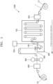
- FIG. 1 is a process diagram schematically illustrating a method of manufacturing a hot dip galvanizing steel plate according to an embodiment of the present disclosure.
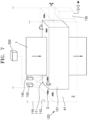
- FIG. 2 is a perspective view schematically illustrating a hot dip galvanizing facility in the method of manufacturing a hot dip galvanizing steel plate in FIG. 1 .
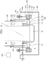
- FIG. 3 is a cross-sectional view schematically illustrating the side of a snout control system installed in the hot dip galvanizing facility of FIG. 2 .
- FIG. 4 is a cross-sectional view schematically illustrating the front of the snout control system installed in the hot dip galvanizing facility of FIG. 2 .
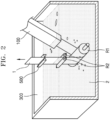
- FIG. 5 is a perspective view schematically illustrating the inside of the snorkel part of a snout apparatus of FIG. 4 .
- FIG. 6 is a cross-sectional view schematically illustrating the front of the snout control system installed in the hot dip galvanizing facility of FIG. 2 .
- FIG. 7 is a perspective view schematically illustrating the inside of snorkel part of the snout apparatus of FIG. 6 .
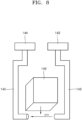
- FIGS. 8 and 9 are diagrams schematically illustrating a construction that protects the lens of a machine vision camera against zinc vapor according to an embodiment of the present disclosure.
- the processor 200 may be implemented with a central processing unit (CPU), a digital signal processor (DSP), a micro controller unit (MCU), or a system on chip (SoC), may control a plurality of hardware or software components connected to the processor 200 by driving an operating system or an application, may perform various types of data processing and operations, and may be constructed to execute at least one instruction stored in memory (not illustrated) and to store the resulting data of the execution in the memory (not illustrated).
- CPU central processing unit
- DSP digital signal processor
- MCU micro controller unit
- SoC system on chip
- a steel plate 1 that has been coiled after cold rolling or hot rolling is mounted on a payoff reel C1. Welding between a preceding steel plate 1 and a following steel plate 1 is completed through the welding facility 600. Heat treatment may be performed on the steel plate 1 in the heating facility 700 in order to secure desired material strength and plating adhesion upon hot dip galvanizing.
- the steel plate 1 on which the heat treatment has been completed may be input to the plating bath 300 of the hot dip galvanizing facility in the state in which the steel plate has been maintained at a temperature suitable for a dip galvanizing process.
- the steel plate may be input through the snout apparatus 100, that is, a steel plate induction facility, in order to prevent the oxidation of a surface of the steel plate 1 which occurs because the steel plate 1 on which the heat treatment has been performed at a high temperature is exposed to the atmosphere and a plating peeling phenomenon attributable to the exposure of the steel plate.
- the snout apparatus 100 may have one side connected to the heating facility 700 and the other side immersed in a bath surface of the plating bath 300, so that the steel plate 1 on which the heat treatment has been performed in the heating facility 700 may be introduced into the plating bath 300 in which a hot dip galvanizing solution 2 has been accommodated.
- the inside of the snout apparatus 100 may be filled with inert gas (NHx) in order to prevent plating peeling attributable to the oxidation of a surface of the steel plate 1.
- NHx inert gas
- the amount of plating attached to the steel plate may be adjusted to a preset thickness by the air knife 500 that is installed above the plating bath 300 and that adjusts the thickness of the molten zinc attached to the steel plate 1.
- the steel plate 1 on which the plating has been completed as described above may be fabricated in the state in which a surface of the steel plate is beautiful through temper rolling in the rolling facility 800. Thereafter, the steel plate may be finally commercialized by being wound on tension reel C2 through a shape corrector, post-processing for securing corrosion resistance, and the post-processing facility 900 including a cutter.
- the steel plate 1 may be introduced into the plating bath 300 in which the hot dip galvanizing solution 2 has been accommodated, by the snout apparatus 100 that is connected to the heating facility 700 and that has one end immersed in a bath surface of the hot dip galvanizing solution 2 that has been accommodated in the plating bath 300, a first sensor 160 that is disposed above a part of the plating bath 300 and that may measure a first water level of a bath surface of the hot dip galvanizing solution 2, and the processor 200 that controls the first sensor.
- the steel plate 1 may be consecutively transferred while the path line of the steel plate is vertically changed right above the plating bath 300, by a sink roll R1 immersed in the plating bath 300 and stabilizing rolls R2 installed right above the sink roll.
- the hot dip galvanizing solution 2 that has been accommodated in the plating bath 300 may be attached to a surface of the steel plate 1.
- the bending of the steel plate 1 that has passed through the sink roll R1 may be corrected while the steel plate passes between the pair of stabilizing rolls R2 installed right above the sink roll.
- the amount of molten zinc that is attached to a surface of the steel plate may be adjusted while the steel plate passes through the air knife 500.
- the snout apparatus 100 basically includes a snorkel part 110, a detachable dam unit 120, a pump unit 130, and the first sensor 160 capable of measuring the water level of a bath surface of the hot dip galvanizing solution 2, and may be controlled by the processor 200 that operates in conjunction with the first sensor 160.
- the snout apparatus 100 is formed to surround the steel plate 1 and has an internal space A3 filled with inert gas (NHx), and can thus prevent the oxidation of a surface of the steel plate 1 on which heat treatment has been performed at a high temperature in the heating facility 700 as the steel plate is exposed to the atmosphere. Furthermore, the snout apparatus may have a structure for preventing a surface defect from occurring because ash that is formed because vapor of the hot dip galvanizing solution 2 that has been accommodated in the plating bath 300 is condensed is attached to a surface of the steel plate 1 as alien substances.
- NHx inert gas
- the snorkel part 110 having a part immersed in a bath surface of the hot dip galvanizing solution 2 that has been accommodated in the plating bath 300 may be installed on a lower side of the snout apparatus 100. More specifically, the snorkel part 110 is formed to surround the steel plate 1 that has been introduced into the plating bath 300, and may guide the steel plate 1 so that the steel plate is introduced into the hot dip galvanizing solution 2 that has been accommodated in the plating bath 300, through an opening 111 that has been formed at a bottom thereof that has been immersed in a bath surface of the plating bath 300.
- the snorkel part further includes the detachable dam unit 120, which includes a first dam wall part 121 and a second dam wall part 122 that are physically coupled to an outer wall part of the snorkel part 110, that may be driven along an outer wall of the snorkel part 110 based on information on the first water level of a bath surface of the hot dip galvanizing solution 2 while operating in conjunction with the first sensor 160, that are spaced apart from an inner wall part 112 of the snorkel part 110 at a predetermined distance in the opening of the snorkel part 110, and that are formed along the inner circumference of the snorkel part 110 so that the first dam wall part and the second dam wall part protrude at a predetermined height in the height direction of the snorkel part 110, and which forms an accommodation space capable of accommodating the hot dip galvanizing solution 2 that runs over the first dam wall part 121 after being introduced through the opening between the second dam wall part 122 and the first dam wall part 121 spaced apart from the inner wall part 112 of the snorkel part 11.
- the detachable dam unit 120 which includes a first dam wall part
- the snorkel part 110 is formed in a rectangular tube form having a rectangular cross section, and may be coupled to the bottom of the snout apparatus 100, which is formed in the same rectangular tube form.
- the dam unit 120 that is coupled to the outer wall part of the snorkel part 110 may be driven up and down on the basis of a bath surface of the plating bath 300 by a driving apparatus, such as an actuator, so that the depth of the bottom of the dam unit, which has been immersed in the plating bath 300, is adjusted.
- the dam unit 120 is constructed in a sliding rail form and physically coupled to the outer wall part of the snorkel part 110.
- the driving apparatus (not illustrated) for driving the dam unit 120 may be connected to any part of the snout apparatus 100.
- a cooling pipe (not illustrated) for water cooling may be formed along the outer circumferential surface of the motor.
- the dam unit 120 includes the first dam wall part 121 and the second dam wall part 122 that are spaced apart from the inner wall part 112 of the snorkel part 110 at a predetermined distance and formed along the inner circumference of the snorkel part 110 so that the first dam wall part and the second dam wall part protrude at a predetermined height in the height direction of the snorkel part 110, in the opening 111 of the snorkel part 110, and may thus form an accommodation space A1 capable of accommodating the hot dip galvanizing solution 2 that run over the first dam wall part 121 after being introduced through the opening 111 between the second dam wall part 122 and the first dam wall part 121 spaced apart from the inner wall part 112 of the snorkel part 110.
- the second dam wall part 122 is formed to have a relatively higher height than the first dam wall part 121. This may cause a problem in the raising and lowering driving of the dam unit 120 when alien substances D that approach the steel plate 1 are moved toward the second dam wall part 122 and the outer wall part of the snorkel part 110. Accordingly, by forming the second dam wall part 122 to have a higher height than the water level of a bath surface of the hot dip galvanizing solution 2, the alien substances D that approach the steel plate 1 can be physically blocked from approaching the driving part of the dam unit 120.
- the dam unit 120 is coupled to the outer wall part of the snorkel part 110, and forms the accommodation space A1 that is formed by the first dam wall part 121 having a form in which the first dam wall part has been bent toward the opening 111 of the snorkel part 110.
- a part of the dam unit 120 may be formed to have the same height as a bath surface of the hot dip galvanizing solution 2 that has been introduced through the opening 111 of the snorkel part 110 or may be formed at a relatively lower location than the bath surface of the hot dip galvanizing solution 2 in the state in which the snorkel part 110 has been immersed in the plating bath 300 or has been formed at a relatively higher location than a bath surface of the hot dip galvanizing solution 2.
- the hot dip galvanizing solution 2 that is introduced through the opening 111 of the snorkel part 110 may run over the first dam wall part 121a and may be accommodated in the accommodation space A1 of the dam unit 120.
- the pump unit 130 is installed outside the snorkel part 110, and may discharge, to the plating bath 300, the hot dip galvanizing solution 2 that has been accommodated in the accommodation space A1 of the dam unit 120 by pumping the hot dip galvanizing solution.
- the pump unit 130 is installed at a location corresponding to the dam unit 120 outside the snorkel part 110, so that a pumping space A2 within the pump unit is connected to the accommodation space A1 of the dam unit 120 in a way to communicate with the accommodation space.
- the pump unit 130 includes a housing part 131 having an outlet 131a formed on one side thereof so that the hot dip galvanizing solution 2 that is introduced from the accommodation space A1 to the pumping space A2 is discharged to the plating bath 300.
- the pump unit may include an impeller part 132 that is rotatably installed in the pumping space A2 of the housing part 131 and that runs the hot dip galvanizing solution 2 that is introduced into the pumping space A2 toward the outlet 131a by its rotation driving, and a driving motor that is installed on one side of the housing part 131 by a bracket B installed on the side of the dam unit 120 and that rotates and drives the impeller part 132 having a rotation shaft 132a connected to a rotation shaft 133a.
- the pump unit 130 may induce the hot dip galvanizing solution 2 within the plating bath 300 to be continuously introduced through the opening 111 of the snorkel part 110, by discharging, to a bath surface of the plating bath 300 outside the snorkel part 110, the hot dip galvanizing solution 2 that runs over the first dam wall part 121 after being introduced through the opening 111 of the snorkel part 110 and that is accommodated in the accommodation space A1 of the dam unit 120.
- the pump unit 130 induces the alien substances D, such as dross included in the hot dip galvanizing solution 2, to float on a bath surface of the plating bath 300 by discharging, to the bath surface of the plating bath 300 outside the snorkel part 110, the hot dip galvanizing solution 2 that has been accommodated in the accommodation space A1 of the dam unit 120. It is possible to prevent the alien substances D from being mixed with the hot dip galvanizing solution 2 within the plating bath 300 and thus contaminating the hot dip galvanizing solution 2 again or to prevent the alien substances from being introduced through the opening 111 of the snorkel part 110 again, which has a bottom immersed below a bath surface of the plating bath 300.
- the alien substances D such as dross included in the hot dip galvanizing solution 2
- the alien substances D such as dross that is discharged to the bath surface of the plating bath 300 by the pump unit 130 and that floats on the bath surface of the plating bath 300, may be removed from the bath surface of the plating bath 300 by a separate removal apparatus or may be removed by a worker.
- a form of the pump unit 130 is not essentially limited to the form of FIGS. 3 to 5 .
- Various forms in which the hot dip galvanizing solution 2 accommodated in the accommodation space A1 of the dam unit 120 can be discharged toward the bath surface of the plating bath 300 outside the snorkel part 110 may be applied to the form of the pump unit.
- the snout apparatus 100 may further include second sensors 140 and 150 that are installed on any one side of an internal space of the snorkel part 110 and that measure a second water level of a bath surface of the hot dip galvanizing solution 2 that is introduced into the opening 111, runs over the first dam wall part 121, and is accommodated in the accommodation space A1 of the dam unit 120 and that detect the alien substances D that float on the bath surface of the hot dip galvanizing solution 2 introduced into the snorkel part 110 through the opening and that approach the steel plate 1.
- second sensors 140 and 150 that are installed on any one side of an internal space of the snorkel part 110 and that measure a second water level of a bath surface of the hot dip galvanizing solution 2 that is introduced into the opening 111, runs over the first dam wall part 121, and is accommodated in the accommodation space A1 of the dam unit 120 and that detect the alien substances D that float on the bath surface of the hot dip galvanizing solution 2 introduced into the snorkel part 110 through the opening and that approach the steel plate 1.
- the second sensors 140 and 150 may measure the second water level of the bath surface of the hot dip galvanizing solution 2 that is introduced into the opening 111, by using any one of an ultrasonic sensor, an infrared sensor, and a radar sensor. Furthermore, the second sensors 140 and 150 may detect the alien substances D that float on the bath surface of the hot dip galvanizing solution 2. Any one of the second sensors 140 and 150 may be a vision sensor that detects the alien substances D that float on the bath surface of the hot dip galvanizing solution 2 by using a camera image sensor in addition to the sensors.
- the types of second sensors 140 and 150 may be selectively changed so that any one of the second sensors can measure the second water level of the bath surface of the hot dip galvanizing solution 2 by using any one of an ultrasonic sensor, an infrared sensor, and a radar sensor and the other of the second sensors can detect the alien substances D that float on the bath surface of the hot dip galvanizing solution 2 by using a vision sensor.
- any one 140 of the second sensors 140 and 150 may be disposed between one side of the steel plate 1 and the inner wall of the snorkel part 110.
- the other 150 of the second sensors 140 and 150 may be disposed between the other side of the steel plate 1 and the inner wall of the snorkel part 110.
- the laser sensor may detect and recognize that the alien substances D are present when recognized values according to a difference between reflectance in the alien substances D that float on a bath surface of the hot dip galvanizing solution 2 and reflectance on the bath surface of the hot dip galvanizing solution 2 in a normal state are different from each other.
- the normal state means the state in which only the hot dip galvanizing solution 2 that is pure without the alien substances D is present.
- the flow velocity of an overflow from the inside of the dam unit 120 to the outside is increased when the amount of the overflow through the lowering of the dam unit 120 is increased.
- the gap G between the first water level measured by the first sensor 160 and the first dam wall part 121 can be constantly automatically controlled by increasing the RPM of the pump unit 130 according to an increase of the amount of an overflow.
- any one sensor 140 of the second sensors 140 and 150 may be implemented with a camera module, that is, a vision sensor having an auto-focusing function or a raising and lowering function.
- the second sensor 150 other than the camera module may be implemented with any one of an ultrasonic sensor, an infrared sensor, and a radar sensor (reference numerals are written side by side in order to indicate that the second sensor 150 indicated hereinafter corresponds to the second sensor other than the camera module 140 for a clear distinction between terms).
- the recognition rate of the alien substances D that float on the bath surface of the hot dip galvanizing solution 2 can be improved by the function of the camera module 140.
- Images of the alien substances D that are measured by the camera module 140 are repeatedly learnt, and image signals according to the sizes and forms of the alien substances D are transmitted to the processor 200.
- the processor adjusts the location of the dam unit 120 or controls a load of the pump unit 130 based on the image signal.
- an image library of the alien substances D on bath surfaces of the hot dip galvanizing solution 2 is constructed through pre-image learning by using the camera module 140, and images thereof are stored in a data repository of the processor 200.
- the flow velocity of the overflow from the inside of the dam unit 120 to the outside is increased by comprehensively considering information on the gap G between the first water level measured by the first sensor 160 and the dam wall part 121 and information on the load of the pump unit 10 While receiving real-time information of the alien substances D that float on a bath surface of the hot dip galvanizing solution 2 based on the learning data of the constructed image library of the alien substances D.
- the gap G between the first water level measured by the first sensor 160 and the first dam wall part 121 may be constantly automatically controlled by increasing the RPM of the pump unit 130 according to an increase of the amount of an overflow.
- the processor 200 is electrically connected to the first sensor 160 and the second sensors 140 and 150, and the processor may receive sensing signals from the first sensor 160 and the second sensors 140 and 150 and may raise or lower the dam unit 120 based on a sensing signal so that the depth of the dam unit 120 immersed in the plating bath 300 can be adjusted or may adjust a load of the pump unit 130 so that the rate of flow of the hot dip galvanizing solution 2 that is pumped by the pump unit 130 can be controlled.
- the processor 200 can constantly maintain the gap G by controlling the hot dip galvanizing solution 2 so that some of the hot dip galvanizing solution rapidly exits to the outside through the accommodation space A2 of the pump unit 130 by controlling a load of the pump unit 130 by considering the case in which the gap G is greatly increased.
- the processor 200 can constantly maintain the gap G between a protrusion part that protrudes to the first dam wall part 121 and a bath surface of the hot dip galvanizing solution 2, by deriving information on the gap by combining the first water level of the bath surface of the hot dip galvanizing solution 2, which is detected through the first sensor 160, and information on the location of the first dam wall part 121 of the dam unit 120 and controlling the location of the dam unit 120 based on the derived information on the gap and information on a load of the pump unit 130.
- the gap may satisfy a range of 10 mm to 20 mm.
- the flow velocity at which the alien substances D are discharged needs to be greater than a critical point in order for the alien substances to be discharged to the outside through the dam unit 120. If the gap is less than 10 mm, the alien substances D cannot be effectively discharged because it is not easy for the gap to generate a flow velocity at which the alien substances D can be moved to be discharged to the outside. In contrast, if the gap is greater than 20 mm, the flow velocity of the alien substances D is greater than a load of the pump unit 130 because the flow velocity of the alien substances becomes fast. Accordingly, in order to solve such a problem, the gap needs to maintain 10 mm to 20 mm.
- the heights of a bath surface of the hot dip galvanizing solution 2 that has been introduced into the snorkel part 110 and the top of the first dam wall part 121 become similar. Accordingly, a flow of the hot dip galvanizing solution 2, which has been introduced into the snorkel part 110 through the opening 111 of the snorkel part 110, into the accommodation space A1 of the dam unit 120 may be weakened because the hot dip galvanizing solution 2 runs over the first dam wall part 121. In such a case, a flow of the alien substances D that float on the bath surface of the hot dip galvanizing solution 2 within the snorkel part 110 may also be weakened. Accordingly, as the time during which the alien substances float around the steel plate 1 is increased, the probability that a failure may be caused may be increased because the alien substances D are attached to the steel plate 1.
- the alien substances D that float on a bath surface of the hot dip galvanizing solution 2 within the snorkel part 110 can be prevented from being attached to the steel plate 1 and the lifespan of the pump unit 130 can also be increased because the pump unit 130 maintains a proper load, by controlling the water level difference H while raising or lowering the dam unit 120 so that the water level difference H according to the first water level and the information on the location of the first dam wall part 121 of the dam unit 120 is constantly maintained.
- the processor 200 may increase the depth of the bottom of the dam unit 120, which has been immersed in the plating bath 300, by lowering the dam unit 120 when the location of the dam unit 120 is smaller than a preset reference, and may reduce the depth of the bottom of the dam unit 120, which has been immersed in the plating bath 300, by raising the dam unit 120 when the location of the dam unit 120 is greater than the reference.
- the processor may induce a flow of the hot dip galvanizing solution 2 that is introduced through the opening 111 and that runs over the first dam wall part 121 to be reduced so that the water level difference H is increased, by raising the dam unit 120 so that the depth of the top of the first dam wall part 121, which has been immersed, is reduced from the bath surface of the hot dip galvanizing solution 2 introduced into the snorkel part 110.
- the first water level of a bath surface of the hot dip galvanizing solution 2 is recognized by using a flow of the alien substances D around the dam unit 120 within the snorkel part 110 of the snout apparatus 100 and the first sensor 160, and the water level difference H according to information on the location of the dam unit 120 is recognized through the second sensors 140 and 150. Accordingly, when the alien substances D around the dam unit 120 approach the steel plate 1, the mixture of the alien substances D into the steel plate 1 can be prohibited by automatically controlling the depth of the bottom of the dam unit 120, which has been immersed in the plating bath 300, by raising or lowering the dam unit 120 of the snout apparatus 100.
- the gap between the first water level and the second water level needs to be controlled to be at least 80 mm or more by considering a load of the pump unit 130.
- the management of the dam within the snout apparatus 100 is automatically controlled by detecting the water level difference H according to the first water level and information on the location of the dam unit 120 by using the second sensors 140 and 150 capable of detecting the alien substances D that float on a bath surface within the snorkel part 110 of the snout apparatus 100 or detecting the location of the dam unit 120 and the first sensor 160 capable of detecting the first water level of a bath surface of the hot dip galvanizing solution 2. Accordingly, it is possible to achieve an effect in that work convenience and quality stability are secured.
- the recognition of the alien substances D that float on a bath surface of the hot dip galvanizing solution 2 is adversely affected because the lens of the camera module 140 disposed within the snorkel part 110 is contaminated due to zinc vapor that evaporates from the hot dip galvanizing solution 2.
- the contamination of the lens is prevented by using methods illustrated in FIGS. 8 and 9 .
- FIGS. 8 and 9 are diagrams schematically illustrating a construction that protects the lens of a machine vision camera against zinc vapor according to an embodiment of the present disclosure.
- the snout apparatus 100 of the present disclosure further includes a gas supply part 142 and a gas suction part 144 so that inert gas capable of removing zinc vapor by absorbing the zinc vapor or reaction gas that generates reactions with the zinc vapor can be supplied.
- the snout apparatus also includes a gas supply pipe 143 and a gas suction pipe 145 that are formed so that gas can be supplied to a surface of the lens provided on one side of the camera module 140 by supplying gas to the surrounding of the camera module 140 and gas can be sucked.
- the supply of gas may be always performed while zinc plating is performed.
- the gas supply pipe 143 and the gas suction pipe 145 may be formed in an area out of the sensing area of the lens so that the camera module 140 is not influenced to detect the alien substances D that float on a bath surface of the hot dip galvanizing solution 2.
- the snout apparatus 100 of the present disclosure is filled with inert gas in order to prevent plating peeling attributable to the oxidation of a surface of the steel plate 1.
- the snout apparatus may further include a swirling flow generation apparatus (not illustrated) capable of generating a swirling flow by rotating inert gas that is supplied to the snout on a surface of the lens of the camera module 140.
- Zinc vapor can be adsorbed by the inert gas and removed toward a separate pipe (not illustrated) by the swirling flow.
- a worker is in a work environment in which a risk of mass defects is high because the worker controls the location of the dam unit 120 by constantly monitoring the dam unit.
- the processor 200 automatically controls the location of the dam unit 120 based on the water level of a bath surface of the hot dip galvanizing solution 2.
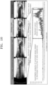
- FIG. 10 is an exemplary diagram for describing a flow of alien substances on a bath surface according to an embodiment of the present disclosure.
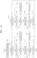
- FIG. 11 is a flowchart for describing a snout control method according to an embodiment of the present disclosure.
- the embodiment 2 is focused on an automatic control construction of the snout apparatus by the processor 200, and the structure of a hot dip galvanizing facility that is premised by the embodiment 2 and detailed components thereof are the same as those of the embodiment 1.
- the processor 200 may recognize a difference between the heights of the water level of a bath surface that is measured by the first sensor 160 and the dam unit 120, may recognize at least one of a structure within the snorkel part 110 and alien substances on the bath surface based on an image that is captured by the camera module 140, and may control the snout apparatus 100 based on at least one of the recognized difference between the heights, the recognized structure within the snorkel part 110, and the recognized alien substances on the bath surface.
- the processor 200 monitors a change in the water level of a bath surface in real time through the first sensor 160, monitors the present work condition within the snorkel part 110 in real time by analyzing an image that is captured by the camera module 140, and controls the raising or lowering of the snout apparatus 100 based on the results of the monitoring so that a process trouble and a human error can be prevented.
- the processor 200 may recognize a difference between the heights of the water level of the bath surface and the dam unit 120, and may compare the difference between the heights of the water level of the bath surface and the dam unit 120 with a preset reference value.
- the reference value is a preset value, and may be 2 mm, for example.
- the difference between the heights of the water level of the bath surface and the dam unit 120 may mean a difference between the heights of the water level of the bath surface and the first dam wall part 121.
- the difference between the heights of the water level of the bath surface and the dam unit 120 may mean a difference between the heights of the water level of the bath surface and the top of the first dam wall part 121.
- the processor 200 may monitor a flow on the bath surface to the inside/outside of the dam unit 120 within the snout apparatus 100 by applying a computer vision technique to the image that is captured by the camera module 140. That is, the processor 200 may monitor a work situation within the snout apparatus 100 by analyzing an internal structure according to the water level of the bath surface and a flow of alien substances that float on the bath surface by using the image that is captured by the camera module 140.
- the processor 200 may determine whether the structure recognized through the object recognition algorithm is present at a preset and predetermined ratio or more.
- the predetermined ratio is 90%, for example, and may be an arbitrarily set value.
- the processor 200 may recognize the alien substances on the bath surface, which float on the bath surface within the snorkel part 110 and approach the steel plate 1, by applying an optical flow to the image that is captured by the camera module 140. That is, the processor 200 may use the optical flow, that is, one of image processing techniques, in order to monitor a flow of the alien substances that float on the bath surface.
- the optical flow is a technique capable of recognizing an optical flow within an image as a vector map indicative of motions of pixels between two consecutive frames. If the optical flow is used, there is an advantage in that a movement of an object within an image that is captured by CCTV or a common camera can be monitored even without an expensive machine vision camera.
- the optical flow is basically represented as a colormap, and may indicate a direction as H (color) and a size as S (chroma).
- the processor 200 indicates a first color when alien substances are mixed into the dam unit 120 and indicates a second color when alien substances are discharged to the outside of the dam unit 120 so that the present work condition within the snorkel part 110 can be monitored in real time. That is, the optical flow may indicate that alien substances are mixed into the dam unit 120 when the direction of a flow of the alien substances that float on the bath surface is a backward direction, and may indicate that alien substances are discharged to the outside of the dam unit 120 when the direction of a flow of the alien substances that float on the bath surface is a forward direction.
- the processor 200 may indicate a red color when alien substances on a bath surface are mixed into the dam unit 120, and may indicate a green color when alien substances are discharged to the outside of the dam unit 120.
- the processor 200 digitizes the vector sum of the mixing of alien substances on a bath surface into the snorkel part 110 and the discharge of alien substances in real time so that the present work condition within the snorkel part 110 can be analyzed in real time.
- the processor 200 may generate the vector sum of the mixing of the alien substances on the bath surface into the snorkel part 110 and the discharge of the alien substances, as illustrated in FIG. 10 .
- the processor 200 may control the snout apparatus 100 based on at least one of the difference between the heights of the water level of the bath surface and the dam unit 120, the structure within the snorkel part 110, and the alien substances on the bath surface.
- the processor 200 may maintain the height of the snout apparatus 100 by determining that the present work condition within the snorkel part 110 is normal.
- the processor 200 may raise the height of the snout apparatus 100 by determining that the alien substances on the bath surface are mixed into the dam unit 120. In this case, as the alien substances on the bath surface are introduced into the dam unit 120, the processor 200 may raise the height of the snout apparatus 100 so that the alien substances on the bath surface are discharged to the outside of the dam unit 120.
- the depth of the bottom of the dam unit, which has been immersed in the plating bath 10 can be reduced because the dam unit 120 is also raised when the height of the snout apparatus 100 is raised. Accordingly, the alien substances on the bath surface within the dam unit 120 can be discharged to the outside of the dam unit 120.
- the processor 200 may raise the snout apparatus 100 so that the structure is present at the predetermined ratio or more.
- the structure being not present in the image at the predetermined ratio or more means that the structure has been much immersed in the bath surface. This means that the water level within the dam unit 120 is high. Accordingly, it is necessary to discharge the alien substances on the bath surface within the dam unit 120 to the outside of the dam unit. Accordingly, the processor 200 may discharge the alien substances on the bath surface within the dam unit 120 to the outside of the dam unit 120 by raising the snout apparatus 100.
- the processor 200 may maintain the height of the snout apparatus 100 by determining that the present work condition within the snorkel part 110 is normal.
- the processor 200 may lower the height of the snout apparatus 100.
- the processor 200 may lower the snout apparatus 100 in order to discharge the alien substances on the bath surface to the outside of the dam unit 120 because the alien substances that float on the bath surface is in the state in which the alien substances have been mixed into the dam unit 120 and the dam unit 120 is high. That is, the alien substances on the bath surface within the dam unit 120 can be discharged to the outside of the dam unit 120 because the dam unit 120 is also lowered when the snout apparatus 100 is lowered.
- the processor 200 may lower the snout apparatus 100 so that the structure is present at the predetermined ratio or more.
- the structure being not present in the image at the predetermined ratio or more means that the structure has been much immersed in the bath surface. This means that the water level within the dam unit 120 is high. Accordingly, it is necessary to discharge the alien substances on the bath surface within the dam unit 120 to the outside of the dam unit.
- the processor 200 may lower the snout apparatus 100 in order to discharge the alien substances on the bath surface to the outside of the dam unit 120 because the dam unit 120 is high. Accordingly, the alien substances within the dam unit 120 can be discharged to the outside of the dam unit 120.
- the processor 200 may automatically control the depth of the bottom of the snout apparatus 100, which has been immersed in the plating bath 10, by controlling the snout apparatus 100 based on at least one of the difference between the heights of the water level of the bath surface and the dam unit 120, the structure within the snorkel part 110, and the alien substances on the bath surface, and may monitor the present work condition within the snorkel part 110 in real time. Accordingly, it is possible to achieve an effect in which work convenience and quality stability are secured. Furthermore, the processor 200 can prevent alien substances from adhering to the steel plate 1 in a hot dip galvanizing process by automatically controlling the immersed depth of the snout apparatus 100 when the alien substances approach the steel plate 1.
- the processor 200 may monitor a change in the water level of a bath surface in real time through the first sensor 160, may detect a degree of the occurrence of a risk by analyzing the present work condition within the snorkel part 110 in real time by using a computer vision technique, and may automatically control the snout apparatus 100 based on the results of the detection so that process automation can be finally implemented by preventing a process trouble and a human error.
- the snout control system can suppress the mixing of alien substances into the steel plate 1 by raising or lowering the snout apparatus 100 based on at least one of a difference between the heights the water level of a bath surface and the dam unit 120 of the snout apparatus 100, a structure within the snorkel part 110, and a flow of the alien substances on the bath surface.
- FIG. 11 is a flowchart for describing a snout control method according to an embodiment of the present disclosure.
- the processor 200 receives the water level of a bath surface, which is measured through the first sensor 160, and an image that is captured by the camera module 140 (S602).
- step S602 the processor 200 calculates a difference between the heights of the water level of the bath surface and the dam unit 120, and determines whether the calculated difference between the heights is equal to or greater than a reference value (S604).
- the processor 200 recognizes a preset structure (S606) by using the image captured by the camera module 140, and determines whether the recognized structure is present at a preset and predetermined ratio or more (S608).
- the processor 200 may recognize the structure within the snorkel part 110 by applying an object recognition algorithm to the image.
- the processor 200 recognizes a flow of the alien substances on the bath surface based on the image (S610), and determines whether the direction of the flow of the alien substances on the bath surface is a forward direction (S612).
- the processor 200 may recognize the flow of the alien substances on the bath surface, which float on the bath surface within the snorkel part 110 and approach the steel plate 1, by applying an optical flow.
- the direction of the flow of the alien substances on the bath surface being the forward direction may mean that the alien substances floating on the bath surface are discharged.
- the direction of the flow of the alien substances on the bath surface being a backward direction may mean that the alien substances are mixed into the bath surface.
- the processor 200 maintains the height of the snout apparatus 100 (S614). That is, when the direction of the flow of the alien substances on the bath surface is a forward direction, the processor 200 may maintain the height of the snout apparatus 100 because it is meant that the alien substances on the bath surface are normally discharged to the outside of the dam unit 120.
- the processor 200 raises the height of the snout apparatus 100 (S616). That is, when the direction of the flow of the alien substances on the bath surface is a backward direction, it is necessary to discharge the alien substances that are mixed to the outside of the dam unit 120 because the alien substances are mixed into the bath surface. Accordingly, the processor 200 may raise the height of the snout apparatus 100. When the height of the snout apparatus 100 is raised, the height of the dam unit 120 is also raised. Accordingly, the alien substances on the bath surface can be discharged to the outside of the dam unit 120.
- the processor 200 raises the snout apparatus 100 so that the structure is present at the predetermined ratio (S618).
- the structure being not present in the image at the predetermined ratio or more means that the structure has been much immersed in the bath surface. This means that the water level within the dam unit 120 is high. Accordingly, it is necessary to discharge the alien substances on the bath surface within the dam unit 120 to the outside. Accordingly, the processor 200 may discharge the alien substances on the bath surface to the outside of the dam unit 120 by raising the snout apparatus 100.
- the processor 200 determines whether the difference between the heights is less than the reference value (S620).
- the processor 200 recognizes a preset structure by using the image captured by the camera module 140 (S622), and determines whether the structure is present at a preset and predetermined ratio or more (S624). In this case, the processor 200 may recognize the structure within the snorkel part 110 by applying an object recognition algorithm to the image.
- the processor 200 recognizes a flow of the alien substances on the bath surface based on the image (S626), and determines whether the direction of the direction of the flow of the alien substances on the bath surface is a forward direction (S628). In this case, the processor 200 may recognize the flow of the alien substances on the bath surface, which float on the bath surface within the snorkel part 110 and approach the steel plate 1, by applying an optical flow.
- the processor 200 maintains the height of the snout apparatus 100 (S630).
- the processor 200 may maintain the height of the snout apparatus 100 by determining that the present work condition within the snorkel part 110 is normal.
- the processor 200 lowers the height of the snout apparatus 100 (S632).
- the processor 200 may lower the snout apparatus 100 in order to discharge the alien substances on the bath surface to the outside of the dam unit 120 because the alien substances that float on the bath surface are in the state in which the alien substances have been mixed into the dam unit 120 and the dam unit 120 is high. Accordingly, the alien substances within the dam unit 120 can be discharged to the outside of the dam unit 120.
- the processor 200 lowers the snout apparatus 100 so that the structure is present at the predetermined ratio (S634).
- the structure being not present in the image at the predetermined ratio or more means that the structure has been much immersed in the bath surface. This means that the water level within the dam unit 120 is high. Accordingly, it is necessary to discharge the alien substances on the bath surface within the dam unit 120 to the outside.
- the processor 200 may lower the snout apparatus 100 in order to discharge the alien substances on the bath surface to the outside of the dam unit 120 because the dam unit 120 is high. Accordingly, the alien substances within the dam unit 120 can be discharged to the outside of the dam unit 120.
- the snout apparatus is automatically controlled based on at least one of the water level of a bath surface measured through the sensor, a structure within the snorkel part based on an image captured by the camera, and alien substances on the bath surface. Accordingly, it is possible to achieve effects in that the present work condition within the snorkel part can be monitored in real time and thus work convenience and quality stability can be secured.
- a change in the water level of a bath surface is monitored in real time through the sensor, the present work condition within the snorkel part is monitored in real time by analyzing an image captured by the camera, and the raising or lowering of the snout apparatus is controlled based on the results of the monitoring.
- an implementation described in this specification may be realized as a method or process, an apparatus, a software program, a data stream, or a signal, for example.
- the apparatus may be implemented as proper hardware, software, or firmware.
- the method may be implemented in an apparatus, such as a processor commonly referring to a processing device, including a computer, a microprocessor, an integrated circuit, or a programmable logic device, for example.
- the processor includes a communication device, such as a computer, a cell phone, a mobile phone/personal digital assistant ("PDA”), and another device which facilitate the communication of information between end users.
- PDA mobile phone/personal digital assistant
Landscapes
- Chemical & Material Sciences (AREA)
- Engineering & Computer Science (AREA)
- Chemical Kinetics & Catalysis (AREA)
- Materials Engineering (AREA)
- Mechanical Engineering (AREA)
- Metallurgy (AREA)
- Organic Chemistry (AREA)
- Computer Hardware Design (AREA)
- Coating With Molten Metal (AREA)
Abstract
Description
- The present disclosure relates to a snout control system and a hot dip galvanizing facility including the same, and more particularly, to a snout control system capable of automatically removing dross that floats within a snout apparatus during a process of producing a hot dip galvanizing steel plate and a hot dip galvanizing facility including the same.
- A hot dip galvanizing facility is a molten metal facility that plates zinc coating on a surface of a steel plate having a high temperature by dissolving a zinc ingot into a high temperature melting state having 450 degrees or higher. In the hot dip galvanizing facility, dross having an Fe2Al structure, that is, an intermetallic compound, always occurs due to a temperature difference with ambient air and thermal and chemical instability, such as zinc oxidation attributable to a contact with discharging wiping air of an air knife that floats on a molten metal surface after colliding against a vertical strip surface. In particular, as various alloy element components, such as aluminum, manganese, and silicon, are added in order to enhance the corrosion-resistance of a plating steel plate, improve surface quality, etc., the amount of dross occurred is greatly increased due to external factors (a temperature difference, oxidation according to a wiping gas contact, etc.).
- Such dross is adsorbed on a surface of the steel plate, and may cause various problems, such as a processing crack, plating peeling, the deterioration of coating properties, etc. during secondary processing. In particular, in order for the plating steel plate to be supplied for the cover panel of a vehicle, dross needs to be more strictly managed. In many steel companies, a lot of research is carried out even from the viewpoint of discharge management for minimizing the occurrence of dross by securing the thermal and chemical stability of a zinc plating bath so as to prohibit a dross defect and preventing alien substances, such as an ash (ZnO oxidation substances) defect, in addition to dross and floating matters on a molten metal surface, including both the alien substances and dross from being adsorbed onto the steel plate, by introducing a facility having a dam structure into a snout that has one end immersed in the zinc plating bath and that introduces the steel plate.
- In general, many steel companies use a snout control system using a method of discharging dross that has crossed out to a dam to the back of a zinc plating bath, by using a structure having a dam form and a metal pump facility within the snorkel part of a snout apparatus in order to remove dross that floats within the snout apparatus.
- The Background Art of the present disclosure was disclosed in
Korean Patent Application Publication No. 10-2014-0085175 - However, such a conventional snout control system and a hot dip galvanizing facility including the same have a problem in that a defect occurs due to the adhesion of alien substances to a steel plate, because a case in which a dam is fully filled because the level of a zinc plating bath is too high during work or alien substances of dross, etc. are not discharged to the outside of the dam because the level of the zinc plating bath is too low frequently occurs. Furthermore, due to such a problem, there is a problem in that it is difficult for workers to handle dross management unless the workers monitor dam management within a snout apparatus according to a real-time change in the molten metal level of the zinc plating bath in real time, such as that the workers frequently check and manage the present dam management situation within the snout apparatus through hand work.
- Furthermore, a snorkel part connected to the snout apparatus is integrally fabricated by being welded to the dam therein. In this case, the steel plate needs to be cut in order to replace the snorkel part, and thus there is a problem with productivity because a maintenance time for equipment is increased. Furthermore, there is a structural problem in that it is difficult to precisely process a surface of the dam. Accordingly, an object is to provide a snout control system capable of securing work convenience and quality stability and a hot dip galvanizing facility including the same, by applying a detachable dam and the detachable dam according to a real-time change in the molten metal level of the zinc plating bath and improving the aforementioned problems by automatically controlling the loads of the detachable dam and a pump unit based on the molten metal level by using a machine vision camera and a sensor.
- Furthermore, an object of the present disclosure is to provide a snout control system and method, which enable work convenience and quality stability to be secured by automatically analyzing the present work condition within a snout apparatus in real time.
- Objects to be solved by the present disclosure are not limited to the aforementioned object(s), and the other object(s) not described above may be evidently understood from the following description by those skilled in the art.
- A snout control system according to an aspect of the present disclosure includes a snout apparatus configured to have one end immersed in a plating bath in which a hot dip galvanizing solution to plate a hot dip galvanizing steel plate has been accommodated during a process of producing the steel plate and to introduce the steel plate into the plating bath; a first sensor disposed on any part of the plating bath and capable of measuring a first water level of a bath surface of the hot dip galvanizing solution; and a processor configured to control the snout apparatus and the first sensor. The snout apparatus includes a snorkel part configured to surround the steel plate that is introduced into the plating bath and to guide the steel plate so that the steel plate is introduced into the hot dip galvanizing solution accommodated in the plating bath through an opening that is formed at a bottom thereof, which has been immersed in the bath surface of the plating bath; a dam unit physically coupled to an outer wall part of the snorkel part as a detachable structure, capable of being driven along an outer wall of the snorkel part based on information on the first water level of the bath surface of the hot dip galvanizing solution while operating in conjunction with the first sensor, including a first dam wall part that is spaced apart from an inner wall part of the snorkel part at a predetermined distance and that is formed along an inner circumference of the snorkel part so that the first dam wall part protrudes at a predetermined height in a height direction of the snorkel part in the opening of the snorkel part and a second dam wall part that is spaced apart from the first dam wall part at a predetermined distance and that is exposed to the bath surface of the hot dip galvanizing solution, and configured to form an accommodation space capable of accommodating the hot dip galvanizing solution that is introduced through the opening between the inner wall part of the snorkel part and the first dam wall part and that then runs over the first dam wall part; and a pump unit installed outside the snorkel part and configured to pump the hot dip galvanizing solution accommodated in the accommodation space of the dam unit to the plating bath. The processor automatically controls a location of the dam unit based on a difference of a gap G between the first water level measured by the first sensor and the first dam wall part so that the gap is constantly maintained.
- A snout control system according to another aspect of the present disclosure includes a snout apparatus configured to have one end immersed in a plating bath in which a hot dip galvanizing solution to plate a hot dip galvanizing steel plate has been accommodated during a process of producing the steel plate and to introduce the steel plate into the plating bath; a first sensor disposed on any part of the plating bath and capable of measuring a first water level of a bath surface of the hot dip galvanizing solution; and a processor configured to control the snout apparatus and the first sensor. The snout apparatus includes a dam unit physically coupled to an outer wall part of the snorkel part as a detachable structure, capable of being driven along an outer wall of the snorkel part based on information on the first water level of the bath surface of the hot dip galvanizing solution while operating in conjunction with the first sensor, including a first dam wall part that is spaced apart from an inner wall part of the snorkel part at a predetermined distance and that is formed along an inner circumference of the snorkel part so that the first dam wall part protrudes at a predetermined height in a height direction of the snorkel part in the opening of the snorkel part and a second dam wall part that is spaced apart from the first dam wall part at a predetermined distance and that is exposed to the bath surface of the hot dip galvanizing solution, and configured to form an accommodation space capable of accommodating the hot dip galvanizing solution that is introduced through the opening between the inner wall part of the snorkel part and the first dam wall part and that then runs over the first dam wall part; a camera module installed within the snorkel part, disposed on any part of the dam unit, and capable of recognizing alien substances that float on the bath surface of the hot dip galvanizing solution; and a pump unit installed outside the snorkel part and configured to pump the hot dip galvanizing solution accommodated in the accommodation space of the dam unit to the plating bath. The processor controls a location of the dam unit or adjusts a load of the pump unit based on information that is obtained through a learning of an image of the alien substances by using the camera module so that a mixing of the alien substances that move into the steel plate is suppressed.
- In the present disclosure, the processor receives a sensing signal from the first sensor, and constantly controls the gap by constantly controlling the gap by raising or lowering the dam unit so that a depth of the dam unit that has been immersed in the plating bath is capable of being adjusted or adjusting the load of the pump unit so that a rate of flow of the hot dip galvanizing solution that is pumped by the pump unit is capable of being controlled, based on the sensing signal.
- In the present disclosure, the processor derives information on the gap G between a protrusion part that protrudes to the first dam wall part and the bath surface of the hot dip galvanizing solution by combining the information on the first water level of the bath surface of the hot dip galvanizing solution through the first sensor and information on the location of the dam unit, and constantly maintains the gap by controlling the location of the dam unit based on the derived information on the gap and information on the load of the pump unit.
- In the present disclosure, the dam unit is constructed in a sliding rail form and is physically coupled to the outer wall part of the snorkel part. A driving apparatus for driving the dam unit is connected to any part of the snout apparatus in order to minimize an influence of heat energy that is transferred to the plating bath.
- In the present disclosure, the processor increases a depth of the first dam wall part of the dam unit, which has been immersed in the plating bath, by lowering the dam unit when the information on the gap is smaller than a preset reference, and reduces the depth of the first dam wall part of the dam unit, which has been immersed in the plating bath, by raising the dam unit when the information on the gap is greater than a preset reference water level.
- In the present disclosure, the snout apparatus further includes a second sensor installed on any one side of an internal space of the snorkel part and configured to detect information on the location of the dam unit or measure a second water level of the bath surface of the hot dip galvanizing solution runs over the dam wall part and that is accommodated in the accommodation space of the dam unit.
- In the present disclosure, the processor controls a gap between the second water level and the first water level to always have a set value or more through the second sensor so that the hot dip galvanizing solution does not flow backward from the accommodation space of the dam unit to the opening of the snorkel part.
- In the present disclosure, the pump unit includes a housing part installed at a location corresponding to the dam unit outside the snorkel part, configured to have a pumping space therein connected to the accommodation space of the dam unit so that the pumping space communicates with the accommodation space, and configured to have an outlet formed on one side thereof so that the hot dip galvanizing solution that is introduced from the accommodation space to the pumping space is discharged to the plating bath; an impeller part rotatably installed in the pumping space of the housing part and configured to run, toward the outlet, the hot dip galvanizing solution introduced into the pumping space by its rotation driving; and a driving motor installed on one side of the housing part, connected to a rotation shaft of the impeller part, and configured to rotate and drive the impeller part.
- In the present disclosure, the snout apparatus further includes a gas supply part formed on one side of the camera module and a gas suction part formed on the other side of the camera module in order to prevent zinc vapor that is generated from the hot dip galvanizing solution from being fixed to a lens of the camera module. The zinc vapor is removed by inert gas that is moved to a surface of the lens through the gas supply part and adsorbed by the gas suction part.
- In the present disclosure, zinc vapor that is generated from the hot dip galvanizing solution is removed by adding a swirling flow to inert gas that is moved to a surface of a lens of the camera module in order to prevent the zinc vapor from being fixed to the lens of the camera module.
- A snout control system according to another aspect of the present disclosure includes a snout apparatus that is immersed in a plating bath in which a hot dip galvanizing solution has been accommodated and that introduces a steel plate into the plating bath; and a processor connected to the snout apparatus. The processor recognizes a difference between heights of a water level that is measured through a sensor for measuring a water level of a bath surface of a hot dip galvanizing solution and a dam unit of the snout apparatus, recognizes at least one of a structure within a snorkel part and alien substances on the bath surface based on an image that is photographed through a photographing apparatus installed in the snout apparatus, and controls the snout apparatus based on at least one of the recognized difference between the heights, the recognized structure within the snorkel part, and the recognized alien substances on the bath surface.
- In the present disclosure, the processor recognizes a flow of the alien substances on the bath surface, which float on the bath surface within the snorkel part and approach the steel plate, by applying an optical flow to the image.
- In the present disclosure, the processor indicates a first color when the alien substances are mixed into the bath surface within the snorkel part and indicates a second color when the alien substances are discharged from the bath surface within the snorkel part to an outside of the dam unit so that a present work condition within the snorkel part is able to be monitored in real time.
- In the present disclosure, the processor maintains the height of the snout apparatus, when the difference between the heights is equal to or greater than a preset reference value, the preset structure is present in the image at a preset and predetermined ratio or more, and a direction of a flow of the alien substances on the bath surface is a forward direction.
- In the present disclosure, the processor raises the height of the snout apparatus so that the alien substances on the bath surface are discharged to an outside of the dam unit, when the difference between the heights is equal to or greater than a preset reference value, the preset structure is present in the image at a predetermined ratio or more, and a direction of a flow of the alien substances on the bath surface is a backward direction.
- In the present disclosure, the processor raises the snout apparatus so that the structure is present in the image at a predetermined ratio or more, when the difference between the heights is equal to or greater than a preset reference value and the structure is not present in the image at the predetermined ratio or more.
- In the present disclosure, the processor maintains the height of the snout apparatus, when the difference between the heights is less than a preset reference value, the structure is present in the image at a predetermined ratio or more, and a direction of a flow of the alien substances on the bath surface is a forward direction.
- In the present disclosure, the processor lowers the height of the snout apparatus so that the alien substances on the bath surface are discharged to an outside of the dam unit, when the difference between the heights is less than a reference value, the structure is present in the image at a predetermined ratio or more, and a direction of a flow of the alien substances on the bath surface is a backward direction.
- In the present disclosure, the processor lowers the snout apparatus so that the structure is present at a predetermined ratio or more, when the difference between the heights is less than a reference value and the structure is not present in the image at the predetermined ratio or more.
- As described above, according to an embodiment of the present disclosure, a flow of alien substances near the dam unit that is physically coupled to the outside of the snorkel part of the snout apparatus is detected in real time, and a difference between the water levels of bath surfaces inside and outside the dam unit is recognized through the sensor. Accordingly, a proper load is maintained by automatically controlling the depth of the bottom of the dam unit that has been immersed in the plating bath by raising or lowering the dam unit of the snout apparatus when the alien substances near the dam unit approach a steel plate so that the mixing of the alien substances into the steel plate is suppressed and a load of the pump unit is automatically adjusted based on a water level difference of a bath surface inside and outside the dam unit. Accordingly, alien substances that float within the snorkel part can be easily discharged, thereby increasing the lifespan of the pump unit.
- As described above, the snout control system which may have an effect in that work convenience and quality stability are secured and the hot dip galvanizing facility including the same can be implemented by automatically controlling the management of the dam unit that is physically coupled to an external surface of the snout apparatus by using the sensor capable of detecting a real-time water level of a bath surface of a zinc plating bath.
- Furthermore, the present disclosure may have effects in that the present work condition within the snorkel part can be monitored in real time and thus work convenience and quality stability can be secured by automatically controlling the snout apparatus based on at least one of the water level of a bath surface that is measured through the sensor, a structure within the snorkel part based on an image captured by the camera, and alien substances on the bath surface.
- Moreover, there are effects in that alien substances can be prevented from adhering to a steel plate in a hot dip galvanizing process and a process trouble and a human error can be prevented, by monitoring a change in the water level of a bath surface through the sensor in real time, monitoring the present work condition within the snorkel part in real time by analyzing an image captured by the camera, and controlling the raising and lowering of the snout apparatus based on the results of the monitoring.
- Meanwhile, effects of the present disclosure are not limited to the aforementioned effects, and may include various effects within a range that is evident to a person skilled in the art from contents to be described hereinafter.
-
-
FIG. 1 is a process diagram schematically illustrating a method of manufacturing a hot dip galvanizing steel plate according to an embodiment of the present disclosure. -
FIG. 2 is a perspective view schematically illustrating a hot dip galvanizing facility in the method of manufacturing a hot dip galvanizing steel plate inFIG. 1 . -
FIG. 3 is a cross-sectional view schematically illustrating the side of a snout control system installed in the hot dip galvanizing facility ofFIG. 2 . -
FIG. 4 is a cross-sectional view schematically illustrating the front of the snout control system installed in the hot dip galvanizing facility ofFIG. 2 . -
FIG. 5 is a perspective view schematically illustrating the inside of the snorkel part of a snout apparatus ofFIG. 4 . -
FIG. 6 is a cross-sectional view schematically illustrating the front of the snout control system installed in the hot dip galvanizing facility ofFIG. 2 . -
FIG. 7 is a perspective view schematically illustrating the inside of snorkel part of the snout apparatus ofFIG. 6 . -
FIGS. 8 and9 are diagrams schematically illustrating a construction that protects the lens of a machine vision camera against zinc vapor according to an embodiment of the present disclosure. -
FIG. 10 is an exemplary diagram for describing a flow of alien substances on a bath surface according to an embodiment of the present disclosure. -
FIG. 11 is a flowchart for describing a snout control method according to an embodiment of the present disclosure. - Hereinafter, several preferred embodiments are described in detail with reference to the accompanying drawings.
- The embodiments of the present disclosure are provided to a person having ordinary knowledge in the art in order to describe the present disclosure more fully. The following embodiments may be modified in various other forms, and the scope of the present disclosure is not limited to the following embodiments. Rather, these embodiments are provided to make the present disclosure more thorough and complete and to fully convey the spirit of the present disclosure. Hereinafter, the embodiments of the present disclosure are described with reference to drawings schematically illustrating ideal embodiments of the present disclosure.
-
FIG. 1 is a process diagram schematically illustrating a method of manufacturing a hot dip galvanizing steel plate according to an embodiment of the present disclosure.FIG. 2 is a perspective view schematically illustrating a hot dip galvanizing facility in the method of manufacturing a hot dip galvanizing steel plate inFIG. 1 .FIG. 3 is a cross-sectional view schematically illustrating the side of a snout control system installed in the hot dip galvanizing facility ofFIG. 2 .FIG. 4 is a cross-sectional view schematically illustrating the front of the snout control system installed in the hot dip galvanizing facility ofFIG. 2 .FIG. 5 is a perspective view schematically illustrating the inside of the snorkel part of a snout apparatus ofFIG. 4 .FIG. 6 is a cross-sectional view schematically illustrating the front of the snout control system installed in the hot dip galvanizing facility ofFIG. 2 .FIG. 7 is a perspective view schematically illustrating the inside of snorkel part of the snout apparatus ofFIG. 6 .FIGS. 8 and9 are diagrams schematically illustrating a construction that protects the lens of a machine vision camera against zinc vapor according to an embodiment of the present disclosure. - First, as illustrated in
FIG. 1 , a facility using a method of manufacturing a hot dip galvanizing steel plate according to an embodiment of the present disclosure may basically include awelding facility 600, aheating facility 700, a rollingfacility 800, and apost-processing facility 900. Furthermore, the facility may include a hot dip galvanizing facility, including aplating bath 300, asnout apparatus 100, aprocessor 200 controlling the snout apparatus, and anair knife 500. Theprocessor 200 may be implemented with a central processing unit (CPU), a digital signal processor (DSP), a micro controller unit (MCU), or a system on chip (SoC), may control a plurality of hardware or software components connected to theprocessor 200 by driving an operating system or an application, may perform various types of data processing and operations, and may be constructed to execute at least one instruction stored in memory (not illustrated) and to store the resulting data of the execution in the memory (not illustrated). - As illustrated in
FIG. 1 , a steel plate 1 that has been coiled after cold rolling or hot rolling is mounted on a payoff reel C1. Welding between a preceding steel plate 1 and a following steel plate 1 is completed through thewelding facility 600. Heat treatment may be performed on the steel plate 1 in theheating facility 700 in order to secure desired material strength and plating adhesion upon hot dip galvanizing. - Next, the steel plate 1 on which the heat treatment has been completed may be input to the
plating bath 300 of the hot dip galvanizing facility in the state in which the steel plate has been maintained at a temperature suitable for a dip galvanizing process. In this case, the steel plate may be input through thesnout apparatus 100, that is, a steel plate induction facility, in order to prevent the oxidation of a surface of the steel plate 1 which occurs because the steel plate 1 on which the heat treatment has been performed at a high temperature is exposed to the atmosphere and a plating peeling phenomenon attributable to the exposure of the steel plate. - More specifically, the
snout apparatus 100 may have one side connected to theheating facility 700 and the other side immersed in a bath surface of theplating bath 300, so that the steel plate 1 on which the heat treatment has been performed in theheating facility 700 may be introduced into theplating bath 300 in which a hotdip galvanizing solution 2 has been accommodated. The inside of thesnout apparatus 100 may be filled with inert gas (NHx) in order to prevent plating peeling attributable to the oxidation of a surface of the steel plate 1. - Next, after the steel plate 1 that has passed through the
snout apparatus 100 is plated with molten zinc in theplating bath 300 in which the hotdip galvanizing solution 2 has been accommodated, the amount of plating attached to the steel plate may be adjusted to a preset thickness by theair knife 500 that is installed above theplating bath 300 and that adjusts the thickness of the molten zinc attached to the steel plate 1. - The steel plate 1 on which the plating has been completed as described above may be fabricated in the state in which a surface of the steel plate is beautiful through temper rolling in the rolling
facility 800. Thereafter, the steel plate may be finally commercialized by being wound on tension reel C2 through a shape corrector, post-processing for securing corrosion resistance, and thepost-processing facility 900 including a cutter. - The hot dip galvanizing facility in the method of manufacturing a hot dip galvanizing steel plate is described more specifically. As illustrated in
FIGS. 2 to 4 , the steel plate 1 may be introduced into theplating bath 300 in which the hotdip galvanizing solution 2 has been accommodated, by thesnout apparatus 100 that is connected to theheating facility 700 and that has one end immersed in a bath surface of the hotdip galvanizing solution 2 that has been accommodated in theplating bath 300, afirst sensor 160 that is disposed above a part of theplating bath 300 and that may measure a first water level of a bath surface of the hotdip galvanizing solution 2, and theprocessor 200 that controls the first sensor. - Furthermore, the steel plate 1 may be consecutively transferred while the path line of the steel plate is vertically changed right above the
plating bath 300, by a sink roll R1 immersed in theplating bath 300 and stabilizing rolls R2 installed right above the sink roll. Through such a process, the hotdip galvanizing solution 2 that has been accommodated in theplating bath 300 may be attached to a surface of the steel plate 1. - Thereafter, the bending of the steel plate 1 that has passed through the sink roll R1 may be corrected while the steel plate passes between the pair of stabilizing rolls R2 installed right above the sink roll. The amount of molten zinc that is attached to a surface of the steel plate may be adjusted while the steel plate passes through the
air knife 500. - As illustrated in
FIGS. 2 to 4 , in the hot dip galvanizing facility, thesnout apparatus 100 basically includes asnorkel part 110, adetachable dam unit 120, apump unit 130, and thefirst sensor 160 capable of measuring the water level of a bath surface of the hotdip galvanizing solution 2, and may be controlled by theprocessor 200 that operates in conjunction with thefirst sensor 160. - The
snout apparatus 100 is formed to surround the steel plate 1 and has an internal space A3 filled with inert gas (NHx), and can thus prevent the oxidation of a surface of the steel plate 1 on which heat treatment has been performed at a high temperature in theheating facility 700 as the steel plate is exposed to the atmosphere. Furthermore, the snout apparatus may have a structure for preventing a surface defect from occurring because ash that is formed because vapor of the hotdip galvanizing solution 2 that has been accommodated in theplating bath 300 is condensed is attached to a surface of the steel plate 1 as alien substances. - The
snorkel part 110 having a part immersed in a bath surface of the hotdip galvanizing solution 2 that has been accommodated in theplating bath 300 may be installed on a lower side of thesnout apparatus 100. More specifically, thesnorkel part 110 is formed to surround the steel plate 1 that has been introduced into theplating bath 300, and may guide the steel plate 1 so that the steel plate is introduced into the hotdip galvanizing solution 2 that has been accommodated in theplating bath 300, through anopening 111 that has been formed at a bottom thereof that has been immersed in a bath surface of theplating bath 300. - In this case, the snorkel part further includes the
detachable dam unit 120, which includes a firstdam wall part 121 and a seconddam wall part 122 that are physically coupled to an outer wall part of thesnorkel part 110, that may be driven along an outer wall of thesnorkel part 110 based on information on the first water level of a bath surface of the hotdip galvanizing solution 2 while operating in conjunction with thefirst sensor 160, that are spaced apart from aninner wall part 112 of thesnorkel part 110 at a predetermined distance in the opening of thesnorkel part 110, and that are formed along the inner circumference of thesnorkel part 110 so that the first dam wall part and the second dam wall part protrude at a predetermined height in the height direction of thesnorkel part 110, and which forms an accommodation space capable of accommodating the hotdip galvanizing solution 2 that runs over the firstdam wall part 121 after being introduced through the opening between the seconddam wall part 122 and the firstdam wall part 121 spaced apart from theinner wall part 112 of the snorkel part 11. - For example, the
snorkel part 110 is formed in a rectangular tube form having a rectangular cross section, and may be coupled to the bottom of thesnout apparatus 100, which is formed in the same rectangular tube form. Furthermore, although not illustrated, thedam unit 120 that is coupled to the outer wall part of thesnorkel part 110 may be driven up and down on the basis of a bath surface of theplating bath 300 by a driving apparatus, such as an actuator, so that the depth of the bottom of the dam unit, which has been immersed in theplating bath 300, is adjusted. Thedam unit 120 is constructed in a sliding rail form and physically coupled to the outer wall part of thesnorkel part 110. In this case, in order to minimize the influence of heat energy that is transferred by theplating bath 300, the driving apparatus (not illustrated) for driving thedam unit 120 may be connected to any part of thesnout apparatus 100. In this case, in order to prevent the overheating of a motor (not illustrated) included in the driving apparatus (not illustrated), a cooling pipe (not illustrated) for water cooling may be formed along the outer circumferential surface of the motor. - Furthermore, as illustrated in
FIGS. 3 to 5 , thedam unit 120 includes the firstdam wall part 121 and the seconddam wall part 122 that are spaced apart from theinner wall part 112 of thesnorkel part 110 at a predetermined distance and formed along the inner circumference of thesnorkel part 110 so that the first dam wall part and the second dam wall part protrude at a predetermined height in the height direction of thesnorkel part 110, in theopening 111 of thesnorkel part 110, and may thus form an accommodation space A1 capable of accommodating the hotdip galvanizing solution 2 that run over the firstdam wall part 121 after being introduced through theopening 111 between the seconddam wall part 122 and the firstdam wall part 121 spaced apart from theinner wall part 112 of thesnorkel part 110. In this case, the seconddam wall part 122 is formed to have a relatively higher height than the firstdam wall part 121. This may cause a problem in the raising and lowering driving of thedam unit 120 when alien substances D that approach the steel plate 1 are moved toward the seconddam wall part 122 and the outer wall part of thesnorkel part 110. Accordingly, by forming the seconddam wall part 122 to have a higher height than the water level of a bath surface of the hotdip galvanizing solution 2, the alien substances D that approach the steel plate 1 can be physically blocked from approaching the driving part of thedam unit 120. - For example, the
dam unit 120 is coupled to the outer wall part of thesnorkel part 110, and forms the accommodation space A1 that is formed by the firstdam wall part 121 having a form in which the first dam wall part has been bent toward theopening 111 of thesnorkel part 110. A part of thedam unit 120 may be formed to have the same height as a bath surface of the hotdip galvanizing solution 2 that has been introduced through theopening 111 of thesnorkel part 110 or may be formed at a relatively lower location than the bath surface of the hotdip galvanizing solution 2 in the state in which thesnorkel part 110 has been immersed in theplating bath 300 or has been formed at a relatively higher location than a bath surface of the hotdip galvanizing solution 2. Accordingly, when the bottom of thedam unit 120 is immersed in theplating bath 300, the hotdip galvanizing solution 2 that is introduced through theopening 111 of thesnorkel part 110 may run over the first dam wall part 121a and may be accommodated in the accommodation space A1 of thedam unit 120. - Furthermore, the
pump unit 130 is installed outside thesnorkel part 110, and may discharge, to theplating bath 300, the hotdip galvanizing solution 2 that has been accommodated in the accommodation space A1 of thedam unit 120 by pumping the hot dip galvanizing solution. - More specifically, the
pump unit 130 is installed at a location corresponding to thedam unit 120 outside thesnorkel part 110, so that a pumping space A2 within the pump unit is connected to the accommodation space A1 of thedam unit 120 in a way to communicate with the accommodation space. Thepump unit 130 includes ahousing part 131 having anoutlet 131a formed on one side thereof so that the hotdip galvanizing solution 2 that is introduced from the accommodation space A1 to the pumping space A2 is discharged to theplating bath 300. In this case, the pump unit may include animpeller part 132 that is rotatably installed in the pumping space A2 of thehousing part 131 and that runs the hotdip galvanizing solution 2 that is introduced into the pumping space A2 toward theoutlet 131a by its rotation driving, and a driving motor that is installed on one side of thehousing part 131 by a bracket B installed on the side of thedam unit 120 and that rotates and drives theimpeller part 132 having arotation shaft 132a connected to arotation shaft 133a. - The
pump unit 130 may induce the hotdip galvanizing solution 2 within theplating bath 300 to be continuously introduced through theopening 111 of thesnorkel part 110, by discharging, to a bath surface of theplating bath 300 outside thesnorkel part 110, the hotdip galvanizing solution 2 that runs over the firstdam wall part 121 after being introduced through theopening 111 of thesnorkel part 110 and that is accommodated in the accommodation space A1 of thedam unit 120. - As described above, the
pump unit 130 induces the alien substances D, such as dross included in the hotdip galvanizing solution 2, to float on a bath surface of theplating bath 300 by discharging, to the bath surface of theplating bath 300 outside thesnorkel part 110, the hotdip galvanizing solution 2 that has been accommodated in the accommodation space A1 of thedam unit 120. It is possible to prevent the alien substances D from being mixed with the hotdip galvanizing solution 2 within theplating bath 300 and thus contaminating the hotdip galvanizing solution 2 again or to prevent the alien substances from being introduced through theopening 111 of thesnorkel part 110 again, which has a bottom immersed below a bath surface of theplating bath 300. - In this case, the alien substances D, such as dross that is discharged to the bath surface of the
plating bath 300 by thepump unit 130 and that floats on the bath surface of theplating bath 300, may be removed from the bath surface of theplating bath 300 by a separate removal apparatus or may be removed by a worker. - Furthermore, a form of the
pump unit 130 is not essentially limited to the form ofFIGS. 3 to 5 . Various forms in which the hotdip galvanizing solution 2 accommodated in the accommodation space A1 of thedam unit 120 can be discharged toward the bath surface of theplating bath 300 outside thesnorkel part 110 may be applied to the form of the pump unit. - As illustrated in
FIGS. 4 and5 , thesnout apparatus 100 may further includesecond sensors snorkel part 110 and that measure a second water level of a bath surface of the hotdip galvanizing solution 2 that is introduced into theopening 111, runs over the firstdam wall part 121, and is accommodated in the accommodation space A1 of thedam unit 120 and that detect the alien substances D that float on the bath surface of the hotdip galvanizing solution 2 introduced into thesnorkel part 110 through the opening and that approach the steel plate 1. - The
second sensors dip galvanizing solution 2 that is introduced into theopening 111, by using any one of an ultrasonic sensor, an infrared sensor, and a radar sensor. Furthermore, thesecond sensors dip galvanizing solution 2. Any one of thesecond sensors dip galvanizing solution 2 by using a camera image sensor in addition to the sensors. Alternatively, the types ofsecond sensors dip galvanizing solution 2 by using any one of an ultrasonic sensor, an infrared sensor, and a radar sensor and the other of the second sensors can detect the alien substances D that float on the bath surface of the hotdip galvanizing solution 2 by using a vision sensor. As illustrated inFIGS. 4 and5 , any one 140 of thesecond sensors snorkel part 110. The other 150 of thesecond sensors snorkel part 110. - If a laser sensor is used as the
second sensor 150, the laser sensor may detect and recognize that the alien substances D are present when recognized values according to a difference between reflectance in the alien substances D that float on a bath surface of the hotdip galvanizing solution 2 and reflectance on the bath surface of the hotdip galvanizing solution 2 in a normal state are different from each other. In this case, the normal state means the state in which only the hotdip galvanizing solution 2 that is pure without the alien substances D is present. - Specifically, by comprehensively considering information on a gap G between the first water level measured by the
first sensor 160 and thedam wall part 121 and information on the load of the pump unit 10, the flow velocity of an overflow from the inside of thedam unit 120 to the outside is increased when the amount of the overflow through the lowering of thedam unit 120 is increased. Alternatively, the gap G between the first water level measured by thefirst sensor 160 and the firstdam wall part 121 can be constantly automatically controlled by increasing the RPM of thepump unit 130 according to an increase of the amount of an overflow. - Meanwhile, as described above, any one
sensor 140 of thesecond sensors second sensor 150 other than the camera module may be implemented with any one of an ultrasonic sensor, an infrared sensor, and a radar sensor (reference numerals are written side by side in order to indicate that thesecond sensor 150 indicated hereinafter corresponds to the second sensor other than thecamera module 140 for a clear distinction between terms). The recognition rate of the alien substances D that float on the bath surface of the hotdip galvanizing solution 2 can be improved by the function of thecamera module 140. Images of the alien substances D that are measured by thecamera module 140 are repeatedly learnt, and image signals according to the sizes and forms of the alien substances D are transmitted to theprocessor 200. The processor adjusts the location of thedam unit 120 or controls a load of thepump unit 130 based on the image signal. - Specifically, an image library of the alien substances D on bath surfaces of the hot
dip galvanizing solution 2 is constructed through pre-image learning by using thecamera module 140, and images thereof are stored in a data repository of theprocessor 200. - When the amount of an overflow through the lowering of the
dam unit 120 is increased, the flow velocity of the overflow from the inside of thedam unit 120 to the outside is increased by comprehensively considering information on the gap G between the first water level measured by thefirst sensor 160 and thedam wall part 121 and information on the load of the pump unit 10 While receiving real-time information of the alien substances D that float on a bath surface of the hotdip galvanizing solution 2 based on the learning data of the constructed image library of the alien substances D. Alternatively, the gap G between the first water level measured by thefirst sensor 160 and the firstdam wall part 121 may be constantly automatically controlled by increasing the RPM of thepump unit 130 according to an increase of the amount of an overflow. - The
camera module 140 and thesecond sensor 150 may complementarily function in order to detect the alien substances D that float on a bath surface of the hotdip galvanizing solution 2. For such a complementary function, thecamera module 140 and thesecond sensor 150 may have an arrangement structure ofFIGS. 6 and7 . That is, thecamera module 140 and thesecond sensor 150 are disposed on the same level line, and may be disposed regardless of the sequence of the camera module and the second sensor between the steel plate 1 and the inner wall of thesnorkel part 110. For example, as illustrated inFIGS. 6 and7 , thecamera module 140 may be disposed in a place adjacent to the steel plate 1. Thesecond sensor 150 may be disposed on the same level line as thecamera module 140 by being spaced apart from the camera module at a predetermined distance. Alternatively, thesecond sensor 150 may be disposed in a place adjacent to the steel plate 1, and thecamera module 140 may be disposed on the same level line as thesecond sensor 150 by being spaced apart from the second sensor at a predetermined distance. - Furthermore, the
processor 200 is electrically connected to thefirst sensor 160 and thesecond sensors first sensor 160 and thesecond sensors dam unit 120 based on a sensing signal so that the depth of thedam unit 120 immersed in theplating bath 300 can be adjusted or may adjust a load of thepump unit 130 so that the rate of flow of the hotdip galvanizing solution 2 that is pumped by thepump unit 130 can be controlled. - For example, when it is detected that the alien substances D approach the steel plate 1 through the
second sensors processor 200 may increase the depth of the bottom of thedam unit 120, which has been immersed in theplating bath 300, by lowering thedam unit 120. - More specifically, when the
second sensors dip galvanizing solution 2 introduced into thesnorkel part 110 through theopening 111 of thesnorkel part 110 approach the steel plate 1, theprocessor 200 may control the top of the firstdam wall part 121 of thedam unit 120 that is coupled to an external surface of thesnorkel part 110 to be lower than the bath surface of the hotdip galvanizing solution 2 that has been introduced into thesnorkel part 110, by increasing the depth of the bottom of thedam unit 120, which has been immersed in theplating bath 300, by lowering thedam unit 120. - In this case, it is necessary to adjust the location of the
dam unit 120 so that the gap G between the first water level measured by thefirst sensor 160 and thedam wall part 121 is constantly maintained. Accordingly, if thedam unit 120 is lowered toward the bottom of the hotdip galvanizing solution 2 when the alien substances D is detected, the size of the gap G may be instantly increased. For such a case, theprocessor 200 can constantly maintain the gap G by controlling the hotdip galvanizing solution 2 so that some of the hot dip galvanizing solution rapidly exits to the outside through the accommodation space A2 of thepump unit 130 by controlling a load of thepump unit 130 by considering the case in which the gap G is greatly increased. - Accordingly, a flow of the hot
dip galvanizing solution 2 within thesnorkel part 110 is rapidly induced from theopening 111 to the accommodation space A1 of thedam unit 120 by inducing the hotdip galvanizing solution 2 introduced into thesnorkel part 110 through theopening 111 of thesnorkel part 110 to rapidly run over the firstdam wall part 121. Accordingly, the alien substances D that float on the bath surface of the hotdip galvanizing solution 2 may be induced to become distant from the steel plate 1 along with the flow of the hotdip galvanizing solution 2, to run over thedam wall part 121, to be accommodated in the accommodation space A1 of thedam unit 120, and to be discharged to the bath surface of theplating bath 300 by thepump unit 130. - As described above, when the alien substances D approach the steel plate 1, the
second sensors processor 200 automatically control the immersed depth of thedam unit 120 or control a load of thepump unit 130. Accordingly, the alien substances D can be prevented from being attached to the steel plate 1 in a hot dip galvanizing process. - Furthermore, the
processor 200 can constantly maintain the gap G between a protrusion part that protrudes to the firstdam wall part 121 and a bath surface of the hotdip galvanizing solution 2, by deriving information on the gap by combining the first water level of the bath surface of the hotdip galvanizing solution 2, which is detected through thefirst sensor 160, and information on the location of the firstdam wall part 121 of thedam unit 120 and controlling the location of thedam unit 120 based on the derived information on the gap and information on a load of thepump unit 130. The gap may satisfy a range of 10 mm to 20 mm. When the alien substances D approach the steel plate 1, the flow velocity at which the alien substances D are discharged needs to be greater than a critical point in order for the alien substances to be discharged to the outside through thedam unit 120. If the gap is less than 10 mm, the alien substances D cannot be effectively discharged because it is not easy for the gap to generate a flow velocity at which the alien substances D can be moved to be discharged to the outside. In contrast, if the gap is greater than 20 mm, the flow velocity of the alien substances D is greater than a load of thepump unit 130 because the flow velocity of the alien substances becomes fast. Accordingly, in order to solve such a problem, the gap needs to maintain 10 mm to 20 mm. - More specifically, as a water level difference H according to the first water level and information on the location of the
dam unit 120 is reduced, the heights of a bath surface of the hotdip galvanizing solution 2 that has been introduced into thesnorkel part 110 and the top of the firstdam wall part 121 become similar. Accordingly, a flow of the hotdip galvanizing solution 2, which has been introduced into thesnorkel part 110 through theopening 111 of thesnorkel part 110, into the accommodation space A1 of thedam unit 120 may be weakened because the hotdip galvanizing solution 2 runs over the firstdam wall part 121. In such a case, a flow of the alien substances D that float on the bath surface of the hotdip galvanizing solution 2 within thesnorkel part 110 may also be weakened. Accordingly, as the time during which the alien substances float around the steel plate 1 is increased, the probability that a failure may be caused may be increased because the alien substances D are attached to the steel plate 1. - Accordingly, it is possible to achieve effects in that the alien substances D that float on a bath surface of the hot
dip galvanizing solution 2 within thesnorkel part 110 can be prevented from being attached to the steel plate 1 and the lifespan of thepump unit 130 can also be increased because thepump unit 130 maintains a proper load, by controlling the water level difference H while raising or lowering thedam unit 120 so that the water level difference H according to the first water level and the information on the location of the firstdam wall part 121 of thedam unit 120 is constantly maintained. - In this case, the water level difference H according to the first water level and the information on the location of the first
dam wall part 121 of thedam unit 120 may be previously set by a worker and stored in theprocessor 200. Theprocessor 200 may control a load of thepump unit 130 so that the first water level and the information on the location of thedam unit 120 are constantly maintained based on the water level difference H that has been previously set and input. - Furthermore, the
processor 200 may induce the water level difference H according to the first water level and the location of thedam unit 120 to be constantly maintained by controlling the immersed depth of thedam unit 120 in addition to control of a load of thepump unit 130 while operating in conjunction with thesecond sensors - For example, the
processor 200 may increase the depth of the bottom of thedam unit 120, which has been immersed in theplating bath 300, by lowering thedam unit 120 when the location of thedam unit 120 is smaller than a preset reference, and may reduce the depth of the bottom of thedam unit 120, which has been immersed in theplating bath 300, by raising thedam unit 120 when the location of thedam unit 120 is greater than the reference. - Accordingly, if the water level difference H according to the first water level and the location of the
dam unit 120 is increased because the location of thedam unit 120 becomes smaller than the preset reference, the processor may induce a flow of the hotdip galvanizing solution 2 that is introduced through theopening 111 and that runs over the firstdam wall part 121 to be increased so that the water level difference H is reduced, by lowering thedam unit 120 so that the depth of the top of thedam wall part 121, which has been immersed, is increased from a bath surface of the hotdip galvanizing solution 2 introduced into thesnorkel part 110. In contrast, if the water level difference H according to the first water level and the location of thedam unit 120 almost disappears because information on the location of thedam unit 120 becomes greater than the preset reference, the processor may induce a flow of the hotdip galvanizing solution 2 that is introduced through theopening 111 and that runs over the firstdam wall part 121 to be reduced so that the water level difference H is increased, by raising thedam unit 120 so that the depth of the top of the firstdam wall part 121, which has been immersed, is reduced from the bath surface of the hotdip galvanizing solution 2 introduced into thesnorkel part 110. - Accordingly, according to the snout control system and the hot dip galvanizing facility including the same according to an embodiment of the present disclosure, the first water level of a bath surface of the hot
dip galvanizing solution 2 is recognized by using a flow of the alien substances D around thedam unit 120 within thesnorkel part 110 of thesnout apparatus 100 and thefirst sensor 160, and the water level difference H according to information on the location of thedam unit 120 is recognized through thesecond sensors dam unit 120 approach the steel plate 1, the mixture of the alien substances D into the steel plate 1 can be prohibited by automatically controlling the depth of the bottom of thedam unit 120, which has been immersed in theplating bath 300, by raising or lowering thedam unit 120 of thesnout apparatus 100. The alien substances D that float within thesnorkel part 110 can be easily discharged, thereby increasing the lifespan of thepump unit 130, because a load of thepump unit 130 is maintained at a proper load by automatically adjusting the load of the pump unit based on the location of thedam unit 120. - Furthermore, the
second sensors dip galvanizing solution 2 that runs over the firstdam wall part 121 and that is accommodated in the accommodation space A1 of thedam unit 120. In this case, theprocessor 200 may control the gap G between the second water level and the first water level to be always 80 mm or more through thesecond sensors dip galvanizing solution 2 does not flow backward from the accommodation space A1 of thedam unit 120 to theopening 111 of thesnorkel part 110. If the gap between the first water level and the second water level is less than 80 mm, the alien substances D are not effectively discharged because a load occurs in thepump unit 130. The alien substances D that have not been discharged to the outside and the hotdip galvanizing solution 2 flow backward to theopening 111 of thesnorkel part 110 through the firstdam wall part 121. Accordingly, in order to effectively control the alien substances and the hot dip galvanizing solution, the gap between the first water level and the second water level needs to be controlled to be at least 80 mm or more by considering a load of thepump unit 130. - As described above, the management of the dam within the
snout apparatus 100 is automatically controlled by detecting the water level difference H according to the first water level and information on the location of thedam unit 120 by using thesecond sensors snorkel part 110 of thesnout apparatus 100 or detecting the location of thedam unit 120 and thefirst sensor 160 capable of detecting the first water level of a bath surface of the hotdip galvanizing solution 2. Accordingly, it is possible to achieve an effect in that work convenience and quality stability are secured. - Meanwhile, the recognition of the alien substances D that float on a bath surface of the hot
dip galvanizing solution 2 is adversely affected because the lens of thecamera module 140 disposed within thesnorkel part 110 is contaminated due to zinc vapor that evaporates from the hotdip galvanizing solution 2. In order to solve such a problem, in the present disclosure, the contamination of the lens is prevented by using methods illustrated inFIGS. 8 and9 . -
FIGS. 8 and9 are diagrams schematically illustrating a construction that protects the lens of a machine vision camera against zinc vapor according to an embodiment of the present disclosure. - First, referring to
FIG. 8 , thesnout apparatus 100 of the present disclosure further includes agas supply part 142 and agas suction part 144 so that inert gas capable of removing zinc vapor by absorbing the zinc vapor or reaction gas that generates reactions with the zinc vapor can be supplied. In this case, the snout apparatus also includes agas supply pipe 143 and agas suction pipe 145 that are formed so that gas can be supplied to a surface of the lens provided on one side of thecamera module 140 by supplying gas to the surrounding of thecamera module 140 and gas can be sucked. The supply of gas may be always performed while zinc plating is performed. Thegas supply pipe 143 and thegas suction pipe 145 may be formed in an area out of the sensing area of the lens so that thecamera module 140 is not influenced to detect the alien substances D that float on a bath surface of the hotdip galvanizing solution 2. - As another example, referring to
FIG. 9 , thesnout apparatus 100 of the present disclosure is filled with inert gas in order to prevent plating peeling attributable to the oxidation of a surface of the steel plate 1. In this case, the snout apparatus may further include a swirling flow generation apparatus (not illustrated) capable of generating a swirling flow by rotating inert gas that is supplied to the snout on a surface of the lens of thecamera module 140. Zinc vapor can be adsorbed by the inert gas and removed toward a separate pipe (not illustrated) by the swirling flow. - According to the embodiment 1, maintenance and productivity improvements are expected because the
dam unit 120 formed integrally with thesnorkel part 110 is fabricated in a detachable form and physically coupled to the external surface of thesnorkel part 110 so that the dam unit can be replaced during the running of a process line. Furthermore, a reduction in the occurrence of a surface quality failure attributable to a deviation of the rate of flow between front and rear surfaces of the steel plate attributable to a processing failure of thedam unit 120 because a worker can precisely process a surface of thedam unit 120 more smoothly by introducing thedetachable dam unit 120 can be expected. - Furthermore, a worker is in a work environment in which a risk of mass defects is high because the worker controls the location of the
dam unit 120 by constantly monitoring the dam unit. However, it is possible to achieve effects in that an error attributable to a worker can be prevented and a surface quality failure attributable to the error can be reduced because theprocessor 200 automatically controls the location of thedam unit 120 based on the water level of a bath surface of the hotdip galvanizing solution 2. -
FIG. 10 is an exemplary diagram for describing a flow of alien substances on a bath surface according to an embodiment of the present disclosure.FIG. 11 is a flowchart for describing a snout control method according to an embodiment of the present disclosure. Theembodiment 2 is focused on an automatic control construction of the snout apparatus by theprocessor 200, and the structure of a hot dip galvanizing facility that is premised by theembodiment 2 and detailed components thereof are the same as those of the embodiment 1. - In the
embodiment 2, theprocessor 200 may recognize a difference between the heights of the water level of a bath surface that is measured by thefirst sensor 160 and thedam unit 120, may recognize at least one of a structure within thesnorkel part 110 and alien substances on the bath surface based on an image that is captured by thecamera module 140, and may control thesnout apparatus 100 based on at least one of the recognized difference between the heights, the recognized structure within thesnorkel part 110, and the recognized alien substances on the bath surface. - The
processor 200 monitors a change in the water level of a bath surface in real time through thefirst sensor 160, monitors the present work condition within thesnorkel part 110 in real time by analyzing an image that is captured by thecamera module 140, and controls the raising or lowering of thesnout apparatus 100 based on the results of the monitoring so that a process trouble and a human error can be prevented. - Hereinafter, an operation of the
processor 200 is described in detail. - The
processor 200 may receive the water level of a bath surface that is measured through thefirst sensor 160 and an image that is captured by thecamera module 140. - The
processor 200 may recognize a difference between the heights of the water level of the bath surface and thedam unit 120, and may compare the difference between the heights of the water level of the bath surface and thedam unit 120 with a preset reference value. In this case, the reference value is a preset value, and may be 2 mm, for example. The difference between the heights of the water level of the bath surface and thedam unit 120 may mean a difference between the heights of the water level of the bath surface and the firstdam wall part 121. Specifically, the difference between the heights of the water level of the bath surface and thedam unit 120 may mean a difference between the heights of the water level of the bath surface and the top of the firstdam wall part 121. - Thereafter, the
processor 200 may monitor a flow on the bath surface to the inside/outside of thedam unit 120 within thesnout apparatus 100 by applying a computer vision technique to the image that is captured by thecamera module 140. That is, theprocessor 200 may monitor a work situation within thesnout apparatus 100 by analyzing an internal structure according to the water level of the bath surface and a flow of alien substances that float on the bath surface by using the image that is captured by thecamera module 140. - Specifically, the
processor 200 may recognize a preset structure within thesnorkel part 110 by applying an object recognition algorithm to the image that is captured by thecamera module 140. That is, theprocessor 200 may recognize a degree that the structure has been immersed or a recognition (presence) ratio of the structure by applying the object recognition algorithm. In this case, the preset structure is a structure that is set through learning, and may include a support, for example. - The
processor 200 may determine whether the structure recognized through the object recognition algorithm is present at a preset and predetermined ratio or more. In this case, the predetermined ratio is 90%, for example, and may be an arbitrarily set value. - Thereafter, the
processor 200 may recognize the alien substances on the bath surface, which float on the bath surface within thesnorkel part 110 and approach the steel plate 1, by applying an optical flow to the image that is captured by thecamera module 140. That is, theprocessor 200 may use the optical flow, that is, one of image processing techniques, in order to monitor a flow of the alien substances that float on the bath surface. The optical flow is a technique capable of recognizing an optical flow within an image as a vector map indicative of motions of pixels between two consecutive frames. If the optical flow is used, there is an advantage in that a movement of an object within an image that is captured by CCTV or a common camera can be monitored even without an expensive machine vision camera. The optical flow is basically represented as a colormap, and may indicate a direction as H (color) and a size as S (chroma). - Accordingly, the
processor 200 indicates a first color when alien substances are mixed into thedam unit 120 and indicates a second color when alien substances are discharged to the outside of thedam unit 120 so that the present work condition within thesnorkel part 110 can be monitored in real time. That is, the optical flow may indicate that alien substances are mixed into thedam unit 120 when the direction of a flow of the alien substances that float on the bath surface is a backward direction, and may indicate that alien substances are discharged to the outside of thedam unit 120 when the direction of a flow of the alien substances that float on the bath surface is a forward direction. - For example, as illustrated in
FIG. 10 , theprocessor 200 may indicate a red color when alien substances on a bath surface are mixed into thedam unit 120, and may indicate a green color when alien substances are discharged to the outside of thedam unit 120. - Furthermore, the
processor 200 digitizes the vector sum of the mixing of alien substances on a bath surface into thesnorkel part 110 and the discharge of alien substances in real time so that the present work condition within thesnorkel part 110 can be analyzed in real time. In this case, theprocessor 200 may generate the vector sum of the mixing of the alien substances on the bath surface into thesnorkel part 110 and the discharge of the alien substances, as illustrated inFIG. 10 . - The
processor 200 may control thesnout apparatus 100 based on at least one of the difference between the heights of the water level of the bath surface and thedam unit 120, the structure within thesnorkel part 110, and the alien substances on the bath surface. - For example, the difference between the heights of the water level of the bath surface and the
dam unit 120 is equal to or greater than the reference value, the preset structure is present in the image captured by thecamera module 140 at the preset and predetermined ratio or more, and the direction of the flow of the alien substances on the bath surface is a forward direction, theprocessor 200 may maintain the height of thesnout apparatus 100 by determining that the present work condition within thesnorkel part 110 is normal. - Furthermore, when the difference between the heights of the water level of the bath surface and the
dam unit 120 is equal to or greater than the reference value, the structure is present in the image at the predetermined ratio or more, and the direction of the flow of the alien substances on the bath surface is a backward direction, theprocessor 200 may raise the height of thesnout apparatus 100 by determining that the alien substances on the bath surface are mixed into thedam unit 120. In this case, as the alien substances on the bath surface are introduced into thedam unit 120, theprocessor 200 may raise the height of thesnout apparatus 100 so that the alien substances on the bath surface are discharged to the outside of thedam unit 120. That is, the depth of the bottom of the dam unit, which has been immersed in the plating bath 10, can be reduced because thedam unit 120 is also raised when the height of thesnout apparatus 100 is raised. Accordingly, the alien substances on the bath surface within thedam unit 120 can be discharged to the outside of thedam unit 120. - Furthermore, when the difference between the heights of the water level of the bath surface and the
dam unit 120 is equal to or greater than the reference value and the structure is not present at the predetermined ratio or more, theprocessor 200 may raise thesnout apparatus 100 so that the structure is present at the predetermined ratio or more. The structure being not present in the image at the predetermined ratio or more means that the structure has been much immersed in the bath surface. This means that the water level within thedam unit 120 is high. Accordingly, it is necessary to discharge the alien substances on the bath surface within thedam unit 120 to the outside of the dam unit. Accordingly, theprocessor 200 may discharge the alien substances on the bath surface within thedam unit 120 to the outside of thedam unit 120 by raising thesnout apparatus 100. - Furthermore, when the difference between the heights of the water level of the bath surface and the
dam unit 120 is less than the reference value, the structure is present in the image at the predetermined ratio or more, and the direction of the flow of the alien substances that float on the bath surface is a forward direction, theprocessor 200 may maintain the height of thesnout apparatus 100 by determining that the present work condition within thesnorkel part 110 is normal. - Furthermore, when the difference between the heights of the water level of the bath surface and the
dam unit 120 is less than the reference value, the structure is present in the image at the predetermined ratio or more, and the direction of the flow of the alien substances that float on the bath surface is a backward direction, theprocessor 200 may lower the height of thesnout apparatus 100. In this case, theprocessor 200 may lower thesnout apparatus 100 in order to discharge the alien substances on the bath surface to the outside of thedam unit 120 because the alien substances that float on the bath surface is in the state in which the alien substances have been mixed into thedam unit 120 and thedam unit 120 is high. That is, the alien substances on the bath surface within thedam unit 120 can be discharged to the outside of thedam unit 120 because thedam unit 120 is also lowered when thesnout apparatus 100 is lowered. - Furthermore, when the difference between the heights of the water level of the bath surface and the
dam unit 120 is less than the reference value and the structure is not present in the image at the predetermined ratio or more, theprocessor 200 may lower thesnout apparatus 100 so that the structure is present at the predetermined ratio or more. The structure being not present in the image at the predetermined ratio or more means that the structure has been much immersed in the bath surface. This means that the water level within thedam unit 120 is high. Accordingly, it is necessary to discharge the alien substances on the bath surface within thedam unit 120 to the outside of the dam unit. In this case, theprocessor 200 may lower thesnout apparatus 100 in order to discharge the alien substances on the bath surface to the outside of thedam unit 120 because thedam unit 120 is high. Accordingly, the alien substances within thedam unit 120 can be discharged to the outside of thedam unit 120. - As described above, the
processor 200 may automatically control the depth of the bottom of thesnout apparatus 100, which has been immersed in the plating bath 10, by controlling thesnout apparatus 100 based on at least one of the difference between the heights of the water level of the bath surface and thedam unit 120, the structure within thesnorkel part 110, and the alien substances on the bath surface, and may monitor the present work condition within thesnorkel part 110 in real time. Accordingly, it is possible to achieve an effect in which work convenience and quality stability are secured. Furthermore, theprocessor 200 can prevent alien substances from adhering to the steel plate 1 in a hot dip galvanizing process by automatically controlling the immersed depth of thesnout apparatus 100 when the alien substances approach the steel plate 1. - The
processor 200 may monitor a change in the water level of a bath surface in real time through thefirst sensor 160, may detect a degree of the occurrence of a risk by analyzing the present work condition within thesnorkel part 110 in real time by using a computer vision technique, and may automatically control thesnout apparatus 100 based on the results of the detection so that process automation can be finally implemented by preventing a process trouble and a human error. - The snout control system according to an embodiment of the present disclosure can suppress the mixing of alien substances into the steel plate 1 by raising or lowering the
snout apparatus 100 based on at least one of a difference between the heights the water level of a bath surface and thedam unit 120 of thesnout apparatus 100, a structure within thesnorkel part 110, and a flow of the alien substances on the bath surface. -
FIG. 11 is a flowchart for describing a snout control method according to an embodiment of the present disclosure. - Referring to
FIG. 11 , theprocessor 200 receives the water level of a bath surface, which is measured through thefirst sensor 160, and an image that is captured by the camera module 140 (S602). - When step S602 is performed, the
processor 200 calculates a difference between the heights of the water level of the bath surface and thedam unit 120, and determines whether the calculated difference between the heights is equal to or greater than a reference value (S604). - When the difference between the heights is equal to or greater than the reference value as a result of the determination in step S604, the
processor 200 recognizes a preset structure (S606) by using the image captured by thecamera module 140, and determines whether the recognized structure is present at a preset and predetermined ratio or more (S608). In this case, theprocessor 200 may recognize the structure within thesnorkel part 110 by applying an object recognition algorithm to the image. - When the recognized structure is present at the predetermined ratio or more as a result of the determination in step S608, the
processor 200 recognizes a flow of the alien substances on the bath surface based on the image (S610), and determines whether the direction of the flow of the alien substances on the bath surface is a forward direction (S612). In this case, theprocessor 200 may recognize the flow of the alien substances on the bath surface, which float on the bath surface within thesnorkel part 110 and approach the steel plate 1, by applying an optical flow. The direction of the flow of the alien substances on the bath surface being the forward direction may mean that the alien substances floating on the bath surface are discharged. The direction of the flow of the alien substances on the bath surface being a backward direction may mean that the alien substances are mixed into the bath surface. - When the direction of the flow of the alien substances on the bath surface is a forward direction as a result of the determination in step S612, the
processor 200 maintains the height of the snout apparatus 100 (S614). That is, when the direction of the flow of the alien substances on the bath surface is a forward direction, theprocessor 200 may maintain the height of thesnout apparatus 100 because it is meant that the alien substances on the bath surface are normally discharged to the outside of thedam unit 120. - When the direction of the flow of the alien substances on the bath surface is a backward direction as a result of the determination in step S612, the
processor 200 raises the height of the snout apparatus 100 (S616). That is, when the direction of the flow of the alien substances on the bath surface is a backward direction, it is necessary to discharge the alien substances that are mixed to the outside of thedam unit 120 because the alien substances are mixed into the bath surface. Accordingly, theprocessor 200 may raise the height of thesnout apparatus 100. When the height of thesnout apparatus 100 is raised, the height of thedam unit 120 is also raised. Accordingly, the alien substances on the bath surface can be discharged to the outside of thedam unit 120. - When the recognized structure is not present at the predetermined ratio or more as a result of the determination in step S608, the
processor 200 raises thesnout apparatus 100 so that the structure is present at the predetermined ratio (S618). The structure being not present in the image at the predetermined ratio or more means that the structure has been much immersed in the bath surface. This means that the water level within thedam unit 120 is high. Accordingly, it is necessary to discharge the alien substances on the bath surface within thedam unit 120 to the outside. Accordingly, theprocessor 200 may discharge the alien substances on the bath surface to the outside of thedam unit 120 by raising thesnout apparatus 100. - When the difference between the heights is not equal to or greater than the reference value as a result of the determination in step S604, the
processor 200 determines whether the difference between the heights is less than the reference value (S620). - When the difference between the heights is less than the reference value as a result of the determination in step S620, the
processor 200 recognizes a preset structure by using the image captured by the camera module 140 (S622), and determines whether the structure is present at a preset and predetermined ratio or more (S624). In this case, theprocessor 200 may recognize the structure within thesnorkel part 110 by applying an object recognition algorithm to the image. - When the recognized structure is present at the predetermined ratio or more as a result of the determination in step S624, the
processor 200 recognizes a flow of the alien substances on the bath surface based on the image (S626), and determines whether the direction of the direction of the flow of the alien substances on the bath surface is a forward direction (S628). In this case, theprocessor 200 may recognize the flow of the alien substances on the bath surface, which float on the bath surface within thesnorkel part 110 and approach the steel plate 1, by applying an optical flow. - When the direction of the flow of the alien substances on the bath surface is a forward direction as a result of the determination in step S628, the
processor 200 maintains the height of the snout apparatus 100 (S630). In this case, theprocessor 200 may maintain the height of thesnout apparatus 100 by determining that the present work condition within thesnorkel part 110 is normal. - When the flow of the alien substances on the bath surface is a backward direction as a result of the determination in step S628, the
processor 200 lowers the height of the snout apparatus 100 (S632). In this case, theprocessor 200 may lower thesnout apparatus 100 in order to discharge the alien substances on the bath surface to the outside of thedam unit 120 because the alien substances that float on the bath surface are in the state in which the alien substances have been mixed into thedam unit 120 and thedam unit 120 is high. Accordingly, the alien substances within thedam unit 120 can be discharged to the outside of thedam unit 120. - When the recognized structure is not present at the predetermined ratio or more as a result of the determination in step S624, the
processor 200 lowers thesnout apparatus 100 so that the structure is present at the predetermined ratio (S634). The structure being not present in the image at the predetermined ratio or more means that the structure has been much immersed in the bath surface. This means that the water level within thedam unit 120 is high. Accordingly, it is necessary to discharge the alien substances on the bath surface within thedam unit 120 to the outside. In this case, theprocessor 200 may lower thesnout apparatus 100 in order to discharge the alien substances on the bath surface to the outside of thedam unit 120 because thedam unit 120 is high. Accordingly, the alien substances within thedam unit 120 can be discharged to the outside of thedam unit 120. - According to the
embodiment 2, the snout apparatus is automatically controlled based on at least one of the water level of a bath surface measured through the sensor, a structure within the snorkel part based on an image captured by the camera, and alien substances on the bath surface. Accordingly, it is possible to achieve effects in that the present work condition within the snorkel part can be monitored in real time and thus work convenience and quality stability can be secured. - Furthermore, a change in the water level of a bath surface is monitored in real time through the sensor, the present work condition within the snorkel part is monitored in real time by analyzing an image captured by the camera, and the raising or lowering of the snout apparatus is controlled based on the results of the monitoring. There are effects in that it is possible to prevent alien substances from adhering to a steel plate in a hot dip galvanizing process and to prevent a process trouble and a human error.
- Furthermore, an implementation described in this specification may be realized as a method or process, an apparatus, a software program, a data stream, or a signal, for example. Although the present disclosure has been discussed only in the context of a single form of an implementation (e.g., discussed as only a method), an implementation of a discussed characteristic may also be realized in another form (e.g., an apparatus or program). The apparatus may be implemented as proper hardware, software, or firmware. The method may be implemented in an apparatus, such as a processor commonly referring to a processing device, including a computer, a microprocessor, an integrated circuit, or a programmable logic device, for example. The processor includes a communication device, such as a computer, a cell phone, a mobile phone/personal digital assistant ("PDA"), and another device which facilitate the communication of information between end users.
- The present disclosure has been described above with reference to the embodiments illustrated in the accompanying drawings, but the embodiments are merely illustrative. A person having ordinary knowledge in the art to which the present disclosure pertains will understand that various modifications and other equivalent embodiments are possible from the embodiments. Accordingly, the true technical range of protection of the present disclosure should be determined by the claims below.
Claims (20)
- A snout control system comprising:a snout apparatus configured to have one end immersed in a plating bath in which a hot dip galvanizing solution to plate a hot dip galvanizing steel plate has been accommodated during a process of producing the steel plate and to introduce the steel plate into the plating bath;a first sensor disposed on any part of the plating bath and capable of measuring a first water level of a bath surface of the hot dip galvanizing solution; anda processor configured to control the snout apparatus and the first sensor,wherein the snout apparatus comprises:a snorkel part configured to surround the steel plate that is introduced into the plating bath and to guide the steel plate so that the steel plate is introduced into the hot dip galvanizing solution accommodated in the plating bath through an opening that is formed at a bottom thereof, which has been immersed in the bath surface of the plating bath;a dam unit physically coupled to an outer wall part of the snorkel part as a detachable structure, capable of being driven along an outer wall of the snorkel part based on information on the first water level of the bath surface of the hot dip galvanizing solution while operating in conjunction with the first sensor, comprising a first dam wall part that is spaced apart from an inner wall part of the snorkel part at a predetermined distance and that is formed along an inner circumference of the snorkel part so that the first dam wall part protrudes at a predetermined height in a height direction of the snorkel part in the opening of the snorkel part and a second dam wall part that is spaced apart from the first dam wall part at a predetermined distance and that is exposed to the bath surface of the hot dip galvanizing solution, and configured to form an accommodation space capable of accommodating the hot dip galvanizing solution that is introduced through the opening between the inner wall part of the snorkel part and the first dam wall part and that then runs over the first dam wall part; anda pump unit installed outside the snorkel part and configured to pump the hot dip galvanizing solution accommodated in the accommodation space of the dam unit to the plating bath,wherein the processor automatically controls a location of the dam unit based on a difference of a gap G between the first water level measured by the first sensor and the first dam wall part so that the gap is constantly maintained.
- A snout control system comprising:a snout apparatus configured to have one end immersed in a plating bath in which a hot dip galvanizing solution to plate a hot dip galvanizing steel plate has been accommodated during a process of producing the steel plate and to introduce the steel plate into the plating bath;a first sensor disposed on any part of the plating bath and capable of measuring a first water level of a bath surface of the hot dip galvanizing solution; anda processor configured to control the snout apparatus and the first sensor,wherein the snout apparatus comprises:a snorkel part configured to surround the steel plate that is introduced into the plating bath and to guide the steel plate so that the steel plate is introduced into the hot dip galvanizing solution accommodated in the plating bath through an opening that is formed at a bottom thereof, which has been immersed in the bath surface of the plating bath;a dam unit physically coupled to an outer wall part of the snorkel part as a detachable structure, capable of being driven along an outer wall of the snorkel part based on information on the first water level of the bath surface of the hot dip galvanizing solution while operating in conjunction with the first sensor, comprising a first dam wall part that is spaced apart from an inner wall part of the snorkel part at a predetermined distance and that is formed along an inner circumference of the snorkel part so that the first dam wall part protrudes at a predetermined height in a height direction of the snorkel part in the opening of the snorkel part and a second dam wall part that is spaced apart from the first dam wall part at a predetermined distance and that is exposed to the bath surface of the hot dip galvanizing solution, and configured to form an accommodation space capable of accommodating the hot dip galvanizing solution that is introduced through the opening between the inner wall part of the snorkel part and the first dam wall part and that then runs over the first dam wall part;a camera module installed within the snorkel part, disposed on any part of the dam unit, and capable of recognizing alien substances that float on the bath surface of the hot dip galvanizing solution; anda pump unit installed outside the snorkel part and configured to pump the hot dip galvanizing solution accommodated in the accommodation space of the dam unit to the plating bath,wherein the processor controls a location of the dam unit or adjust a load of the pump unit based on information that is obtained through a learning of an image of the alien substances by using the camera module so that a mixing of the alien substances that move into the steel plate is suppressed.
- The snout control system of claim 1 or 2, wherein the processorreceives a sensing signal from the first sensor, andconstantly controls the gap by constantly controlling the gap by raising or lowering the dam unit so that a depth of the dam unit that has been immersed in the plating bath is capable of being adjusted or adjusting the load of the pump unit so that a rate of flow of the hot dip galvanizing solution that is pumped by the pump unit is capable of being controlled, based on the sensing signal.
- The snout control system of claim 3, wherein the processorderives information on the gap G between a protrusion part that protrudes to the first dam wall part and the bath surface of the hot dip galvanizing solution by combining the information on the first water level of the bath surface of the hot dip galvanizing solution through the first sensor and information on the location of the dam unit, andconstantly maintains the gap by controlling the location of the dam unit based on the derived information on the gap and information on the load of the pump unit.
- The snout control system of claim 4, wherein:the dam unit is constructed in a sliding rail form and is physically coupled to the outer wall part of the snorkel part, anda driving apparatus for driving the dam unit is connected to any part of the snout apparatus in order to minimize an influence of heat energy that is transferred to the plating bath.
- The snout control system of claim 4, wherein the processorincreases a depth of the first dam wall part of the dam unit, which has been immersed in the plating bath, by lowering the dam unit when the information on the gap is smaller than a preset reference, andreduces the depth of the first dam wall part of the dam unit, which has been immersed in the plating bath, by raising the dam unit when the information on the gap is greater than a preset reference water level.
- The snout control system of claim 1 or 2, wherein the snout apparatus further comprises a second sensor installed on any one side of an internal space of the snorkel part and configured to detect information on the location of the dam unit or measure a second water level of the bath surface of the hot dip galvanizing solution runs over the dam wall part and that is accommodated in the accommodation space of the dam unit.
- The snout control system of claim 7, wherein the processor controls a gap between the second water level and the first water level to always have a set value or more through the second sensor so that the hot dip galvanizing solution does not flow backward from the accommodation space of the dam unit to the opening of the snorkel part.
- The snout control system of claim 1 or 2, wherein the pump unit comprises:a housing part installed at a location corresponding to the dam unit outside the snorkel part, configured to have a pumping space therein connected to the accommodation space of the dam unit so that the pumping space communicates with the accommodation space, and configured to have an outlet formed on one side thereof so that the hot dip galvanizing solution that is introduced from the accommodation space to the pumping space is discharged to the plating bath;an impeller part rotatably installed in the pumping space of the housing part and configured to run, toward the outlet, the hot dip galvanizing solution introduced into the pumping space by its rotation driving; anda driving motor installed on one side of the housing part, connected to a rotation shaft of the impeller part, and configured to rotate and drive the impeller part.
- The snout control system of claim 2, wherein:the snout apparatus further comprises a gas supply part formed on one side of the camera module and a gas suction part formed on the other side of the camera module in order to prevent zinc vapor that is generated from the hot dip galvanizing solution from being fixed to a lens of the camera module, andthe zinc vapor is removed by inert gas that is moved to a surface of the lens through the gas supply part and adsorbed by the gas suction part.
- The snout control system of claim 2, wherein zinc vapor that is generated from the hot dip galvanizing solution is removed by adding a swirling flow to inert gas that is moved to a surface of a lens of the camera module in order to prevent the zinc vapor from being fixed to the lens of the camera module.
- A snout control system comprising:a snout apparatus that is immersed in a plating bath in which a hot dip galvanizing solution has been accommodated and that introduces a steel plate into the plating bath; anda processor connected to the snout apparatus,wherein the processor recognizes a difference between heights of a water level that is measured through a sensor for measuring a water level of a bath surface of a hot dip galvanizing solution and a dam unit of the snout apparatus, recognizes at least one of a structure within a snorkel part and alien substances on the bath surface based on an image that is photographed through a photographing apparatus installed in the snout apparatus, and controls the snout apparatus based on at least one of the recognized difference between the heights, the recognized structure within the snorkel part, and the recognized alien substances on the bath surface.
- The snout control system of claim 12, wherein the processor recognizes a flow of the alien substances on the bath surface, which float on the bath surface within the snorkel part and approach the steel plate, by applying an optical flow to the image.
- The snout control system of claim 13, wherein the processor indicates a first color when the alien substances are mixed into the bath surface within the snorkel part and indicates a second color when the alien substances are discharged from the bath surface within the snorkel part to an outside of the dam unit so that a present work condition within the snorkel part is able to be monitored in real time.
- The snout control system of claim 12, wherein the processor maintains the height of the snout apparatus, when the difference between the heights is equal to or greater than a preset reference value, the preset structure is present in the image at a preset and predetermined ratio or more, and a direction of a flow of the alien substances on the bath surface is a forward direction.
- The snout control system of claim 12, wherein the processor raises the height of the snout apparatus so that the alien substances on the bath surface are discharged to an outside of the dam unit, when the difference between the heights is equal to or greater than a preset reference value, the preset structure is present in the image at a predetermined ratio or more, and a direction of a flow of the alien substances on the bath surface is a backward direction.
- The snout control system of claim 12, wherein the processor raises the snout apparatus so that the structure is present in the image at a predetermined ratio or more, when the difference between the heights is equal to or greater than a preset reference value and the structure is not present in the image at the predetermined ratio or more.
- The snout control system of claim 12, wherein the processor maintains the height of the snout apparatus, when the difference between the heights is less than a preset reference value, the structure is present in the image at a predetermined ratio or more, and a direction of a flow of the alien substances on the bath surface is a forward direction.
- The snout control system of claim 12, wherein the processor lowers the height of the snout apparatus so that the alien substances on the bath surface are discharged to an outside of the dam unit, when the difference between the heights is less than a reference value, the structure is present in the image at a predetermined ratio or more, and a direction of a flow of the alien substances on the bath surface is a backward direction.
- The snout control system of claim 12, wherein the processor lowers the snout apparatus so that the structure is present at a predetermined ratio or more, when the difference between the heights is less than a reference value and the structure is not present in the image at the predetermined ratio or more.
Applications Claiming Priority (4)
| Application Number | Priority Date | Filing Date | Title |
|---|---|---|---|
| KR1020220066595A KR102690816B1 (en) | 2022-05-31 | 2022-05-31 | Snout Control System and hot-dip galvanizing equipment including the same |
| KR1020220066596A KR102690818B1 (en) | 2022-05-31 | 2022-05-31 | Snout Control System and hot-dip galvanizing equipment including the same |
| KR1020230026671A KR102740837B1 (en) | 2023-02-28 | 2023-02-28 | System and method for controlling snout |
| PCT/KR2023/007040 WO2023234621A1 (en) | 2022-05-31 | 2023-05-24 | Snout control system, and hot-dip galvanizing equipment comprising same |
Publications (2)
| Publication Number | Publication Date |
|---|---|
| EP4534722A1 true EP4534722A1 (en) | 2025-04-09 |
| EP4534722A4 EP4534722A4 (en) | 2026-03-25 |
Family
ID=89025281
Family Applications (1)
| Application Number | Title | Priority Date | Filing Date |
|---|---|---|---|
| EP23816283.8A Pending EP4534722A4 (en) | 2022-05-31 | 2023-05-24 | AIR CONTROL SYSTEM AND HOT-DIP GALVANIZING PLANT WITH THIS |
Country Status (5)
| Country | Link |
|---|---|
| US (1) | US20250333832A1 (en) |
| EP (1) | EP4534722A4 (en) |
| JP (1) | JP7823224B2 (en) |
| CN (1) | CN119278292A (en) |
| WO (1) | WO2023234621A1 (en) |
Family Cites Families (9)
| Publication number | Priority date | Publication date | Assignee | Title |
|---|---|---|---|---|
| KR100481072B1 (en) * | 2002-06-25 | 2005-04-07 | 김현상 | Melting apparatus using electric resistance and method thereof |
| KR20140085175A (en) | 2012-12-27 | 2014-07-07 | 주식회사 포스코 | Snout apparatus for zinc pot |
| DE102013104267B3 (en) * | 2013-04-26 | 2014-02-27 | Thyssenkrupp Steel Europe Ag | Device, useful for continuous hot dip coating of metal strip i.e. steel strip (claimed) for industrial applications, has molten bath vessel including opening with trunk part for introducing metal strip into molten metal bath |
| KR20150006127A (en) * | 2013-07-08 | 2015-01-16 | 주식회사 포스코 | Coctrol system and method of plating steel |
| KR101584577B1 (en) * | 2015-06-22 | 2016-01-14 | 최경철 | Camera Device of Snout |
| WO2017187226A1 (en) * | 2016-04-26 | 2017-11-02 | Arcelormittal | Apparatus for the continuous hot dip coating of a metal strip and associated method |
| KR102148459B1 (en) * | 2019-05-03 | 2020-08-26 | (주)스텝이엔지 | Apparatus for removing dross in hot dip galvanizing process of steel plate |
| KR20210093534A (en) * | 2020-01-20 | 2021-07-28 | 현대로템 주식회사 | Snout chute automatic control system for Zinc-plating processing facility |
| KR102579783B1 (en) * | 2020-09-28 | 2023-09-18 | (주)미래융합정보기술 | Vision inspection system by using remote learning of product defects image |
-
2023
- 2023-05-24 EP EP23816283.8A patent/EP4534722A4/en active Pending
- 2023-05-24 JP JP2024558092A patent/JP7823224B2/en active Active
- 2023-05-24 CN CN202380043600.3A patent/CN119278292A/en active Pending
- 2023-05-24 WO PCT/KR2023/007040 patent/WO2023234621A1/en not_active Ceased
- 2023-05-24 US US18/869,806 patent/US20250333832A1/en active Pending
Also Published As
| Publication number | Publication date |
|---|---|
| US20250333832A1 (en) | 2025-10-30 |
| CN119278292A (en) | 2025-01-07 |
| JP7823224B2 (en) | 2026-03-03 |
| WO2023234621A1 (en) | 2023-12-07 |
| EP4534722A4 (en) | 2026-03-25 |
| JP2025511654A (en) | 2025-04-16 |
Similar Documents
| Publication | Publication Date | Title |
|---|---|---|
| KR930010005B1 (en) | Continuous casting robot | |
| KR20140085175A (en) | Snout apparatus for zinc pot | |
| KR20160003053A (en) | Device for the continuous hot-dip galvanizing of metal strip | |
| KR102518982B1 (en) | Dross removal device, dross removal method, dross detection device and dross detection method | |
| CN1306095A (en) | System and method for reducing taken-in cinder when smelting steel | |
| KR101353197B1 (en) | Snout apparatus for strip galvanizing Line | |
| US20250333832A1 (en) | Snout control system, and hot-dip galvanizing equipment comprising same | |
| KR20210093534A (en) | Snout chute automatic control system for Zinc-plating processing facility | |
| KR102740837B1 (en) | System and method for controlling snout | |
| US20220290283A1 (en) | Moveable overflow | |
| KR102690818B1 (en) | Snout Control System and hot-dip galvanizing equipment including the same | |
| JP2016216781A (en) | Hot metal desulfurization method | |
| JP5176667B2 (en) | Manufacturing method of hot-dip galvanized steel sheet and deposit height monitoring device in hot-dip galvanizing bath | |
| KR102690816B1 (en) | Snout Control System and hot-dip galvanizing equipment including the same | |
| JPH105959A (en) | Continuous casting equipment and continuous casting method | |
| KR20230060878A (en) | Snout Control System and hot-dip galvanizing equipment including the same | |
| KR100979055B1 (en) | Dross sticking prevention device in hot dip galvanizing process | |
| KR200363077Y1 (en) | Dross remove equipment for snout | |
| KR102268910B1 (en) | Control system for desulfurization apparatus of molten iron and control method thereof | |
| JP3274351B2 (en) | Method and apparatus for controlling the basis weight of hot-dip coated steel sheet in the width direction | |
| KR101940915B1 (en) | Twin roll strip caster having function for removing scum | |
| JP2914990B2 (en) | Method for detecting abnormal state of molten metal surface, method for preventing abnormally molten metal surface, and apparatus for preventing the same | |
| KR20240080743A (en) | Apparatus and method for removing dross in plating pot | |
| JPH0765148B2 (en) | Molten zinc bath | |
| JP2021014632A (en) | Dross detection system |
Legal Events
| Date | Code | Title | Description |
|---|---|---|---|
| STAA | Information on the status of an ep patent application or granted ep patent |
Free format text: STATUS: THE INTERNATIONAL PUBLICATION HAS BEEN MADE |
|
| PUAI | Public reference made under article 153(3) epc to a published international application that has entered the european phase |
Free format text: ORIGINAL CODE: 0009012 |
|
| STAA | Information on the status of an ep patent application or granted ep patent |
Free format text: STATUS: REQUEST FOR EXAMINATION WAS MADE |
|
| 17P | Request for examination filed |
Effective date: 20241114 |
|
| AK | Designated contracting states |
Kind code of ref document: A1 Designated state(s): AL AT BE BG CH CY CZ DE DK EE ES FI FR GB GR HR HU IE IS IT LI LT LU LV MC ME MK MT NL NO PL PT RO RS SE SI SK SM TR |
|
| DAV | Request for validation of the european patent (deleted) | ||
| DAX | Request for extension of the european patent (deleted) | ||
| A4 | Supplementary search report drawn up and despatched |
Effective date: 20260220 |
|
| RIC1 | Information provided on ipc code assigned before grant |
Ipc: C23C 2/00 20060101AFI20260216BHEP Ipc: C23C 2/20 20060101ALI20260216BHEP Ipc: C23C 2/06 20060101ALI20260216BHEP Ipc: C23C 2/16 20060101ALI20260216BHEP Ipc: C23C 2/40 20060101ALI20260216BHEP Ipc: G02B 27/00 20060101ALI20260216BHEP |