EP4534463A2 - System and method for detecting a status of a brake of a conveyor device - Google Patents
System and method for detecting a status of a brake of a conveyor device Download PDFInfo
- Publication number
- EP4534463A2 EP4534463A2 EP24198737.9A EP24198737A EP4534463A2 EP 4534463 A2 EP4534463 A2 EP 4534463A2 EP 24198737 A EP24198737 A EP 24198737A EP 4534463 A2 EP4534463 A2 EP 4534463A2
- Authority
- EP
- European Patent Office
- Prior art keywords
- brake
- voltage
- pick
- state
- resistance
- Prior art date
- Legal status (The legal status is an assumption and is not a legal conclusion. Google has not performed a legal analysis and makes no representation as to the accuracy of the status listed.)
- Pending
Links
Images


Classifications
-
- B—PERFORMING OPERATIONS; TRANSPORTING
- B66—HOISTING; LIFTING; HAULING
- B66B—ELEVATORS; ESCALATORS OR MOVING WALKWAYS
- B66B5/00—Applications of checking, fault-correcting, or safety devices in elevators
- B66B5/0006—Monitoring devices or performance analysers
- B66B5/0037—Performance analysers
-
- B—PERFORMING OPERATIONS; TRANSPORTING
- B65—CONVEYING; PACKING; STORING; HANDLING THIN OR FILAMENTARY MATERIAL
- B65G—TRANSPORT OR STORAGE DEVICES, e.g. CONVEYORS FOR LOADING OR TIPPING, SHOP CONVEYOR SYSTEMS OR PNEUMATIC TUBE CONVEYORS
- B65G43/00—Control devices, e.g. for safety, warning or fault-correcting
- B65G43/06—Control devices, e.g. for safety, warning or fault-correcting interrupting the drive in case of driving element breakage; Braking or stopping loose load-carriers
-
- B—PERFORMING OPERATIONS; TRANSPORTING
- B66—HOISTING; LIFTING; HAULING
- B66B—ELEVATORS; ESCALATORS OR MOVING WALKWAYS
- B66B5/00—Applications of checking, fault-correcting, or safety devices in elevators
- B66B5/0006—Monitoring devices or performance analysers
- B66B5/0018—Devices monitoring the operating condition of the elevator system
- B66B5/0031—Devices monitoring the operating condition of the elevator system for safety reasons
-
- F—MECHANICAL ENGINEERING; LIGHTING; HEATING; WEAPONS; BLASTING
- F16—ENGINEERING ELEMENTS AND UNITS; GENERAL MEASURES FOR PRODUCING AND MAINTAINING EFFECTIVE FUNCTIONING OF MACHINES OR INSTALLATIONS; THERMAL INSULATION IN GENERAL
- F16D—COUPLINGS FOR TRANSMITTING ROTATION; CLUTCHES; BRAKES
- F16D66/00—Arrangements for monitoring working conditions, e.g. wear, temperature
- F16D66/02—Apparatus for indicating wear
- F16D66/021—Apparatus for indicating wear using electrical detection or indication means
-
- G—PHYSICS
- G01—MEASURING; TESTING
- G01N—INVESTIGATING OR ANALYSING MATERIALS BY DETERMINING THEIR CHEMICAL OR PHYSICAL PROPERTIES
- G01N27/00—Investigating or analysing materials by the use of electric, electrochemical, or magnetic means
- G01N27/02—Investigating or analysing materials by the use of electric, electrochemical, or magnetic means by investigating impedance
- G01N27/04—Investigating or analysing materials by the use of electric, electrochemical, or magnetic means by investigating impedance by investigating resistance
- G01N27/041—Investigating or analysing materials by the use of electric, electrochemical, or magnetic means by investigating impedance by investigating resistance of a solid body
-
- G—PHYSICS
- G01—MEASURING; TESTING
- G01R—MEASURING ELECTRIC VARIABLES; MEASURING MAGNETIC VARIABLES
- G01R19/00—Arrangements for measuring currents or voltages or for indicating presence or sign thereof
- G01R19/165—Indicating that current or voltage is either above or below a predetermined value or within or outside a predetermined range of values
- G01R19/16566—Circuits and arrangements for comparing voltage or current with one or several thresholds and for indicating the result not covered by subgroups G01R19/16504, G01R19/16528, G01R19/16533
- G01R19/1659—Circuits and arrangements for comparing voltage or current with one or several thresholds and for indicating the result not covered by subgroups G01R19/16504, G01R19/16528, G01R19/16533 to indicate that the value is within or outside a predetermined range of values (window)
-
- F—MECHANICAL ENGINEERING; LIGHTING; HEATING; WEAPONS; BLASTING
- F16—ENGINEERING ELEMENTS AND UNITS; GENERAL MEASURES FOR PRODUCING AND MAINTAINING EFFECTIVE FUNCTIONING OF MACHINES OR INSTALLATIONS; THERMAL INSULATION IN GENERAL
- F16D—COUPLINGS FOR TRANSMITTING ROTATION; CLUTCHES; BRAKES
- F16D66/00—Arrangements for monitoring working conditions, e.g. wear, temperature
- F16D2066/001—Temperature
Definitions
- the present disclosure relates to technologies related to conveying devices, in particular to technologies for detecting the brake state of a conveying device.
- Elevators are used to transport passengers and/or goods. Passenger safety is one of the most important factors for elevators, and it is essential to prevent the elevator car from freely falling or moving up or down uncontrollably. Therefore, most countries have issued relevant regulations for elevator safety to ensure that elevators can be maintained regularly and operated safely. For example, it is required that the minimum release voltage of the brake should be less than 80% of the rated voltage. For another example, it is required that brake wear should be regularly inspected.
- maintenance and inspection of elevators are mainly carried out manually on-site, such as workers manually inspecting the wear of brake pads on site. It is necessary to make improvements in the maintenance of elevators.
- the present invention provides a system for detecting a brake state of a conveying device.
- the system may comprise a resistance detection component for detecting a resistance of the brake; a voltage acquisition component for acquiring a pick voltage of the brake; a memory for storing instructions; and a processor configured to execute the instructions.
- the processor can calculate the temperature of the brake based on the initial resistance of the brake and the resistance of the brake detected by the resistance detection circuit; determine the brake state from the calculated temperature and the pick voltage acquired by the voltage acquisition component; and generate a signal indicating an abnormal state when it is determined that the brake is in an abnormal state.
- the processor when executing the instructions, determines the brake state from the calculated temperature and the pick voltage acquired by the voltage acquisition component by performing the following operations: comparing the pick voltage with an upper voltage threshold based on the temperature calculated; and determining the brake state to be abnormal when the pick voltage is greater than the upper voltage threshold.
- the processor when executing the instructions, further compares the pick voltage with a lower voltage threshold; generates a warning signal when the pick voltage is less than the upper voltage threshold but greater than the lower voltage threshold; and generates a signal indicating that the brake state is normal or not generates a signal when the pick voltage is less than the lower voltage threshold.
- an output device is further included.
- an electronic device for detecting a brake state of a conveying device may comprise a first connecting portion for obtaining a resistance of the brake; a second connecting portion for obtaining a pick voltage of the brake; a memory for storing instructions; and a processor configured to execute the instructions.
- the processor can calculate the temperature of the brake based on the initial resistance of the brake and the obtained resistance of the brake; determine the brake state from the calculated temperature and the obtained pick voltage; and generate a signal indicating an abnormal state when it is determined that the brake is in an abnormal state.
- Particular embodiments further may include at least one, or a plurality of, the following optional features, alone or in combination with each other:
- the processor when executing the instructions, determines the brake state from the temperature calculated and the pick voltage acquired by the voltage acquisition component by performing the following operations: comparing the pick voltage with an upper voltage threshold based on the temperature calculated; and determining the brake state to be abnormal when the pick voltage is greater than the upper voltage threshold.
- the processor when executing the instructions, can further compare the pick voltage with a lower voltage threshold; generates a warning signal when the pick voltage is less than the upper voltage threshold but greater than the lower voltage threshold; and generates a signal indicating that the brake state is normal or not generates a signal when the pick voltage is less than the lower voltage threshold.
- the first connecting portion may comprise one of a signal receiving portion and a resistance detection component.
- the system may further comprise an output device comprising one or two of a display module and a communication module, wherein the display module may comprise one or more of a display screen, an indicator light, and a voice output device.
- Particular embodiments further may include at least one, or a plurality of, the following optional features, alone or in combination with each other:
- a non-transitory storage medium is still further provided for storing program instructions, where any one of the methods herein is implemented when the program instructions are executed.
- the term "conveying device” in the present disclosure includes devices used for transporting passengers and/or goods, such as elevators.
- the brake of the conveying device brakes the conveying device in its closed state to stop the conveying device from running. When the brake switches from the closed state to the open state, it releases the braking on the conveying device.
- the following embodiments of the present disclosure will use an elevator as an example of the conveying device, and accordingly, the elevator brake will be used as the conveying device brake for explanation.
- FIG. 1 briefly illustrates the structure of an elevator brake.
- the brake comprises a brake component 11, an elastic component 15 such as a spring, a static plate 17, and a drive circuit (not shown).
- the brake component 11 includes a brake lining plate 12 and an armature plate 14 combined together, in which the brake lining plate 12 is arranged on the side facing the component to be braked, and the armature plate 14 is arranged on the side facing the static plate 17.
- the drive circuit includes a coil 160. It should be noted that the names of the various components of the brake described herein may differ in practical applications due to various factors such as the application environment.
- the resistance detection component 30 can be a resistance detection circuit, or other component or means that can detect resistance.
- the resistance detection component 30 may be a signal receiver in some cases, which receives signals indicating the magnitude of the brake resistance transmitted by the elevator controller or brake controller.
- the initial resistance of the coil is a resistance value that is predetermined and stored in the system 3, such as the resistance value stored in the memory 34.
- the processor 36 executes instructions in the memory 34, it obtains the resistance value of the initial resistance from the memory 34 and calculates the temperature t T according to formula (1).
- the initial resistance of the coil can be, for example, the resistance value of the coil at 20 degrees Celsius.
- the pick voltage increases as the gap increases at the same temperature.
- the relationship between a temperatures and a pick voltage can be predetermined.
- the upper voltage threshold at that temperature can be predetermined.
- an upper voltage threshold for that temperature is predetermined, and a lower voltage threshold for that temperature is also determined. If the pick voltage is greater than the upper voltage threshold for the temperature, it indicates that the brake is abnormal. If the pick voltage is between the upper voltage threshold and the lower voltage threshold, it indicates that it is highly possible that the brake has entered an abnormal state or is about to enter an abnormal state. If the pick voltage is less than the lower voltage threshold, it indicates that the brake is normal. In some examples, when the brake is abnormal, a signal indicating that the brake is abnormal is issued, and when the brake is about to enter an abnormal state, a warning signal indicating an early warning is issued.
- the relationship between coil temperatures and pick voltages can be predetermined, thus forming a table of the relationship between the temperatures and the voltages.
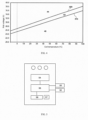
- FIG. 4 illustrates, as an example, the relationship between the pick voltages and coil temperatures.
- the rated voltage of the elevator brake is 48 volts, with temperature in degrees Celsius on the horizontal axis and pick voltage in volts on the vertical axis.
- an upper limit curve 400 and a lower limit curve 410 can be formed to represent the areas indicating that the brake state is normal and abnormal, as well as the warning area.
- the pick voltage falls in region 40, indicating that the brake state is normal; the pick voltage falls in area 42, indicating that the brake state is approaching abnormal; and the pick voltage falls in area 44, indicating that the current brake state is abnormal.
- the system 3 can be implemented in an electronic device separated from the elevator.
- the system 3 can determine the elevator brake state by electrically connecting the electronic device to the elevator brake.
- the system 3 can be implemented in, for example, a handheld portable electronic device, which is then electrically connected to the elevator system.
- the elevator system can be a brake subsystem of the elevator system, such as a terminal portion corresponding to the brake in the control cabinet, so as to determine the elevator brake state based on the pick voltage acquired, and the like. It can be seen that the inspection process of detecting the elevator brake no longer relies on manual gap detection to determine the brake state with using the system 3, thus saving manpower and various costs for elevator maintenance.
- FIG. 5 is a block diagram of an electronic device 5 for detecting the elevator brake state according to some examples of the present disclosure.
- the electronic device 5 includes a first connecting portion 50, a second connecting portion 52, a memory 54, and a processor 56.
- the electronic device 5 further includes a trigger button 57 and an output device 58.
- the power supply of the electronic device 5 can come from batteries or mains power supply.
- the second connecting portion 52 is used to obtain the pick voltage of the brake.
- the second connecting portion 52 may include a voltage acquisition component to acquire the pick voltage of the brake with the second connecting portion 52 connecting with the brake when the brake is in a picking process.
- the second connecting portion 52 can be configured as a signal receiving portion, which can be electrically connected to the elevator brake to receive signals indicating the magnitude of the pick voltage from the elevator brake, like the second connecting portion 52 receiving signals from the controller of the elevator brake.
- the electronic device 5 can be connected to the controller of the elevator through the first connecting portion 50 and the second connecting portion 52 to obtain the resistance and pick voltage of the brake.
- the first connecting portion 50 and the second connecting portion 52 can be connected to the corresponding interfaces of the elevator's control box to obtain the resistance and pick voltage.
- the electronic device 5 can further include an output device 58, which outputs signals generated by the processor 56.
- the output device 58 includes a communication interface and/or a display device. If the output device 58 is the communication interface, it can be used to transmit signals generated by the processor 56 from the electronic device 5 to other devices, such as computers, laptops, tablets, and smartphones that can inform the users of the signals.
- the display device above mentioned can be display screens, displays, audio output components, etc. arranged on the electronic device 5.
- the display device of the electronic device 5 can include three display lights, whose display colors are different from each other, so that the users can know which brake state is represented by the display light signal through the color. For example, when the pick voltage falls in an unsafe area, the red light is on, when the pick voltage falls in the early warning area, the yellow light is on, and when the pick voltage falls in a safe area, the green light is on.
- the electronic device 5 can also include a button 57.
- the button 57 When the button 57 is operated, the electronic device 5 is powered on to perform its function of detecting the brake.
- the button 57 can be a button in a trigger, press, voice controlled, or other form.
- the system for detecting the brake state of a conveying device according to the examples of the present disclosure can be arranged in the electronic device for detecting the brake state of a conveying device according to the examples of the present disclosure.
- the resistance detection component 30 is arranged at the first connecting portion 50
- the voltage acquisition component 32 is arranged at the second connecting portion 52
- the memory 34 and processor 36 can be respectively implemented in the memory 54 and processor 56.
- the electronic device 5 according to the examples of the present disclosure can be implemented as a portable electronic device, such as a handheld terminal, or in some possible cases, it can be implemented in a handheld terminal such as a mobile phone, a tablet, and so on.
- the first and second connecting portions of the electronic device 5 are connected to the elevator control cabinet to obtain the elevator brake temperature and pick voltage, respectively, and the obtained pick voltage is compared with the predetermined upper voltage threshold and lower voltage threshold corresponding to the obtained temperature to determine the brake state based on the pick voltage, with an indicator signal issued according to the state.
- a table of the relationship between coil temperature and pick voltage has been pre-stored in the electronic device 5.
- the pick voltage obtained at a temperature is compared with the upper voltage threshold and lower voltage threshold which were predetermined corresponding to that temperature. Accordingly, on the basis of the calculated temperature, the area for example shown by FIG.4 where the obtained pick voltage locates according to the relationship table can be determined.
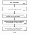
- FIG. 6 illustrates the flowchart of the method.
- the resistance of the brake is obtained.
- the resistance of the brake is detected through a resistance detection circuit or component.
- the pick voltage of the brake is obtained.
- the pick voltage is acquired through a voltage acquisition circuit.
- the temperature of the brake is calculated based on the resistance of the brake obtained and the initial resistance of the brake.
- the state of the brake is determined based on the calculated temperature and the obtained pick voltage.
- a signal indicating that the brake state is abnormal is generated when it is determined that the brake is in an abnormal state.
- the pick voltage is compared with the upper voltage threshold and the lower voltage threshold.
- FIG. 7 illustrates the process based on these examples.
- step S706 based on the calculated temperature, the acquired pick voltage is compared with the upper voltage threshold. If the acquired pick voltage is greater than the upper voltage threshold, it is determined that the brake state is abnormal, and proceeds to step S708.
- step S708 the signal indicating that the brake is abnormal is generated. If the acquired pick voltage is less than the upper voltage threshold, further compare it with the lower voltage threshold, as shown in step S709. If the acquired pick voltage is greater than the lower voltage threshold, a warning signal is generated, as shown in step S710. If the acquired pick voltage is less than the lower voltage threshold, a signal indicating that the brake state is normal can be generated, as shown in step S711, or no signal can be generated.
- the various examples of the method for detecting the elevator brake state described in combination with FIGS. 6 and 7 can be implemented by the various examples of the system 3 described above in conjunction with FIG. 3 , or by the various examples of the electronic device 5 described above in conjunction with FIG. 5 .
- the present disclosure further provides a non-transitory storage medium for storing program instructions, where the example described above can be implemented when the instructions stored in the storage medium are executed.
- the processor in the respective examples of the present disclosure may be, but is not limited to, a single-processor or multi-processor system of any of a wide array of possible architectures, including field programmable gate array (FPGA), central processing unit (CPU), application specific integrated circuits (ASIC), digital signal processor (DSP) or graphics processing unit (GPU) hardware arranged homogenously or heterogeneously.
- the memory may be but is not limited to a random access memory (RAM), read only memory (ROM), or other electronic, optical, magnetic or any other computer readable medium.
Landscapes
- Physics & Mathematics (AREA)
- Chemical & Material Sciences (AREA)
- General Physics & Mathematics (AREA)
- Health & Medical Sciences (AREA)
- Analytical Chemistry (AREA)
- Pathology (AREA)
- Chemical Kinetics & Catalysis (AREA)
- Electrochemistry (AREA)
- Immunology (AREA)
- Life Sciences & Earth Sciences (AREA)
- General Health & Medical Sciences (AREA)
- Biochemistry (AREA)
- Engineering & Computer Science (AREA)
- General Engineering & Computer Science (AREA)
- Mechanical Engineering (AREA)
- Braking Arrangements (AREA)
- Valves And Accessory Devices For Braking Systems (AREA)
- Maintenance And Inspection Apparatuses For Elevators (AREA)
Abstract
Description
- The present disclosure relates to technologies related to conveying devices, in particular to technologies for detecting the brake state of a conveying device.
- Elevators are used to transport passengers and/or goods. Passenger safety is one of the most important factors for elevators, and it is essential to prevent the elevator car from freely falling or moving up or down uncontrollably. Therefore, most countries have issued relevant regulations for elevator safety to ensure that elevators can be maintained regularly and operated safely. For example, it is required that the minimum release voltage of the brake should be less than 80% of the rated voltage. For another example, it is required that brake wear should be regularly inspected. Currently, maintenance and inspection of elevators are mainly carried out manually on-site, such as workers manually inspecting the wear of brake pads on site. It is necessary to make improvements in the maintenance of elevators.
- The present invention provides a system for detecting a brake state of a conveying device. The system may comprise a resistance detection component for detecting a resistance of the brake; a voltage acquisition component for acquiring a pick voltage of the brake; a memory for storing instructions; and a processor configured to execute the instructions. When executing the instructions, the processor can calculate the temperature of the brake based on the initial resistance of the brake and the resistance of the brake detected by the resistance detection circuit; determine the brake state from the calculated temperature and the pick voltage acquired by the voltage acquisition component; and generate a signal indicating an abnormal state when it is determined that the brake is in an abnormal state.
- Particular embodiments further may include at least one, or a plurality of, the following optional features, alone or in combination with each other:
- In the system for detecting a brake state of a conveying device, optionally, the processor, when executing the instructions, determines the brake state from the calculated temperature and the pick voltage acquired by the voltage acquisition component by performing the following operations: comparing the pick voltage with an upper voltage threshold based on the temperature calculated; and determining the brake state to be abnormal when the pick voltage is greater than the upper voltage threshold.
- In the system for detecting a brake state of a conveying device, optionally, the processor, when executing the instructions, further compares the pick voltage with a lower voltage threshold; generates a warning signal when the pick voltage is less than the upper voltage threshold but greater than the lower voltage threshold; and generates a signal indicating that the brake state is normal or not generates a signal when the pick voltage is less than the lower voltage threshold.
- In the system for detecting a brake state of a conveying device, optionally, an output device is further included.
- According to another aspect of the present disclosure, an electronic device for detecting a brake state of a conveying device is also provided. The electronic device may comprise a first connecting portion for obtaining a resistance of the brake; a second connecting portion for obtaining a pick voltage of the brake; a memory for storing instructions; and a processor configured to execute the instructions. When executing the instructions, the processor can calculate the temperature of the brake based on the initial resistance of the brake and the obtained resistance of the brake; determine the brake state from the calculated temperature and the obtained pick voltage; and generate a signal indicating an abnormal state when it is determined that the brake is in an abnormal state.
- Particular embodiments further may include at least one, or a plurality of, the following optional features, alone or in combination with each other:
- In the electronic device, optionally, the processor, when executing the instructions, determines the brake state from the temperature calculated and the pick voltage acquired by the voltage acquisition component by performing the following operations: comparing the pick voltage with an upper voltage threshold based on the temperature calculated; and determining the brake state to be abnormal when the pick voltage is greater than the upper voltage threshold.
- In the electronic device, optionally, the processor, when executing the instructions, can further compare the pick voltage with a lower voltage threshold; generates a warning signal when the pick voltage is less than the upper voltage threshold but greater than the lower voltage threshold; and generates a signal indicating that the brake state is normal or not generates a signal when the pick voltage is less than the lower voltage threshold.
- In the electronic device, optionally, the first connecting portion may comprise one of a signal receiving portion and a resistance detection component.
- In the electronic device, optionally, the second connecting portion may comprise one of a signal receiving portion and a voltage acquisition component.
- In the electronic device, optionally, the system may further comprise an output device comprising one or two of a display module and a communication module, wherein the display module may comprise one or more of a display screen, an indicator light, and a voice output device.
- According to yet another aspect of the present disclosure, a method for detecting a brake state of a conveying device is further provided. The method may comprise: obtaining a resistance of the brake; obtaining a pick voltage of the brake; calculating the temperature of the brake based on the initial resistance of the brake and the resistance of the brake obtained; determining the brake state from the temperature calculated and the pick voltage obtained; and generating a signal indicating the state when it is determined that the brake is in an abnormal state.
- Particular embodiments further may include at least one, or a plurality of, the following optional features, alone or in combination with each other:
- A non-transitory storage medium is still further provided for storing program instructions, where any one of the methods herein is implemented when the program instructions are executed.
- The present disclosure can be fully understood by referring to the detailed description of the specific embodiments below in conjunction with the accompanying drawings, where:
-
FIG. 1 briefly illustrates the structure of an elevator brake; -
FIG. 2 illustrates the variation curve of the pick voltage with the variation of the gap; -
FIG. 3 is a structural schematic diagram of a system 3 for detecting the elevator brake state according to an example of the present disclosure; -
FIG. 4 illustrates preset areas according to some examples of the present disclosure; -
FIG. 5 is a structural schematic diagram of an electronic device 5 for detecting the elevator brake state according to some examples of the present disclosure; -
FIG. 6 illustrates the flowchart of a method for detecting the elevator brake state; and -
FIG. 7 illustrates an implementation process of step S606 illustrated inFIG. 6 . - To assist those skilled in the art in accurately understanding the subject matter claimed in the present disclosure, the specific embodiments of the present disclosure will be described in detail below in conjunction with the accompanying drawings.
- The terms "first", "second", etc. in the description, claims, and accompanying drawings of the present disclosure are used to distinguish similar objects, rather than to describe a specific order or sequence thereof. It should be appreciated that the terms used in this way can be interchanged with each other in appropriate cases, so that the embodiments described herein can be implemented in orders other than those illustrated or described in the embodiments herein. In addition, "first" and "second" are only used for descriptive purposes, and cannot be understood as indicating or implying relative importance or implying or indicating the quantity of technical features indicated. Therefore, the features defined with "first" and "second" can explicitly or implicitly include one or more of such features. In the depiction of the embodiments of the present disclosure, unless otherwise stated, "a plurality of" means two or more.
- The terms "example", "as an example", or "illustratively", used in the following text mean "used as an example, embodiment, or illustration". Any embodiment depicted as an "example", or "as an example" or "illustratively" need not be interpreted as being superior or better than other embodiments.
- The term "conveying device" in the present disclosure includes devices used for transporting passengers and/or goods, such as elevators. The brake of the conveying device brakes the conveying device in its closed state to stop the conveying device from running. When the brake switches from the closed state to the open state, it releases the braking on the conveying device. The following embodiments of the present disclosure will use an elevator as an example of the conveying device, and accordingly, the elevator brake will be used as the conveying device brake for explanation.
- In the present disclosure, brake resistance and brake temperature refer to the resistance of the brake coil and the temperature of the brake coil, illustratively rather than restrictively.
-
FIG. 1 briefly illustrates the structure of an elevator brake. As shown inFIG. 1 , the brake comprises abrake component 11, anelastic component 15 such as a spring, astatic plate 17, and a drive circuit (not shown). Thebrake component 11 includes abrake lining plate 12 and anarmature plate 14 combined together, in which thebrake lining plate 12 is arranged on the side facing the component to be braked, and thearmature plate 14 is arranged on the side facing thestatic plate 17. The drive circuit includes acoil 160. It should be noted that the names of the various components of the brake described herein may differ in practical applications due to various factors such as the application environment. For example, thearmature plate 14 may be called an iron plate, a movable plate, etc., thebrake lining plate 12 may be called a brake shoe, a brake lining, etc., and thebrake wheel 10 may also be called a rope wheel, a brake drum, and the like. It should be appreciated that compared to the structure illustrated here, the brake actually includes more components. The illustration of the brake in the present disclosure is only intended to illustrate its principles and working process related to the present disclosure in a concise and direct manner, and is not intended to illustrate or restrict the specific structure and shape of the brake. - Voltage is applied to the
coil 160 to make it energized. As the voltage increases, the magnetic field generated by thecoil 160 increases. The force of the magnetic field causes thearmature plate 14 to overcome the force of theelastic component 15 and move away from thebrake wheel 10, thereby releasing the braking. The voltage, which is applied to thecoil 160 to change the brake component from a closed state to an open state so as to release braking, is called the opening voltage, also known as the release or pick voltage. When the electric power applied to thecoil 160 is cut off, the electromagnetic force acting on thearmature plate 14 disappears. Under the action of thespring 15, thearmature plate 14 moves towards the direction of thebrake wheel 10, causing thebrake lining plate 12 of the brake component to press against thebrake wheel 10, thereby achieving the braking of thebrake wheel 10 through the friction force between thebrake lining plate 12 and thebrake wheel 10. With the use of the elevator, thebrake lining plate 12 gradually wears out due to friction with thebrake wheel 10, causing the gap between thebrake lining plate 12 and thebrake wheel 10 to increase, which leads to an increase in the pick voltage. -
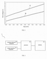
FIG. 2 illustrates the variation curve of the pick voltage with the variation of the gap, where the horizontal axis represents the gap in millimeter and the vertical axis represents the pick voltage Vpick in volt.Curve 20 is the relation curve between the pick voltage Vpick and the gap when the brake is at 20 degrees Celsius, andcurve 22 is the relation curve between the pick voltage and the gap when the brake is at 100 degrees Celsius. -
FIG. 3 is a block diagram of a system 3 for detecting the elevator brake state according to some examples of the present disclosure. As shown inFIG. 3 , the system 3 includes aresistance detection component 30, avoltage acquisition component 32, amemory 34, and aprocessor 36. Theresistance detection component 30 is used to detect the resistance of the brake. Thevoltage acquisition component 32 is used to acquire the pick voltage of the brake. Thememory 34 stores program instructions. Theprocessor 36 is configured to execute the instructions and, when executing the instructions, calculate the temperature of the brake based on the brake resistance detected by theresistance detection component 30 and the initial resistance of the brake; determine the brake state from the temperature calculated and the pick voltage acquired; and, generate a signal indicating an abnormal state when it is determined that the brake state is abnormal. - In an embodiment of the present disclosure, by way of example, the resistance of the brake coil is used as the resistance of the brake, such as the
coil 160 inFIG. 1 . The rising and falling of the temperature of the coil affect its own resistance. Therefore, the brake temperature can be determined based on the resistance detected by theresistance detection component 30. It should be noted that in the various examples of the present disclosure, the coil temperature is used as the brake temperature, illustratively rather than restrictively. - The
resistance detection component 30 can be a resistance detection circuit, or other component or means that can detect resistance. For example, theresistance detection component 30 may be a signal receiver in some cases, which receives signals indicating the magnitude of the brake resistance transmitted by the elevator controller or brake controller. - The
voltage acquisition component 32 is used to acquire the pick voltage of the brake, which can be implemented as a circuit or, if possible, a voltage sensor. Taking the brake inFIG. 1 as an example, as the voltage applied to thecoil 160 increases, thebrake component 11 moves away frombrake wheel 10 towards thestatic plate 17. During the movement of thebrake component 11, the switch arranged on the brake will be triggered. According to the example of the present disclosure, thevoltage acquisition component 32 is configured to acquire the voltage of thecoil 160 as the pick voltage when the switch is triggered. For example, thevoltage acquisition component 32 can be connected to the switch of the brake to acquire the voltage when the switch is triggered. - As an alternative, the
voltage acquisition component 32 can also be implemented as a signal receiver for receiving signals indicating the magnitude of the pick voltage when the switch is triggered transmitted by the elevator controller or brake controller. The implementation of thevoltage acquisition component 32 is not limited to the depiction here, as long as it can enable the system 3 to obtain the pick voltage. - In addition, the switch, namely the switch arranged on the brake to be triggered as mentioned above, can be an existing switch disposed on the brake that can be triggered during the pick process, or can be a switch configured additionally to be triggered. It should be noted that although the various embodiments of the present disclosure use the voltage when the switch is triggered as the value of the pick voltage, the voltage at other times during the pick process is also feasible.
- For example, the relationship between the temperature and resistance of the coil in this example can be represented by formula (1):

resistance detection component 30, Rinitial is the initial resistance of the coil, tT is the brake temperature when theresistance detection component 30 detects the resistance RT, and tinitial is the brake temperature at the initial resistance. - The initial resistance of the coil is a resistance value that is predetermined and stored in the system 3, such as the resistance value stored in the
memory 34. When theprocessor 36 executes instructions in thememory 34, it obtains the resistance value of the initial resistance from thememory 34 and calculates the temperature tT according to formula (1). It should be noted that the initial resistance of the coil can be, for example, the resistance value of the coil at 20 degrees Celsius. - For coils, the pick voltage increases as the gap increases at the same temperature. According to the examples of the present disclosure, the relationship between a temperatures and a pick voltage can be predetermined. In other words, for each temperature, the upper voltage threshold at that temperature can be predetermined. In the embodiments of the present disclosure, for the same temperature, an upper voltage threshold for that temperature is predetermined, and a lower voltage threshold for that temperature is also determined. If the pick voltage is greater than the upper voltage threshold for the temperature, it indicates that the brake is abnormal. If the pick voltage is between the upper voltage threshold and the lower voltage threshold, it indicates that it is highly possible that the brake has entered an abnormal state or is about to enter an abnormal state. If the pick voltage is less than the lower voltage threshold, it indicates that the brake is normal. In some examples, when the brake is abnormal, a signal indicating that the brake is abnormal is issued, and when the brake is about to enter an abnormal state, a warning signal indicating an early warning is issued.
- According to the examples of the present disclosure, the
processor 36 compares the pick voltage with the upper voltage threshold based on the calculated temperature. That is to say, for the calculated temperature, the acquired pick voltage at that temperature is compared with the upper and lower voltage thresholds for that temperature. When the pick voltage is greater than the upper voltage threshold, theprocessor 36 generates a signal indicating that the brake state is abnormal. When the pick voltage is less than the upper voltage threshold but greater than the lower voltage threshold, theprocessor 36 generates a warning signal. When the pick voltage is less than the lower voltage threshold, theprocessor 36 may not process or may generate a signal indicating that the brake is normal. - For example, for temperature tT, the upper voltage threshold and lower voltage threshold can be determined by the following formulas (2) and (3):


- K is calculated according to the following formula (4):

resistance detection component 30, tT is the brake temperature when theresistance detection component 30 detects the resistance RT, Rlimited is a set resistance value that can be set according to relevant specifications and standards for elevator brake temperature, such as 110 degrees. tlimited is the temperature of the coil when the resistance value is Rlimited. - The relationship between coil temperatures and pick voltages can be predetermined, thus forming a table of the relationship between the temperatures and the voltages.
FIG. 4 illustrates, as an example, the relationship between the pick voltages and coil temperatures. In this example, the rated voltage of the elevator brake is 48 volts, with temperature in degrees Celsius on the horizontal axis and pick voltage in volts on the vertical axis. For the upper voltage threshold and lower voltage threshold set for each temperature, anupper limit curve 400 and alower limit curve 410 can be formed to represent the areas indicating that the brake state is normal and abnormal, as well as the warning area. As shown inFIG. 4 , the pick voltage falls inregion 40, indicating that the brake state is normal; the pick voltage falls inarea 42, indicating that the brake state is approaching abnormal; and the pick voltage falls inarea 44, indicating that the current brake state is abnormal. - The system 3 for detecting the elevator brake state can be implemented in existing equipment, such as in a control cabinet of an elevator control system. In this case, a function key can be configured for the system 3, so that maintenance personnel can be informed to operate the function key to make the system 3 work during elevator maintenance, thereby detecting the elevator brake state. For example, when the elevator is not carrying passengers, or during maintenance, maintenance personnel press the function key to detect the current resistance of the brake and calculate the current temperature of the brake according to formula (1). On the other hand, the brake is switched from a closed state to an open state (i.e., pick) to obtain the pick voltage, and the brake state is determined based on the temperature and pick voltage. Upon determining the state, the controller outputs a signal indicating the state for maintenance personnel to get to know the brake state.
- As an alternative, the system 3 can be implemented in an electronic device separated from the elevator. The system 3 can determine the elevator brake state by electrically connecting the electronic device to the elevator brake. For example, the system 3 can be implemented in, for example, a handheld portable electronic device, which is then electrically connected to the elevator system. As an example, the elevator system can be a brake subsystem of the elevator system, such as a terminal portion corresponding to the brake in the control cabinet, so as to determine the elevator brake state based on the pick voltage acquired, and the like. It can be seen that the inspection process of detecting the elevator brake no longer relies on manual gap detection to determine the brake state with using the system 3, thus saving manpower and various costs for elevator maintenance.
-
FIG. 5 is a block diagram of an electronic device 5 for detecting the elevator brake state according to some examples of the present disclosure. As shown in the figure, the electronic device 5 includes a first connectingportion 50, a second connectingportion 52, amemory 54, and aprocessor 56. Optionally, the electronic device 5 further includes atrigger button 57 and anoutput device 58. The power supply of the electronic device 5 can come from batteries or mains power supply. - The first connecting
portion 50 is used to obtain the resistance of the elevator brake. In some examples, the first connectingportion 50 may be connected to the corresponding interface of the elevator brake, and the resistance of the elevator brake is detected by a resistance detection component arranged in the first connectingportion 50. In some examples, the first connectingportion 50 is configured as a signal receiving portion, which can be electrically connected to the elevator brake to receive signals indicating the magnitude of the resistance of the elevator brake from the elevator brake, like the first connecting portion 51 receiving signals from the controller of the elevator brake. - The second connecting
portion 52 is used to obtain the pick voltage of the brake. In some examples, the second connectingportion 52 may include a voltage acquisition component to acquire the pick voltage of the brake with the second connectingportion 52 connecting with the brake when the brake is in a picking process. In other examples, the second connectingportion 52 can be configured as a signal receiving portion, which can be electrically connected to the elevator brake to receive signals indicating the magnitude of the pick voltage from the elevator brake, like the second connectingportion 52 receiving signals from the controller of the elevator brake. - The signal receiving portion may receive signals through line connection in the present disclosure. However, it is also possible to receive signals through wireless communication.
- In addition, according to some embodiments of the present disclosure, the electronic device 5 can be connected to the controller of the elevator through the first connecting
portion 50 and the second connectingportion 52 to obtain the resistance and pick voltage of the brake. In some specific examples, the first connectingportion 50 and the second connectingportion 52 can be connected to the corresponding interfaces of the elevator's control box to obtain the resistance and pick voltage. - Instructions are stored in the
memory 54. Theprocessor 56 is configured to execute these instructions and, when executing these instructions, calculate the temperature tT according to formula (1), and determine, based on the temperature calculated, whether the pick voltage acquired is located in thearea 40 representing that the brake is normal, or in thearea 44 representing that the brake is abnormal, or in theearly warning area 42 representing that the brake is approaching abnormal, as shown inFIG. 4 - Specifically, for the calculated temperature tT, the acquired pick voltage is compared with the upper voltage threshold and lower voltage threshold for temperature tr. When the pick voltage is greater than the upper voltage threshold, the
processor 56 generates a signal indicating that the brake state is abnormal. When the pick voltage is less than the upper voltage threshold but greater than the lower voltage threshold, theprocessor 56 generates a warning signal. When the pick voltage is less than the lower voltage threshold, theprocessor 56 may take no action or may generate a signal indicating that the brake is normal. - According to some examples of the present disclosure, the electronic device 5 can further include an
output device 58, which outputs signals generated by theprocessor 56. Theoutput device 58 includes a communication interface and/or a display device. If theoutput device 58 is the communication interface, it can be used to transmit signals generated by theprocessor 56 from the electronic device 5 to other devices, such as computers, laptops, tablets, and smartphones that can inform the users of the signals. The display device above mentioned can be display screens, displays, audio output components, etc. arranged on the electronic device 5. According to a specific example of the present disclosure, the display device of the electronic device 5 can include three display lights, whose display colors are different from each other, so that the users can know which brake state is represented by the display light signal through the color. For example, when the pick voltage falls in an unsafe area, the red light is on, when the pick voltage falls in the early warning area, the yellow light is on, and when the pick voltage falls in a safe area, the green light is on. - According to some examples of the present disclosure, the electronic device 5 can also include a
button 57. When thebutton 57 is operated, the electronic device 5 is powered on to perform its function of detecting the brake. Thebutton 57 can be a button in a trigger, press, voice controlled, or other form. - The system for detecting the brake state of a conveying device according to the examples of the present disclosure can be arranged in the electronic device for detecting the brake state of a conveying device according to the examples of the present disclosure. At the same time, in conjunction with
FIGS. 3 and4 , theresistance detection component 30 is arranged at the first connectingportion 50, thevoltage acquisition component 32 is arranged at the second connectingportion 52, and thememory 34 andprocessor 36 can be respectively implemented in thememory 54 andprocessor 56. The electronic device 5 according to the examples of the present disclosure can be implemented as a portable electronic device, such as a handheld terminal, or in some possible cases, it can be implemented in a handheld terminal such as a mobile phone, a tablet, and so on. - The first and second connecting portions of the electronic device 5 according to the present disclosure are connected to the elevator control cabinet to obtain the elevator brake temperature and pick voltage, respectively, and the obtained pick voltage is compared with the predetermined upper voltage threshold and lower voltage threshold corresponding to the obtained temperature to determine the brake state based on the pick voltage, with an indicator signal issued according to the state. Generally speaking, a table of the relationship between coil temperature and pick voltage has been pre-stored in the electronic device 5. The pick voltage obtained at a temperature is compared with the upper voltage threshold and lower voltage threshold which were predetermined corresponding to that temperature. Accordingly, on the basis of the calculated temperature, the area for example shown by
FIG.4 where the obtained pick voltage locates according to the relationship table can be determined. - The present disclosure also provides a method for detecting the elevator brake state.
FIG. 6 illustrates the flowchart of the method. As shown inFIG. 6 , in step S600, the resistance of the brake is obtained. For example, the resistance of the brake is detected through a resistance detection circuit or component. In step S602, the pick voltage of the brake is obtained. For example, the pick voltage is acquired through a voltage acquisition circuit. In step S604, the temperature of the brake is calculated based on the resistance of the brake obtained and the initial resistance of the brake. In step S606, the state of the brake is determined based on the calculated temperature and the obtained pick voltage. In step S608, a signal indicating that the brake state is abnormal is generated when it is determined that the brake is in an abnormal state. - According to some examples of the present disclosure, the pick voltage is compared with the upper voltage threshold and the lower voltage threshold.
FIG. 7 illustrates the process based on these examples. As shown inFIG. 7 , in step S706, based on the calculated temperature, the acquired pick voltage is compared with the upper voltage threshold. If the acquired pick voltage is greater than the upper voltage threshold, it is determined that the brake state is abnormal, and proceeds to step S708. In step S708, the signal indicating that the brake is abnormal is generated. If the acquired pick voltage is less than the upper voltage threshold, further compare it with the lower voltage threshold, as shown in step S709. If the acquired pick voltage is greater than the lower voltage threshold, a warning signal is generated, as shown in step S710. If the acquired pick voltage is less than the lower voltage threshold, a signal indicating that the brake state is normal can be generated, as shown in step S711, or no signal can be generated. - The various examples of the method for detecting the elevator brake state described in combination with
FIGS. 6 and7 can be implemented by the various examples of the system 3 described above in conjunction withFIG. 3 , or by the various examples of the electronic device 5 described above in conjunction withFIG. 5 . - In practical applications, the various examples of the method for detecting the elevator brake state described in conjunction with
FIGS. 6 and7 can be implemented as one or more programs through program instructions, implemented by a device with a processor and, if necessary, also two interfaces to be connected with the elevator controller. - The present disclosure further provides a non-transitory storage medium for storing program instructions, where the example described above can be implemented when the instructions stored in the storage medium are executed.
- The above examples in the present disclosure are all described using elevator brakes as specific examples. However, the systems, electronic devices, and methods of the above examples can also be applied to conveying devices such as escalators.
- The processor in the respective examples of the present disclosure may be, but is not limited to, a single-processor or multi-processor system of any of a wide array of possible architectures, including field programmable gate array (FPGA), central processing unit (CPU), application specific integrated circuits (ASIC), digital signal processor (DSP) or graphics processing unit (GPU) hardware arranged homogenously or heterogeneously. The memory may be but is not limited to a random access memory (RAM), read only memory (ROM), or other electronic, optical, magnetic or any other computer readable medium.
- Although specific embodiments of the present disclosure have been shown and described in detail to illustrate the principles of the present disclosure, it should be understood, however, that the features of the respective embodiments and examples of the present disclosure are illustrative rather than restrictive. That is, they can be implemented in other ways without departing from the principles of the present disclosure, including new embodiments formed by the combination of features between the respective embodiments and examples.
Claims (15)
- A system for detecting a state of a brake of a conveying device, comprising:a resistance detection component for detecting a resistance of the brake;a voltage acquisition component for acquiring a pick voltage of the brake;a memory for storing instructions; anda processor for executing the instructions for:calculating a temperature of the brake based on an initial resistance of the brake and the detected resistance;determining the state of the brake from the calculated temperature and the acquired pick voltage; andgenerating a signal indicating that the state is abnormal when it is determined that the brake is in an abnormal state.
- The system according to claim 1, wherein the processor, when executing the instructions, determines the state of the brake from the calculated temperature and the acquired pick voltage by performing following operations:comparing the pick voltage with an upper voltage threshold based on the calculated temperature; anddetermining the state of the brake to be abnormal when the pick voltage is greater than the upper voltage threshold.
- The system according to claim 2, wherein the processor, when executing the instructions, further:compares the pick voltage with a lower voltage threshold;generates a warning signal when the pick voltage is less than the upper voltage threshold but greater than the lower voltage threshold; andgenerates a signal indicating that the state of the brake is normal or not generates a signal, when the pick voltage is less than the lower voltage threshold.
- The system according to any of claims 1-3, wherein the system further comprises an output device, where the output device comprises one or two of a display module and a communication module, and the display module comprises one or more of a display screen, an indicator light, and a voice output device.
- An electronic device for detecting a state of a brake of a conveying device, the electronic device configured for use in the system according to any of claims 1 - 4 and comprising:a first connecting portion for obtaining a resistance of the brake;a second connecting portion for obtaining a pick voltage of the brake;a memory for storing instructions; anda processor configured for executing the instructions for:calculating a temperature of the brake based on an initial resistance of the brake and the obtained resistance;determining the state of the brake from the calculated temperature and the obtained pick voltage; andgenerating a signal indicating that the state is abnormal when it is determined that the brake is in an abnormal state.
- The electronic device according to claim 5, wherein the processor, when executing the instructions, determines the state of the brake from the calculated temperature and the obtained pick voltage by performing following operations:comparing the pick voltage with an upper voltage threshold based on the calculated temperature; anddetermining the state of the brake to be abnormal when the pick voltage is greater than the upper voltage threshold;wherein particularly the processor, when executing the instructions, further:compares the pick voltage with a lower voltage threshold;generates a warning signal when the pick voltage is less than the upper voltage threshold but greater than the lower voltage threshold; andgenerates a signal indicating that the state of the brake is normal or not generates a signal, when the pick voltage is less than the lower voltage threshold.
- The electronic device according to claim 5 or 6, wherein the first connecting portion comprises one of a signal receiving portion and a resistance detection component.
- The electronic device according to any of claims 5-7, wherein the second connecting portion comprises one of a signal receiving portion and a voltage acquisition component.
- The electronic device according to any of claims 5-8, wherein the system further comprises an output device comprising one or two of a display module and a communication module, where the display module comprises one or more of a display screen, an indicator light, and a voice output device.
- A method for detecting a state of a brake of a conveying device, comprising:obtaining a resistance of the brake;obtaining a pick voltage of the brake;calculating a temperature of the brake based on an initial resistance of the brake and the obtained resistance;determining the state of the brake from the calculated temperature and the obtained pick voltage; andgenerating a signal indicating the state when it is determined that the brake is in an abnormal state.
- The method according to claim 10, wherein determining the state of the brake from the calculated temperature and the obtained pick voltage, comprising:comparing the pick voltage with an upper voltage threshold based on the temperature calculated;determining the state of the brake to be abnormal when the pick voltage is greater than the upper voltage threshold.
- The method according to claim 11, further comprising:comparing the pick voltage with a lower voltage threshold;generating a warning signal when the pick voltage is less than the upper voltage threshold but greater than the lower voltage threshold; andgenerating a signal indicating that the state of the brake is normal or not generating a signal, when the pick voltage is less than the lower voltage threshold.
- The method according to any of claims 10-12, further comprising outputting the generated signal indicating the state of the brake.
- The system according to any of claims 1-4, the electronic device according to any of claims 5-9, and the method according to any of claims 10-13, wherein the conveying device is an elevator.
- A non-transitory storage medium for storing program instructions, wherein the method according to any of claims 10-13 is implemented when the program instructions are executed.
Applications Claiming Priority (1)
| Application Number | Priority Date | Filing Date | Title |
|---|---|---|---|
| CN202311172637.4A CN119612304A (en) | 2023-09-12 | 2023-09-12 | System, electronic device and method for detecting conveyor brake status |
Publications (2)
| Publication Number | Publication Date |
|---|---|
| EP4534463A2 true EP4534463A2 (en) | 2025-04-09 |
| EP4534463A3 EP4534463A3 (en) | 2025-06-18 |
Family
ID=92708325
Family Applications (1)
| Application Number | Title | Priority Date | Filing Date |
|---|---|---|---|
| EP24198737.9A Pending EP4534463A3 (en) | 2023-09-12 | 2024-09-05 | System and method for detecting a status of a brake of a conveyor device |
Country Status (3)
| Country | Link |
|---|---|
| US (1) | US20250083901A1 (en) |
| EP (1) | EP4534463A3 (en) |
| CN (1) | CN119612304A (en) |
Families Citing this family (1)
| Publication number | Priority date | Publication date | Assignee | Title |
|---|---|---|---|---|
| US12565401B2 (en) * | 2021-02-01 | 2026-03-03 | Otis Elevator Company | Elevator switch monitoring device |
Family Cites Families (4)
| Publication number | Priority date | Publication date | Assignee | Title |
|---|---|---|---|---|
| JP2005027454A (en) * | 2003-07-04 | 2005-01-27 | Mitsubishi Electric Corp | Vehicle control device |
| JP6603483B2 (en) * | 2015-05-28 | 2019-11-06 | 株式会社日立ビルシステム | Abnormality detection apparatus and abnormality detection method |
| CN109292573B (en) * | 2018-11-30 | 2020-12-22 | 日立楼宇技术(广州)有限公司 | Brake coil detection method, device, equipment and storage medium |
| US20210101782A1 (en) * | 2019-10-04 | 2021-04-08 | Otis Elevator Company | Electromagnetic brake temperature monitoring system and method |
-
2023
- 2023-09-12 CN CN202311172637.4A patent/CN119612304A/en active Pending
-
2024
- 2024-09-05 EP EP24198737.9A patent/EP4534463A3/en active Pending
- 2024-09-11 US US18/882,170 patent/US20250083901A1/en active Pending
Also Published As
| Publication number | Publication date |
|---|---|
| US20250083901A1 (en) | 2025-03-13 |
| CN119612304A (en) | 2025-03-14 |
| EP4534463A3 (en) | 2025-06-18 |
Similar Documents
| Publication | Publication Date | Title |
|---|---|---|
| US12319541B2 (en) | Image analytics for elevator maintenance | |
| KR102609384B1 (en) | Work area technician warning system | |
| CN103145015B (en) | The method of inspection of balance coefficient of elevator | |
| CN105800413A (en) | Elevator fault diagnosis device and method | |
| US20250083901A1 (en) | System, electric device and method for detecting a status of a brake of a conveyor device | |
| KR101988032B1 (en) | The safety support system for worker at railroad | |
| JP2015034076A (en) | Elevator system, elevator control device and elevator control method for the same | |
| CN106315373A (en) | Elevator landing door lock contact state detecting device and method | |
| KR101736328B1 (en) | safety monitoring system of crane using wireless communication network | |
| KR101602143B1 (en) | Crane safety monitoring system | |
| CN206872302U (en) | A kind of safety alarm device of workshop movement lifting appliance | |
| EP3053866B1 (en) | Elevator brake release monitoring | |
| JP6577928B2 (en) | Electric hoist and life management method of electromagnetic contactor mounted thereon | |
| CN202704745U (en) | Lift car unbalance loading automatic detector | |
| CN204649893U (en) | Built on stilts fault detector stationary installation | |
| JP6403470B2 (en) | Equipment management system | |
| CN204474071U (en) | An elevator fault detection system based on the Internet of Things | |
| CN103770702A (en) | Vehicle slipping detecting device and method | |
| CN203959721U (en) | For the device of steel wire rope jump prevention forewarn system | |
| CN223678627U (en) | Load weight digital display equipment and maintenance platform | |
| CN203713695U (en) | Vehicle sliding detection device | |
| CN116462071B (en) | Measuring hopper system and its usage | |
| CN223254675U (en) | Cage loading system | |
| CN203558670U (en) | Elevator safety protection device | |
| CN208898307U (en) | A kind of mounting structure of elevator load detection device |
Legal Events
| Date | Code | Title | Description |
|---|---|---|---|
| PUAI | Public reference made under article 153(3) epc to a published international application that has entered the european phase |
Free format text: ORIGINAL CODE: 0009012 |
|
| STAA | Information on the status of an ep patent application or granted ep patent |
Free format text: STATUS: THE APPLICATION HAS BEEN PUBLISHED |
|
| AK | Designated contracting states |
Kind code of ref document: A2 Designated state(s): AL AT BE BG CH CY CZ DE DK EE ES FI FR GB GR HR HU IE IS IT LI LT LU LV MC ME MK MT NL NO PL PT RO RS SE SI SK SM TR |
|
| PUAL | Search report despatched |
Free format text: ORIGINAL CODE: 0009013 |
|
| AK | Designated contracting states |
Kind code of ref document: A3 Designated state(s): AL AT BE BG CH CY CZ DE DK EE ES FI FR GB GR HR HU IE IS IT LI LT LU LV MC ME MK MT NL NO PL PT RO RS SE SI SK SM TR |
|
| RIC1 | Information provided on ipc code assigned before grant |
Ipc: B66B 5/00 20060101AFI20250513BHEP |
|
| STAA | Information on the status of an ep patent application or granted ep patent |
Free format text: STATUS: REQUEST FOR EXAMINATION WAS MADE |
|
| 17P | Request for examination filed |
Effective date: 20251117 |
|
| STAA | Information on the status of an ep patent application or granted ep patent |
Free format text: STATUS: EXAMINATION IS IN PROGRESS |
|
| 17Q | First examination report despatched |
Effective date: 20260303 |