EP4534427A1 - Machine for producing containers filled with a product and sealed - Google Patents
Machine for producing containers filled with a product and sealed Download PDFInfo
- Publication number
- EP4534427A1 EP4534427A1 EP24201975.0A EP24201975A EP4534427A1 EP 4534427 A1 EP4534427 A1 EP 4534427A1 EP 24201975 A EP24201975 A EP 24201975A EP 4534427 A1 EP4534427 A1 EP 4534427A1
- Authority
- EP
- European Patent Office
- Prior art keywords
- drying
- drying tunnel
- flow
- chamber
- sheet
- Prior art date
- Legal status (The legal status is an assumption and is not a legal conclusion. Google has not performed a legal analysis and makes no representation as to the accuracy of the status listed.)
- Withdrawn
Links
Images

Classifications
-
- B—PERFORMING OPERATIONS; TRANSPORTING
- B65—CONVEYING; PACKING; STORING; HANDLING THIN OR FILAMENTARY MATERIAL
- B65B—MACHINES, APPARATUS OR DEVICES FOR, OR METHODS OF, PACKAGING ARTICLES OR MATERIALS; UNPACKING
- B65B9/00—Enclosing successive articles, or quantities of material, e.g. liquids or semiliquids, in flat, folded, or tubular webs of flexible sheet material; Subdividing filled flexible tubes to form packages
- B65B9/10—Enclosing successive articles, or quantities of material, in preformed tubular webs, or in webs formed into tubes around filling nozzles, e.g. extruded tubular webs
-
- B—PERFORMING OPERATIONS; TRANSPORTING
- B65—CONVEYING; PACKING; STORING; HANDLING THIN OR FILAMENTARY MATERIAL
- B65B—MACHINES, APPARATUS OR DEVICES FOR, OR METHODS OF, PACKAGING ARTICLES OR MATERIALS; UNPACKING
- B65B31/00—Packaging articles or materials under special atmospheric or gaseous conditions; Adding propellants to aerosol containers
- B65B31/02—Filling, closing, or filling and closing, containers or wrappers in chambers maintained under vacuum or superatmospheric pressure or containing a special atmosphere, e.g. of inert gas
-
- B—PERFORMING OPERATIONS; TRANSPORTING
- B65—CONVEYING; PACKING; STORING; HANDLING THIN OR FILAMENTARY MATERIAL
- B65B—MACHINES, APPARATUS OR DEVICES FOR, OR METHODS OF, PACKAGING ARTICLES OR MATERIALS; UNPACKING
- B65B31/00—Packaging articles or materials under special atmospheric or gaseous conditions; Adding propellants to aerosol containers
- B65B31/04—Evacuating, pressurising or gasifying filled containers or wrappers by means of nozzles through which air or other gas, e.g. an inert gas, is withdrawn or supplied
- B65B31/044—Evacuating, pressurising or gasifying filled containers or wrappers by means of nozzles through which air or other gas, e.g. an inert gas, is withdrawn or supplied the nozzles being combined with a filling device
- B65B31/045—Evacuating, pressurising or gasifying filled containers or wrappers by means of nozzles through which air or other gas, e.g. an inert gas, is withdrawn or supplied the nozzles being combined with a filling device of Vertical Form-Fill-Seal [VFFS] machines
-
- B—PERFORMING OPERATIONS; TRANSPORTING
- B65—CONVEYING; PACKING; STORING; HANDLING THIN OR FILAMENTARY MATERIAL
- B65B—MACHINES, APPARATUS OR DEVICES FOR, OR METHODS OF, PACKAGING ARTICLES OR MATERIALS; UNPACKING
- B65B55/00—Preserving, protecting or purifying packages or package contents in association with packaging
- B65B55/02—Sterilising, e.g. of complete packages
- B65B55/025—Packaging in aseptic tunnels
-
- B—PERFORMING OPERATIONS; TRANSPORTING
- B65—CONVEYING; PACKING; STORING; HANDLING THIN OR FILAMENTARY MATERIAL
- B65B—MACHINES, APPARATUS OR DEVICES FOR, OR METHODS OF, PACKAGING ARTICLES OR MATERIALS; UNPACKING
- B65B55/00—Preserving, protecting or purifying packages or package contents in association with packaging
- B65B55/02—Sterilising, e.g. of complete packages
- B65B55/027—Packaging in aseptic chambers
-
- B—PERFORMING OPERATIONS; TRANSPORTING
- B65—CONVEYING; PACKING; STORING; HANDLING THIN OR FILAMENTARY MATERIAL
- B65B—MACHINES, APPARATUS OR DEVICES FOR, OR METHODS OF, PACKAGING ARTICLES OR MATERIALS; UNPACKING
- B65B55/00—Preserving, protecting or purifying packages or package contents in association with packaging
- B65B55/02—Sterilising, e.g. of complete packages
- B65B55/04—Sterilising wrappers or receptacles prior to, or during, packaging
- B65B55/10—Sterilising wrappers or receptacles prior to, or during, packaging by liquids or gases
- B65B55/103—Sterilising flat or tubular webs
-
- B—PERFORMING OPERATIONS; TRANSPORTING
- B65—CONVEYING; PACKING; STORING; HANDLING THIN OR FILAMENTARY MATERIAL
- B65B—MACHINES, APPARATUS OR DEVICES FOR, OR METHODS OF, PACKAGING ARTICLES OR MATERIALS; UNPACKING
- B65B9/00—Enclosing successive articles, or quantities of material, e.g. liquids or semiliquids, in flat, folded, or tubular webs of flexible sheet material; Subdividing filled flexible tubes to form packages
- B65B9/10—Enclosing successive articles, or quantities of material, in preformed tubular webs, or in webs formed into tubes around filling nozzles, e.g. extruded tubular webs
- B65B9/20—Enclosing successive articles, or quantities of material, in preformed tubular webs, or in webs formed into tubes around filling nozzles, e.g. extruded tubular webs the webs being formed into tubes in situ around the filling nozzles
- B65B9/207—Enclosing successive articles, or quantities of material, in preformed tubular webs, or in webs formed into tubes around filling nozzles, e.g. extruded tubular webs the webs being formed into tubes in situ around the filling nozzles the web advancing continuously
-
- B—PERFORMING OPERATIONS; TRANSPORTING
- B65—CONVEYING; PACKING; STORING; HANDLING THIN OR FILAMENTARY MATERIAL
- B65B—MACHINES, APPARATUS OR DEVICES FOR, OR METHODS OF, PACKAGING ARTICLES OR MATERIALS; UNPACKING
- B65B51/00—Devices for, or methods of, sealing or securing package folds or closures; Devices for gathering or twisting wrappers, or necks of bags
- B65B51/10—Applying or generating heat or pressure or combinations thereof
- B65B51/26—Devices specially adapted for producing transverse or longitudinal seams in webs or tubes
Definitions
- the present invention relates to a machine for producing containers filled with a product and sealed starting from a sheet of packaging material.
- the present invention regards a machine of the type comprising:
- the drying tunnel is traversed by a flow of air in a direction opposite to the direction of advance of the sheet, which performs the function of completing drying of the sheet before this reaches the forming chamber for production of the aforesaid containers.
- the purpose of drying the sheet is to remove the sterilizing liquid with which the two opposite faces of the sheet are set in contact so that they are sterilized prior to the aforesaid forming step.
- a first position is to be understood as being “upstream” of a second position when the aforesaid first position precedes the second position with reference to the direction of feed of the object; instead, the second position is to be understood as being “downstream” of the first position in so far as it follows the first position once again with reference to the direction of feed of the object.
- the present invention concerns a machine for producing containers filled with a product and sealed starting from a sheet of packaging material.
- the machine preferably comprises a system for feeding said sheet for making said sheet advance in a direction of advance along a processing path.
- the machine preferably comprises a drying chamber, set along said processing path and equipped with at least one drying device for drying said sheet that advances along said processing path.
- the machine preferably comprises a forming chamber, in which said sheet is formed so as to obtain said containers and which is set downstream of said drying chamber along said processing path.
- the machine preferably comprises a drying tunnel that extends along said processing path and sets said drying chamber and said forming chamber in fluid communication with one another.
- the machine preferably comprises an air-supply system connected to said forming chamber for supplying a flow of air from said forming chamber to said drying chamber, through said drying tunnel; preferably, within said drying tunnel said flow of air is in a direction opposite to the direction of advance of the sheet.
- said drying tunnel includes an inlet via which said flow of air enters the drying tunnel, and an outlet via which said flow of air exits from the drying tunnel.
- said drying tunnel has a portion that has a cross section decreasing from the forming chamber to the drying chamber and includes the inlet of the drying tunnel.
- the machine is able to carry out effective drying of the sheet of packaging material. Moreover, the drawback discussed above regarding the risk of a loss of sterility of the forming chamber is eliminated.
- the present invention concerns a method for producing containers filled with a product and sealed starting from a sheet of packaging material.
- the method preferably comprises the step of feeding said sheet in a direction of advance along a processing path.
- the method preferably comprises the step of drying said sheet along said processing path inside a drying chamber and a drying tunnel, which is set downstream of said drying chamber along said processing path.
- the method preferably comprises the step of forming said sheet so as to obtain said containers within a forming chamber, which is set downstream of said drying tunnel along said processing path.
- the method preferably comprises the step of accelerating, via said portion with decreasing section, the flow of air that traverses said drying tunnel.
- the method preferably comprises the step of suctioning said flow of air from said drying tunnel at said drying chamber.
- the machine is able to carry out effective drying of the sheet of packaging material. Moreover, the drawback discussed above regarding the risk of a loss of sterility of the forming chamber is eliminated.
- the present invention may comprise one or more of the ensuing characteristics.
- said drying tunnel comprises a second portion with constant section, which includes the outlet of the drying tunnel.
- said portion with decreasing section has a wall configured for determining in said flow of air a component of velocity of the air in a direction incident to the processing path within the drying tunnel.
- said portion with decreasing section has a height decreasing from the forming chamber to the drying chamber.
- said drying tunnel comprises a preferably horizontal bottom wall, and a top wall, which preferably has a first, inclined, part, which defines together with said bottom wall said portion with decreasing section, and a second, horizontal, part, which defines together with said bottom wall said second portion with constant section.
- the drying tunnel has a simple structure that is easy to install.
- the machine described herein is able to carry out automatic control of the state of the valve.
- said machine comprises a storage unit, stored in which is a set of operating parameters of said valve, each operating parameter of said set being such as to determine a given section of flow of said valve.
- the drying tunnel is able to remove in a particularly effective way the residue of sterilizing liquid from the sheet of packaging material.
- the machine described herein operates for producing containers filled with a product and sealed starting from a sheet of packaging material.
- the machine described herein - designated as a whole by the reference number 10 - comprises a system for feeding a sheet 100 of packaging material that is able to feed the sheet 100 along a processing path K.
- the sheet 100 is a web wound off a reel (not illustrated) and develops as a single continuous sheet along the entire processing path K.
- the machine 10 comprises a tank 20 that is set along the processing path K and contains a bath 20' (represented by a dashed line) in which the sheet 100 that advances along the processing path K is dipped.
- a top chamber 30, which constitutes a top region of the tank 20, whilst provided above the second branch 22B is a drying chamber 40 for drying the sheet 100 after the latter has emerged from the bath 20'.
- the machine may comprise devices of some other type for wetting the sheet 100 of packaging material with a sterilizing liquid, for example a sprayer device or else a roller-type applying device.
- the machine comprises a control unit 90, configured for governing the valve according to a state signal W1 indicating an operating state of the machine.
- the working parameter in question may, for example, be a rate of rotation of a rotor of the suction unit 74.
Landscapes
- Engineering & Computer Science (AREA)
- Mechanical Engineering (AREA)
- Chemical & Material Sciences (AREA)
- Dispersion Chemistry (AREA)
- Drying Of Solid Materials (AREA)
Abstract
- a system for feeding said sheet (100) for making said sheet (100) advance in a direction of advance along a processing path (K);
- a drying chamber (40), set along said processing path (K) and equipped with at least one drying device for drying said sheet that advances along said processing path; and
- a forming chamber (60), in which said sheet (100) is formed so as to obtain said containers and which is set downstream of said drying chamber (40) along said processing path (K); and
- a drying tunnel (50), which extends along said processing path (K) and sets said drying chamber (40) and said forming chamber (60) in fluid communication with one another.
Description
- The present invention relates to a machine for producing containers filled with a product and sealed starting from a sheet of packaging material.
- In particular, the present invention regards a machine of the type comprising:
- a system for feeding the sheet of packaging material for making the sheet itself advance in a direction of advance along a processing path;
- a drying chamber, set along said processing path and equipped with at least one drying device for drying the sheet that advances along the processing path;
- a forming chamber, in which the sheet is formed so as to obtain the aforesaid containers and which is set downstream of the drying chamber along the processing path;
- a drying tunnel, which extends along the processing path and sets the drying chamber and the forming chamber in fluid communication with one another; and
- an air-supply system, connected to the forming chamber for supplying a flow of air from the forming chamber to the drying chamber through the drying tunnel.
- In operation, the drying tunnel is traversed by a flow of air in a direction opposite to the direction of advance of the sheet, which performs the function of completing drying of the sheet before this reaches the forming chamber for production of the aforesaid containers.
- As is known, the purpose of drying the sheet is to remove the sterilizing liquid with which the two opposite faces of the sheet are set in contact so that they are sterilized prior to the aforesaid forming step.
- The present applicant has noted that, in the technical field of machines of the type referred to above, there is the need to increase the effectiveness of the drying action exerted by the drying tunnel to prevent the residue of the sterilizing liquid used from possibly remaining inside the containers produced by the machine.
- The present applicant has attempted to overcome the above technical problem by increasing the rate of the flow of air supplied through the drying tunnel.
- However, the present applicant has been able to note that the above approach led, in an altogether unexpected way, to the production of containers in which the degree of sterilization was lower than envisaged.
- After an intense experimental activity, the present applicant has understood that the above drawback originated from the fact that an increase in the rate of flow of air through the drying tunnel may lead to an excessive increase in the pressure within the forming chamber, which may in turn cause squeezing of the tube formed by the sheet of packaging material within the forming chamber itself, with the result that in this way the hermetic seal between the tube and the gasket set around the tube itself to prevent entry of external agents into the forming chamber is lost. This brings about a loss of sterility of the forming chamber.
- In view of the foregoing, the present applicant has hence understood that, by shaping, instead, the drying tunnel so that it has a portion with a cross section decreasing in the direction from the forming chamber to the drying chamber, it is possible to overcome the aforesaid technical problem, at the same time preventing the drawback discussed above from arising.
- In the present description as likewise in the claims annexed thereto, some terms and expressions are to be understood as having, except where otherwise explicitly indicated, the meaning expressed in the ensuing definitions.
- In an apparatus or unit for processing an object that advances in a direction of feed along a processing path, a first position is to be understood as being "upstream" of a second position when the aforesaid first position precedes the second position with reference to the direction of feed of the object; instead, the second position is to be understood as being "downstream" of the first position in so far as it follows the first position once again with reference to the direction of feed of the object.
- The term "section" or "cross section" adopted herein is used to refer generically to a section of flow, i.e., a section useful for the passage of a flow, for example a flow of air.
- With reference to fluid-dynamics, a jump in pressure is the difference in pressure between two regions of interest.
- According to a first aspect, the present invention concerns a machine for producing containers filled with a product and sealed starting from a sheet of packaging material.
- The machine preferably comprises a system for feeding said sheet for making said sheet advance in a direction of advance along a processing path.
- The machine preferably comprises a drying chamber, set along said processing path and equipped with at least one drying device for drying said sheet that advances along said processing path.
- The machine preferably comprises a forming chamber, in which said sheet is formed so as to obtain said containers and which is set downstream of said drying chamber along said processing path.
- The machine preferably comprises a drying tunnel that extends along said processing path and sets said drying chamber and said forming chamber in fluid communication with one another.
- The machine preferably comprises an air-supply system connected to said forming chamber for supplying a flow of air from said forming chamber to said drying chamber, through said drying tunnel; preferably, within said drying tunnel said flow of air is in a direction opposite to the direction of advance of the sheet.
- Preferably, said drying tunnel includes an inlet via which said flow of air enters the drying tunnel, and an outlet via which said flow of air exits from the drying tunnel.
- Preferably, said drying tunnel has a portion that has a cross section decreasing from the forming chamber to the drying chamber and includes the inlet of the drying tunnel.
- Thanks to the aforesaid characteristics, the machine is able to carry out effective drying of the sheet of packaging material. Moreover, the drawback discussed above regarding the risk of a loss of sterility of the forming chamber is eliminated.
- According to a second aspect, the present invention concerns a method for producing containers filled with a product and sealed starting from a sheet of packaging material.
- The method preferably comprises the step of feeding said sheet in a direction of advance along a processing path.
- The method preferably comprises the step of drying said sheet along said processing path inside a drying chamber and a drying tunnel, which is set downstream of said drying chamber along said processing path.
- The method preferably comprises the step of forming said sheet so as to obtain said containers within a forming chamber, which is set downstream of said drying tunnel along said processing path.
- The method preferably comprises the step of supplying a flow of air from said forming chamber through said drying tunnel in a direction opposite to the direction of advance of the sheet within said drying tunnel; preferably, said drying tunnel includes an inlet via which the flow of air enters the drying tunnel, an outlet via which the flow of air exits from the drying tunnel, and a portion that has a cross section decreasing in the direction of the flow of air and includes the inlet of the drying tunnel.
- The method preferably comprises the step of accelerating, via said portion with decreasing section, the flow of air that traverses said drying tunnel.
- The method preferably comprises the step of suctioning said flow of air from said drying tunnel at said drying chamber.
- Thanks to the aforesaid characteristics, the machine is able to carry out effective drying of the sheet of packaging material. Moreover, the drawback discussed above regarding the risk of a loss of sterility of the forming chamber is eliminated.
- According to one or more of the aforesaid aspects, the present invention may comprise one or more of the ensuing characteristics.
- In one or more embodiments, said drying tunnel comprises a second portion with constant section, which includes the outlet of the drying tunnel.
- In one or more embodiments, said portion with decreasing section has a wall configured for determining in said flow of air a component of velocity of the air in a direction incident to the processing path within the drying tunnel.
- Thanks to the aforesaid characteristics, the drying tunnel is able to remove in a particularly effective way the residue of sterilizing liquid from the sheet of packaging material.
- In one or more embodiments, said portion with decreasing section has a height decreasing from the forming chamber to the drying chamber.
- In one or more embodiments, said drying tunnel comprises a preferably horizontal bottom wall, and a top wall, which preferably has a first, inclined, part, which defines together with said bottom wall said portion with decreasing section, and a second, horizontal, part, which defines together with said bottom wall said second portion with constant section.
- Thanks to the aforesaid characteristics, the drying tunnel has a simple structure that is easy to install.
- In one or more embodiments, the machine comprises a chamber that extends alongside the drying tunnel and is set in fluid communication with said drying chamber so as to be substantially at the same pressure as said drying chamber. Preferably, said drying tunnel has along its extension a series of openings that set the inside of said drying tunnel in fluid communication with said chamber so as to limit the jump in pressure between the opposite ends of said drying tunnel.
- Thanks to the aforesaid characteristics, the machine is able to keep the pressure within the forming chamber under control, thus preventing excessive pressures that might bring about a loss of sterility of the chamber.
- In one or more embodiments, the machine comprises a wall that delimits said forming chamber and connected to which is said portion with decreasing section of the drying tunnel. Preferably, said wall comprises a first opening and a second opening that both set said forming chamber and said portion with decreasing section of the drying tunnel in fluid communication with one another. Preferably, said first opening is traversed by the processing path. Preferably, said machine comprises a valve for controlling a flow of air that traverses the second opening.
- Thanks to the aforesaid characteristics, the machine is able to keep the pressure within the forming chamber under control, thus preventing excessive pressures that might bring about a loss of sterility of the chamber.
- Preferably, said valve comprises an open/close element set at said second opening and mobile for varying a section of flow of said valve set between said second opening and said forming chamber.
- Preferably, said open/close element is formed by a flap that can turn about an axis of rotation.
- Preferably, said machine comprises a control unit configured for controlling said valve according to a state signal indicating an operating state of the machine.
- Thanks to the aforesaid characteristics, the machine described herein is able to carry out automatic control of the state of the valve.
- Preferably, said machine comprises a storage unit, stored in which is a set of operating parameters of said valve, each operating parameter of said set being such as to determine a given section of flow of said valve.
- Preferably, said set of operating parameters comprises at least one first operating parameter that determines a maximum section of flow of said valve, and at least one second operating parameter that determines a reduced section of flow of said valve, Preferably, said reduced section of flow is smaller than said maximum section of flow.
- In one or more embodiments, said control unit is configured for extracting from said storage unit said first operating parameter and operating said valve according to said first operating parameter, preferably when said state signal indicates one between a process of washing and a process of sterilization of the machine, and for extracting said second operating parameter and operating said valve according to said second operating parameter, preferably when said state signal indicates a production state of the machine.
- Thanks to the aforesaid characteristics, it is possible to implement an optimal operation of cooling of the forming chamber and of the drying chamber, and subsequently an effective sterilization process or an effective washing process within the chambers themselves.
- In one or more embodiments, the method comprises, via said portion with decreasing section, generating in said flow of air a component of velocity of the air in a direction incident to the processing path within the drying tunnel.
- Thanks to the aforesaid characteristics, the drying tunnel is able to remove in a particularly effective way the residue of sterilizing liquid from the sheet of packaging material.
- Further characteristics and advantages of the present invention will emerge clearly from the ensuing description with reference to the annexed drawings, which are provided purely by way of non-limiting example and in which:
-
Figure 1 is a schematic illustration of the machine described herein according to a preferred embodiment; and -
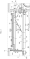
Figure 2 illustrates a detail of the machine ofFigure 1 . - As mentioned above, the machine described herein operates for producing containers filled with a product and sealed starting from a sheet of packaging material.
- The product may preferably be a liquid or else granular material.
- With reference to the preferred embodiment of
Figure 1 , the machine described herein - designated as a whole by the reference number 10 - comprises a system for feeding asheet 100 of packaging material that is able to feed thesheet 100 along a processing path K. Preferably, thesheet 100 is a web wound off a reel (not illustrated) and develops as a single continuous sheet along the entire processing path K. - In one or more preferred embodiments like the one illustrated, the
machine 10 comprises atank 20 that is set along the processing path K and contains a bath 20' (represented by a dashed line) in which thesheet 100 that advances along the processing path K is dipped. - Preferably, the bath 20' is constituted by a liquid of a sterilizing and/or sanitizing type.
- In one or more preferred embodiments like the one illustrated, the
tank 20 has a generic U shape, comprising a first branch orupstream branch 22A, a second branch ordownstream branch 22B, and abottom region 22C, which connects thefirst branch 22A to thesecond branch 22B and housed in which is adeflector roller 12, belonging to the system for feeding thesheet 100 and configured for bringing about a reversal of the direction of advance of the sheet 100 (from a top-down direction to a bottom-up direction). - Provided above the
first branch 22A is atop chamber 30, which constitutes a top region of thetank 20, whilst provided above thesecond branch 22B is a dryingchamber 40 for drying thesheet 100 after the latter has emerged from the bath 20'. - It should be noted that the
top chamber 30 and the dryingchamber 40 do not communicate directly with one another, but are, instead, connected together only through interposition of thetank 20. In operation, the presence of the bath 20' prevents any passage of air between the dryingchamber 40 and thetop chamber 30. - In one or more alternative embodiments, instead of the
tank 20, the machine may comprise devices of some other type for wetting thesheet 100 of packaging material with a sterilizing liquid, for example a sprayer device or else a roller-type applying device. - In a way in itself known, the drying
chamber 40 is equipped with a series of drying devices configured for drying the two opposite faces of thesheet 100 that advances inside the dryingchamber 40 along the processing path K. For instance, the dryingchamber 40 may comprise a pair of opposed squeezingrollers 42, which operate for compressing thesheet 100 in a direction transverse to the processing path K so as to expel the liquid absorbed by thesheet 100 into the bath 20'. Moreover, the dryingchamber 40 may comprise a pair of air-delivery heads 44, preferably for delivery of heated air, which are arranged on the two opposite sides of thesheet 100 and deliver a jet of air over the two opposite faces of thesheet 100. - Downstream of the drying
chamber 40, along the processing path K, themachine 10 comprises a formingchamber 60 within which thesheet 100 is formed to obtain the containers 101 filled with product and sealed. - In one or more preferred embodiments like the one illustrated, the forming
chamber 60 is provided with a forming device for curling thesheet 100 into a tube-like shape about an axis I that extends in a direction parallel to the processing path K within the formingchamber 60. Moreover, provided inside the chamber itself are sealing means for fixing together the opposite longitudinal flaps of thesheet 100 so as to close thesheet 100 and obtain a laterally sealedvertical tube 102. Thetube 102 is filled with the product to be packaged and extends downwards until it reaches afurther chamber 80, set downstream of the formingchamber 60. In thisfurther chamber 80, made on thetube 102 filled with the product are transverse sealing bands that identify, on thetube 102 itself,individual containers 110, which are then separated from thetube 102 via cutting. - The means for implementing the steps described above of forming, sealing, and cutting may be of a known type, and consequently will not be described in detail herein so as not to overburden the present treatment.
- In one or more preferred embodiments like the one illustrated, the
machine 10 further comprises a drying tunnel 50 that extends along the processing path K and connects together the dryingchamber 40, in particular adownstream end 40B thereof, and the formingchamber 60, in particular anupstream end 60A thereof. - The drying tunnel 50 is traversed by the
sheet 100 that advances along the processing path K from the dryingchamber 40 to the formingchamber 60. - In one or more preferred embodiments like the one illustrated, the
machine 10 comprises acompression unit 72 for feeding pressurized air into the formingchamber 60, and aunit 74 for suction of the air, which is connected to thetop chamber 30 and to the dryingchamber 40. - In a normal production cycle of the machine, the two
units chamber 60, traverses the drying tunnel 50, reaches the dryingchamber 40, and finally is sucked in by thesuction unit 74. - The above flow of air is first of all designed to bring about predefined ambient pressures in the drying
chamber 40 and in the formingchamber 60. - Moreover, within the suction tunnel 50, the above flow of air likewise exerts an action of drying on the
sheet 100, through a process of heat exchange by convection, with the purpose of removing the residue of the liquid of the bath 20' that has remained attached to the two opposite faces of thesheet 100 after the drying step carried out within the dryingchamber 40. - In particular, the flow of air enters the drying tunnel 50 through its
inlet 50A and exits from the tunnel through itsoutlet 50B. - According to an important characteristic of the machine described herein, the drying tunnel 50 has a
portion 52 with a cross section decreasing in the direction from the formingchamber 60 to the drying chamber 40 (i.e., in the direction of the flow of air). Thisportion 52 includes theinlet 50A. In one or more preferred embodiments like the one illustrated, the decreasing section of theportion 52 derives from the fact that theportion 52 itself has a height decreasing in the direction referred to above. - Moreover, in one or more preferred embodiments like the one illustrated, the drying tunnel 50 comprises a
second portion 54 with constant section, which includes theoutlet 50B. - As may be clearly seen in the figures, the maximum cross section of the
portion 52 with decreasing section represents the maximum cross section of the entire drying tunnel 50. - In one or more preferred embodiments like the one illustrated, the forming
chamber 60 is delimited by awall 62 that separates itsend 60A from the region of the machine that is upstream with reference to the direction of advance of thesheet 100. - In one or more preferred embodiments like the one illustrated, the
wall 62 comprises afirst opening 62A, which is traversed by the processing path K, and asecond opening 62B, preferably set above or below thefirst opening 62A, associated to which is avalve 76 configured for controlling a flow of air through theopening 62B. - In one or more preferred embodiments like the one illustrated, the
portion 52 with decreasing section of the drying tunnel is connected to thewall 62 and is set in fluid communication with the formingchamber 60, both through theopening 62A and through theopening 62B (this obviously according to the operating state of the valve 76). - In one or more preferred embodiments like the one illustrated, the drying tunnel 50 comprises a
horizontal bottom wall 53, which is fixed to thewall 62, at anend 531 thereof, and to avertical wall 11 of the machine, orthogonal to thewall 62, at the opposite end 53II. Moreover, the drying tunnel 50 comprises atop wall 55, which is also fixed to thewall 62, at an end 55I thereof, and to atop wall 12 of themachine 10, at its opposite end SSII. Thetop wall 55 has aninclined part 55A, which defines, together with thebottom wall 53, theportion 52 with decreasing section of the tunnel, and ahorizontal part 55B, which defines, together with thebottom wall 53, theportion 54 with constant section. The means for fixing the twowalls walls - With reference to
Figure 2 , extending alongside the drying tunnel 50 is a chamber 40' that communicates with the dryingchamber 40 and is substantially at the same internal pressure. - In one or more preferred embodiments like the one illustrated, the drying tunnel 50 has, along its extension, a series of
openings 57 that set the inside of the tunnel 50 in fluid communication with the chamber 40'; preferably, theopenings 57 are made in thetop wall 55. - In operation, the
portion 52 with decreasing section performs the function of bringing about an acceleration of the flow of air that enters the tunnel through theinlet 50A so as to increase the overall rate of the flow of air that traverses the tunnel 50, given the same jump in pressure between theinlet 50A and theoutlet 50B. - Moreover, the
inclined part 55A of thetop wall 55 determines, in the flow of air, a component of velocity of the air in a direction incident with to the processing path K inside the drying tunnel 50. This enables the flow of air to exert a more effective mechanical action for removing any possible residue of liquid present on thesheet 100. - Finally, it may be noted that through the
openings 57 minor portions of the flow of air flow into the chamber 40', which is substantially at the same pressure as the dryingchamber 40, and this circumstance contributes to limiting the jump in pressure between theinlet 50A and theoutlet 50B, without, however, eliminating the advantage in terms of higher flow rate obtained through theportion 52 with decreasing section. - On the other hand, it should be noted that after a machine stoppage there may be the need to carry out an operation of sterilization of the machine prior to start-up of a new production cycle, which envisages impinging upon the drying
chamber 40 and the formingchamber 60 with peroxide vapour mixed with air. Preliminarily, it is necessary to cool the inner walls of the two chambers in order to bring them to a temperature below the dewpoint of the peroxide vapour. - For this purpose, the
compression unit 72 and thesuction unit 74 are operated to get cooling air to circulate through thechambers - In this step, the
valve 76 is operated to define a maximum section of flow so as to allow a high flow rate of air through theopening 62B. In this way, a fast cooling of the twochambers - On the other hand, during a normal production cycle of the machine, the valve 56 can be operated to define a reduced section of flow.
- In one or more preferred embodiments like the one illustrated, the
valve 76 comprises a mobile open/close element 76C that has the very purpose of varying the section of flow of the valve, which is defined by anopening 76B obtained in thebody 76A of the valve. In one or more embodiments, the open/close element 76C is formed by a flap that can turn about an axis of rotation. - In one or more preferred embodiments like the one illustrated, the machine comprises a
control unit 90, configured for governing the valve according to a state signal W1 indicating an operating state of the machine. - In one or more preferred embodiments like the one illustrated, the machine comprises a
storage unit 92, stored in which is a set of operating parameters of the valve, which in particular comprises a first operating parameter V1, which defines the aforesaid maximum section of flow of the valve, and a second operating parameter V2, which defines the aforesaid reduced section of flow. - The
control unit 90 is configured for extracting the first operating parameter V1 and governing the valve on the basis of this, when it receives a state signal W1 indicating a process of washing and/or sterilization of the machine, and for extracting the second operating parameter V2 and governing the valve on the basis of this, when it receives a state signal W1 indicating a normal production cycle of the machine. Thecontrol unit 90, or a further control unit of the machine, is configured for governing also operation of thecompression unit 72 and of thesuction unit 74. The twounits - Preferably, the
compression unit 72 is controlled as a function of a signal indicating a flow rate in order to generate a flow of air characterized by a reference rate. - On the other hand, the
suction unit 74 is preferably controlled on the basis of a working parameter, the reference value of which to be used during operation of the machine is determined via an automatic calibration step. - Preferably, the above calibration step envisages a procedure in which a working parameter of the
suction unit 74 is varied as a function of a pressure signal W3 indicating the pressure inside the dryingchamber 40 and until a value of the above working parameter that determines a pressure inside the dryingchamber 40 itself equal to a desired pressure is reached. - The value of the working parameter thus reached is hence identified as effective value of the working parameter of the
suction unit 74 and stored as such in thestorage unit 92, then to be used during normal operation of the machine. - The working parameter in question may, for example, be a rate of rotation of a rotor of the
suction unit 74. - The
control unit 90 may be configured for implementing the aforesaid calibration step. - Preferably, the pressure signal W3 is obtained by a
pressure sensor 94 configured for detecting the pressure within the dryingchamber 40. - The aforesaid calibration step is started automatically by the machine when it is in a given operating state.
- For this purpose, the
control unit 90 may be configured for starting the calibration step on the basis of the state signal W1 referred to above, in particular when the state signal W1 itself indicates a step of start of the machine, for example the first start after installation or else a start after a prolonged machine stoppage. - The aforesaid calibration step enables the machine to identify automatically an optimal setting thereof, taking into account all the specificities of the layout of installation of the machine and of the working environment in which it is installed.
- Of course, without prejudice to the principle of the invention, the details of construction and the embodiments may vary, even significantly, with respect to what has been illustrated herein purely by way of non-limiting example, without thereby departing from the scope of the invention, as defined by the annexed claims.
Claims (15)
- A machine (10) for producing containers filled with a product and sealed, starting from a sheet (100) of packaging material, comprising:- a system for feeding said sheet (100) for making said sheet (100) advance in a direction of advance along a processing path (K);- a drying chamber (40), set along said processing path (K) and equipped with at least one drying device for drying said sheet (100) that advances along said processing path (K);- a forming chamber (60) in which said sheet (100) is formed so as to obtain said containers and which is set downstream of said drying chamber (40) along said processing path (K);- a drying tunnel (50), which extends along said processing path (K) and sets said drying chamber (40) and said forming chamber (60) in fluid communication with one another; and- an air-supply system (72, 74) connected to said forming chamber (60) for supplying a flow of air from said forming chamber (60) to said drying chamber (40), through said drying tunnel (50), within said drying tunnel (50) said flow of air having a direction opposite to the direction of advance of the sheet, wherein said drying tunnel (50) includes an inlet (50A), via which said flow of air enters the drying tunnel (50), and an outlet (50B), via which said flow of air exits from the drying tunnel (50),and said drying tunnel (50) having a portion (52) that has a cross section decreasing from the forming chamber (60) to the drying chamber (40) and includes said inlet (50A) of said drying tunnel (50).
- The machine according to claim 1, wherein said drying tunnel (50) comprises a second portion (54) that has a constant section and includes said outlet (50B) of said drying tunnel (50).
- The machine according to claim 1 or claim 2, wherein said portion (52) with decreasing section has a wall (55) configured to determine in said flow of air a component of velocity of the air in a direction incident to the processing path (K) within the drying tunnel (50).
- The machine according to any one of the preceding claims, wherein said portion (52) with decreasing section has a height that decreases from the forming chamber (60) to the drying chamber (40).
- The machine according to claim 2, wherein said drying tunnel (50) comprises a horizontal bottom wall (53) and a top wall (55), which has a first, inclined, part (55A) that defines, together with said bottom wall (53), said portion (52) with decreasing section, and a second, horizontal, part (55B) that defines, together with said bottom wall (53), said second portion (54) with constant section.
- The machine according to any one of the preceding claims, comprising a chamber (40') that extends alongside the drying tunnel (50) and is set in fluid communication with said drying chamber (40) so as to be substantially at the same pressure as said drying chamber,
wherein said drying tunnel (50) has along its extension a series of openings (57) that set in fluid communication the inside of said drying tunnel (50) with said chamber (40') so as to limit the jump in pressure between the opposite ends of said drying tunnel. - The machine according to any one of the preceding claims, comprising a wall (62), which delimits said forming chamber and connected to which is said portion (52) with decreasing section of the drying tunnel (50),wherein said wall (62) comprises a first opening (62A) and a second opening (62B) that both set said forming chamber and said portion (52) with decreasing section of the drying tunnel (50) in fluid communication with one another;wherein said first opening (62A) is traversed by the processing path (K); andwherein said machine comprises a valve (76) for controlling a flow of air that traverses the second opening (62B).
- The machine according to claim 7, wherein said valve (76) comprises an open/close element (76C) set at said second opening (62B) and mobile for varying a section of flow of said valve (76) set between said second opening (62B) and said forming chamber (60).
- The machine according to claim 8, wherein said open/close element (76C) is formed by a flap that can turn about an axis of rotation.
- The machine according to claim 7, comprising a control unit (90) configured to control said valve (76) as a function of a state signal (W1) indicating an operating state of the machine.
- The machine according to claim 10, comprising a storage unit (92) stored in which is a set of operating parameters (V1, V2) of said valve (76), each operating parameter of said set being such as to determine a given section of flow of said valve (76).
- The machine according to claim 11, wherein said set of operating parameters comprises at least a first operating parameter (V1) that determines a maximum section of flow of said valve (76), and at least a second operating parameter (V2) that determines a reduced section of flow of said valve (76), said reduced section of flow being smaller than said maximum section of flow.
- The machine according to claim 12, wherein said control unit (90) is configured to extract from said storage unit (92) said first operating parameter (V1) and to operate said valve (76) according to said first operating parameter, when said state signal indicates one between a process of washing and a process of sterilization of the machine, and to extract said second operating parameter (V2) and to operate said valve (76) according to said second operating parameter, when said state signal indicates a production state of the machine.
- A method for producing containers filled with a product and sealed, starting from a sheet (100) of packaging material, comprising the steps of:- making said sheet (100) advance in a direction of advance along a processing path (K);- drying said sheet (100) along said processing path (K), inside a drying chamber (40) and a drying tunnel (50) set downstream of said drying chamber (40) along said processing path (K);- forming said sheet (100) so as to obtain said containers (101) within a forming chamber (60) that is set downstream of said drying tunnel (50) along said processing path (K);- supplying a flow of air from said forming chamber (60) through said drying tunnel (50) in a direction opposite to the direction of advance of the sheet within said drying tunnel (50), said drying tunnel (50) including an inlet (50A) via which the flow of air enters the drying tunnel (50), an outlet (50B) via which the flow of air exits from the drying tunnel (50), and a portion (52) that has a cross section that decreases in the direction of the flow of air and includes the inlet (50A) of the drying tunnel (50);- via said portion (52) with decreasing section accelerating the flow of air that traverses said drying tunnel (50); and- suctioning said flow of air from said drying tunnel (50) at said drying chamber (40).
- The method according to claim 14, comprising:
via said portion (52) with decreasing section generating in said flow of air a component of velocity of the air in a direction incident to the processing path (K) within the drying tunnel (50).
Applications Claiming Priority (1)
| Application Number | Priority Date | Filing Date | Title |
|---|---|---|---|
| IT102023000020184A IT202300020184A1 (en) | 2023-09-29 | 2023-09-29 | MACHINE FOR MAKING CONTAINERS FILLED WITH A PRODUCT AND SEALED |
Publications (1)
| Publication Number | Publication Date |
|---|---|
| EP4534427A1 true EP4534427A1 (en) | 2025-04-09 |
Family
ID=89158398
Family Applications (1)
| Application Number | Title | Priority Date | Filing Date |
|---|---|---|---|
| EP24201975.0A Withdrawn EP4534427A1 (en) | 2023-09-29 | 2024-09-23 | Machine for producing containers filled with a product and sealed |
Country Status (2)
| Country | Link |
|---|---|
| EP (1) | EP4534427A1 (en) |
| IT (1) | IT202300020184A1 (en) |
Citations (2)
| Publication number | Priority date | Publication date | Assignee | Title |
|---|---|---|---|---|
| EP0127872A2 (en) * | 1983-06-03 | 1984-12-12 | Ab Tetra Pak | Arrangement for the treatment of a moving material web |
| EP1795448A1 (en) * | 2005-12-12 | 2007-06-13 | Tetra Laval Holdings & Finance SA | Air processing circuit for a sterilizing unit for sterilizing sheet packaging materials for packaging pourable food products, and sterilizing unit featuring such a circuit |
-
2023
- 2023-09-29 IT IT102023000020184A patent/IT202300020184A1/en unknown
-
2024
- 2024-09-23 EP EP24201975.0A patent/EP4534427A1/en not_active Withdrawn
Patent Citations (2)
| Publication number | Priority date | Publication date | Assignee | Title |
|---|---|---|---|---|
| EP0127872A2 (en) * | 1983-06-03 | 1984-12-12 | Ab Tetra Pak | Arrangement for the treatment of a moving material web |
| EP1795448A1 (en) * | 2005-12-12 | 2007-06-13 | Tetra Laval Holdings & Finance SA | Air processing circuit for a sterilizing unit for sterilizing sheet packaging materials for packaging pourable food products, and sterilizing unit featuring such a circuit |
Also Published As
| Publication number | Publication date |
|---|---|
| IT202300020184A1 (en) | 2025-03-29 |
Similar Documents
| Publication | Publication Date | Title |
|---|---|---|
| EP1334912B1 (en) | Unit for sterilizing web material on a machine for packaging pourable food products | |
| US8518325B2 (en) | Method of sterilizing a web of packaging material | |
| US6622457B2 (en) | Aseptically working packaging machine and method for pre-sterilizing them | |
| US5020303A (en) | Machine for filling containers with a food product | |
| US3820300A (en) | Method of and machine for producing sterile packages | |
| WO2003066443A1 (en) | Unit for sterilizing web-fed material on a machine for packaging pourable food products | |
| EP1795448B1 (en) | Air processing circuit for a sterilizing unit for sterilizing sheet packaging materials for packaging pourable food products, and sterilizing unit featuring such a circuit | |
| US6579082B2 (en) | Apparatus for the internal depressurization of plastic containers thermoformed by means of blowing and intended for sterile filling | |
| EP4345013A1 (en) | Machine for producing containers filled with a product and sealed | |
| CN1693563B (en) | Method and apparatus for multifilament stuffer box crimping | |
| AU2019200763A1 (en) | Vertical packaging machine for packaging products and associated method | |
| IT202300020184A1 (en) | MACHINE FOR MAKING CONTAINERS FILLED WITH A PRODUCT AND SEALED | |
| JPS6135045B2 (en) | ||
| EP4345019A1 (en) | Machine and method for producing containers filled with a product and sealed | |
| EP2406136B1 (en) | Method for providing a hygienic environment in a filling machine | |
| EP4345012A1 (en) | Method for producing containers filled with a product and sealed | |
| RU2796858C2 (en) | Vertical packaging machine for packaging products under modified atmosphere conditions | |
| JP3519780B2 (en) | Gas replacement device in a can of aerated food | |
| NL9002367A (en) | DEVICE FOR EVACUATING AND HYDRATING MUSHROOMS. | |
| JPH06278724A (en) | Positive pressure retainer for aseptic packaging device | |
| HK1126175B (en) | Packaging material sterilizing unit for a pourable food product packaging machine | |
| JPH0721656U (en) | Steam processing equipment | |
| HK1079494B (en) | Unit for sterilizing webfed material on a machine for packaging pourable food products |
Legal Events
| Date | Code | Title | Description |
|---|---|---|---|
| PUAI | Public reference made under article 153(3) epc to a published international application that has entered the european phase |
Free format text: ORIGINAL CODE: 0009012 |
|
| STAA | Information on the status of an ep patent application or granted ep patent |
Free format text: STATUS: THE APPLICATION HAS BEEN PUBLISHED |
|
| AK | Designated contracting states |
Kind code of ref document: A1 Designated state(s): AL AT BE BG CH CY CZ DE DK EE ES FI FR GB GR HR HU IE IS IT LI LT LU LV MC ME MK MT NL NO PL PT RO RS SE SI SK SM TR |
|
| STAA | Information on the status of an ep patent application or granted ep patent |
Free format text: STATUS: REQUEST FOR EXAMINATION WAS MADE |
|
| 17P | Request for examination filed |
Effective date: 20250808 |
|
| STAA | Information on the status of an ep patent application or granted ep patent |
Free format text: STATUS: THE APPLICATION HAS BEEN WITHDRAWN |
|
| 18W | Application withdrawn |
Effective date: 20260402 |