EP4534412A1 - Appareil et procédés pour aéronef à ailes en treillis transsonique entretoisées - Google Patents
Appareil et procédés pour aéronef à ailes en treillis transsonique entretoisées Download PDFInfo
- Publication number
- EP4534412A1 EP4534412A1 EP24202155.8A EP24202155A EP4534412A1 EP 4534412 A1 EP4534412 A1 EP 4534412A1 EP 24202155 A EP24202155 A EP 24202155A EP 4534412 A1 EP4534412 A1 EP 4534412A1
- Authority
- EP
- European Patent Office
- Prior art keywords
- engine
- pylon
- strut
- truss
- wing
- Prior art date
- Legal status (The legal status is an assumption and is not a legal conclusion. Google has not performed a legal analysis and makes no representation as to the accuracy of the status listed.)
- Pending
Links
Images


Classifications
-
- B—PERFORMING OPERATIONS; TRANSPORTING
- B64—AIRCRAFT; AVIATION; COSMONAUTICS
- B64C—AEROPLANES; HELICOPTERS
- B64C1/00—Fuselages; Constructional features common to fuselages, wings, stabilising surfaces or the like
- B64C1/26—Attaching the wing or tail units or stabilising surfaces
-
- B—PERFORMING OPERATIONS; TRANSPORTING
- B64—AIRCRAFT; AVIATION; COSMONAUTICS
- B64C—AEROPLANES; HELICOPTERS
- B64C3/00—Wings
- B64C3/10—Shape of wings
- B64C3/14—Aerofoil profile
-
- B—PERFORMING OPERATIONS; TRANSPORTING
- B64—AIRCRAFT; AVIATION; COSMONAUTICS
- B64C—AEROPLANES; HELICOPTERS
- B64C3/00—Wings
- B64C3/32—Wings specially adapted for mounting power plant
-
- B—PERFORMING OPERATIONS; TRANSPORTING
- B64—AIRCRAFT; AVIATION; COSMONAUTICS
- B64D—EQUIPMENT FOR FITTING IN OR TO AIRCRAFT; FLIGHT SUITS; PARACHUTES; ARRANGEMENT OR MOUNTING OF POWER PLANTS OR PROPULSION TRANSMISSIONS IN AIRCRAFT
- B64D27/00—Arrangement or mounting of power plants in aircraft; Aircraft characterised by the type or position of power plants
- B64D27/02—Aircraft characterised by the type or position of power plants
-
- B—PERFORMING OPERATIONS; TRANSPORTING
- B64—AIRCRAFT; AVIATION; COSMONAUTICS
- B64D—EQUIPMENT FOR FITTING IN OR TO AIRCRAFT; FLIGHT SUITS; PARACHUTES; ARRANGEMENT OR MOUNTING OF POWER PLANTS OR PROPULSION TRANSMISSIONS IN AIRCRAFT
- B64D27/00—Arrangement or mounting of power plants in aircraft; Aircraft characterised by the type or position of power plants
- B64D27/40—Arrangements for mounting power plants in aircraft
- B64D27/402—Arrangements for mounting power plants in aircraft comprising box like supporting frames, e.g. pylons or arrangements for embracing the power plant
-
- B—PERFORMING OPERATIONS; TRANSPORTING
- B64—AIRCRAFT; AVIATION; COSMONAUTICS
- B64F—GROUND OR AIRCRAFT-CARRIER-DECK INSTALLATIONS SPECIALLY ADAPTED FOR USE IN CONNECTION WITH AIRCRAFT; DESIGNING, MANUFACTURING, ASSEMBLING, CLEANING, MAINTAINING OR REPAIRING AIRCRAFT, NOT OTHERWISE PROVIDED FOR; HANDLING, TRANSPORTING, TESTING OR INSPECTING AIRCRAFT COMPONENTS, NOT OTHERWISE PROVIDED FOR
- B64F5/00—Designing, manufacturing, assembling, cleaning, maintaining or repairing aircraft, not otherwise provided for; Handling, transporting, testing or inspecting aircraft components, not otherwise provided for
- B64F5/10—Manufacturing or assembling aircraft, e.g. jigs therefor
-
- B—PERFORMING OPERATIONS; TRANSPORTING
- B64—AIRCRAFT; AVIATION; COSMONAUTICS
- B64C—AEROPLANES; HELICOPTERS
- B64C3/00—Wings
- B64C3/10—Shape of wings
- B64C3/14—Aerofoil profile
- B64C2003/149—Aerofoil profile for supercritical or transonic flow
Definitions
- This disclosure relates generally to aircraft and, more particularly, to apparatus and methods for transonic truss-braced wing aircraft.
- Transonic aircraft face challenges managing airflow and drag on the wings as air speeds approach the speed of sound.
- the wings of transonic aircraft are carefully designed to manage airflow, but many wing designs are limited by structural requirements, engine placements, and control surface requirements.
- Some transonic aircraft are designed with trusses that support the wings, thereby reducing the loads on the wing structures and the size of the structures required to support those loads.
- Many transonic truss-braced wing aircraft take advantage of these reduced structural requirements to lengthen wing spans and shorten chord lengths of the wings, thus improving wing performance at transonic speeds.
- An example aircraft disclosed herein includes a fuselage and a wing supported by a truss.
- the truss includes a pylon coupled to and extending from the fuselage and a strut attached to the wing.
- An engine is coupled to the pylon.
- An example truss to support a wing of an aircraft disclosed herein includes a strut to be coupled to the wing, a pylon to be coupled to the strut and further to be coupled to the aircraft.
- the pylon is to receive an engine.
- a first part is above a second part, if the second part has at least one part between Earth and the first part.
- a first part is "below” a second part when the first part is closer to the Earth than the second part.
- a first part can be above or below a second part with one or more of: other parts therebetween, without other parts therebetween, with the first and second parts touching, or without the first and second parts being in direct contact with one another.
- any part e.g., a layer, film, area, region, or plate
- any part e.g., a layer, film, area, region, or plate
- the referenced part is either in contact with the other part, or that the referenced part is above the other part with one or more intermediate part(s) located therebetween.
- descriptors such as “first,” “second,” “third,” etc. are used herein without imputing or otherwise indicating any meaning of priority, physical order, arrangement in a list, and/or ordering in any way, but are merely used as labels and/or arbitrary names to distinguish elements for ease of understanding the disclosed examples.
- “approximately” and “about” modify their subjects/values to recognize the potential presence of variations that occur in real world applications. For example, “approximately” and “about” may modify dimensions that may not be exact due to manufacturing tolerances and/or other real world imperfections as will be understood by persons of ordinary skill in the art. For example, “approximately” and “about” may indicate such dimensions may be within a tolerance range of +/- 10% unless otherwise specified in the below description.
- Cantilever wings e.g., unsupported wings
- Cantilever wings must be sized and designed withstand the working loads (e.g., weight of the wings, weight of the aircraft, lift forces, engine thrust, etc.) of the aircraft in flight, which results in a minimum cross-sectional area and related chord length.
- the aerodynamic performance of the wing e.g., lift to drag ratio, aspect ratio, etc. is limited by the self-supporting nature of the cantilever wing.
- removing the engines from the wings allows some example truss-braced wings to improve high-lift performance with a more continuous spanload and/or uninterrupted high-lift system(s).
- engines mounted on a pylon of a truss are positioned closer to a center of gravity of the aircraft, when compared to known aircraft, which advantageously places engine thrust closer to the center of gravity and reduces related trim drag on the aircraft and/or improves aircraft efficiency.
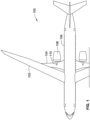
- the loading of the example truss-braced wing 102 of aircraft 100 is substantially reduced by moving the engine 108 to the truss 104, which allows further optimization of the wing 102.
- the chord length of the wing 102 can be further reduced and the span of the wing 102 can be increased as the wing 102 no longer needs to support the full loads of the engine 108.
- the wing 102 is no longer constrained to carry the engine support systems (e.g., engine pylons, fuel lines, engine control systems), all of which would require space in the wing 102.
- control surfaces e.g., flaps, ailerons, etc.
- the control surfaces (e.g., flaps, ailerons, etc.) of wing 102 also benefit from the engine 108 being supported by truss 104, as the control surfaces can operate without aerodynamic interference from the engine 108 or its supporting structures. This benefit can be particularly advantageous for high-lift performance as the wing 102 has a more continuous spanload (e.g., lift) and uninterrupted high-lift systems (e.g., flaps).
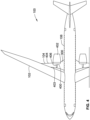
- Example positions of the engine 402 can include the intake 400 fore of the pylon 300 (e.g., fore of the leading edge or the fore edge 403), the intake 400 being at any intermediate position between fore of the pylon 300 and fore of the aft edge 404 of the pylon 300, and/or any other position(s).
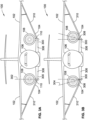
- FIG. 5 illustrates a partial top view of another example aircraft 500 disclosed herein having an example forward swept wing 502.
- the example aircraft 500 of the illustrated example includes an example engine 504 coupled to an example pylon 506 of an example truss 508.
- An example engine strut 510 supports the engine 504 and couples the engine 504 and the pylon 506.
- the engine 504 is positioned fore of the truss 508.
- at least a portion of the engine 504 is positioned fore of a fore edge 509 (e.g., a leading edge) of the pylon 506.
- the engine strut 510 can be coupled anywhere along the pylon 506 (e.g., the engine strut 510 can be positioned at different locations along a longitudinal length of the pylon 506 between a first end or inboard end which attaches to the fuselage 512 and a second end or outboard end opposite the first end that attaches to an example strut 702).
- the example engine strut 510 is coupled at an example angle (e.g., perpendicular to a centerline of pylon 506).
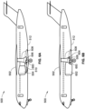
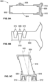
- FIG. 8 illustrates a partial top view of the example aircraft 500 of FIG. 5 with an example exhaust outlet 800 of an example engine 802 positioned aft of the fore edge 509 (e.g., the leading edge) of the example pylon 506.
- the engine 802 is coupled to the pylon 506 with an example engine strut 806.
- the engine strut 806 has an example length and position on the pylon 506, but the exact length and/or position can vary. At least a portion of the engine 802 overlaps or is positioned over the fore edge 509 of the pylon 506 at an example position. Thus, the engine 802 of the illustrated example straddles the fore edge 509 of the pylon 506.
- FIG. 9B is a front view of the example mounting hardware of FIG. 9A .
- the second strut fitting 912 and the third strut fitting 914 are positioned to receive mating fittings of an example engine strut (shown in FIG. 10 ).
- the first brace fitting 908 is positioned to receive a bracing link.
- the first strut fitting 910 is positioned to receive a lower link.
- the aforementioned fittings allow for a secure coupling of an engine to the pylon 900 (further detailed in FIG. 10 ).
- FIG. 10 illustrates an example engine nacelle 1000 coupled to the example pylon 900 of FIGS. 9A-9B with example engine struts (e.g., a first engine strut 1002, a second engine strut 1004).
- the first engine strut 1002 is coupled to a top side 1006 of the pylon 900.
- the second strut fitting 912 (fixed on an aft edge of the top side 1006 of pylon 900) couples to an example fourth strut fitting 1008 (fixed on a fore edge of a bottom side 1010 of the first engine strut 1002).
- the engine nacelle 1000 of FIG. 10 is positioned above an aft edge of the pylon 900. In other examples, the engine nacelle 1000 is positioned above the fore edge of the pylon 900, with the mounting hardware switched from aft to fore.
- the orientation of the engine nacelle 1000 and the distance between the pylon 900 and the engine nacelle 1000 can vary to meet the needs of the aircraft 100 (e.g., weight distribution, aerodynamics, thrust characteristics, etc.).
- the engine nacelle 1000 can be directly coupled to the first engine strut 1002.
- an example cowling 1024 of the engine nacelle 1000 may contact mounting hardware (e.g., second brace fitting 1018, diagonal brace 1020, etc.) when mounted directly to the first engine strut 1002.
- the example engine nacelle 1000 of FIG. 10 is coupled to the first engine strut 1002 through a second engine strut 1004, thereby allowing the cowling 1024 to remain spaced from mounting hardware.
- the second engine strut 1004 is an example height from a bottom side 1026 to a top side 1028, but other example second engine struts 1004 can have different heights to raise or lower the engine nacelle 1000 relative to the pylon 900.
- the example engine nacelle of FIG. 10 is coupled to the top side 1028 of the second engine strut 1004.
- An example forward mount 1030 couples to a fore section of the top side 1028 of the second engine strut 1004 and to a fore section of the engine nacelle 1000.
- An example aft mount 1032 couples to an aft section of the top side 1028 of the second engine strut 1004 and to an aft section of the engine nacelle 1000.
- An example thrust link 1034 is coupled to an aft section of the top side 1028 of the second engine strut 1004 and to a fore section of the engine nacelle 1000.
- the example pylon 900, engine struts and/or nacelles of FIGS. 9-10 can be employed to mount the different example engines 108, 402, 504, 602, 802 to the example pylons 300, 506, and/or the truss 104, 508 disclosed herein.
- a second engine strut is coupled between the first engine strut and the engine nacelle.
- any number of engine struts are coupled between the pylon and the engine nacelle, allowing the engine nacelle to be positioned at different locations relative to the pylon.
Landscapes
- Engineering & Computer Science (AREA)
- Aviation & Aerospace Engineering (AREA)
- Mechanical Engineering (AREA)
- Manufacturing & Machinery (AREA)
- Transportation (AREA)
- Structures Of Non-Positive Displacement Pumps (AREA)
Applications Claiming Priority (1)
| Application Number | Priority Date | Filing Date | Title |
|---|---|---|---|
| US18/482,600 US12522341B2 (en) | 2023-10-06 | 2023-10-06 | Apparatus and methods for transonic truss-braced wing aircraft |
Publications (1)
| Publication Number | Publication Date |
|---|---|
| EP4534412A1 true EP4534412A1 (fr) | 2025-04-09 |
Family
ID=92899813
Family Applications (1)
| Application Number | Title | Priority Date | Filing Date |
|---|---|---|---|
| EP24202155.8A Pending EP4534412A1 (fr) | 2023-10-06 | 2024-09-24 | Appareil et procédés pour aéronef à ailes en treillis transsonique entretoisées |
Country Status (3)
| Country | Link |
|---|---|
| US (2) | US12522341B2 (fr) |
| EP (1) | EP4534412A1 (fr) |
| CN (1) | CN119773953A (fr) |
Citations (3)
| Publication number | Priority date | Publication date | Assignee | Title |
|---|---|---|---|---|
| US2398704A (en) * | 1943-05-03 | 1946-04-16 | Ridgefield Mfg Corp | Engine nacelle installation for aircraft |
| US20130020433A1 (en) * | 2011-07-24 | 2013-01-24 | Hoisington Zachary C | Reduced flow field velocity for a propulsor |
| US20190300160A1 (en) * | 2018-03-29 | 2019-10-03 | Rolls-Royce Plc | Multi-function strut |
Family Cites Families (6)
| Publication number | Priority date | Publication date | Assignee | Title |
|---|---|---|---|---|
| DE69430198T2 (de) * | 1994-12-16 | 2003-07-10 | Aldo Frediani | Grossraumflugzeug |
| ES2377637B1 (es) * | 2009-04-07 | 2013-02-28 | Airbus Operations, S.L. | Avión con configuración alar en caja lambda. |
| FR2989063B1 (fr) * | 2012-04-05 | 2015-01-02 | Airbus Operations Sas | Procede de couplage dissociable entre un module de propulsion et un module de transport d’un avion et avion modulaire de mise en oeuvre |
| ES2711660B2 (es) * | 2017-11-02 | 2020-06-17 | Ottonello Carlos Cesar Manterola | Conjunto de tres alas compuestas para vehículos aéreos, acuáticos, terrestres o espaciales |
| US10933970B2 (en) * | 2018-03-28 | 2021-03-02 | The Boeing Company | Aircraft with strut-braced wing system |
| EP3725671B1 (fr) * | 2019-04-15 | 2023-09-27 | Safran Landing Systems UK Ltd | Aéronef ayant un train d'atterrissage à stabilisateur |
-
2023
- 2023-10-06 US US18/482,600 patent/US12522341B2/en active Active
-
2024
- 2024-09-23 CN CN202411326973.4A patent/CN119773953A/zh active Pending
- 2024-09-24 EP EP24202155.8A patent/EP4534412A1/fr active Pending
-
2025
- 2025-12-16 US US19/422,030 patent/US20260103274A1/en active Pending
Patent Citations (3)
| Publication number | Priority date | Publication date | Assignee | Title |
|---|---|---|---|---|
| US2398704A (en) * | 1943-05-03 | 1946-04-16 | Ridgefield Mfg Corp | Engine nacelle installation for aircraft |
| US20130020433A1 (en) * | 2011-07-24 | 2013-01-24 | Hoisington Zachary C | Reduced flow field velocity for a propulsor |
| US20190300160A1 (en) * | 2018-03-29 | 2019-10-03 | Rolls-Royce Plc | Multi-function strut |
Also Published As
| Publication number | Publication date |
|---|---|
| US20260103274A1 (en) | 2026-04-16 |
| CN119773953A (zh) | 2025-04-08 |
| US20250115346A1 (en) | 2025-04-10 |
| US12522341B2 (en) | 2026-01-13 |
Similar Documents
| Publication | Publication Date | Title |
|---|---|---|
| CA2634307C (fr) | Aile d'aeronef et contours de fuselage | |
| EP2418148B1 (fr) | Avion à configuration alaire lambdoïde | |
| US5897076A (en) | High-efficiency, supersonic aircraft | |
| US9868540B2 (en) | Aircraft engine mounting system | |
| US5322242A (en) | High efficiency, supersonic aircraft | |
| US8353478B1 (en) | Blended wing aircraft | |
| US6929219B2 (en) | Derivative aircraft and methods for their manufacture | |
| US8322655B1 (en) | Twin-boom empennage | |
| US8061655B1 (en) | Aircraft configuration utilizing fuselage, wing, empennage, and exhaust flow control devices | |
| US11780567B2 (en) | Wingtip device for an aircraft | |
| US12377993B2 (en) | Engine attachment system for aircraft and method for attaching an engine | |
| CN115535211A (zh) | 飞机及制造飞机的方法 | |
| US8567711B1 (en) | Swept-wing powered-lift aircraft | |
| US8167249B1 (en) | Controllable upper surface blown nozzle | |
| US20220242565A1 (en) | Methods for improvements of the closed wing aircraft concept and corresponding aircraft configurations | |
| EP4534412A1 (fr) | Appareil et procédés pour aéronef à ailes en treillis transsonique entretoisées | |
| US11584506B2 (en) | Aircraft wing assemblies | |
| US20260054823A1 (en) | Truss-braced wing aircraft engine mounting and associated systems | |
| Schoensleben | Integrated trailing edge flap track mechanism for commercial aircraft | |
| CN120397270A (zh) | 具有翼上发动机位置的飞行器 |
Legal Events
| Date | Code | Title | Description |
|---|---|---|---|
| PUAI | Public reference made under article 153(3) epc to a published international application that has entered the european phase |
Free format text: ORIGINAL CODE: 0009012 |
|
| STAA | Information on the status of an ep patent application or granted ep patent |
Free format text: STATUS: THE APPLICATION HAS BEEN PUBLISHED |
|
| AK | Designated contracting states |
Kind code of ref document: A1 Designated state(s): AL AT BE BG CH CY CZ DE DK EE ES FI FR GB GR HR HU IE IS IT LI LT LU LV MC ME MK MT NL NO PL PT RO RS SE SI SK SM TR |
|
| STAA | Information on the status of an ep patent application or granted ep patent |
Free format text: STATUS: REQUEST FOR EXAMINATION WAS MADE |
|
| 17P | Request for examination filed |
Effective date: 20250923 |