EP4534404A1 - Title of invention: method for controlling ship, ship control program, ship control system, and ship - Google Patents
Title of invention: method for controlling ship, ship control program, ship control system, and ship Download PDFInfo
- Publication number
- EP4534404A1 EP4534404A1 EP24199336.9A EP24199336A EP4534404A1 EP 4534404 A1 EP4534404 A1 EP 4534404A1 EP 24199336 A EP24199336 A EP 24199336A EP 4534404 A1 EP4534404 A1 EP 4534404A1
- Authority
- EP
- European Patent Office
- Prior art keywords
- ship
- power
- power source
- motor
- actuator
- Prior art date
- Legal status (The legal status is an assumption and is not a legal conclusion. Google has not performed a legal analysis and makes no representation as to the accuracy of the status listed.)
- Granted
Links
Images




Classifications
-
- B—PERFORMING OPERATIONS; TRANSPORTING
- B63—SHIPS OR OTHER WATERBORNE VESSELS; RELATED EQUIPMENT
- B63H—MARINE PROPULSION OR STEERING
- B63H21/00—Use of propulsion power plant or units on vessels
- B63H21/20—Use of propulsion power plant or units on vessels the vessels being powered by combinations of different types of propulsion units
-
- B—PERFORMING OPERATIONS; TRANSPORTING
- B63—SHIPS OR OTHER WATERBORNE VESSELS; RELATED EQUIPMENT
- B63H—MARINE PROPULSION OR STEERING
- B63H21/00—Use of propulsion power plant or units on vessels
- B63H21/21—Control means for engine or transmission, specially adapted for use on marine vessels
-
- B—PERFORMING OPERATIONS; TRANSPORTING
- B63—SHIPS OR OTHER WATERBORNE VESSELS; RELATED EQUIPMENT
- B63B—SHIPS OR OTHER WATERBORNE VESSELS; EQUIPMENT FOR SHIPPING
- B63B79/00—Monitoring properties or operating parameters of vessels in operation
- B63B79/10—Monitoring properties or operating parameters of vessels in operation using sensors, e.g. pressure sensors, strain gauges or accelerometers
-
- B—PERFORMING OPERATIONS; TRANSPORTING
- B63—SHIPS OR OTHER WATERBORNE VESSELS; RELATED EQUIPMENT
- B63B—SHIPS OR OTHER WATERBORNE VESSELS; EQUIPMENT FOR SHIPPING
- B63B79/00—Monitoring properties or operating parameters of vessels in operation
- B63B79/30—Monitoring properties or operating parameters of vessels in operation for diagnosing, testing or predicting the integrity or performance of vessels
-
- B—PERFORMING OPERATIONS; TRANSPORTING
- B63—SHIPS OR OTHER WATERBORNE VESSELS; RELATED EQUIPMENT
- B63B—SHIPS OR OTHER WATERBORNE VESSELS; EQUIPMENT FOR SHIPPING
- B63B79/00—Monitoring properties or operating parameters of vessels in operation
- B63B79/40—Monitoring properties or operating parameters of vessels in operation for controlling the operation of vessels, e.g. monitoring their speed, routing or maintenance schedules
-
- B—PERFORMING OPERATIONS; TRANSPORTING
- B63—SHIPS OR OTHER WATERBORNE VESSELS; RELATED EQUIPMENT
- B63H—MARINE PROPULSION OR STEERING
- B63H23/00—Transmitting power from propulsion power plant to propulsive elements
- B63H23/02—Transmitting power from propulsion power plant to propulsive elements with mechanical gearing
- B63H23/10—Transmitting power from propulsion power plant to propulsive elements with mechanical gearing for transmitting drive from more than one propulsion power unit
- B63H23/12—Transmitting power from propulsion power plant to propulsive elements with mechanical gearing for transmitting drive from more than one propulsion power unit allowing combined use of the propulsion power units
-
- B—PERFORMING OPERATIONS; TRANSPORTING
- B63—SHIPS OR OTHER WATERBORNE VESSELS; RELATED EQUIPMENT
- B63H—MARINE PROPULSION OR STEERING
- B63H21/00—Use of propulsion power plant or units on vessels
- B63H21/20—Use of propulsion power plant or units on vessels the vessels being powered by combinations of different types of propulsion units
- B63H2021/202—Use of propulsion power plant or units on vessels the vessels being powered by combinations of different types of propulsion units of hybrid electric type
-
- B—PERFORMING OPERATIONS; TRANSPORTING
- B63—SHIPS OR OTHER WATERBORNE VESSELS; RELATED EQUIPMENT
- B63H—MARINE PROPULSION OR STEERING
- B63H21/00—Use of propulsion power plant or units on vessels
- B63H21/21—Control means for engine or transmission, specially adapted for use on marine vessels
- B63H2021/216—Control means for engine or transmission, specially adapted for use on marine vessels using electric control means
Definitions
- the present disclosure relates to a method for controlling a ship including a plurality of power sources, a ship control program, a ship control system, and a ship.
- a method for controlling a ship including a plurality of power sources, such as an engine and a motor a method for performing switching among a plurality of operation modes including a mode for propulsion by an engine, a mode for propulsion by a motor, a mode for propulsion by an engine and a motor, and an electric power generation mode from one to another has been used (refer to Patent Document 1, for example).
- Ships according to the related art include, in addition to a plurality of power sources, a power transmitter, an outputter, and an actuator.
- the power transmitter transmits power from at least one of the plurality of power sources to the outputter including a propeller to generate a propulsive force of a hull.
- the actuator serving as a shifter switches a connection state of the power transmitter by driving a clutch included in the power transmitter, such as a meshing type clutch including a dog clutch, for example, so as to perform switching among the plurality of operation modes.
- Patent Document 1 Japanese Unexamined Patent Application Publication No. 2023-037810
- an operation mode in the plurality of propulsion modes is specified based on an operation state of the actuator. Therefore, for example, when an abnormality occurs in the actuator due to a failure of the actuator or the like, a management state of the operation mode may deviate from an actual operation mode.
- An object of the present disclosure is to provide a method for controlling a ship, a ship control program, a ship control system, and a ship which can improve reliability of a management state of an operation mode.
- a method for controlling a ship is employed in a ship that has a plurality of power sources including a first power source and a second power source and that propels a hull by transmitting power from at least one of the plurality of power sources through a power transmitter to a propulsive force generator.
- the method includes determining at least two of the first power source, the second power source, and the propulsive force generator as comparison targets and comparing rotation speeds of the comparison targets with each other, and determining an abnormality of at least one of an actuator that drives the power transmitter and the power transmitter based on a result of the comparison between the rotation speeds.
- a ship control program causes at least one processor to execute the method for controlling a ship.
- the method for controlling a ship is employed in a ship that has a plurality of power sources including a first power source and a second power source and that propels a hull by transmitting power from at least one of the plurality of power sources through a power transmitter to a propulsive force generator.
- the ship control system includes a comparison processor and an abnormality determination processor.
- the comparison processor determines at least two of the first power source, the second power source, and the propulsive force generator as comparison targets, and compares rotation speeds of the comparison targets with each other.
- the abnormality determination processor determines an abnormality of at least one of the actuator that drives the power transmitter and the power transmitter based on a result of the comparison between the rotation speeds.
- a ship according to still another aspect of the present disclosure includes the ship control system and the hull.
- a method for controlling a ship, a ship control program, a ship control system, and a ship that can improve reliability of a management state of an operation mode are provided.
- the ship 10 is a moving body that sails (navigates) on water, such as ocean, lake, or river.
- the ship 10 is a "pleasure boat” that is a small-sized ship mainly used for sport, recreation, or the like.
- the ship 10 is operated in accordance with an operation (including a remote operation) performed by a person (an operator), and in particular, the ship 10 is of a manned type that can be boarded by the person as the operator.
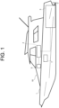
- the ship 10 includes a hull 1, a power source device 7, and a ship control system 2 as illustrated in FIG. 1 .
- the hull 1 includes a driving unit 3 that generates power, a propulsive force generator 4 that outputs a propulsive force for propelling the hull 1, and an operation device 5 that accepts an operation performed by a person (operator).
- the hull 1 further includes various onboard facilities including a rudder mechanism, a communication device, and a lighting facility.
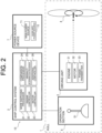
- the driving unit 3 includes, as illustrated in FIG. 2 , an engine 31 serving as a first power source, a motor 32 serving as a second power source, and a power transmitter 33.
- the propulsive force generator 4 including a propeller in this embodiment receives dynamic power generated by the driving unit 3 and rotates the propeller around a rotation shaft (propeller shaft), to thereby generate the propulsive force to move the hull 1 forward or rearward.
- the plurality of power sources including the first power source (engine 31) and the second power source (motor 32) individually generate power (mechanical energy) to be used for propelling the hull 1.
- the plurality of power sources have different output characteristics from each other, and have at least different maximum outputs (maximum rotation speeds and maximum torques).
- the plurality of power sources are completely different types of power source employing different methods.
- the ship 10 according to this embodiment includes the hybrid driving unit 3 having the plurality of types of power source.
- the first power source is the engine (internal combustion engine) 31 that generates power by burning of fuel and the second power source is the motor (electric motor) 32 that generates power by supplied electric power (electric energy).
- the engine 31 is a diesel engine that is driven with light oil as fuel
- the motor 32 is an AC motor driven by AC power.
- the engine 31 and the motor 32 are individually driven and individually generate power. Therefore, the plurality of power sources can be switched among, for example, a state in which only the engine 31 between the engine 31 and the motor 32 is driven, a state in which only the motor 32 is driven, and a state in which both the engine 31 and the motor 32 are driven.
- the power generated by the engine 31 and the power generated by the motor 32 are combined by the power transmitter 33, and the combined power is supplied to the propulsive force generator 4. Therefore, since the power of the engine 31 is combined with the power of the motor 32, the motor 32 can assist the engine 31 so that the propulsive force generator 4 is driven by a larger power.
- the power transmitter 33 is disposed between the plurality of power sources (engine 31 and motor 32) and the propulsive force generator 4.
- the power transmitter 33 has a function of receiving power generated by the plurality of power sources as inputs and transmitting the power to the propulsive force generator 4.
- the power transmitter 33 combines power supplied from the plurality of power sources (engine 31 and motor 32) and outputs the combined power to the propulsive force generator 4.
- the power transmitter 33 has a function of determining whether power is to be transmitted from the plurality of power sources (engine 31 and motor 32) to the propulsive force generator 4, that is, a function of performing switching between a "transmission state” and a "block state” from one to another.
- the term "transmission state” in the present disclosure indicates a state in which the plurality of power sources (engine 31 and motor 32) and the propulsive force generator 4 are mechanically connected to each other and power is transmitted from the power sources to the propulsive force generator 4.
- the propulsive force generator 4 is driven by the power generated by the power sources.
- block state indicates a state in which the power sources (engine 31 and motor 32) and the propulsive force generator 4 are mechanically disconnected from one another so that power is not transmitted from the power sources to the propulsive force generator 4. Since power generated by the power sources is not transmitted to the propulsive force generator 4 even when the power sources (engine 31 and motor 32) are driven in the block state of the power transmitter 33, the propulsive force generator 4 is not driven.
- the power transmitter 33 further has a function of switching a coupling state between the plurality of power sources (engine 31 and motor 32). Specifically, the power transmitter 33 has a function of performing switching between a coupling state" in which the first power source (engine 31) and the second power source (motor 32) are mechanically coupled with each other and an "independent state” in which the first power source (engine 31) and the second power source (motor 32) are disconnected from each other.
- connection state in the present disclosure indicates a state in which the first and second power sources are mechanically connected to each other so that power is transmitted between the first and second power sources.
- the driving unit 3 will be described in detail in a section of "2. Configuration of Driving Unit".
- the ship control system 2 at least controls the driving unit 3. That is, the ship control system 2 controls, for example, driving states of the engine 31 and the motor 32 and a state of the power transmitter 33 (transmission state/block state, coupling state/independent state, and the like).
- the ship control system 2 is electrically connected to the operation device 5, and controls the driving unit 3 and the like in accordance with an operation signal supplied from the operation device 5.
- the ship control system 2 controls the driving unit 3 in accordance with an operation signal supplied from the operation device 5 so as to rotate the propeller of the propulsive force generator 4 to thereby move the hull 1 forward and rearward.
- the ship control system 2 can adjust a rotation speed of the propeller of the propulsive force generator 4 by controlling an output (rotation speed or torque) of the engine 31 or the motor 32 so as to adjust a movement speed (ship speed) of the hull 1.
- the ship control system 2 can switch a plurality of operation modes from one to another.
- the term "operation mode" represents various modes of different connection states (transmission state/block state, coupling state/independent state, and the like) of the power transmitter 33, and includes, for example, modes of different power sources to be used for propelling the hull 1 among the plurality of power sources (engine 31 and motor 32).
- a plurality of operation modes can be switched from one to another by performing switching among the connection states of the power transmitter 33.
- the plurality of operation modes include a motor propulsion mode, an engine propulsion mode, an electric power generation mode, and a hybrid propulsion mode.
- the motor propulsion mode only the motor 32, between the engine 31 and the motor 32, is used for propelling the hull 1.
- the engine propulsion mode only the engine 31, between the engine 31 and the motor 32, is used for propelling the hull 1.
- the electric power generation mode the motor 32 is driven by power generated by the engine 31 and the motor 32 generates electric power as an electric power generator.
- the hybrid propulsion mode both the engine 31 (first power source) and the motor 32 (second power source) are used for propelling the hull 1.
- the ship control system 2 is an integrated controller that controls the entire hull 1, and includes an electronic control unit (ECU), for example.
- ECU electronice control unit
- the ship control system 2 may be disposed separately from the integrated controller. A detailed description will be made on the ship control system 2 in a section "3. Configuration of Ship Control System".
- the operation device 5 is a user interface that accepts an operation performed by a person (operator) and is installed in an operation room where the operator boards in the hull 1.
- the operation device 5 accepts various operations performed by the operator and outputs electric signals (operation signals) corresponding to the operations to the ship control system 2.
- the operation device 5 includes an operation section 51 including an operation lever which is operated in a swingable manner (refer to FIG. 2 ).
- the operation device 5 including a detector, such as an encoder that detects a position (rotation angle) of the operation section 51, detects an operation amount of the operation section 51 in accordance with a position of the operation section 51 and outputs an operation signal indicating the operation amount.
- the operation device 5 may further include a plurality of mechanical switches, a touch panel, and an operation dial.
- the display device is a user interface that outputs various types of information for a person (operator) and is installed in the operation room where the operator boards in the hull 1, for example.
- the display device is electrically connected to the ship control system 2, for example, and displays various screens in accordance with a display control signal supplied from the ship control system 2.
- the power source device 7 supplies electric power to onboard loads including the motor 32 and a starter for starting the engine 31, and various onboard devices.
- the term "electric power" referred to in the present disclosure includes both AC power and DC power.
- the power source device 7 includes a main power source 71 and an auxiliary power source 72.
- the main power source 71 supplies electric power for driving to at least the motor 32 as a power source.
- the auxiliary power source 72 supplies electric power to at least the starter and so on.
- the main power source 71 is a secondary battery (storage battery) of a large capacity, such as a lithium ion battery.
- the auxiliary power source 72 is a secondary battery (storage battery), such as a lead battery.
- the power source device 7 includes the two types of chargeable power source (battery), and the main power source 71 as a main battery has a larger capacity and a larger output than the auxiliary power source 72 as an auxiliary battery.
- the communication device is communicable with another system (including a server) outside the hull 1 and can exchange data with the other system.
- the driving unit 3 includes, as described above, the plurality of power sources (engine 31 and motor 32) and the power transmitter 33. Furthermore, the driving unit 3 further includes an actuator 34 and a driving circuit 351 as illustrated in FIG. 3 . In FIG. 3 and so on, the electrical connection relationship between the driving circuit 351 and the main power source 71 is indicated by a dotted line.
- the engine 31 which is a diesel engine has a combustion room segmented by cylinders or the like, and a piston is reciprocated when fuel (light oil) burns in the combustion room.
- the engine 31 has a crankshaft which rotates in accordance with the reciprocation of the piston as an output shaft, and the crankshaft is connected to the power transmitter 33.
- power is input from the engine 31 to the power transmitter 33 through the crankshaft.
- the motor 32 which is an AC motor is driven by AC power (AC voltage) supplied from the driving circuit 351 constituted by an inverter circuit.
- the driving circuit 351 is electrically connected to the main power source 71, and converts a DC voltage output from the main power source 71 to an AC voltage to be supplied to the motor 32 to thereby drive the motor 32.
- the output shaft of the motor 32 is connected to the power transmitter 33, and power is supplied to the power transmitter 33 from the motor 32 through the output shaft.
- the driving circuit 351 is a bidirectional inverter circuit, and has a function of converting an AC voltage into a DC voltage in addition to a function of converting a DC voltage into an AC voltage. Therefore, the driving circuit 351 is capable of not only converting a DC voltage output from the main power source 71 into an AC voltage and outputting the AC voltage to the motor 32 but also converting an AC voltage output from the motor 32 into a DC voltage and outputting the DC voltage to the main power source 71. That is, in the driving unit 3 according to this embodiment, since the motor 32 is used as an electric power generator, the main power source 71 can be charged by the driving circuit 351 by using electric energy (AC power) generated when the motor 32 is rotated by an external force. Thus, the driving circuit 351 also functions as a charging circuit that charges the main power source 71 with a regenerative current of the motor 32.
- AC power electric energy
- the power transmitter 33 includes, as illustrated in FIG. 3 , a first clutch 331, a second clutch 332, a first gear 333, a second gear 334, a third gear 335, and a fourth gear 336.
- a first clutch 331, a second clutch 332, a first gear 333, a second gear 334, a third gear 335, and a fourth gear 336 are included in a deceleration device as a marine gear.
- the first clutch 331 is inserted between the output shaft (crankshaft) of the engine 31 and the propulsive force generator 4. That is, the first clutch 331 is located in course of a power transmission path extending from the engine 31 to the propulsive force generator 4.
- the first clutch 331 includes an input-side rotator 331A and an output-side rotator 331B, and is configured to be switchable between a state in which the input-side rotator 331A and the output-side rotator 331B are connected to each other (transmission state) and a state in which the input-side rotator 331A and the output-side rotator 331B are disconnected from each other (block state).
- the input-side rotator 331A is connected to the output shaft (crankshaft) of the engine 31, and the output-side rotator 331B is connected to the propulsive force generator 4.
- the input-side rotator 331A is rotated by the power generated by the engine 31.
- the first clutch 331 is in the transmission state, the power of the engine 31 is transmitted to the propulsive force generator 4 via the first clutch 331, whereas when the first clutch 331 is in the block state, the power of the engine 31 is blocked by the first clutch 331 and is not transmitted to the propulsive force generator 4.
- the first clutch 331 is constituted by a hydraulic clutch, such as a wet multiple disk clutch, as an example, and performs switching between the transmission state and the block state when hydraulic oil is supplied from a hydraulic circuit including a hydraulic pump.
- the switching between the transmission state and the block state of the first clutch 331 is performed when the ship control system 2 controls a solenoid valve of the hydraulic circuit.
- the ship control system 2 directly or indirectly controls the first clutch 331 so that the first clutch 331 is switched between the transmission state and the block state.
- the first gear 333 is connected to the input-side rotator 331A of the first clutch 331 and rotates in accordance with rotation of the input-side rotator 331A.
- the second gear 334 is disposed to be meshed with the first gear 333 and is rotated together with the first gear 333 .
- the third gear 335 is connected to the output-side rotator 331B of the first clutch 331 and rotates in accordance with rotation of the output-side rotator 331B.
- the fourth gear 336 is disposed to be meshed with the third gear 335 and is rotated together with the third gear 335.
- the second clutch 332 is inserted between the output shaft of the motor 32 and the second and fourth gears 334 and 336. That is, the second clutch 332 is located in course of a power transmission path extending from the motor 32 to the propulsive force generator 4.
- the second clutch 332 includes a motor-side rotator 332C and counterpart-side rotators 332A and 332B, and is switchable between a state in which the motor-side rotator 332C and the counterpart-side rotators 332A and 332B are connected to each other (transmission state) and a state in which the motor-side rotator 332C and the counterpart-side rotators 332A and 332B are disconnected from each other (block state).
- a first counterpart-side rotator 332A and a second counterpart-side rotator 332B are disposed as the counterpart-side rotators 332A and 332B.
- the second clutch 332 can perform switching among a first transmission state in which the motor-side rotator 332C is connected to the first counterpart-side rotator 332A, a second transmission state in which the motor-side rotator 332C is connected to the second counterpart-side rotator 332B, and a block state in which the motor-side rotator 332C is disconnected from both the first and second counterpart-side rotators 332A and 332B.
- the motor-side rotator 332C is connected to the output shaft of the motor 32.
- the first counterpart-side rotator 332A is connected to the second gear 334, and the second counterpart-side rotator 332B is connected to the fourth gear 336.
- the motor-side rotator 332C is rotated when receiving power generated by the motor 32.
- the second clutch 332 is in the first transmission state, the power of the motor 32 is transmitted to the input-side rotator 331A of the first clutch 331 through the second clutch 332, the second gear 334 and the first gear 333 on a high-speed side.
- the power of the motor 32 is combined with the power of the engine 31 and the combined power is transmitted to the propulsive force generator 4 via the first clutch 331. Furthermore, when the second clutch 332 is in the second transmission state, the power of the motor 32 is transmitted to the propulsive force generator 4 through the second clutch 332, the fourth gear 336 and the third gear 335 on a low-speed side. On the other hand, when the second clutch 332 is in the block state, the power of the motor 32 is blocked by the second clutch 332 and is not transmitted to the propulsive force generator 4.
- the second clutch 332 is a mesh clutch, such as a dog clutch, as an example.
- the switching of the second clutch 332 among the first transmission state, the second transmission state, and the block state is performed by shifting the motor-side rotator 332C by the actuator 34 constituted by a shifter.
- the actuator 34 shifts the motor-side rotator 332C to a position where the motor-side rotator 332C is meshed with the first counterpart-side rotator 332A, so as to bring the second clutch 332 to the first transmission state in which the motor-side rotator 332C is meshed with the first counterpart-side rotator 332A.
- the actuator 34 shifts the motor-side rotator 332C to a position where the motor-side rotator 332C is meshed with the second counterpart-side rotator 332B, so as to bring the second clutch 332 to the second transmission state in which the motor-side rotator 332C is meshed with the second counterpart-side rotator 332B.
- the actuator 34 shifts the motor-side rotator 332C to a position where the motor-side rotator 332C is not meshed with the first counterpart-side rotator 332A or the second counterpart-side rotator 332B, so as to bring the second clutch 332 to the block state.
- a position of the shifter (actuator 34) when the motor-side rotator 332C is meshed with the first counterpart-side rotator 332A so that the second clutch 332 is brought to the first transmission state is defined as a "high position”.
- a position of the shifter (actuator 34) when the motor-side rotator 332C is meshed with the second counterpart-side rotator 332B so that the second clutch 332 is brought the second transmission state is defined as a "low position”.
- a position of the shifter (actuator 34) when the motor-side rotator 332C is not meshed with the first counterpart-side rotator 332A or the second counterpart-side rotator 332B so that the second clutch 332 is brought to the block state is defined as a "neutral position”.
- the switching between the first transmission state, the second transmission state, and the block state of the second clutch 332 is performed when the ship control system 2 controls the motorized actuator 34, for example. Specifically, the ship control system 2 directly or indirectly controls the second clutch 332 so that the second clutch 332 is switched between the transmission state (first transmission state or second transmission state) and the block state.
- the ship control system 2 controls the first and second clutches 331 and 332 so as to perform switching among the plurality of operation modes as illustrated in FIGS. 4 to 6 .
- states of the driving unit 3 in the individual operation modes are schematically illustrated, and the driving circuit 351 and the like are not illustrated.
- power transmitted from the engine 31 and the motor 32 to the propulsive force generator 4 is represented by (bold) dotted lines, in FIGS. 4 to 6 .
- An upper half in FIG. 4 indicates the motor propulsion mode to be used when only the motor 32 between the engine 31 and the motor 32 is used for propelling the hull 1.
- the ship control system 2 performs control such that the first clutch 331 is brought to the block state and the second clutch 332 is brought to the second transmission state.
- the ship control system 2 controls the driving circuit 351 to stop the engine 31 and drive the motor 32 with electric power supplied from the main power source 71. Accordingly, as illustrated in FIG.
- a lower half in FIG. 4 indicates an engine propulsion mode to be used when only the engine 31 between the engine 31 and the motor 32 is used for propelling the hull 1.
- the ship control system 2 performs control such that the first clutch 331 is brought to the transmission state and the second clutch 332 is brought to the block state.
- the ship control system 2 controls the driving circuit 351 to drive the engine 31 and stop the motor 32.
- An upper half in FIG. 5 indicates an "electric power generation mode (sailing)" which is a sailing state of the hull 1 in electric power generation modes in which electric power is generated by the motor 32 using power generated by the engine 31.
- the ship control system 2 performs control such that the first clutch 331 is brought to the transmission state and the second clutch 332 is brought to the first transmission state.
- the ship control system 2 drives the engine 31.
- power generated by the engine 31 is transmitted to the propulsive force generator 4 through the first clutch 331 to rotate the propeller of the propulsive force generator 4 so that propulsive force for the hull 1 is generated.
- the power generated by the engine 31 is also transmitted (distributed) to the motor 32 through the first gear 333, the second gear 334, and the second clutch 332 to rotate the output shaft of the motor 32 so as to cause the motor 32 to generate AC power.
- AC power generated in the motor 32 is used by the driving circuit 351 constituted by the bidirectional inverter circuit for charging the main power source 71.
- a lower half in FIG. 5 indicates an "electric power generation mode (anchoring)" which is an anchoring state (anchorage) of the hull 1 in the electric power generation modes in which electric power is generated by the motor 32 using power generated by the engine 31.
- the ship control system 2 performs control such that the first clutch 331 is brought to the block state and the second clutch 332 is brought to the first transmission state. Furthermore, in the electric power generation mode (anchoring), the ship control system 2 drives the engine 31. By this, as illustrated in FIG.
- the power generated by the engine 31 is transmitted to the motor 32 through the first gear 333, the second gear 334, and the second clutch 332 to rotate the output shaft of the motor 32 so as to cause the motor 32 to generate AC power.
- the AC power generated in the motor 32 is used by the driving circuit 351 constituted by the bidirectional inverter circuit for charging the main power source 71.
- An upper half in FIG. 6 indicates a "hybrid propulsion mode (low speed)", which is suitable for sailing at "low speed”, in hybrid propulsion modes to be used when both the engine 31 and the motor 32 are used for propelling the hull 1.
- the ship control system 2 performs control such that the first clutch 331 is brought to the transmission state and the second clutch 332 is brought to the second transmission state.
- the ship control system 2 drives the engine 31 and controls the driving circuit 351 to drive the motor 32 with electric power supplied from the main power source 71.
- a lower half in FIG. 6 indicates a "hybrid propulsion mode (high speed)", which is suitable for navigation at "high speed”, in the hybrid propulsion modes to be used when both the engine 31 and the motor 32 are used for propulsion of the hull 1.
- the ship control system 2 performs control such that the first clutch 331 is brought to the transmission state and the second clutch 332 is brought to the first transmission state.
- the ship control system 2 drives the engine 31 and controls the driving circuit 351 to drive the motor 32 with electric power supplied from the main power source 71.
- the main power source 71 may be charged by supplying rotation force of the propeller of the propulsive force generator 4 as regenerative energy to the main power source 71.
- the rotation force of the propulsive force generator 4 is transmitted to the motor 32 through the third gear 335, the fourth gear 336, and the second clutch 332 to rotate the output shaft of the motor 32 so as to cause the motor 32 to generate AC power.
- the AC power generated in the motor 32 is used by the driving circuit 351 constituted by the bidirectional inverter circuit for charging the main power source 71.
- the six operation modes described above are categorized into three groups.
- the actuator 34 is first shifted from a low position to a neutral position so that the motor-side rotator 332C is shifted from a position where the motor-side rotator 332C is meshed with the second counterpart-side rotator 332B to a position where the motor-side rotator 332C is not meshed with the first counterpart-side rotator 332A or the second counterpart-side rotator 332B.
- the actuator 34 is shifted from the neutral position to a high position so that the motor-side rotator 332C is shifted from the position where the motor-side rotator 332C is not meshed with the first counterpart-side rotator 332A or the second counterpart-side rotator 332B to a position where the motor-side rotator 332C is meshed with the first counterpart-side rotator 332A.
- the driving unit 3 further includes a hydraulic circuit for driving the first clutch 331 and various sensors.
- the ship control system 2 is a component of the ship 10 and constitutes the ship 10 together with the hull 1. That is, the ship 10 according to this embodiment includes the ship control system 2 and the hull 1.
- the ship control system 2 is the computer system mounted on the hull 1 as an example of this embodiment.
- the ship control system 2 includes, as illustrated in FIG. 2 , a mode switching processor 21, an engine controller 22, and a motor controller 23. Furthermore, as illustrated in FIG. 2 , the ship control system 2 further includes a comparison processor 24, an abnormality determination processor 25, and an additional controller 26. The comparison processor 24, the abnormality determination processor 25, and the additional controller 26 are configured to determine whether at least one of the actuator 34 and the power transmitter 33 has an abnormality, that is, to determine a normal/abnormality state.
- the ship control system 2 has, as the main component, the computer system that has the one or more processors. Accordingly, when the one or more processors execute a ship control program, these plurality of functional sections (the mode switching processor 21 and the like) are realized. These plurality of functional sections included in the ship control system 2 may be distributed in a plurality of casings or may be provided in a single casing.
- the ship control system 2 is communicable with the devices included in the sections in the hull 1. That is, to the ship control system 2, at least the driving circuit 351 (refer to FIG. 3 ) which drives the operation device 5, the display device, the engine 31, and the motor 32 is connected in a communication available manner. By this, the ship control system 2 can control the driving unit 3 in accordance with an operation signal supplied from the operation device 5, for example. Furthermore, the ship control system 2 can cause the display device to display various types of information, for example.
- the ship control system 2 may directly exchange various types of information (electric signals) with the devices, or may indirectly exchange such information with the devices via a relay or the like.
- the mode switching processor 21 executes a process of switching an operation mode of the ship 10.
- the mode switching processor 21 selects one of the motor propulsion mode, the engine propulsion mode, the electric power generation mode, and the hybrid propulsion mode in accordance with an operation performed by a person (operator) on the operation device 5.
- the operation device 5 includes a mode selection switch, and when one of the motor propulsion mode, the engine propulsion mode, the electric power generation mode, and the hybrid propulsion mode is selected by the mode selection switch, the mode switching processor 21 drives the power transmitter 33 to perform switching to the selected operation mode.
- the engine controller 22 controls the engine 31 serving as the first power source. Specifically, the engine controller 22 performs control, such as fuel injection and open/close of an exhaust valve, for driving the engine 31. By this, the engine controller 22 can control the engine 31 so that an output (mainly, rotation speed) of the engine 31 becomes an arbitrary value.
- the motor controller 23 controls the motor 32 serving as the second power source. Specifically, the motor controller 23 controls the driving circuit 351 (refer to FIG. 3 ) for driving the motor 32. By this, the motor controller 23 can control the motor 32 so that an output (mainly, rotation speed and torque) of the motor 32 becomes an arbitrary value. In particular, in this embodiment, the motor controller 23 can perform two types of control including control of the number of rotations (rotation speed control) and torque control as the control of the motor 32. In the rotation speed control, the motor controller 23 sets a target rotation speed of the motor 32, and controls a rotation speed of the motor 32 so that the rotation speed becomes close to the target rotation speed. In the torque control, the motor controller 23 sets a target torque of the motor 32, and controls a torque of the motor 32 so that the torque becomes close to the target torque.
- the comparison processor 24 executes a comparison process of comparing rotation speeds of comparison targets.
- the term “comparison targets” include at least two of the first power source (engine 31), the second power source (motor 32), and the propulsive force generator 4.
- the comparison processor 24 determines at least two of the engine 31 serving as the first power source, the motor 32 serving as the second power source, and the propulsive force generator 4 as the comparison targets, and compares rotation speeds of the at least two (comparison targets).
- the comparison processor 24 determines two of the first power source (engine 31), the second power source (motor 32), and the propulsive force generator 4 as comparison targets, and compares rotation speeds of the selected two so as to calculate an absolute value of a difference between the two rotation speeds (rotation speed difference). For example, when the second power source (motor 32) and the propulsive force generator 4 are determined as the comparison targets, the comparison processor 24 calculates an absolute value of a difference between a rotation speed R2 of the second power source (motor 32) and a rotation speed R3 of (the propeller of ) the propulsive force generator 4 (R2-R3).
- the comparison processor 24 calculates an absolute value of a difference between the rotation speed R1 of the first power source (engine 31) and the rotation speed R2 of the second power source (motor 32) (R1-R2).
- the rotation speeds of the first power source, the second power source, and (the propeller of) the propulsive force generator 4 may be acquired using speed meters, for example, by the comparison processor 24. Therefore, in this embodiment, rotation speed meters are individually disposed for measuring rotation speeds of the first power source, the second power source, and (the propeller of) the propulsive force generator 4.
- the abnormality determination processor 25 performs an abnormality determination process of determining an abnormality of at least one of the actuator 34 that drives the power transmitter 33 and the power transmitter 33.
- the abnormality determination processor 25 determines an abnormality of at least one of the actuator 34 and the power transmitter 33 based on a result of the comparison of the rotation speeds performed by the comparison processor 24.
- the comparison processor 24 calculates a rotation speed difference between two (comparison targets) of the first power source (engine 31), the second power source (motor 32), and the propulsive force generator 4 as a result of the comparison of the rotation speeds, and therefore, the abnormality determination processor 25 determines an abnormality based on the calculated rotation speed difference. Furthermore, as an example in this embodiment, the abnormality determination processor 25 determines whether an abnormality has occurred (that is, normal or abnormality) in the actuator 34 that drives the power transmitter 33.
- the additional controller 26 can widen (increase) the rotation speed difference (R2-R3) by performing additional control to increase the rotation speed R2 of the second power source.
- control method An example of a method for controlling the ship 10 (hereinafter, also simply referred to as "control method") executed mainly by the ship control system 2 will be described hereinafter.
- the control method according to this embodiment is executed by the ship control system 2 that is mainly configured by the computer system, and thus, in other words, is embodied by the ship control program. That is, the ship control program according to this embodiment is a computer program that causes one or more processors to execute processes relating to the method for controlling the ship 10. Such a ship control program may be executed by the ship control system 2, the terminal device, and the like in cooperation with each other, for example.
- the ship control system 2 executes the following various processes relating to the control method.
- the start operation is, for example, a power-on operation of the ship 10.
- a specific termination operation set in advance the ship control system 2 terminates the following various processes relating to the control method.
- the termination operation is, for example, a power-off operation of the ship 10.
- the abnormality determination processor 25 of the ship control system 2 determines whether an abnormality has occurred (that is, normal or abnormality) in the actuator 34 based on the result of the comparison between rotation speeds of the comparison targets.
- an abnormality of at least one of the actuator 34 and the power transmitter 33 is determined based on a result of comparison between rotation speeds of at least two of the first power source, the second power source, and the propulsive force generator 4 (comparison targets).
- an abnormality of at least one of the actuator 34 and the power transmitter 33 is determined based on a result of the comparison between the rotation speeds. Therefore, a phenomenon that, when an abnormality occurs in the actuator 34 due to a failure of the actuator 34 or the like, a management state of the operation mode may deviate from an actual operation mode can be avoided. In addition, since an abnormality is detected by using information on the rotation speeds, additional installation of a special sensor or the like is not required. Consequently, the ship 10's control method, the ship control program, the ship control system 2, and the ship 10 which can improve reliability of a management state of an operation mode may be provided.
- Abnormality is detected using information related to rotation speed, and therefore installation of special sensor or the like is not required.
- the ship control system 2 can protect the first power source, the second power source, and the power transmitter 33.
- the comparison between rotation speeds is performed in a determination period after the actuator 34 drives the power transmitter 33. That is, while a position of the actuator 34 is constantly monitored, an abnormality is detected when the position of the actuator 34 is changed.
- the process for detecting an abnormality is performed at a timing when the actuator 34 drives the power transmitter 33 in accordance with switching of the operation mode, the process for detecting an abnormality is not performed in a normal state, and deterioration of the operational feeling of the user and the like may be suppressed.
- the determination period is within a predetermined period of time after the actuator 34 drives the power transmitter 33. That is, since the process for detecting an abnormality is performed immediately after (within a predetermined period of time after) the actuator 34 drives the power transmitter 33, deterioration of the operational feeling of the user and the like may be more efficiently suppressed.
- control method of this embodiment further includes additional control performed on at least one of the comparison targets so as to increase a rotation speed difference between the comparison targets when the comparison between rotation speeds is performed.
- additional controller 26 of the ship control system 2 performs additional control on at least one of the comparison targets so that a rotation speed difference between the comparison targets becomes large, and therefore, the rotation speed difference between the comparison targets is emphasized and false detection (including detection leakage) may be avoided.
- the additional control includes control for reducing at least one of the rotation speeds of the first power source and the second power source.
- the additional control includes control for reducing at least one of the rotation speeds of the first power source and the second power source that are capable of actively changing the rotation speeds thereof, among the first power source, the second power source, and the propulsive force generator 4 which may be included in the comparison targets.
- control method of this embodiment further includes a determination as to whether the additional control is required in accordance with a determination condition. Then, the control method performs the additional control when it is determined that the additional control is required.
- the determination as to whether the additional control is required is performed by the additional controller 26 of the ship control system 2.
- the additional control is not always performed at a time of determination of an abnormality, but is performed only when it is determined that the additional control is required in accordance with the determination condition. Therefore, for example, by not performing the additional control in a case where the additional control is not required, such as a case where a rotation speed difference between comparison targets is originally sufficient, it is easy to suppress influence on behavior of the ship 10 from being affected by the additional control.
- the determination condition includes a load condition relating to the rotation speed R3 of the propulsive force generator 4.
- the determination as to whether the additional control is required is made in accordance with a condition (load condition) relating to the rotation speed R3 of the propulsive force generator 4 which is difficult to be actively changed among the first power source, the second power source, and the propulsive force generator 4 which may be included in the comparison targets. Therefore, the determination as to whether the additional condition is required may be made by monitoring the rotation speed R3 of the propulsive force generator 4, and complication of the configuration for determining whether the additional control is required may be suppressed.
- the load condition includes a condition that the rotation speed R3 of the propulsive force generator 4 is smaller than a threshold value Th1 (refer to FIG. 7 ). Accordingly, when the rotation speed difference between the comparison targets is not efficient at a time of anchoring, for example, the additional control is performed so that the rotation speed difference between the comparison targets can be emphasized.
- the additional control is performed in accordance with content of an operation of the actuator 34. That is, a determination as to whether the additional control is to be performed may be made in accordance with content of an operation of the actuator 34. Accordingly, the appropriate additional control can be performed which can easily emphasize the rotation speed difference between the comparison targets.
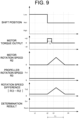
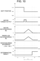
- FIGS. 7 to 10 an example of the abnormality determination process performed in the determination period in which the actuator 34 is shifted from the low position to the neutral position is illustrated.
- the actuator 34 is switched from the low position to the neutral position.
- the engine controller 22 first activates the engine 31 while the first clutch 331 is in the block state.
- FIGS. 7 to 10 are timing charts illustrating detection positions (shift positions) of the actuator 34, torque outputs of the motor 32, the rotation speeds R2 of the motor 32, the rotation speeds R3 of (the propeller of) the propulsive force generator 4, absolute values of the difference (rotation speed difference) between the rotation speeds R2 and R3, and determination results of the abnormality determination process in order from the top.
- the actuator 34 is in a normal state.
- an operation for shifting the actuator 34 from the low position to the neutral position (operation for switching the operation mode) is performed at a time point t1, and a detection position of the actuator 34 is changed from the low position (Low) to the neutral position (Ntrl) at a time point t2.
- the rotation speed R3 of (the propeller of) the propulsive force generator 4 is equal to or higher than the threshold value Th1, the additional control is not executed.
- the rotation speed R2 of the motor 32 is gradually reduced from the time point t2 at which the actuator 34 is switched to the neutral position.
- the actuator 34 is in an abnormality state. Otherwise, conditions are the same as those illustrated in FIG. 7 .
- the second clutch 332 is not switched from the second transmission state to the block state at the time point t2 due to an abnormality of the actuator 34, and therefore, the motor 32 rotates with (the propeller of) the propulsive force generator 4 and the rotation speed R2 of the motor 32 is not reduced.
- the actuator 34 is in a normal state.
- an operation for shifting the actuator 34 from the low position to the neutral position (operation for switching the operation mode) is performed at the time point t1, and a detection position of the actuator 34 is changed from the low position (Low) to the neutral position (Ntrl) at time point t2.
- the additional control is executed by the additional controller 26 on at least one of the comparison targets so that the rotation speed difference between the comparison targets is increased.
- the additional controller 26 increases a torque output instruction value of the motor 32 only in an additional control period T2, and gradually increases the rotation speed R2 of the motor 32 from the time point t2 when the actuator 34 is switched to the neutral position.
- the abnormality determination processor 25 determines an abnormality of the actuator 34 in the determination period within the predetermined period of time after a time point when the actuator 34 drives the power transmitter 33.
- an absolute value of a difference between the rotation speeds R2 and R3 is substantially 0 (zero) even after the time point t2. Therefore, the state in which the rotation speed difference is equal to or less than the determination threshold value Th2 continues for the predetermined period of time T1 or more in the determination period, and accordingly, the abnormality determination processor 25 determines that switching of the second clutch 332 to the block state has failed at the time when the predetermined period of time T1 has elapsed and determines that the actuator 34 is in an "abnormality" state (Err).
- the actuator 34 is in a normal state.
- an operation for shifting the actuator 34 from the high position to the neutral position is performed at the time point t1
- a detection position of the actuator 34 is shifted from the high position (High) to the neutral position (Ntrl) at the time point t2.
- the abnormality determination processor 25 determines an abnormality of the actuator 34 in the determination period within the predetermined period of time after the actuator 34 drives the power transmitter 33, that is, the determination period from the time point t2 when the detection position of the actuator 34 is changed to the time point t4 when the predetermined period of time has elapsed.
- the difference between the rotation speeds R1 and R2 exceeds the determination threshold value Th2 at the time point t3 after the time point t2.
- the abnormality determination processor 25 determines that switching of the second clutch 332 to the block state has been successfully performed, and determines "No Abnormality" (Norm) for the actuator 34.
- the ship control system 2 determines whether the mode switching processor 21 has performed an operation of switching the operation mode (S1). When the operation of switching the operation mode has been performed (S1: Yes), the ship control system 2 proceeds to step S2. On the other hand, when the operation of switching the operation mode has not been performed (S 1: No), the ship control system 2 performs step S1 again.
- step S2 the ship control system 2 drives the actuator 34 in accordance with the switching of the operation mode.
- the abnormality determination processor 25 of the ship control system 2 sets an abnormality determination flag over the determination period, and even when the shift of the actuator 34 is completed during the setting of the abnormality determination flag, a shift to the next operation is prohibited until the abnormality determination process is completed.
- step S3 the additional controller 26 of the ship control system 2 determines whether the additional control is to be performed.
- step S4 in a case where the actuator 34 is driven from the low position to the neutral position, when the rotation speed R3 of (the propeller of) the propulsive force generator 4 is smaller than the threshold value Th1, the additional controller 26 determines that the additional control is required (S3: Yes), and the process proceeds to step S4.
- the additional controller 26 determines that the additional control is not required (S3: No), and the process proceeds to step S5 after step S4 is skipped.
- step S4 when the actuator 34 is driven from the high position to the neutral position (S3: Yes), the additional controller 26 unconditionally determines that additional control is required, and the process proceeds to step S4.
- step S4 the additional controller 26 executes the additional control.
- the content of the additional control is determined on the condition that the motor 32 is not excessively rotated when the actuator 34 is in the neutral position, the propeller is not excessively moved when the actuator 34 is in the low position, and the engine is not reversely rotated when the actuator 34 is in the high position.
- a torque or a rotation speed for the additional control is preferably set taking both a case where an abnormality has occurred and a case where an abnormality has not occurred into consideration.
- the additional control of the motor 32 is set such that an output is in a range in which an abnormality is not erroneously detected due to a rotation speed difference between the comparative targets being equal to or larger than a certain value and the motor 32 does not rotate abnormally.
- the additional control of the motor 32 is set such that an output is in a range in which a device to which the motor 32 is connected is not broken and the hull 1 is not moved.
- step S5 the comparison processor 24 of the ship control system 2 compares rotation speeds of the comparison targets, and the abnormality determination processor 25 determines whether the rotation speeds of the comparison targets are substantially the same as each other.
- the abnormality determination processor 25 determines that the shift to the block state of the second clutch 332 has failed and determines "Abnormality” in the actuator 34 (S6).
- the abnormality determination processor 25 determines that the shift to the block state of the second clutch 332 has been successfully performed and determines "No Abnormality" (Normal) for the actuator 34 (S7).
- a determination result of the abnormality determination processor 25 is displayed for the user by being displayed on the display device, for example.
- the ship control system 2 in the present disclosure includes the computer system.
- the computer system is mainly configured by one or more processors and one or more memories as hardware.
- the processor executes programs that are stored in the memory of the computer system, the functions as the ship control system 2 in the present disclosure are implemented.
- the program may be recorded in advance in the memory of the computer system, may be provided through an electric communication line, or may be provided by being recorded in a non-transitory recording medium, such as a memory card, an optical disk, or a hard disk drive, that is readable by the computer system.
- some or all of the functional sections included in the ship control system 2 may be configured by an electronic circuit.
- the ship control system 2 may not necessarily be configured such that at least some of the functions of the ship control system 2 are integrated in a single housing, and the components of the ship control system 2 may be distributed in a plurality of housings.
- the functions that are distributed in the plurality of devices (for example, the ship control system 2 and the operation device 5) in the first embodiment may be integrated in a single casing.
- the ship control system 2 is not limited to being installed on the hull 1, but may be installed separately from the hull 1.
- the ship control system 2 when the ship control system 2 is embodied by a server device provided separately from the hull 1, a communication between the server device and (communicator of) the hull 1 enables control of the ship 10 (hull 1) by the ship control system 2.
- At least some of the functions of the ship control system 2 may be realized by a cloud (cloud computing) or the like.
- the ship 10 is not limited to the pleasure boat, and may be a commercial ship, such as a cargo ship or a passenger ship, a workboat, such as a tugboat or a salvage boat, a special ship, such as a meteorological observation ship or a training ship, a fishing ship, a naval ship, or the like. Furthermore, the ship 10 is not limited to the ship of the manned type boarded by the operator, and may be an unmanned type ship that can be remotely operated by a person (operator) or autonomously operated.
- the engine 31 is not limited to the diesel engine but may be an engine other than the diesel engine, for example.
- the motor 32 is also not limited to the AC motor and may be a DC motor.
- the motor 32 may be driven by electric power supplied from an electric power generation apparatus, such as a fuel buttery or a solar power generation apparatus.
- the ship 10 at least includes the plurality of power sources including the engine 31 and the motor 32 in the hull 1, and may include three or more power sources including a third power source in addition to the engine 31 and the motor 32.
- the “comparison targets” are at least two of the first power source, the second power source, and the propulsive force generator 4, and not limited to a pair of the second power source and the propulsive force generator 4 or a pair of the first power source and the second power source.
- the “comparison targets” may be at least a pair of the first power source and the propulsive force generator 4 or a combination of three, that is, the first power source, the second power source, and the propulsive force generator 4.
- the six operation modes as the operation mode are not essential configurations for the ship control system 2.
- the two operation modes of the hybrid propulsion mode (low speed) and the hybrid propulsion mode (high speed) may be omitted.
- the switching of the operation mode may not be performed in accordance with a switching operation performed by the user (operator).
- the mode switching processor 21 of the ship control system 2 may automatically switch the operation mode in accordance with a navigation situation of the hull 1 including a current position or a ship speed of the hull 1, a remaining capacity of the main power source 71, or the like.
- the main power source 71 is not limited to the lithium battery, and the auxiliary power source 72 is not limited to a lead battery.
- the main power source 71 is not limited to a chargeable secondary battery and may be a power generation apparatus, such as a fuel battery or a solar power generation apparatus.
- a ship control program that causes at least one processor to execute the method for controlling a ship according to any one of Appendices 1 to 10.
Landscapes
- Chemical & Material Sciences (AREA)
- Engineering & Computer Science (AREA)
- Combustion & Propulsion (AREA)
- Mechanical Engineering (AREA)
- Ocean & Marine Engineering (AREA)
- Control Of Vehicle Engines Or Engines For Specific Uses (AREA)
Abstract
Description
- The present disclosure relates to a method for controlling a ship including a plurality of power sources, a ship control program, a ship control system, and a ship.
- According to a related art, as a method for controlling a ship including a plurality of power sources, such as an engine and a motor, a method for performing switching among a plurality of operation modes including a mode for propulsion by an engine, a mode for propulsion by a motor, a mode for propulsion by an engine and a motor, and an electric power generation mode from one to another has been used (refer to
Patent Document 1, for example). - Ships according to the related art include, in addition to a plurality of power sources, a power transmitter, an outputter, and an actuator. The power transmitter transmits power from at least one of the plurality of power sources to the outputter including a propeller to generate a propulsive force of a hull. The actuator serving as a shifter switches a connection state of the power transmitter by driving a clutch included in the power transmitter, such as a meshing type clutch including a dog clutch, for example, so as to perform switching among the plurality of operation modes.
- Patent Document 1:
Japanese Unexamined Patent Application Publication No. 2023-037810 - As with the related art described above, in the configuration in which the power transmitter is driven by the actuator, an operation mode in the plurality of propulsion modes is specified based on an operation state of the actuator. Therefore, for example, when an abnormality occurs in the actuator due to a failure of the actuator or the like, a management state of the operation mode may deviate from an actual operation mode.
- An object of the present disclosure is to provide a method for controlling a ship, a ship control program, a ship control system, and a ship which can improve reliability of a management state of an operation mode.
- A method for controlling a ship according to an aspect of the present disclosure is employed in a ship that has a plurality of power sources including a first power source and a second power source and that propels a hull by transmitting power from at least one of the plurality of power sources through a power transmitter to a propulsive force generator. The method includes determining at least two of the first power source, the second power source, and the propulsive force generator as comparison targets and comparing rotation speeds of the comparison targets with each other, and determining an abnormality of at least one of an actuator that drives the power transmitter and the power transmitter based on a result of the comparison between the rotation speeds.
- A ship control program according to another aspect of the present disclosure causes at least one processor to execute the method for controlling a ship.
- The method for controlling a ship is employed in a ship that has a plurality of power sources including a first power source and a second power source and that propels a hull by transmitting power from at least one of the plurality of power sources through a power transmitter to a propulsive force generator. The ship control system includes a comparison processor and an abnormality determination processor. The comparison processor determines at least two of the first power source, the second power source, and the propulsive force generator as comparison targets, and compares rotation speeds of the comparison targets with each other. The abnormality determination processor determines an abnormality of at least one of the actuator that drives the power transmitter and the power transmitter based on a result of the comparison between the rotation speeds.
- A ship according to still another aspect of the present disclosure includes the ship control system and the hull.
- According to the present disclosure, a method for controlling a ship, a ship control program, a ship control system, and a ship that can improve reliability of a management state of an operation mode are provided.
-
-
FIG. 1 is an appearance view schematically illustrating a configuration of a ship according to a first embodiment. -
FIG. 2 is a block diagram schematically illustrating the configuration of the ship according to the first embodiment. -
FIG. 3 is a diagram schematically illustrating a driving unit of the ship according to the first embodiment. -
FIG. 4 is a diagram schematically illustrating a state of the driving unit in a motor propulsion mode and an engine propulsion mode of the ship according to the first embodiment. -
FIG. 5 is a diagram schematically illustrating a state of the driving unit in an electric power generation mode of the ship according to the first embodiment. -
FIG. 6 is a diagram schematically illustrating a state of the driving unit in a hybrid propulsion mode of the ship according to the first embodiment. -
FIG. 7 is a timing chart illustrating a concrete example of an abnormality determination process of a ship control system according to the first embodiment. -
FIG. 8 is a timing chart illustrating a concrete example of an abnormality determination process of the ship control system according to the first embodiment. -
FIG. 9 is a timing chart illustrating a concrete example of an abnormality determination process of the ship control system according to the first embodiment. -
FIG. 10 is a timing chart illustrating a concrete example of an abnormality determination process of the ship control system according to the first embodiment. -
FIG. 11 is a timing chart illustrating a concrete example of an abnormality determination process of the ship control system according to the first embodiment. -
FIG. 12 is a timing chart illustrating a concrete example of an abnormality determination process of the ship control system according to the first embodiment. -
FIG. 13 is a flowchart illustrating an operation example of the ship control system according to the first embodiment. - Hereinafter, embodiments of the present disclosure will be described with reference to the accompanying drawings. The following embodiments are each one example that embodies the present disclosure, and are not intended to limit the technical scope of the present disclosure.
- First, an entire configuration of a
ship 10 according to this embodiment will be described with reference toFIGS. 1 and2 . - The
ship 10 is a moving body that sails (navigates) on water, such as ocean, lake, or river. As an example in this embodiment, theship 10 is a "pleasure boat" that is a small-sized ship mainly used for sport, recreation, or the like. Furthermore, according to this embodiment, theship 10 is operated in accordance with an operation (including a remote operation) performed by a person (an operator), and in particular, theship 10 is of a manned type that can be boarded by the person as the operator. - The
ship 10 includes ahull 1, apower source device 7, and aship control system 2 as illustrated inFIG. 1 . Thehull 1 includes adriving unit 3 that generates power, apropulsive force generator 4 that outputs a propulsive force for propelling thehull 1, and anoperation device 5 that accepts an operation performed by a person (operator). In addition, thehull 1 further includes various onboard facilities including a rudder mechanism, a communication device, and a lighting facility. - The
driving unit 3 includes, as illustrated inFIG. 2 , anengine 31 serving as a first power source, amotor 32 serving as a second power source, and apower transmitter 33. Thepropulsive force generator 4 including a propeller in this embodiment receives dynamic power generated by thedriving unit 3 and rotates the propeller around a rotation shaft (propeller shaft), to thereby generate the propulsive force to move thehull 1 forward or rearward. - The plurality of power sources including the first power source (engine 31) and the second power source (motor 32) individually generate power (mechanical energy) to be used for propelling the
hull 1. The plurality of power sources have different output characteristics from each other, and have at least different maximum outputs (maximum rotation speeds and maximum torques). In this embodiment, the plurality of power sources are completely different types of power source employing different methods. In short, theship 10 according to this embodiment includes thehybrid driving unit 3 having the plurality of types of power source. - In this embodiment, the first power source is the engine (internal combustion engine) 31 that generates power by burning of fuel and the second power source is the motor (electric motor) 32 that generates power by supplied electric power (electric energy). More specifically, the
engine 31 is a diesel engine that is driven with light oil as fuel, and themotor 32 is an AC motor driven by AC power. - The
engine 31 and themotor 32 are individually driven and individually generate power. Therefore, the plurality of power sources can be switched among, for example, a state in which only theengine 31 between theengine 31 and themotor 32 is driven, a state in which only themotor 32 is driven, and a state in which both theengine 31 and themotor 32 are driven. Here, the power generated by theengine 31 and the power generated by themotor 32 are combined by thepower transmitter 33, and the combined power is supplied to thepropulsive force generator 4. Therefore, since the power of theengine 31 is combined with the power of themotor 32, themotor 32 can assist theengine 31 so that thepropulsive force generator 4 is driven by a larger power. - The
power transmitter 33 is disposed between the plurality of power sources (engine 31 and motor 32) and thepropulsive force generator 4. Thepower transmitter 33 has a function of receiving power generated by the plurality of power sources as inputs and transmitting the power to thepropulsive force generator 4. Here, thepower transmitter 33 combines power supplied from the plurality of power sources (engine 31 and motor 32) and outputs the combined power to thepropulsive force generator 4. - Furthermore, the
power transmitter 33 has a function of determining whether power is to be transmitted from the plurality of power sources (engine 31 and motor 32) to thepropulsive force generator 4, that is, a function of performing switching between a "transmission state" and a "block state" from one to another. The term "transmission state" in the present disclosure indicates a state in which the plurality of power sources (engine 31 and motor 32) and thepropulsive force generator 4 are mechanically connected to each other and power is transmitted from the power sources to thepropulsive force generator 4. When the power sources (engine 31 and motor 32) are driven in the transmission state of thepower transmitter 33, thepropulsive force generator 4 is driven by the power generated by the power sources. The term "block state" in the present disclosure indicates a state in which the power sources (engine 31 and motor 32) and thepropulsive force generator 4 are mechanically disconnected from one another so that power is not transmitted from the power sources to thepropulsive force generator 4. Since power generated by the power sources is not transmitted to thepropulsive force generator 4 even when the power sources (engine 31 and motor 32) are driven in the block state of thepower transmitter 33, thepropulsive force generator 4 is not driven. - The
power transmitter 33 further has a function of switching a coupling state between the plurality of power sources (engine 31 and motor 32). Specifically, thepower transmitter 33 has a function of performing switching between a coupling state" in which the first power source (engine 31) and the second power source (motor 32) are mechanically coupled with each other and an "independent state" in which the first power source (engine 31) and the second power source (motor 32) are disconnected from each other. The term "connection state" in the present disclosure indicates a state in which the first and second power sources are mechanically connected to each other so that power is transmitted between the first and second power sources. When the first power source (engine 31) is driven in the coupled state of thepower transmitter 33, for example, the second power source (motor 32) is driven by power generated by the first power source (engine 31) and the second power source may be used as an electric power generator to generate electric power. The term "independent state" in the present disclosure indicates a state in which the first and second power sources are mechanically disconnected from each other so that power is not transmitted between the first and second power sources. In the independent state of thepower transmitter 33, even when the first power source (engine 31) is driven, the second power source (motor 32) does not generate electric power. - The driving
unit 3 will be described in detail in a section of "2. Configuration of Driving Unit". - The
ship control system 2 mainly includes a computer system having one or more processors, such as a central processing unit (CPU), and one or more memories, such as a read only memory (ROM) and a random access memory (RAM), and performs various types of processing (information processing). A program (ship control program) for causing at least one processor to execute a control method of theship 10 is recorded in the one or more memories in theship control system 2. Theship control system 2 is the computer system mounted on thehull 1 as an example of this embodiment. - The
ship control system 2 at least controls the drivingunit 3. That is, theship control system 2 controls, for example, driving states of theengine 31 and themotor 32 and a state of the power transmitter 33 (transmission state/block state, coupling state/independent state, and the like). - In this embodiment, the
ship control system 2 is electrically connected to theoperation device 5, and controls the drivingunit 3 and the like in accordance with an operation signal supplied from theoperation device 5. For example, theship control system 2 controls the drivingunit 3 in accordance with an operation signal supplied from theoperation device 5 so as to rotate the propeller of thepropulsive force generator 4 to thereby move thehull 1 forward and rearward. Furthermore, theship control system 2 can adjust a rotation speed of the propeller of thepropulsive force generator 4 by controlling an output (rotation speed or torque) of theengine 31 or themotor 32 so as to adjust a movement speed (ship speed) of thehull 1. - Moreover, the
ship control system 2 can switch a plurality of operation modes from one to another. In the present disclosure, the term "operation mode" represents various modes of different connection states (transmission state/block state, coupling state/independent state, and the like) of thepower transmitter 33, and includes, for example, modes of different power sources to be used for propelling thehull 1 among the plurality of power sources (engine 31 and motor 32). Specifically, in theship control system 2, a plurality of operation modes can be switched from one to another by performing switching among the connection states of thepower transmitter 33. - In this embodiment, the plurality of operation modes include a motor propulsion mode, an engine propulsion mode, an electric power generation mode, and a hybrid propulsion mode. In the motor propulsion mode, only the
motor 32, between theengine 31 and themotor 32, is used for propelling thehull 1. In the engine propulsion mode, only theengine 31, between theengine 31 and themotor 32, is used for propelling thehull 1. In the electric power generation mode, themotor 32 is driven by power generated by theengine 31 and themotor 32 generates electric power as an electric power generator. In the hybrid propulsion mode, both the engine 31 (first power source) and the motor 32 (second power source) are used for propelling thehull 1. - In this embodiment, the
ship control system 2 is an integrated controller that controls theentire hull 1, and includes an electronic control unit (ECU), for example. However, theship control system 2 may be disposed separately from the integrated controller. A detailed description will be made on theship control system 2 in a section "3. Configuration of Ship Control System". - The
operation device 5 is a user interface that accepts an operation performed by a person (operator) and is installed in an operation room where the operator boards in thehull 1. Theoperation device 5 accepts various operations performed by the operator and outputs electric signals (operation signals) corresponding to the operations to theship control system 2. As one example in this embodiment, theoperation device 5 includes anoperation section 51 including an operation lever which is operated in a swingable manner (refer toFIG. 2 ). Theoperation device 5 including a detector, such as an encoder that detects a position (rotation angle) of theoperation section 51, detects an operation amount of theoperation section 51 in accordance with a position of theoperation section 51 and outputs an operation signal indicating the operation amount. Furthermore, theoperation device 5 may further include a plurality of mechanical switches, a touch panel, and an operation dial. - The display device is a user interface that outputs various types of information for a person (operator) and is installed in the operation room where the operator boards in the
hull 1, for example. The display device is electrically connected to theship control system 2, for example, and displays various screens in accordance with a display control signal supplied from theship control system 2. - The
power source device 7 supplies electric power to onboard loads including themotor 32 and a starter for starting theengine 31, and various onboard devices. The term "electric power" referred to in the present disclosure includes both AC power and DC power. As illustrated inFIG. 2 , thepower source device 7 includes amain power source 71 and anauxiliary power source 72. Themain power source 71 supplies electric power for driving to at least themotor 32 as a power source. On the other hand, theauxiliary power source 72 supplies electric power to at least the starter and so on. - The
main power source 71 is a secondary battery (storage battery) of a large capacity, such as a lithium ion battery. Theauxiliary power source 72 is a secondary battery (storage battery), such as a lead battery. As described above, thepower source device 7 includes the two types of chargeable power source (battery), and themain power source 71 as a main battery has a larger capacity and a larger output than theauxiliary power source 72 as an auxiliary battery. - In the operation room, a communication device and the like are also installed. The communication device is communicable with another system (including a server) outside the
hull 1 and can exchange data with the other system. - Next, a detailed description will be made on a configuration of the
driving unit 3 with reference toFIGS. 3 to 6 . - The driving
unit 3 includes, as described above, the plurality of power sources (engine 31 and motor 32) and thepower transmitter 33. Furthermore, the drivingunit 3 further includes anactuator 34 and adriving circuit 351 as illustrated inFIG. 3 . InFIG. 3 and so on, the electrical connection relationship between the drivingcircuit 351 and themain power source 71 is indicated by a dotted line. - In this embodiment, the
engine 31 which is a diesel engine has a combustion room segmented by cylinders or the like, and a piston is reciprocated when fuel (light oil) burns in the combustion room. Theengine 31 has a crankshaft which rotates in accordance with the reciprocation of the piston as an output shaft, and the crankshaft is connected to thepower transmitter 33. Thus, power is input from theengine 31 to thepower transmitter 33 through the crankshaft. - In this embodiment, the
motor 32 which is an AC motor is driven by AC power (AC voltage) supplied from the drivingcircuit 351 constituted by an inverter circuit. The drivingcircuit 351 is electrically connected to themain power source 71, and converts a DC voltage output from themain power source 71 to an AC voltage to be supplied to themotor 32 to thereby drive themotor 32. The output shaft of themotor 32 is connected to thepower transmitter 33, and power is supplied to thepower transmitter 33 from themotor 32 through the output shaft. - Furthermore, in this embodiment, the driving
circuit 351 is a bidirectional inverter circuit, and has a function of converting an AC voltage into a DC voltage in addition to a function of converting a DC voltage into an AC voltage. Therefore, the drivingcircuit 351 is capable of not only converting a DC voltage output from themain power source 71 into an AC voltage and outputting the AC voltage to themotor 32 but also converting an AC voltage output from themotor 32 into a DC voltage and outputting the DC voltage to themain power source 71. That is, in thedriving unit 3 according to this embodiment, since themotor 32 is used as an electric power generator, themain power source 71 can be charged by the drivingcircuit 351 by using electric energy (AC power) generated when themotor 32 is rotated by an external force. Thus, the drivingcircuit 351 also functions as a charging circuit that charges themain power source 71 with a regenerative current of themotor 32. - In this embodiment, the
power transmitter 33 includes, as illustrated inFIG. 3 , afirst clutch 331, asecond clutch 332, afirst gear 333, asecond gear 334, athird gear 335, and afourth gear 336. Although the configuration of thepower transmitter 33 is simplified inFIG. 3 and so on, thefirst gear 333, thesecond gear 334, thethird gear 335, and thefourth gear 336 are included in a deceleration device as a marine gear. - The
first clutch 331 is inserted between the output shaft (crankshaft) of theengine 31 and thepropulsive force generator 4. That is, thefirst clutch 331 is located in course of a power transmission path extending from theengine 31 to thepropulsive force generator 4. Thefirst clutch 331 includes an input-side rotator 331A and an output-side rotator 331B, and is configured to be switchable between a state in which the input-side rotator 331A and the output-side rotator 331B are connected to each other (transmission state) and a state in which the input-side rotator 331A and the output-side rotator 331B are disconnected from each other (block state). - The input-
side rotator 331A is connected to the output shaft (crankshaft) of theengine 31, and the output-side rotator 331B is connected to thepropulsive force generator 4. Thus, the input-side rotator 331A is rotated by the power generated by theengine 31. When thefirst clutch 331 is in the transmission state, the power of theengine 31 is transmitted to thepropulsive force generator 4 via thefirst clutch 331, whereas when thefirst clutch 331 is in the block state, the power of theengine 31 is blocked by thefirst clutch 331 and is not transmitted to thepropulsive force generator 4. - The
first clutch 331 is constituted by a hydraulic clutch, such as a wet multiple disk clutch, as an example, and performs switching between the transmission state and the block state when hydraulic oil is supplied from a hydraulic circuit including a hydraulic pump. The switching between the transmission state and the block state of thefirst clutch 331 is performed when theship control system 2 controls a solenoid valve of the hydraulic circuit. Specifically, theship control system 2 directly or indirectly controls the first clutch 331 so that thefirst clutch 331 is switched between the transmission state and the block state. - The
first gear 333 is connected to the input-side rotator 331A of thefirst clutch 331 and rotates in accordance with rotation of the input-side rotator 331A. Thesecond gear 334 is disposed to be meshed with thefirst gear 333 and is rotated together with thefirst gear 333 . Thethird gear 335 is connected to the output-side rotator 331B of thefirst clutch 331 and rotates in accordance with rotation of the output-side rotator 331B. Thefourth gear 336 is disposed to be meshed with thethird gear 335 and is rotated together with thethird gear 335. - The
second clutch 332 is inserted between the output shaft of themotor 32 and the second andfourth gears second clutch 332 is located in course of a power transmission path extending from themotor 32 to thepropulsive force generator 4. Thesecond clutch 332 includes a motor-side rotator 332C and counterpart-side rotators side rotator 332C and the counterpart-side rotators side rotator 332C and the counterpart-side rotators - In this embodiment, as the counterpart-
side rotators side rotator 332A and a second counterpart-side rotator 332B are disposed. Thesecond clutch 332 can perform switching among a first transmission state in which the motor-side rotator 332C is connected to the first counterpart-side rotator 332A, a second transmission state in which the motor-side rotator 332C is connected to the second counterpart-side rotator 332B, and a block state in which the motor-side rotator 332C is disconnected from both the first and second counterpart-side rotators - The motor-
side rotator 332C is connected to the output shaft of themotor 32. The first counterpart-side rotator 332A is connected to thesecond gear 334, and the second counterpart-side rotator 332B is connected to thefourth gear 336. Thus, the motor-side rotator 332C is rotated when receiving power generated by themotor 32. Then, when thesecond clutch 332 is in the first transmission state, the power of themotor 32 is transmitted to the input-side rotator 331A of the first clutch 331 through thesecond clutch 332, thesecond gear 334 and thefirst gear 333 on a high-speed side. Here, when thefirst clutch 331 is in the transmission state, the power of themotor 32 is combined with the power of theengine 31 and the combined power is transmitted to thepropulsive force generator 4 via thefirst clutch 331. Furthermore, when thesecond clutch 332 is in the second transmission state, the power of themotor 32 is transmitted to thepropulsive force generator 4 through thesecond clutch 332, thefourth gear 336 and thethird gear 335 on a low-speed side. On the other hand, when thesecond clutch 332 is in the block state, the power of themotor 32 is blocked by thesecond clutch 332 and is not transmitted to thepropulsive force generator 4. - The
second clutch 332 is a mesh clutch, such as a dog clutch, as an example. The switching of thesecond clutch 332 among the first transmission state, the second transmission state, and the block state is performed by shifting the motor-side rotator 332C by theactuator 34 constituted by a shifter. Theactuator 34 shifts the motor-side rotator 332C to a position where the motor-side rotator 332C is meshed with the first counterpart-side rotator 332A, so as to bring thesecond clutch 332 to the first transmission state in which the motor-side rotator 332C is meshed with the first counterpart-side rotator 332A. Furthermore, theactuator 34 shifts the motor-side rotator 332C to a position where the motor-side rotator 332C is meshed with the second counterpart-side rotator 332B, so as to bring thesecond clutch 332 to the second transmission state in which the motor-side rotator 332C is meshed with the second counterpart-side rotator 332B. Theactuator 34 shifts the motor-side rotator 332C to a position where the motor-side rotator 332C is not meshed with the first counterpart-side rotator 332A or the second counterpart-side rotator 332B, so as to bring thesecond clutch 332 to the block state. - It is assumed, in the present disclosure, that a position of the shifter (actuator 34) when the motor-
side rotator 332C is meshed with the first counterpart-side rotator 332A so that thesecond clutch 332 is brought to the first transmission state is defined as a "high position". Similarly, it is assumed that a position of the shifter (actuator 34) when the motor-side rotator 332C is meshed with the second counterpart-side rotator 332B so that thesecond clutch 332 is brought the second transmission state is defined as a "low position". Furthermore, it is assumed that a position of the shifter (actuator 34) when the motor-side rotator 332C is not meshed with the first counterpart-side rotator 332A or the second counterpart-side rotator 332B so that thesecond clutch 332 is brought to the block state is defined as a "neutral position". - The switching between the first transmission state, the second transmission state, and the block state of the
second clutch 332 is performed when theship control system 2 controls themotorized actuator 34, for example. Specifically, theship control system 2 directly or indirectly controls thesecond clutch 332 so that thesecond clutch 332 is switched between the transmission state (first transmission state or second transmission state) and the block state. - According to the
driving unit 3 configured as described above, theship control system 2 controls the first andsecond clutches FIGS. 4 to 6 . InFIGS. 4 to 6 , states of thedriving unit 3 in the individual operation modes are schematically illustrated, and the drivingcircuit 351 and the like are not illustrated. Furthermore, power transmitted from theengine 31 and themotor 32 to thepropulsive force generator 4 is represented by (bold) dotted lines, inFIGS. 4 to 6 . - An upper half in
FIG. 4 indicates the motor propulsion mode to be used when only themotor 32 between theengine 31 and themotor 32 is used for propelling thehull 1. In the motor propulsion mode, theship control system 2 performs control such that thefirst clutch 331 is brought to the block state and thesecond clutch 332 is brought to the second transmission state. Furthermore, in the motor propulsion mode, theship control system 2 controls the drivingcircuit 351 to stop theengine 31 and drive themotor 32 with electric power supplied from themain power source 71. Accordingly, as illustrated inFIG. 4 , power generated by themotor 32 is transmitted to thepropulsive force generator 4 through thesecond clutch 332, thefourth gear 336, and thethird gear 335 to rotate the propeller of thepropulsive force generator 4 so that propulsive force for thehull 1 can be generated. - A lower half in
FIG. 4 indicates an engine propulsion mode to be used when only theengine 31 between theengine 31 and themotor 32 is used for propelling thehull 1. In the engine propulsion mode, theship control system 2 performs control such that thefirst clutch 331 is brought to the transmission state and thesecond clutch 332 is brought to the block state. Furthermore, in the engine propulsion mode, theship control system 2 controls the drivingcircuit 351 to drive theengine 31 and stop themotor 32. By this, as illustrated inFIG. 4 , power generated by theengine 31 is transmitted to thepropulsive force generator 4 through the first clutch 331 to rotate the propeller of thepropulsive force generator 4 so that propulsive force for thehull 1 can be generated. - An upper half in
FIG. 5 indicates an "electric power generation mode (sailing)" which is a sailing state of thehull 1 in electric power generation modes in which electric power is generated by themotor 32 using power generated by theengine 31. In the electric power generation mode (sailing), theship control system 2 performs control such that thefirst clutch 331 is brought to the transmission state and thesecond clutch 332 is brought to the first transmission state. Furthermore, in the electric power generation mode (sailing), theship control system 2 drives theengine 31. By this, as illustrated inFIG. 5 , power generated by theengine 31 is transmitted to thepropulsive force generator 4 through the first clutch 331 to rotate the propeller of thepropulsive force generator 4 so that propulsive force for thehull 1 is generated. Furthermore, the power generated by theengine 31 is also transmitted (distributed) to themotor 32 through thefirst gear 333, thesecond gear 334, and thesecond clutch 332 to rotate the output shaft of themotor 32 so as to cause themotor 32 to generate AC power. AC power generated in themotor 32 is used by the drivingcircuit 351 constituted by the bidirectional inverter circuit for charging themain power source 71. - A lower half in
FIG. 5 indicates an "electric power generation mode (anchoring)" which is an anchoring state (anchorage) of thehull 1 in the electric power generation modes in which electric power is generated by themotor 32 using power generated by theengine 31. In the electric power generation mode (anchoring), theship control system 2 performs control such that thefirst clutch 331 is brought to the block state and thesecond clutch 332 is brought to the first transmission state. Furthermore, in the electric power generation mode (anchoring), theship control system 2 drives theengine 31. By this, as illustrated inFIG. 5 , the power generated by theengine 31 is transmitted to themotor 32 through thefirst gear 333, thesecond gear 334, and thesecond clutch 332 to rotate the output shaft of themotor 32 so as to cause themotor 32 to generate AC power. The AC power generated in themotor 32 is used by the drivingcircuit 351 constituted by the bidirectional inverter circuit for charging themain power source 71. - An upper half in
FIG. 6 indicates a "hybrid propulsion mode (low speed)", which is suitable for sailing at "low speed", in hybrid propulsion modes to be used when both theengine 31 and themotor 32 are used for propelling thehull 1. In the hybrid propulsion mode (low speed), theship control system 2 performs control such that thefirst clutch 331 is brought to the transmission state and thesecond clutch 332 is brought to the second transmission state. Furthermore, in the hybrid propulsion mode (low speed), theship control system 2 drives theengine 31 and controls the drivingcircuit 351 to drive themotor 32 with electric power supplied from themain power source 71. By this, as illustrated inFIG. 5 , power generated by theengine 31 is transmitted to thepropulsive force generator 4 through thefirst clutch 331 and power generated by themotor 32 is transmitted to thepropulsive force generator 4 through thesecond clutch 332, thefourth gear 336, and thethird gear 335. Consequently, the power generated by theengine 31 and the power generated by themotor 32 are combined with each other, the propeller of thepropulsive force generator 4 is rotated, and the propulsive force for thehull 1 is generated. - A lower half in
FIG. 6 indicates a "hybrid propulsion mode (high speed)", which is suitable for navigation at "high speed", in the hybrid propulsion modes to be used when both theengine 31 and themotor 32 are used for propulsion of thehull 1. In the hybrid propulsion mode (high speed), theship control system 2 performs control such that thefirst clutch 331 is brought to the transmission state and thesecond clutch 332 is brought to the first transmission state. Furthermore, in the hybrid propulsion mode (high speed), theship control system 2 drives theengine 31 and controls the drivingcircuit 351 to drive themotor 32 with electric power supplied from themain power source 71. By this, as illustrated inFIG. 5 , power generated by theengine 31 is transmitted to thepropulsive force generator 4 through thefirst clutch 331 and power generated by themotor 32 is transmitted to thepropulsive force generator 4 through thesecond clutch 332, thesecond gear 334, thefirst gear 333, and thefirst clutch 331. Consequently, the power generated by theengine 31 and the power generated by themotor 32 are combined with each other, the propeller of thepropulsive force generator 4 is rotated, and the propulsive force for thehull 1 is generated. - Furthermore, in the motor propulsion mode in the upper half in
FIG. 4 , at a time of sailing of thehull 1, themain power source 71 may be charged by supplying rotation force of the propeller of thepropulsive force generator 4 as regenerative energy to themain power source 71. In this case, the rotation force of thepropulsive force generator 4 is transmitted to themotor 32 through thethird gear 335, thefourth gear 336, and thesecond clutch 332 to rotate the output shaft of themotor 32 so as to cause themotor 32 to generate AC power. The AC power generated in themotor 32 is used by the drivingcircuit 351 constituted by the bidirectional inverter circuit for charging themain power source 71. - Here, when the
second clutch 332 driven by theactuator 34 as a shifter in thepower transmitter 33 is focused, the six operation modes described above are categorized into three groups. - Specifically, in a first group including the electric power generation mode (navigating), the electric power generation mode (anchoring), and the hybrid propulsion mode (high speed), the
second clutch 332 is controlled to be in the first transmission state. Furthermore, in a second group including the motor propulsion mode and the hybrid propulsion mode (low speed), thesecond clutch 332 is controlled to be in the second transmission state. Moreover, in a third group including the engine propulsion mode, thesecond clutch 332 is controlled to be in the block state. - Therefore, when the motor propulsion mode is shifted to the electric power generation mode (navigating), the
actuator 34 is first shifted from a low position to a neutral position so that the motor-side rotator 332C is shifted from a position where the motor-side rotator 332C is meshed with the second counterpart-side rotator 332B to a position where the motor-side rotator 332C is not meshed with the first counterpart-side rotator 332A or the second counterpart-side rotator 332B. Then theactuator 34 is shifted from the neutral position to a high position so that the motor-side rotator 332C is shifted from the position where the motor-side rotator 332C is not meshed with the first counterpart-side rotator 332A or the second counterpart-side rotator 332B to a position where the motor-side rotator 332C is meshed with the first counterpart-side rotator 332A. - Furthermore, although not illustrated in
FIG. 3 and so on, the drivingunit 3 further includes a hydraulic circuit for driving thefirst clutch 331 and various sensors. - Next, a description will be made on a configuration of the
ship control system 2 according to this embodiment with reference toFIG. 2 . Theship control system 2 is a component of theship 10 and constitutes theship 10 together with thehull 1. That is, theship 10 according to this embodiment includes theship control system 2 and thehull 1. Theship control system 2 is the computer system mounted on thehull 1 as an example of this embodiment. - The
ship control system 2 includes, as illustrated inFIG. 2 , amode switching processor 21, anengine controller 22, and amotor controller 23. Furthermore, as illustrated inFIG. 2 , theship control system 2 further includes acomparison processor 24, anabnormality determination processor 25, and anadditional controller 26. Thecomparison processor 24, theabnormality determination processor 25, and theadditional controller 26 are configured to determine whether at least one of theactuator 34 and thepower transmitter 33 has an abnormality, that is, to determine a normal/abnormality state. - In this embodiment, as an example, the
ship control system 2 has, as the main component, the computer system that has the one or more processors. Accordingly, when the one or more processors execute a ship control program, these plurality of functional sections (themode switching processor 21 and the like) are realized. These plurality of functional sections included in theship control system 2 may be distributed in a plurality of casings or may be provided in a single casing. - The
ship control system 2 is communicable with the devices included in the sections in thehull 1. That is, to theship control system 2, at least the driving circuit 351 (refer toFIG. 3 ) which drives theoperation device 5, the display device, theengine 31, and themotor 32 is connected in a communication available manner. By this, theship control system 2 can control the drivingunit 3 in accordance with an operation signal supplied from theoperation device 5, for example. Furthermore, theship control system 2 can cause the display device to display various types of information, for example. Here, theship control system 2 may directly exchange various types of information (electric signals) with the devices, or may indirectly exchange such information with the devices via a relay or the like. - The
mode switching processor 21 executes a process of switching an operation mode of theship 10. In this embodiment, themode switching processor 21 selects one of the motor propulsion mode, the engine propulsion mode, the electric power generation mode, and the hybrid propulsion mode in accordance with an operation performed by a person (operator) on theoperation device 5. As an example, theoperation device 5 includes a mode selection switch, and when one of the motor propulsion mode, the engine propulsion mode, the electric power generation mode, and the hybrid propulsion mode is selected by the mode selection switch, themode switching processor 21 drives thepower transmitter 33 to perform switching to the selected operation mode. - The
engine controller 22 controls theengine 31 serving as the first power source. Specifically, theengine controller 22 performs control, such as fuel injection and open/close of an exhaust valve, for driving theengine 31. By this, theengine controller 22 can control theengine 31 so that an output (mainly, rotation speed) of theengine 31 becomes an arbitrary value. - The
motor controller 23 controls themotor 32 serving as the second power source. Specifically, themotor controller 23 controls the driving circuit 351 (refer toFIG. 3 ) for driving themotor 32. By this, themotor controller 23 can control themotor 32 so that an output (mainly, rotation speed and torque) of themotor 32 becomes an arbitrary value. In particular, in this embodiment, themotor controller 23 can perform two types of control including control of the number of rotations (rotation speed control) and torque control as the control of themotor 32. In the rotation speed control, themotor controller 23 sets a target rotation speed of themotor 32, and controls a rotation speed of themotor 32 so that the rotation speed becomes close to the target rotation speed. In the torque control, themotor controller 23 sets a target torque of themotor 32, and controls a torque of themotor 32 so that the torque becomes close to the target torque. - The
comparison processor 24 executes a comparison process of comparing rotation speeds of comparison targets. Here, the term "comparison targets" include at least two of the first power source (engine 31), the second power source (motor 32), and thepropulsive force generator 4. Specifically, thecomparison processor 24 determines at least two of theengine 31 serving as the first power source, themotor 32 serving as the second power source, and thepropulsive force generator 4 as the comparison targets, and compares rotation speeds of the at least two (comparison targets). - In this embodiment, the
comparison processor 24 determines two of the first power source (engine 31), the second power source (motor 32), and thepropulsive force generator 4 as comparison targets, and compares rotation speeds of the selected two so as to calculate an absolute value of a difference between the two rotation speeds (rotation speed difference). For example, when the second power source (motor 32) and thepropulsive force generator 4 are determined as the comparison targets, thecomparison processor 24 calculates an absolute value of a difference between a rotation speed R2 of the second power source (motor 32) and a rotation speed R3 of (the propeller of ) the propulsive force generator 4 (R2-R3). Alternatively, when the first power source (engine 31) and the second power source (motor 32) are determined as comparison targets, thecomparison processor 24 calculates an absolute value of a difference between the rotation speed R1 of the first power source (engine 31) and the rotation speed R2 of the second power source (motor 32) (R1-R2). - Here, the rotation speeds of the first power source, the second power source, and (the propeller of) the
propulsive force generator 4 may be acquired using speed meters, for example, by thecomparison processor 24. Therefore, in this embodiment, rotation speed meters are individually disposed for measuring rotation speeds of the first power source, the second power source, and (the propeller of) thepropulsive force generator 4. - The
abnormality determination processor 25 performs an abnormality determination process of determining an abnormality of at least one of theactuator 34 that drives thepower transmitter 33 and thepower transmitter 33. Here, theabnormality determination processor 25 determines an abnormality of at least one of theactuator 34 and thepower transmitter 33 based on a result of the comparison of the rotation speeds performed by thecomparison processor 24. - In this embodiment, the
comparison processor 24 calculates a rotation speed difference between two (comparison targets) of the first power source (engine 31), the second power source (motor 32), and thepropulsive force generator 4 as a result of the comparison of the rotation speeds, and therefore, theabnormality determination processor 25 determines an abnormality based on the calculated rotation speed difference. Furthermore, as an example in this embodiment, theabnormality determination processor 25 determines whether an abnormality has occurred (that is, normal or abnormality) in theactuator 34 that drives thepower transmitter 33. - The
additional controller 26 performs additional control on at least one of the comparison targets. The term "additional control" as used herein refers to control performed on at least one of the comparison targets so as to increase the rotation speed difference between the comparison targets when thecomparison processor 24 compares the rotation speeds. - As an example, in a case where the second power source (motor 32) and the
propulsive force generator 4 are determined as the comparison targets, when the rotation speed R2 of the second power source and the rotation speed R3 of (the propeller of) thepropulsive force generator 4 are both substantially zero, a difference between the rotation speeds (R2-R3) is small. In such a case, theadditional controller 26 can widen (increase) the rotation speed difference (R2-R3) by performing additional control to increase the rotation speed R2 of the second power source. As a result, a result of the comparison between the rotation speeds used for the abnormality determination, that is, the rotation speed difference is emphasized, and the reliability of the abnormality determination in theabnormality determination processor 25 is improved. - An example of a method for controlling the ship 10 (hereinafter, also simply referred to as "control method") executed mainly by the
ship control system 2 will be described hereinafter. - The control method according to this embodiment is executed by the
ship control system 2 that is mainly configured by the computer system, and thus, in other words, is embodied by the ship control program. That is, the ship control program according to this embodiment is a computer program that causes one or more processors to execute processes relating to the method for controlling theship 10. Such a ship control program may be executed by theship control system 2, the terminal device, and the like in cooperation with each other, for example. - Here, when a specific start operation set in advance for executing the ship control program is performed, the
ship control system 2 executes the following various processes relating to the control method. The start operation is, for example, a power-on operation of theship 10. On the other hand, when a specific termination operation set in advance is performed, theship control system 2 terminates the following various processes relating to the control method. The termination operation is, for example, a power-off operation of theship 10. - First, the abnormality determination process of determining an abnormality on at least one of the
actuator 34 and thepower transmitter 33 and processes associated with the abnormality determination process will now be described. In this embodiment, theabnormality determination processor 25 of theship control system 2 determines whether an abnormality has occurred (that is, normal or abnormality) in theactuator 34 based on the result of the comparison between rotation speeds of the comparison targets. - Specifically, the control method according to this embodiment is employed in a ship that has a plurality of power sources including first and second power sources and that transmits power supplied from at least one of the plurality of power sources to the
propulsive force generator 4 through thepower transmitter 33 for propelling thehull 1. The control method includes the comparison process executed by thecomparison processor 24 of theship control system 2 and the abnormality determination process executed by theabnormality determination processor 25 of theship control system 2. Specifically, the comparison process determines at least two of the first power source, the second power source, and thepropulsive force generator 4 as comparison targets, and compares rotation speeds of the comparison targets with each other. The abnormality determination process determines an abnormality of at least one of theactuator 34 that drives thepower transmitter 33 and thepower transmitter 33 based on a result of the comparison between the rotation speeds. - With this configuration, an abnormality of at least one of the
actuator 34 and thepower transmitter 33 is determined based on a result of comparison between rotation speeds of at least two of the first power source, the second power source, and the propulsive force generator 4 (comparison targets). - For example, when a position of the shifter (actuator 34) is in a "low position", the
second clutch 332 is in the second transmission state and themotor 32 is mechanically connected to thepropulsive force generator 4 through thepower transmitter 33. Therefore, when theactuator 34 is normal, a difference between the rotation speed R2 of the second power source (motor 32) and the rotation speed R3 of thepropulsive force generator 4 becomes small. On the other hand, when an abnormality has occurred in theactuator 34, a difference between the rotation speed R2 of the second power source (motor 32) and the rotation speed R3 of thepropulsive force generator 4 becomes large. - According to the control method of this embodiment, an abnormality of at least one of the
actuator 34 and thepower transmitter 33 is determined based on a result of the comparison between the rotation speeds. Therefore, a phenomenon that, when an abnormality occurs in theactuator 34 due to a failure of theactuator 34 or the like, a management state of the operation mode may deviate from an actual operation mode can be avoided. In addition, since an abnormality is detected by using information on the rotation speeds, additional installation of a special sensor or the like is not required. Consequently, theship 10's control method, the ship control program, theship control system 2, and theship 10 which can improve reliability of a management state of an operation mode may be provided. - Abnormality is detected using information related to rotation speed, and therefore installation of special sensor or the like is not required. When an abnormality is detected in at least one of the
actuator 34 and thepower transmitter 33, theship control system 2 can protect the first power source, the second power source, and thepower transmitter 33. - Here, in the control method according to this embodiment, the comparison between rotation speeds is performed in a determination period after the
actuator 34 drives thepower transmitter 33. That is, while a position of theactuator 34 is constantly monitored, an abnormality is detected when the position of theactuator 34 is changed. Thus, since the process for detecting an abnormality is performed at a timing when theactuator 34 drives thepower transmitter 33 in accordance with switching of the operation mode, the process for detecting an abnormality is not performed in a normal state, and deterioration of the operational feeling of the user and the like may be suppressed. - In particular, the determination period is within a predetermined period of time after the
actuator 34 drives thepower transmitter 33. That is, since the process for detecting an abnormality is performed immediately after (within a predetermined period of time after) theactuator 34 drives thepower transmitter 33, deterioration of the operational feeling of the user and the like may be more efficiently suppressed. - Furthermore, the control method of this embodiment further includes additional control performed on at least one of the comparison targets so as to increase a rotation speed difference between the comparison targets when the comparison between rotation speeds is performed. Specifically, the
additional controller 26 of theship control system 2 performs additional control on at least one of the comparison targets so that a rotation speed difference between the comparison targets becomes large, and therefore, the rotation speed difference between the comparison targets is emphasized and false detection (including detection leakage) may be avoided. - Here, the additional control includes control for increasing at least one of the rotation speeds of the first power source and the second power source. Specifically, the additional control includes control for increasing at least one of the rotation speeds of the first power source and the second power source that are capable of actively changing the rotation speeds thereof, among the first power source, the second power source, and the
propulsive force generator 4 which may be included in the comparison targets. Thus, the additional control can be realized without complicating the configuration. - Furthermore, the additional control includes control for reducing at least one of the rotation speeds of the first power source and the second power source. Specifically, the additional control includes control for reducing at least one of the rotation speeds of the first power source and the second power source that are capable of actively changing the rotation speeds thereof, among the first power source, the second power source, and the
propulsive force generator 4 which may be included in the comparison targets. Thus, the additional control can be realized without complicating the configuration. - Moreover, the control method of this embodiment further includes a determination as to whether the additional control is required in accordance with a determination condition. Then, the control method performs the additional control when it is determined that the additional control is required. In this embodiment, as an example, the determination as to whether the additional control is required is performed by the
additional controller 26 of theship control system 2. In short, the additional control is not always performed at a time of determination of an abnormality, but is performed only when it is determined that the additional control is required in accordance with the determination condition. Therefore, for example, by not performing the additional control in a case where the additional control is not required, such as a case where a rotation speed difference between comparison targets is originally sufficient, it is easy to suppress influence on behavior of theship 10 from being affected by the additional control. - Here, the determination condition includes a load condition relating to the rotation speed R3 of the
propulsive force generator 4. Specifically, the determination as to whether the additional control is required is made in accordance with a condition (load condition) relating to the rotation speed R3 of thepropulsive force generator 4 which is difficult to be actively changed among the first power source, the second power source, and thepropulsive force generator 4 which may be included in the comparison targets. Therefore, the determination as to whether the additional condition is required may be made by monitoring the rotation speed R3 of thepropulsive force generator 4, and complication of the configuration for determining whether the additional control is required may be suppressed. - Furthermore, the load condition includes a condition that the rotation speed R3 of the
propulsive force generator 4 is smaller than a threshold value Th1 (refer toFIG. 7 ). Accordingly, when the rotation speed difference between the comparison targets is not efficient at a time of anchoring, for example, the additional control is performed so that the rotation speed difference between the comparison targets can be emphasized. - Moreover, the additional control is performed in accordance with content of an operation of the
actuator 34. That is, a determination as to whether the additional control is to be performed may be made in accordance with content of an operation of theactuator 34. Accordingly, the appropriate additional control can be performed which can easily emphasize the rotation speed difference between the comparison targets. - Next, the abnormality determination process will be described in detail with reference to concrete examples illustrated in
FIGS. 7 to 12 . - In
FIGS. 7 to 10 , an example of the abnormality determination process performed in the determination period in which theactuator 34 is shifted from the low position to the neutral position is illustrated. As an example, in a case where the user switches the operation mode from the motor propulsion mode to the electric power generation mode (sailing) when the remaining capacity of themain power source 71 is low, theactuator 34 is switched from the low position to the neutral position. In this case, theengine controller 22 first activates theengine 31 while thefirst clutch 331 is in the block state. Thereafter, after the rotation speed R3 of (the propeller of) thepropulsive force generator 4 is matched with the rotation speed R1 of theengine 31, themode switching processor 21 brings the first clutch 331 to the transmission state and further shifts the actuator 34 from the low position to the neutral position to switch the second clutch 332 from the second transmission state to the block state. Finally, themode switching processor 21 causes the rotation speed R2 of themotor 32 to match the rotation speed R1 of theengine 31, and thereafter, thesecond clutch 332 is switched from the block state to the first transmission state. - Specifically, when an operation mode of the second group in which the
second clutch 332 is in the second transmission state (motor propulsion mode, for example) is shifted to an operation mode of the first group in which thesecond clutch 332 is in the first transmission state (electric power generation mode (navigating), for example), theactuator 34 is first shifted from the low position to the neutral position as illustrated inFIGS. 7 to 10. FIGS. 7 to 10 are timing charts illustrating detection positions (shift positions) of theactuator 34, torque outputs of themotor 32, the rotation speeds R2 of themotor 32, the rotation speeds R3 of (the propeller of) thepropulsive force generator 4, absolute values of the difference (rotation speed difference) between the rotation speeds R2 and R3, and determination results of the abnormality determination process in order from the top. - In
FIG. 7 , theactuator 34 is in a normal state. In the example ofFIG. 7 , an operation for shifting the actuator 34 from the low position to the neutral position (operation for switching the operation mode) is performed at a time point t1, and a detection position of theactuator 34 is changed from the low position (Low) to the neutral position (Ntrl) at a time point t2. In this case, since the rotation speed R3 of (the propeller of) thepropulsive force generator 4 is equal to or higher than the threshold value Th1, the additional control is not executed. In this example, the rotation speed R2 of themotor 32 is gradually reduced from the time point t2 at which theactuator 34 is switched to the neutral position. - The
abnormality determination processor 25 determines an abnormality of theactuator 34 in the determination period within the predetermined period of time after theactuator 34 drives thepower transmitter 33, that is, the determination period from the time point t2 when the detection position of theactuator 34 is changed to a time point t4 when the predetermined period of time has elapsed. In the example ofFIG. 7 , an absolute value of a difference between the rotation speeds R2 and R3 (rotation speed difference) exceeds a determination threshold value Th2 at a time point t3 after the time point t2. Therefore, since a state in which the rotation speed difference is equal to or less than the determination threshold value Th2 does not continue for a predetermined period of time T1 or more in the determination period, theabnormality determination processor 25 determines that switching of thesecond clutch 332 to the block state has been successfully performed, and determines "No Abnormality" (Norm) for theactuator 34. - In
FIG. 8 , theactuator 34 is in an abnormality state. Otherwise, conditions are the same as those illustrated inFIG. 7 . In the example ofFIG. 8 , thesecond clutch 332 is not switched from the second transmission state to the block state at the time point t2 due to an abnormality of theactuator 34, and therefore, themotor 32 rotates with (the propeller of) thepropulsive force generator 4 and the rotation speed R2 of themotor 32 is not reduced. - The
abnormality determination processor 25 determines an abnormality of theactuator 34 in the determination period within the predetermined period of time after a time point when theactuator 34 drives thepower transmitter 33. In the example ofFIG. 8 , an absolute value of a difference between the rotation speeds R2 and R3 (rotation speed difference) is substantially 0 (zero) even after the time point t2. Therefore, the state in which the rotation speed difference is equal to or less than the determination threshold value Th2 continues for the predetermined period of time T1 or more in the determination period, and accordingly, theabnormality determination processor 25 determines that switching of thesecond clutch 332 to the block state has failed at the time when the predetermined period of time T1 has elapsed and determines that theactuator 34 is in an "abnormality" state (Err). - In
FIG. 9 , theactuator 34 is in a normal state. In the example ofFIG. 9 , an operation for shifting the actuator 34 from the low position to the neutral position (operation for switching the operation mode) is performed at the time point t1, and a detection position of theactuator 34 is changed from the low position (Low) to the neutral position (Ntrl) at time point t2. In this case, it is assumed that theship 10 is in a substantially anchored state and the rotation speed R3 of (the propeller of) thepropulsive force generator 4 is smaller than the threshold value Th1, and therefore, the additional control is executed by theadditional controller 26 on at least one of the comparison targets so that the rotation speed difference between the comparison targets is increased. Specifically, theadditional controller 26 increases a torque output instruction value of themotor 32 only in an additional control period T2, and gradually increases the rotation speed R2 of themotor 32 from the time point t2 when theactuator 34 is switched to the neutral position. - The
abnormality determination processor 25 determines an abnormality of theactuator 34 in the determination period within the predetermined period of time after theactuator 34 drives thepower transmitter 33, that is, the determination period from the time point t2 when the detection position of theactuator 34 is changed to the time point t4 when the predetermined period of time has elapsed. In the example ofFIG. 9 , an absolute value of a difference between the rotation speeds R2 and R3 (rotation speed difference) exceeds the determination threshold value Th2 at the time point t3 after the time point t2. Therefore, since a state in which the rotation speed difference is equal to or less than the determination threshold value Th2 does not continue for a predetermined period of time T1 or more in the determination period, theabnormality determination processor 25 determines that switching of thesecond clutch 332 to the block state has been successfully performed, and determines "No Abnormality" (Norm) for theactuator 34. - In
FIG. 10 , theactuator 34 is in an abnormality state. Otherwise, conditions are the same as those illustrated inFIG. 9 . In the example ofFIG. 10 , thesecond clutch 332 is not switched from the second transmission state to the block state at the time point t2 due to an abnormality of theactuator 34, and therefore, (the propeller of) thepropulsive force generator 4 rotates together with themotor 32 and the rotation speed R3 of (the propeller of) thepropulsive force generator 4 is gradually increased together with the rotation speed R2 of themotor 32. - The
abnormality determination processor 25 determines an abnormality of theactuator 34 in the determination period within the predetermined period of time after a time point when theactuator 34 drives thepower transmitter 33. In the example ofFIG. 10 , an absolute value of a difference between the rotation speeds R2 and R3 (rotation speed difference) is substantially 0 (zero) even after the time point t2. Therefore, the state in which the rotation speed difference is equal to or less than the determination threshold value Th2 continues for the predetermined period of time T1 or more in the determination period, and accordingly, theabnormality determination processor 25 determines that switching of thesecond clutch 332 to the block state has failed at the time when the predetermined period of time T1 has elapsed and determines that theactuator 34 is in an "abnormality" state (Err). - On the other hand, in
FIGS. 11 and12 , an example of an abnormality determination process performed in a determination period in which theactuator 34 is shifted from the high position to the neutral position is illustrated. As an example, in a case where the user switches the operation mode from the electric power generation mode (sailing) to the motor propulsion mode when themain power source 71 is fully charged, theactuator 34 is switched from the high position to the neutral position. In this case, themode switching processor 21 shifts the actuator 34 from the high position to the neutral position and shifts the second clutch 332 from the first transmission state to the block state, while setting the first clutch 331 in the transmission state. Thereafter, themode switching processor 21 shifts the first clutch 331 to the block state, and further shifts the second clutch 332 from the block state to the second transmission state. - Specifically, when the operation mode of the first group in which the
second clutch 332 is in the first transmission state (electric power generation mode (navigating), for example) is shifted to the operation mode of the second group in which thesecond clutch 332 is in the second transmission state (motor propulsion mode, for example), theactuator 34 is first shifted from the high position to the neutral position as illustrated inFIGS. 11 and12 .FIGS. 11 and12 are timing charts illustrating detection positions (shift positions) of theactuator 34, torque outputs of themotor 32, the rotation speeds R2 of themotor 32, the rotation speeds R1 of theengine 31, absolute values of the difference (rotation speed difference) between the rotation speeds R2 and R1, and determination results of the abnormality determination process in order from the top. - It is assumed here, in this embodiment, that the additional control is performed in accordance with content of an operation of the
actuator 34, and is performed at least when theactuator 34 is shifted from the high position to the neutral position. Specifically, theadditional controller 26 reduces the torque output instruction value of themotor 32 only in the additional control period T2, and gradually reduces the rotation speed R2 of themotor 32 from the time point t2 where theactuator 34 is switched to the neutral position. - In
FIG. 11 , theactuator 34 is in a normal state. In the example ofFIG. 11 , an operation for shifting the actuator 34 from the high position to the neutral position (operation for switching the operation mode) is performed at the time point t1, and a detection position of theactuator 34 is shifted from the high position (High) to the neutral position (Ntrl) at the time point t2. - The
abnormality determination processor 25 determines an abnormality of theactuator 34 in the determination period within the predetermined period of time after theactuator 34 drives thepower transmitter 33, that is, the determination period from the time point t2 when the detection position of theactuator 34 is changed to the time point t4 when the predetermined period of time has elapsed. In the example ofFIG. 11 , the difference between the rotation speeds R1 and R2 (rotation speed difference) exceeds the determination threshold value Th2 at the time point t3 after the time point t2. Therefore, since a state in which the rotation speed difference is equal to or less than the determination threshold value Th2 does not continue for a predetermined period of time T1 or more in the determination period, theabnormality determination processor 25 determines that switching of thesecond clutch 332 to the block state has been successfully performed, and determines "No Abnormality" (Norm) for theactuator 34. - In
FIG. 12 , theactuator 34 is in an abnormality state. Otherwise, conditions are the same as those illustrated inFIG. 11 . In the example ofFIG. 12 , thesecond clutch 332 is not switched from the first transmission state to the block state at the time point t2 due to an abnormality of theactuator 34, and therefore, themotor 32 rotates together with theengine 31 and the rotation speed R2 of themotor 32 is not reduced. - The
abnormality determination processor 25 determines an abnormality of theactuator 34 in the determination period within the predetermined period of time after a time point when theactuator 34 drives thepower transmitter 33. In the example ofFIG. 12 , an absolute value of a difference between the rotation speeds R1 and R2 (rotation speed difference) is substantially 0 (zero) even after the time point t2. Therefore, the state in which the rotation speed difference is equal to or less than the determination threshold value Th2 continues for the predetermined period of time T1 or more in the determination period, and accordingly, theabnormality determination processor 25 determines that switching of thesecond clutch 332 to the block state has failed at the time when the predetermined period of time T1 has elapsed and determines that theactuator 34 is in an "abnormality" state (Err). - Next, a flow of an entire process of the abnormality determination process according to the display control method of the
ship 10 of this embodiment will be described with reference to the flowchart ofFIG. 13 . Here, as an example, the abnormality determination process performed when theactuator 34 is shifted to the neutral position described in the foregoing concrete example will be described. - Specifically, in the control method according to this embodiment, the
ship control system 2 determines whether themode switching processor 21 has performed an operation of switching the operation mode (S1). When the operation of switching the operation mode has been performed (S1: Yes), theship control system 2 proceeds to step S2. On the other hand, when the operation of switching the operation mode has not been performed (S 1: No), theship control system 2 performs step S1 again. - In step S2, the
ship control system 2 drives theactuator 34 in accordance with the switching of the operation mode. At this time, it is preferable that theabnormality determination processor 25 of theship control system 2 sets an abnormality determination flag over the determination period, and even when the shift of theactuator 34 is completed during the setting of the abnormality determination flag, a shift to the next operation is prohibited until the abnormality determination process is completed. In step S3, theadditional controller 26 of theship control system 2 determines whether the additional control is to be performed. - Here, in a case where the
actuator 34 is driven from the low position to the neutral position, when the rotation speed R3 of (the propeller of) thepropulsive force generator 4 is smaller than the threshold value Th1, theadditional controller 26 determines that the additional control is required (S3: Yes), and the process proceeds to step S4. On the other hand, in the case where theactuator 34 is driven from the low position to the neutral position, when the rotation speed R3 of (the propeller of) thepropulsive force generator 4 is equal to or larger than the threshold value Th1, theadditional controller 26 determines that the additional control is not required (S3: No), and the process proceeds to step S5 after step S4 is skipped. - Furthermore, when the
actuator 34 is driven from the high position to the neutral position (S3: Yes), theadditional controller 26 unconditionally determines that additional control is required, and the process proceeds to step S4. - In step S4, the
additional controller 26 executes the additional control. At this time, the content of the additional control is determined on the condition that themotor 32 is not excessively rotated when theactuator 34 is in the neutral position, the propeller is not excessively moved when theactuator 34 is in the low position, and the engine is not reversely rotated when theactuator 34 is in the high position. - Specifically, when the
motor 32 is rotated for the abnormality determination process, a torque or a rotation speed for the additional control is preferably set taking both a case where an abnormality has occurred and a case where an abnormality has not occurred into consideration. For example, in the case where an abnormality has not occurred, the additional control of themotor 32 is set such that an output is in a range in which an abnormality is not erroneously detected due to a rotation speed difference between the comparative targets being equal to or larger than a certain value and themotor 32 does not rotate abnormally. On the other hand, in the case where an abnormality has occurred, the additional control of themotor 32 is set such that an output is in a range in which a device to which themotor 32 is connected is not broken and thehull 1 is not moved. Furthermore, when an operation of theactuator 34 for performing the abnormality determination process and an operation of stopping theengine 31 are performed at the same timing, there is a risk that a rotation speed difference is not generated and a false detection of an abnormality is performed. Therefore, when theactuator 34 is driven from the high position to the neutral position, themotor 32 is rapidly decelerated by the additional control. - In step S5, the
comparison processor 24 of theship control system 2 compares rotation speeds of the comparison targets, and theabnormality determination processor 25 determines whether the rotation speeds of the comparison targets are substantially the same as each other. When the rotation speeds of the comparison targets are substantially the same as each other (S5: Yes), theabnormality determination processor 25 determines that the shift to the block state of thesecond clutch 332 has failed and determines "Abnormality" in the actuator 34 (S6). On the other hand, when the rotation speeds of the comparison targets are not substantially the same as each other (S5: No), theabnormality determination processor 25 determines that the shift to the block state of thesecond clutch 332 has been successfully performed and determines "No Abnormality" (Normal) for the actuator 34 (S7). - A determination result of the
abnormality determination processor 25 is displayed for the user by being displayed on the display device, for example. - The
ship control system 2 repeatedly executes the processes in step S1 to step S7 described above. However, the flowchart illustrated inFIG. 13 is merely an example, and the processing may be added or omitted as appropriate, or the order of the processing may be changed as appropriate. - Modifications of the first embodiment will be listed below. The modifications described below can be applied in appropriate combination.
- The
ship control system 2 in the present disclosure includes the computer system. The computer system is mainly configured by one or more processors and one or more memories as hardware. When the processor executes programs that are stored in the memory of the computer system, the functions as theship control system 2 in the present disclosure are implemented. The program may be recorded in advance in the memory of the computer system, may be provided through an electric communication line, or may be provided by being recorded in a non-transitory recording medium, such as a memory card, an optical disk, or a hard disk drive, that is readable by the computer system. Moreover, some or all of the functional sections included in theship control system 2 may be configured by an electronic circuit. - The
ship control system 2 may not necessarily be configured such that at least some of the functions of theship control system 2 are integrated in a single housing, and the components of theship control system 2 may be distributed in a plurality of housings. On the contrary, the functions that are distributed in the plurality of devices (for example, theship control system 2 and the operation device 5) in the first embodiment may be integrated in a single casing. - Furthermore, at least a portion of the
ship control system 2 is not limited to being installed on thehull 1, but may be installed separately from thehull 1. As an example, when theship control system 2 is embodied by a server device provided separately from thehull 1, a communication between the server device and (communicator of) thehull 1 enables control of the ship 10 (hull 1) by theship control system 2. At least some of the functions of theship control system 2 may be realized by a cloud (cloud computing) or the like. - The
ship 10 is not limited to the pleasure boat, and may be a commercial ship, such as a cargo ship or a passenger ship, a workboat, such as a tugboat or a salvage boat, a special ship, such as a meteorological observation ship or a training ship, a fishing ship, a naval ship, or the like. Furthermore, theship 10 is not limited to the ship of the manned type boarded by the operator, and may be an unmanned type ship that can be remotely operated by a person (operator) or autonomously operated. - Moreover, the
engine 31 is not limited to the diesel engine but may be an engine other than the diesel engine, for example. Themotor 32 is also not limited to the AC motor and may be a DC motor. Themotor 32 may be driven by electric power supplied from an electric power generation apparatus, such as a fuel buttery or a solar power generation apparatus. - In addition, the
ship 10 at least includes the plurality of power sources including theengine 31 and themotor 32 in thehull 1, and may include three or more power sources including a third power source in addition to theengine 31 and themotor 32. - Furthermore, the "comparison targets" are at least two of the first power source, the second power source, and the
propulsive force generator 4, and not limited to a pair of the second power source and thepropulsive force generator 4 or a pair of the first power source and the second power source. The "comparison targets" may be at least a pair of the first power source and thepropulsive force generator 4 or a combination of three, that is, the first power source, the second power source, and thepropulsive force generator 4. - Furthermore, the six operation modes as the operation mode are not essential configurations for the
ship control system 2. For example, the two operation modes of the hybrid propulsion mode (low speed) and the hybrid propulsion mode (high speed) may be omitted. - Furthermore, the switching of the operation mode may not be performed in accordance with a switching operation performed by the user (operator). For example, the
mode switching processor 21 of theship control system 2 may automatically switch the operation mode in accordance with a navigation situation of thehull 1 including a current position or a ship speed of thehull 1, a remaining capacity of themain power source 71, or the like. - Moreover, the
main power source 71 is not limited to the lithium battery, and theauxiliary power source 72 is not limited to a lead battery. Themain power source 71 is not limited to a chargeable secondary battery and may be a power generation apparatus, such as a fuel battery or a solar power generation apparatus. - A summary of the present invention extracted from the above-described embodiments will be described below as appendices. Note that the configurations and processing functions described in the following appendices can be selected and arbitrarily combined.
- A method for controlling a ship employed in a ship that has a plurality of power sources including a first power source and a second power source and that propels a hull by transmitting power from at least one of the plurality of power sources through a power transmitter to a propulsive force generator, the method comprising:
- determining at least two of the first power source, the second power source, and the propulsive force generator as comparison targets and comparing rotation speeds of the comparison targets with each other; and
- determining an abnormality of at least one of an actuator that drives the power transmitter and the power transmitter based on a result of the comparison between the rotation speeds.
- The method for controlling a ship according to
Appendix 1, wherein
the rotation speeds are compared with each other in a determination period after the actuator drives the power transmitter. - The method for controlling a ship according to
Appendix 2, wherein
the determination period is within a predetermined period of time after the actuator drives the power transmitter. - The method for controlling a ship according to any one of
Appendices 1 to 3, further comprising:
performing additional control on at least one of the comparison targets so that a difference between the rotation speeds of the comparison targets is increased when the comparison between the rotation speeds is performed. - The method for controlling a ship according to
Appendix 4, wherein
the additional control includes control for increasing at least one of the rotation speeds of the first power source and the second power source. - The method for controlling a ship according to
Appendix
the additional control includes control for reducing at least one of the rotation speeds of the first power source and the second power source. - The method for controlling a ship according to any one of
Appendices 4 to 6, further comprising: - determining whether the additional control is required in accordance with a determination condition, wherein
- the additional control is performed when the additional control is required.
- The method for controlling a ship according to
Appendix 7, wherein
the determination condition includes a load condition associated with the rotation speed of the propulsive force generator. - The method for controlling a ship according to Appendix 8, wherein
the load condition includes the rotation speed of the propulsive force generator which is smaller than a threshold value. - The method for controlling a ship according to any one of
Appendices 4 to 9, wherein
the additional control is performed in accordance with content of an operation of the actuator. - A ship control program that causes at least one processor to execute the method for controlling a ship according to any one of
Appendices 1 to 10. -
- 1: Hull
- 2: Ship control system
- 4: Propulsive force generator
- 10: Ship
- 31: Engine (First power source)
- 32: Motor (Second power source)
- 33: Power transmitter
- 34: Actuator
- 24: Comparison processor
- 25: Abnormality determination processor
- R1, R2, R3: Rotation speed
- Th1: Threshold value
Claims (13)
- A method for controlling a ship employed in a ship that has a plurality of power sources including a first power source and a second power source and that propels a hull by transmitting power from at least one of the plurality of power sources through a power transmitter to a propulsive force generator, the method comprising:determining at least two of the first power source, the second power source, and the propulsive force generator as comparison targets and comparing rotation speeds of the comparison targets with each other; anddetermining an abnormality of at least one of an actuator that drives the power transmitter and the power transmitter based on a result of the comparison between the rotation speeds.
- The method for controlling a ship according to Claim 1, wherein
the rotation speeds are compared with each other in a determination period after the actuator drives the power transmitter. - The method for controlling a ship according to Claim 2, wherein
the determination period is within a predetermined period of time since the actuator drives the power transmitter. - The method for controlling a ship according to any one of Claims 1 to 3, further comprising:
performing additional control on at least one of the comparison targets so that a difference between the rotation speeds of the comparison targets is increased when the comparison between the rotation speeds is performed. - The method for controlling a ship according to Claim 4, wherein
the additional control includes control for increasing at least one of the rotation speeds of the first power source and the second power source. - The method for controlling a ship according to Claim 4, wherein
the additional control includes control for reducing at least one of the rotation speeds of the first power source and the second power source. - The method for controlling a ship according to Claim 4, further comprising:determining whether the additional control is required in accordance with a determination condition, whereinthe additional control is performed when the additional control is required.
- The method for controlling a ship according to Claim 7, wherein
the determination condition includes a load condition associated with a rotation speed of the propulsive force generator. - The method for controlling a ship according to Claim 8, wherein
the load condition includes the rotation speed of the propulsive force generator which is smaller than a threshold value. - The method for controlling a ship according to Claim 4, wherein
the additional control is performed in accordance with content of an operation of the actuator. - A ship control program that causes at least one processor to execute the method for controlling a ship according to any one of Claims 1 to 3.
- A ship control system that is employed in a ship that has a plurality of power sources including a first power source and a second power source and that propels a hull by transmitting power from at least one of the plurality of power sources through a power transmitter to a propulsive force generator, the ship control system comprising:a comparison processor that determines at least two of the first power source, the second power source, and the propulsive force generator as comparison targets and compares rotation speeds of the comparison targets with each other; andan abnormality determination processor that determines an abnormality of at least one of an actuator that drives the power transmitter and the power transmitter based on a result of the comparison between the rotation speeds.
- A ship, comprising: the ship control system according to Claim 12; and
the hull.
Priority Applications (1)
| Application Number | Priority Date | Filing Date | Title |
|---|---|---|---|
| EP26151472.3A EP4763689A1 (en) | 2023-09-25 | 2024-09-09 | Method for controlling ship, ship control program, ship control system, and ship |
Applications Claiming Priority (1)
| Application Number | Priority Date | Filing Date | Title |
|---|---|---|---|
| JP2023159326A JP2025050499A (en) | 2023-09-25 | 2023-09-25 | Ship control method, ship control program, ship control system and ship |
Related Child Applications (2)
| Application Number | Title | Priority Date | Filing Date |
|---|---|---|---|
| EP26151472.3A Division EP4763689A1 (en) | 2023-09-25 | 2024-09-09 | Method for controlling ship, ship control program, ship control system, and ship |
| EP26151472.3A Division-Into EP4763689A1 (en) | 2023-09-25 | 2024-09-09 | Method for controlling ship, ship control program, ship control system, and ship |
Publications (2)
| Publication Number | Publication Date |
|---|---|
| EP4534404A1 true EP4534404A1 (en) | 2025-04-09 |
| EP4534404B1 EP4534404B1 (en) | 2026-02-18 |
Family
ID=92712366
Family Applications (2)
| Application Number | Title | Priority Date | Filing Date |
|---|---|---|---|
| EP26151472.3A Pending EP4763689A1 (en) | 2023-09-25 | 2024-09-09 | Method for controlling ship, ship control program, ship control system, and ship |
| EP24199336.9A Active EP4534404B1 (en) | 2023-09-25 | 2024-09-09 | Title of invention: method for controlling ship, ship control program, ship control system, and ship |
Family Applications Before (1)
| Application Number | Title | Priority Date | Filing Date |
|---|---|---|---|
| EP26151472.3A Pending EP4763689A1 (en) | 2023-09-25 | 2024-09-09 | Method for controlling ship, ship control program, ship control system, and ship |
Country Status (4)
| Country | Link |
|---|---|
| US (1) | US20250100664A1 (en) |
| EP (2) | EP4763689A1 (en) |
| JP (1) | JP2025050499A (en) |
| PL (1) | PL4534404T3 (en) |
Citations (4)
| Publication number | Priority date | Publication date | Assignee | Title |
|---|---|---|---|---|
| JP4421344B2 (en) * | 2004-03-26 | 2010-02-24 | 新潟原動機株式会社 | Ship drive control method |
| US20220258845A1 (en) * | 2019-07-08 | 2022-08-18 | Yanmar Power Technology Co., Ltd. | Propulsion system |
| US20230020778A1 (en) * | 2021-07-12 | 2023-01-19 | Yanmar Holdings Co., Ltd. | Ship control method, ship control program, and ship control system, and ship |
| JP2023037810A (en) | 2021-09-06 | 2023-03-16 | ヤンマーホールディングス株式会社 | Power distribution system for vessel and vessel |
Family Cites Families (5)
| Publication number | Priority date | Publication date | Assignee | Title |
|---|---|---|---|---|
| JP2003336662A (en) * | 2002-05-16 | 2003-11-28 | Toyota Motor Corp | Clutch slip detector |
| JP3953050B2 (en) * | 2004-05-17 | 2007-08-01 | トヨタ自動車株式会社 | Shift control device |
| JP2009202732A (en) * | 2008-02-27 | 2009-09-10 | Yamaha Motor Co Ltd | Marine vessel propulsion system |
| US8454402B1 (en) * | 2011-03-11 | 2013-06-04 | Brunswick Corporation | Systems and methods for performing a shift in a transmission in marine propulsion systems |
| SE546016C2 (en) * | 2023-01-10 | 2024-04-16 | Volvo Penta Corp | A diagnostics system for a dual propeller drive unit |
-
2023
- 2023-09-25 JP JP2023159326A patent/JP2025050499A/en active Pending
-
2024
- 2024-09-09 EP EP26151472.3A patent/EP4763689A1/en active Pending
- 2024-09-09 EP EP24199336.9A patent/EP4534404B1/en active Active
- 2024-09-09 PL PL24199336.9T patent/PL4534404T3/en unknown
- 2024-09-23 US US18/893,550 patent/US20250100664A1/en active Pending
Patent Citations (4)
| Publication number | Priority date | Publication date | Assignee | Title |
|---|---|---|---|---|
| JP4421344B2 (en) * | 2004-03-26 | 2010-02-24 | 新潟原動機株式会社 | Ship drive control method |
| US20220258845A1 (en) * | 2019-07-08 | 2022-08-18 | Yanmar Power Technology Co., Ltd. | Propulsion system |
| US20230020778A1 (en) * | 2021-07-12 | 2023-01-19 | Yanmar Holdings Co., Ltd. | Ship control method, ship control program, and ship control system, and ship |
| JP2023037810A (en) | 2021-09-06 | 2023-03-16 | ヤンマーホールディングス株式会社 | Power distribution system for vessel and vessel |
Also Published As
| Publication number | Publication date |
|---|---|
| US20250100664A1 (en) | 2025-03-27 |
| EP4763689A1 (en) | 2026-06-24 |
| PL4534404T3 (en) | 2026-04-27 |
| EP4534404B1 (en) | 2026-02-18 |
| JP2025050499A (en) | 2025-04-04 |
Similar Documents
| Publication | Publication Date | Title |
|---|---|---|
| US8454402B1 (en) | Systems and methods for performing a shift in a transmission in marine propulsion systems | |
| US12509205B2 (en) | Ship control method, ship control program, and ship control system, and ship | |
| US12097936B2 (en) | Axial flux propulsion system for an electric boat | |
| EP2468624B1 (en) | Marine propulsion device | |
| JP4445089B2 (en) | Ship propulsion device | |
| US8992274B1 (en) | Systems and methods for manually operating hybrid propulsion and regeneration systems for marine vessels | |
| US8608521B1 (en) | Mission-based systems and methods for operating hybrid propulsion systems for marine vessels | |
| US12403996B2 (en) | Marine power supply system and method for controlling marine power supply system | |
| US12249858B2 (en) | Marine propulsion system and marine power supply system including a plurality of batteries | |
| US11753130B2 (en) | Marine hybrid system and control method for marine hybrid system | |
| JP2004345628A (en) | Ship drive control method | |
| US8808139B1 (en) | Hybrid marine propulsion systems having programmable clutch operations | |
| CN113919045A (en) | System and method for planning the power consumption of a device onboard a ship | |
| CN116552769B (en) | Ship power control system and control method thereof | |
| US20220081090A1 (en) | Marine propulsion system, outboard motor, and marine vessel | |
| EP3944448A1 (en) | Automatic load shedding for poor incoming power quality | |
| EP4534404B1 (en) | Title of invention: method for controlling ship, ship control program, ship control system, and ship | |
| JP2025109748A (en) | Marine power distribution system and ship | |
| EP3868645B1 (en) | Marine propulsion system and control method | |
| JP7612532B2 (en) | Ship control method, ship control program, ship control system, and ship | |
| JP7638810B2 (en) | Ship control method, ship control program, ship control system, and ship | |
| EP3590822A1 (en) | Marine propulsion system and ship | |
| EP4035990A1 (en) | Power supply system for watercraft | |
| JP7714396B2 (en) | Ship control method, ship control program, ship control system, and ship | |
| KR102882643B1 (en) | Hybrid propulsion apparatus for stun drive of ship |
Legal Events
| Date | Code | Title | Description |
|---|---|---|---|
| PUAI | Public reference made under article 153(3) epc to a published international application that has entered the european phase |
Free format text: ORIGINAL CODE: 0009012 |
|
| STAA | Information on the status of an ep patent application or granted ep patent |
Free format text: STATUS: THE APPLICATION HAS BEEN PUBLISHED |
|
| AK | Designated contracting states |
Kind code of ref document: A1 Designated state(s): AL AT BE BG CH CY CZ DE DK EE ES FI FR GB GR HR HU IE IS IT LI LT LU LV MC ME MK MT NL NO PL PT RO RS SE SI SK SM TR |
|
| STAA | Information on the status of an ep patent application or granted ep patent |
Free format text: STATUS: REQUEST FOR EXAMINATION WAS MADE |
|
| 17P | Request for examination filed |
Effective date: 20250704 |
|
| GRAP | Despatch of communication of intention to grant a patent |
Free format text: ORIGINAL CODE: EPIDOSNIGR1 |
|
| STAA | Information on the status of an ep patent application or granted ep patent |
Free format text: STATUS: GRANT OF PATENT IS INTENDED |
|
| INTG | Intention to grant announced |
Effective date: 20250924 |
|
| GRAS | Grant fee paid |
Free format text: ORIGINAL CODE: EPIDOSNIGR3 |
|
| GRAA | (expected) grant |
Free format text: ORIGINAL CODE: 0009210 |
|
| STAA | Information on the status of an ep patent application or granted ep patent |
Free format text: STATUS: THE PATENT HAS BEEN GRANTED |
|
| AK | Designated contracting states |
Kind code of ref document: B1 Designated state(s): AL AT BE BG CH CY CZ DE DK EE ES FI FR GB GR HR HU IE IS IT LI LT LU LV MC ME MK MT NL NO PL PT RO RS SE SI SK SM TR |
|
| REG | Reference to a national code |
Ref country code: CH Ref legal event code: F10 Free format text: ST27 STATUS EVENT CODE: U-0-0-F10-F00 (AS PROVIDED BY THE NATIONAL OFFICE) Effective date: 20260218 Ref country code: GB Ref legal event code: FG4D |
|
| REG | Reference to a national code |
Ref country code: IE Ref legal event code: FG4D |
|
| REG | Reference to a national code |
Ref country code: DE Ref legal event code: R096 Ref document number: 602024002646 Country of ref document: DE |
|
| REG | Reference to a national code |
Ref country code: NL Ref legal event code: FP |
|
| PG25 | Lapsed in a contracting state [announced via postgrant information from national office to epo] |
Ref country code: RS Free format text: LAPSE BECAUSE OF FAILURE TO SUBMIT A TRANSLATION OF THE DESCRIPTION OR TO PAY THE FEE WITHIN THE PRESCRIBED TIME-LIMIT Effective date: 20260518 |
|
| PG25 | Lapsed in a contracting state [announced via postgrant information from national office to epo] |
Ref country code: ES Free format text: LAPSE BECAUSE OF FAILURE TO SUBMIT A TRANSLATION OF THE DESCRIPTION OR TO PAY THE FEE WITHIN THE PRESCRIBED TIME-LIMIT Effective date: 20260218 |
|
| PG25 | Lapsed in a contracting state [announced via postgrant information from national office to epo] |
Ref country code: GR Free format text: LAPSE BECAUSE OF FAILURE TO SUBMIT A TRANSLATION OF THE DESCRIPTION OR TO PAY THE FEE WITHIN THE PRESCRIBED TIME-LIMIT Effective date: 20260519 |
|
| REG | Reference to a national code |
Ref country code: LT Ref legal event code: MG9D |
|
| PG25 | Lapsed in a contracting state [announced via postgrant information from national office to epo] |
Ref country code: LT Free format text: LAPSE BECAUSE OF FAILURE TO SUBMIT A TRANSLATION OF THE DESCRIPTION OR TO PAY THE FEE WITHIN THE PRESCRIBED TIME-LIMIT Effective date: 20260218 |
|
| PG25 | Lapsed in a contracting state [announced via postgrant information from national office to epo] |
Ref country code: NO Free format text: LAPSE BECAUSE OF FAILURE TO SUBMIT A TRANSLATION OF THE DESCRIPTION OR TO PAY THE FEE WITHIN THE PRESCRIBED TIME-LIMIT Effective date: 20260518 |
|
| PG25 | Lapsed in a contracting state [announced via postgrant information from national office to epo] |
Ref country code: AT Free format text: LAPSE BECAUSE OF FAILURE TO SUBMIT A TRANSLATION OF THE DESCRIPTION OR TO PAY THE FEE WITHIN THE PRESCRIBED TIME-LIMIT Effective date: 20260218 Ref country code: SE Free format text: LAPSE BECAUSE OF FAILURE TO SUBMIT A TRANSLATION OF THE DESCRIPTION OR TO PAY THE FEE WITHIN THE PRESCRIBED TIME-LIMIT Effective date: 20260218 Ref country code: FI Free format text: LAPSE BECAUSE OF FAILURE TO SUBMIT A TRANSLATION OF THE DESCRIPTION OR TO PAY THE FEE WITHIN THE PRESCRIBED TIME-LIMIT Effective date: 20260218 |
|
| REG | Reference to a national code |
Ref country code: AT Ref legal event code: MK05 Ref document number: 1887820 Country of ref document: AT Kind code of ref document: T Effective date: 20260218 |
|
| PG25 | Lapsed in a contracting state [announced via postgrant information from national office to epo] |
Ref country code: HR Free format text: LAPSE BECAUSE OF FAILURE TO SUBMIT A TRANSLATION OF THE DESCRIPTION OR TO PAY THE FEE WITHIN THE PRESCRIBED TIME-LIMIT Effective date: 20260218 |
|
| PG25 | Lapsed in a contracting state [announced via postgrant information from national office to epo] |
Ref country code: PT Free format text: LAPSE BECAUSE OF FAILURE TO SUBMIT A TRANSLATION OF THE DESCRIPTION OR TO PAY THE FEE WITHIN THE PRESCRIBED TIME-LIMIT Effective date: 20260618 Ref country code: IS Free format text: LAPSE BECAUSE OF FAILURE TO SUBMIT A TRANSLATION OF THE DESCRIPTION OR TO PAY THE FEE WITHIN THE PRESCRIBED TIME-LIMIT Effective date: 20260618 |
|
| PG25 | Lapsed in a contracting state [announced via postgrant information from national office to epo] |
Ref country code: LV Free format text: LAPSE BECAUSE OF FAILURE TO SUBMIT A TRANSLATION OF THE DESCRIPTION OR TO PAY THE FEE WITHIN THE PRESCRIBED TIME-LIMIT Effective date: 20260218 |
|
| PG25 | Lapsed in a contracting state [announced via postgrant information from national office to epo] |
Ref country code: BG Free format text: LAPSE BECAUSE OF FAILURE TO SUBMIT A TRANSLATION OF THE DESCRIPTION OR TO PAY THE FEE WITHIN THE PRESCRIBED TIME-LIMIT Effective date: 20260218 |