EP4534395A1 - Straddled vehicle - Google Patents
Straddled vehicle Download PDFInfo
- Publication number
- EP4534395A1 EP4534395A1 EP24193094.0A EP24193094A EP4534395A1 EP 4534395 A1 EP4534395 A1 EP 4534395A1 EP 24193094 A EP24193094 A EP 24193094A EP 4534395 A1 EP4534395 A1 EP 4534395A1
- Authority
- EP
- European Patent Office
- Prior art keywords
- vehicle
- power supply
- supply connector
- cover
- body case
- Prior art date
- Legal status (The legal status is an assumption and is not a legal conclusion. Google has not performed a legal analysis and makes no representation as to the accuracy of the status listed.)
- Granted
Links
Images


Classifications
-
- B—PERFORMING OPERATIONS; TRANSPORTING
- B62—LAND VEHICLES FOR TRAVELLING OTHERWISE THAN ON RAILS
- B62J—CYCLE SADDLES OR SEATS; AUXILIARY DEVICES OR ACCESSORIES SPECIALLY ADAPTED TO CYCLES AND NOT OTHERWISE PROVIDED FOR, e.g. ARTICLE CARRIERS OR CYCLE PROTECTORS
- B62J17/00—Weather guards for riders; Fairings or stream-lining parts not otherwise provided for
- B62J17/02—Weather guards for riders; Fairings or stream-lining parts not otherwise provided for shielding only the rider's front
-
- H—ELECTRICITY
- H01—ELECTRIC ELEMENTS
- H01R—ELECTRICALLY-CONDUCTIVE CONNECTIONS; STRUCTURAL ASSOCIATIONS OF A PLURALITY OF MUTUALLY-INSULATED ELECTRICAL CONNECTING ELEMENTS; COUPLING DEVICES; CURRENT COLLECTORS
- H01R13/00—Details of coupling devices of the kinds covered by groups H01R12/70 or H01R24/00 - H01R33/00
- H01R13/44—Means for preventing access to live contacts
- H01R13/447—Shutter or cover plate
-
- H—ELECTRICITY
- H01—ELECTRIC ELEMENTS
- H01R—ELECTRICALLY-CONDUCTIVE CONNECTIONS; STRUCTURAL ASSOCIATIONS OF A PLURALITY OF MUTUALLY-INSULATED ELECTRICAL CONNECTING ELEMENTS; COUPLING DEVICES; CURRENT COLLECTORS
- H01R2201/00—Connectors or connections adapted for particular applications
- H01R2201/26—Connectors or connections adapted for particular applications for vehicles
-
- H—ELECTRICITY
- H01—ELECTRIC ELEMENTS
- H01R—ELECTRICALLY-CONDUCTIVE CONNECTIONS; STRUCTURAL ASSOCIATIONS OF A PLURALITY OF MUTUALLY-INSULATED ELECTRICAL CONNECTING ELEMENTS; COUPLING DEVICES; CURRENT COLLECTORS
- H01R24/00—Two-part coupling devices, or either of their cooperating parts, characterised by their overall structure
- H01R24/60—Contacts spaced along planar side wall transverse to longitudinal axis of engagement
- H01R24/62—Sliding engagements with one side only, e.g. modular jack coupling devices
Definitions
- the present invention relates to a straddled vehicle that travels while a driver sits astride the vehicle.
- Such a currently-used type of devices includes one having a tank and a tank shroud. See, for example, JP 2015-83395 A .
- the tank stores a fuel.
- the tank shroud is located on a left side and a right side of the tank.
- the tank shroud extends from the tank to a head tube.
- the tank shroud includes an inner shroud and an outer shroud.
- the inner shroud is positioned near the tank in a transverse direction of the vehicle.
- the outer shroud is positioned apart from and outward of the inner shroud in the transverse direction of the vehicle.
- the tank shroud has a left part provided with an article storage between the inner shroud and the outer shroud.
- the article storage includes a storage space.
- the storage space is formed by a bottom wall, a front wall, a rear wall, an outer wall, and an inner wall.
- the article storage is provided with a power supply connector on the rear wall.
- the power supply connector is connected to a battery.
- a power supply cord for an electronic device like a smartphone is connected to the power supply connector by the driver.
- the example of the currently-used apparatus with such a construction has the following drawback. That is, the power supply connector is provided on the rear wall of the currently-used apparatus, and thus a socket of the power supply connector is opened forward. Consequently, the power supply connector is invisible to the driver. As a result, it is difficult for the driver to attach the power supply cord to the power supply connector.
- a straddled vehicle including a frame provided with a head tube on its front part, a fuel tank configured to store a fuel and attached to a part of the frame more rearward than the head tube, a side cover extending from the fuel tank to the head tube in side view, and a power supply connector provided on the side cover and configured to supply power to an electronic device, wherein a power supply cord is inserted into the power supply connector in a forward and downward direction and is pulled out from the power supply connector in a rearward and upward direction.
- the power supply connector is provided on the side cover such that the power supply cord it is inserted into the power supply connector in the forward and downward direction and is pulled out from the power supply connector in the rearward and upward direction. Consequently, the power supply connector is easily visible to the driver even when the driver sits astride the straddled vehicle. As a result, it is easy for the driver to attach the power supply cord to the power supply connector.
- the cover covers the body case and the cord from forward. Consequently, the body case and the cord are invisible from the opening of the side cover. This results in enhanced aesthetics of the straddled vehicle.
- the cover is an elastic member.
- the cover is an elastic member, the body case and the cord can be accessed without removing the cover during maintenance. Thus, the maintainability of the straddled vehicle can be improved.
- Heat can be released in the downstream direction of the opening in the cover even when the body case or the cord is heated by supplying electricity. This results in suppression of heating of the power supply connector.
- the side cover includes an outer panel member arranged more outward than the fuel tank and a ceiling member extending from the fuel tank to an upper inner wall of the outer panel member, and that the power supply connector is attached to the ceiling member.
- the power supply connector is attached to the ceiling member. Consequently, the power supply connector is easily visible to the driver while the driver sits astride the straddled vehicle. Moreover, the driver can easily access the ceiling member of the side cover. Consequently, it is easy for the driver to connect the power supply cord to the power supply connector.
- the body case has a cylindrical shape and includes an alignment rib on a part of its outer circumferential face, that the ceiling member has an insertion opening for inserting the body case and a notch for housing the alignment rib and aligning the body case around an axis, and that the notch is longer than the alignment rib in a diametrical direction of the body case.
- the notch is longer than the alignment rib in the diametrical direction of the body case. Consequently, the notch has a gap although the body case is inserted into the insertion opening and the alignment rib is aligned in the notch. As a result, it is possible to prevent accumulation of raindrops on the ceiling member, so that the power supply connector can be suppressed from being under water.
- the body case includes a detachable cap for covering a socket connected to the cord, that the cap is moved upward from an upper face of the ceiling member and is opened, and that the ceiling member includes a recess rearward of the cap.
- the body case includes the cap for covering the socket.
- the cap is moved upward and is opened.
- the driver can easily move the cap since the recess is formed in the ceiling member.
- the straddled vehicle includes a coupler having a first coupler connected to an electrical source cord extending from a battery and a second coupler detachably connected to the cord.
- connection of the first coupler to the second coupler makes electrical connection between the electrical source cord and the cord.
- the couplers can make easy connection between the power supply connector attached to the side cover and the battery.
- the cover makes the coupler invisible from forward. This achieves enhanced aesthetics.
- a right part and a left part of the side cover are arranged on a right side and a left side of the fuel tank, respectively, and that the power supply connector is provided on the left part of the side cover selected from the left part and the right part of the side cover.
- the power supply connector is provided on the left part of the side cover.
- the driver is normally on the left side of the straddled vehicle when the straddled vehicle stops and is inclined leftward by a side stand. Accordingly, the power supply connector is easily visible to the driver. Moreover, the driver easily applies force when inserting the power supply cord into the power supply connector. This results in easy connection of the power supply cord to the power supply connector by the driver.
- the power supply connector is visible on an upper face of the side cover in side view.
- the driver can easily see an operation object. Consequently, the driver can easily connect the power supply cord to the power supply connector.
- the power supply connector is visible on an upper face of the side cover in front view.
- the driver can easily see an operation object. Consequently, the driver can easily connect the power supply cord to the power supply connector.
- Fig. 1 shows a vehicle front-back direction X, a vehicle transverse direction Y, and a vehicle up-down direction Z of the straddled vehicle 1.
- the vehicle front-back direction X, vehicle transverse direction Y, and vehicle up-down direction Z are defined with reference to a driver riding on the straddled vehicle 1.
- the vehicle front-back direction X, vehicle transverse direction Y, and vehicle up-down direction Z are perpendicular to one another.
- the vehicle front-back direction X and vehicle transverse direction Y are horizontal.
- the vehicle up-down direction Z is vertical.
- Member Ma is located rightward/leftward of Member Mb," without reference to a looking direction defines a position in the vehicle transverse direction Y of Member Ma relative to Member Mb, a position in the vehicle front-back direction X of Member Ma relative to Member Mb, and a position in the vehicle up-down direction Z of Member Ma relative to Member Mb.
- This expression means that Member Ma is located more rightward/leftward than Member Mb, and that at least part of Member Ma overlaps at least part of Member Mb in a side view of the straddled vehicle 1.
- Member Ma is located rightward/leftward of Member Mb in plan view of the straddled vehicle 1
- This expression means that Member Ma is located more rightward/leftward than Member Mb, that a front end of Member Ma is positioned more forward than a rear end of Member Mb, and that a rear end of Member Ma is located more rearward than a front end of Member Mb.
- Member Ma is located rightward/leftward of Member Mb in front view of the straddled vehicle 1
- This expression means that Member Ma is located more rightward/leftward than Member Mb, that an upper end of Member Ma is positioned higher than a lower end of Member Mb, and that a lower end of Member Ma is located lower than an upper end of Member Mb.
- the language “in side view of the straddled vehicle 1” is referred to as “in side view of the vehicle”, as appropriate.
- the language “in plan view of the straddled vehicle 1” is referred to as “in plan view of the vehicle”, as appropriate.
- the language “in front view of the straddled vehicle 1” is referred to as “in front view of the vehicle”, as appropriate.
- the straddled vehicle 1 includes a body frame 3.
- the vehicle body frame 3 includes a head tube 5 and a main frame 7.
- the body frame 3 includes the head tube 5 at its front part.
- the head tube 5 is located at a front part of the straddled vehicle 1.
- the main frame 7 extends rearward and downward from the head tube 5 in side view of the vehicle.
- the straddled vehicle 1 includes a steering device 11.
- the steering device 11 is supported by the body frame 3. Specifically, the steering device 11 is supported by the head tube 5.
- the steering device 11 is rotatable relative to the body frame 3.
- the steering device 11 includes a top bridge 13, a bottom bridge 15, and a front suspension 17.
- the top bridge 13 is located higher than the head tube 5.
- the bottom bridge 15 is located lower than the top bridge 13.
- the bottom bridge 15 is located lower than the head tube 5.
- the front suspension 17 is supported by the top bridge 13 and the bottom bridge 15.
- the front suspension 17 extends forward and downward from the top bridge 13 in side view of the vehicle.
- the front suspension 17 extends to a position lower than the bottom bridge 13.
- the steering device 11 includes a handlebar 19.
- the handlebar 19 is supported by the top bridge 13.
- the handlebar 19 is entirely located higher than the top bridge 13, for example. The driver grips the handlebar 19 and steers the steering device 11.
- the steering device 11 includes a front axle 21.
- the front axle 21 is located lower than the bottom bridge 15.
- the front axle 21 is supported by the front suspension 17.
- the front axle 21 is provided on a lower end of the front suspension 17.
- the straddled vehicle 1 includes a front wheel 23.
- the front wheel 23 is supported by the steering device 11. Specifically, the front wheel 23 is supported by the front axle 21.
- the front wheel 23 is rotatable about the front axle 21.
- the straddled vehicle 1 includes an engine 25.
- the engine 25 is supported by the body frame 3. Specifically, the engine 25 is supported by the main frame 7.
- the engine 25 is fixed to the body frame 3.
- the engine 25 does not swing relative to the vehicle body frame 3.
- the engine 25 generates a driving force for traveling the straddled vehicle 1.
- At least part of the engine 25 is located below the main frame 7 in side view of the vehicle.
- the engine 25 is located rearward of the steering device 11 in side view of the vehicle.
- the straddled vehicle 1 includes a fuel tank 27.
- the fuel tank 27 is supported by the body frame 3. Specifically, the fuel tank 27 is supported by the main frame 7.
- the fuel tank 27 stores a fuel to be supplied to the engine 25.
- At least part of the fuel tank 27 is located above the main frame 7 in side view of the vehicle.
- the fuel tank 27 is located rearward of the steering device 11 in side view of the vehicle.
- the fuel tank 27 is located above the engine 25 in side view of the vehicle.
- the seat 29 is located more rearward and higher than the engine 25.
- the seat 29 is located rearward of the fuel tank 27 in side view of the vehicle. At least part of the seat 29 is located at a position equal in level to the fuel tank 27.
- Fig. 3 is an exploded perspective view of the tank shroud.
- Fig. 4(a) is a front view
- Fig. 4(b) is a plan view
- Fig. 4(c) is a left side view of the tank shroud.
- the right tank shroud 41R differs from the left tank shroud 41L in construction of an air guide 55.
- the air scoop 47 constitutes an outermost member in the vehicle transverse direction Y.
- the air scoop 47 constitutes an outer panel of the tank shroud 41L.
- the air scoop 47 is a thin plate member in the vehicle up-down direction Z and the vehicle front-back direction X.
- the air scoop 47 has a recess 47a formed therein.
- the recess 47a protrudes leftward in the vehicle transverse direction Y.
- the air scoop 47 is formed by a plate member curved along a plane in the vehicle front-back direction X and the vehicle up-down direction Z.
- the inner panel 49 is attached on the right side of the air scoop 47 in the vehicle transverse direction Y.
- the inner panel 49 is attached to the recess 47a of the air scoop 47.
- the inner panel 49 has a recess 49a formed therein with the same shape as that of the recess 47a in the air scoop 47.
- the recess 49a protrudes leftward in the vehicle transverse direction Y.
- the inner panel 49 is formed by a plate member curved along a plane in the vehicle front-back direction X and vehicle up-down direction Z.
- the air grille 51 is attached to the duct 53.
- the air grille 51 is attached inside of the duct 53.
- the air grille 51 has a slit outlet 51a formed therein rearward in the vehicle front-back direction X.
- the air grille 51 guides air, caught into from a front part, rearward of the outlet 51a.
- the air guide 55 constitutes an innermost part of the tank shroud 41L in the vehicle transverse direction Y.
- the air guide 55 is located closest to the fuel tank 27 in the vehicle transverse direction Y.
- the air guide 55 is a thin-plate member along a plane in the vehicle up-down direction Z and the vehicle front-back direction X.
- the air guide 55 has a recess 55a formed therein.
- the recess 55a protrudes rightward in the vehicle transverse direction Y.
- the air guide 55 is formed by a thin-plate member.
- the air guide 55 has a ceiling portion 55b formed at an upper part thereof in the vehicle up-down direction Z.
- the ceiling portion 55b extends from the fuel tank 27 to upper inner walls of the air scoop 47 and the inner panel 49.
- the ceiling portion 55b of the air guide 55 has an attachment projection 55c formed therein.
- the attachment projection 55c protrudes from the ceiling portion 55b upward in the vehicle up-down direction Z.
- a power supply connector 59 is attached to the attachment projection 55c.
- the power supply connector 59 supplies power to an electronic device.
- the electronic device include a portable phone, a smart phone, an imaging device for capturing a still image and a moving image, and a radar detector.
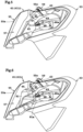
- Fig. 5 illustrates an interior construction of the tank shroud (cover not shown).
- Fig. 6 illustrates the interior construction of the tank shroud.
- Fig. 7 is a sectional view on arrow 100-100 in Fig. 4(b) .
- Fig. 8 is an exploded perspective view of the air guide and the power supply connector.
- Fig. 9 is an enlarged view of the power supply connector in Fig. 7 .
- Fig. 10 is a sectional view on arrow 101-101 in Fig. 9 .
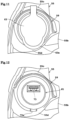
- Fig. 11 is an external view seen from a direction of arrow 102 in Fig. 9 .
- Fig. 12 illustrates the power supply connector in Fig. 11 with a cap not shown.
- the power supply connector 59 includes a body case 61, a cap 63, a cord 65, a male coupler 67, and a latch 69.
- the body case 61 has a cylindrical shape in appearance.
- the body case 61 has a screw portion 71 formed on part of its outer circumferential face.
- the body case 61 has the screw portion 71 formed only on an area close to the cap 63.
- the body case 61 includes a socket 73 inside therein.
- the socket 73 is, for example, one in accordance with a Universal Serial Bus (USB) standard.
- the socket 73 is, for example, a type A of the USB receptacle.
- the type A of the USB receptacle is widely used with high versatility and is suitable.
- the body case 61 has an alignment rib 61a formed on part of its outer circumferential face.
- the alignment rib 61a protrudes radially from the outer circumferential face of the body case 61.
- the alignment rib 61a is formed between the screw portion 71 and the cap 63 of the body case 61.
- a plug of the power supply cord, not shown, is inserted into and pulled out of the socket 73.
- the socket 73 is formed such that the plug of the power supply cord, not shown, is freely inserted thereinto and pulled out thereof.
- the standard of the socket 73 is not limited to the USB.
- the socket 73 may be a cigarette socket or a Hella socket.
- the cigarette socket and the Hella socket are each widely used as a 12V current power supply with high versatility.
- the cap 63 covers rearward and upward of the body case 61.
- the cap 63 covers the socket 73.
- the cap 63 covers the socket 73 in a liquid-tight state. When the cap 63 covers the socket 73, the socket 73 is invisible from outside.
- the cap 63 can be attached to and detached from the body case 61 freely.
- the cap 63 is preferably made of an elastic member, for example.
- the cap 63 is made of rubber, for example. Since the cap 63 is an elastic member, the cap 63 can be attached to and detached from the body case 61 easily.
- the cap 63 is partially fixed to the body case 61. Accordingly, even when the cap 63 is removed and the socket 73 is exposed, the cap 63 is not completely separated from the body case 61. Therefore, the cap 63 is unlikely to be lost after the cap 63 is removed.
- the socket 73 is connected to one end of the cord 65.
- the cord 65 extends from the body case 61.
- the male coupler 67 is connected to the other end of the cord 65.
- the socket 73 and the male coupler 67 are electrically conductive.
- the male coupler 67 is attachable and detachable freely to and from a female coupler 68.
- the female coupler 68 is connected to one end of an electrical source cord 68a.
- the other end of the electrical source cord 68a is electrically connected to a battery, not shown, of the straddled vehicle.
- the female coupler 68 is electrically connected to the electrical source cord 68a extending from the battery not shown. Power in accordance with the USB standard is supplied to the electrical source cord 68a via a voltage converter not shown. Accordingly, power in accordance with the USB standard is supplied to the socket 73.
- the body case 61 is fixed to the air guide 55 with the latch 69.
- the body case 61 is fixed to the ceiling portion 55b by turning the latch 69 into the screw portion 71.
- the ceiling portion 55b has an insertion opening 75 at its attachment projection 55c.
- the insertion opening 75 is a through hole.
- the insertion opening 75 is formed at a rear part and an upper part of the attachment projection 55c.
- the insertion opening 75 has an internal diameter larger than an outer diameter of the body case 61 in a direction where the cord 65 extends.
- the internal diameter of the insertion opening 75 is larger than an outer diameter of the screw portion 71.
- the ceiling portion 55b has a recess 55d rearward of the cap 63.
- the recess 55d is positioned below the flange 63a of the cap 63.
- the recess 55d is positioned lower than the ceiling portion 55b.
- the insertion opening 75 has a notch 75a.
- the notch 75a extends rearward from a rear part of the insertion opening 75.
- the notch 75a is formed at a part of an inner circumference face of the insertion opening 75 in a direction of the recess 55d.
- the notch 75a protrudes in a radial direction of the insertion opening 75.
- the notch 75a has a dimension where the alignment rib 61a of the body case 61 is inserted. In other words, the notch 75a is formed so as to be slightly larger than the alignment rib 61a.
- the rib 61a of the body case 61 is inserted into the notch 75a, leading to prevention of the body case 61 from rotating around a longitudinal axis.
- the notch 75a is longer than the alignment rib 61a in a radial direction of the insertion opening 75.
- the alignment rib 61a is shorter than the notch 75a in a radial length of the insertion opening 75. Consequently, the notch 75a is not closed while the body case 61 is inserted into the insertion opening 75 and the alignment rib 61a is inserted into the notch 75a. That is, the notch 75a has a gap. The gap is present between the notch 75a and the alignment rib 61a. Thereby, rain drops fall down from the gap of the notch 75a. Consequently, rain drops are never stored in the recess 55d. As a result, the power supply connector 59 from which the cap 63 is removed can be suppressed from being under water.
- the power supply connector 59 is attached to the attachment projection 55c in such a configuration as described above.
- the power supply connector 59 includes a body case 61 whose longitudinal axis (long axis) has a predetermined angle ⁇ relative to the vehicle front-back direction X.
- the predetermined angle is approximately 45 degrees, for example.
- the tank shroud 41L includes a cover 81.
- the cover 81 is located forward of the power supply connector 59.
- the cover 81 covers the power supply connector 59 from forward in the vehicle front-back direction X.
- the cover 81 covers the body case 61 and the cord 65 from forward.
- the cover 81 is preferably an elastic member.
- the cover 81 is made of rubber, for example.
- the cover 81 has an opening 81a rearward in the vehicle front-back direction X.
- the cover 81 is opened in a downstream direction of the opening 57.
- the cover 81 has a bowl shape, for example, that bulges forward. Accordingly, heat can be released in the downstream direction of the opening 81a in the cover 81 even when the body case 61, the cord 65, the male coupler 67, or the female coupler 68 is heated by supplying electricity. This results in suppression of heating of the power supply connector 59 and the like.
- the cover 81 covers only upstream of the opening 57. As shown in Fig. 4(a) , the cover 81 only closes the opening 57 partially, seen from forward in the vehicle front-back direction X. The cover 81 does not close the entire of the opening 57. The cover 81 allows air flowing from the opening 57 to exhaust through the air grille 51. Accordingly, heat can be released by air flowing from the opening 57 to the air grille 51 even when the body case 61, the cord 65, the male coupler 67, or the female coupler 68 is heated by supplying electricity. This results in more suppression of heating of the power supply connector 59 and the like.
- the cover 81 covers the body case 61 and the cord 65 from forward. Consequently, the body case 61 and the cord 65 are invisible from the opening 57 of the tank shroud 41L. This results in enhanced aesthetics of the straddled vehicle 1.
- the coupler formed by connection of the male coupler 67 and the female coupler 68 is covered with the cover 81 from forward. Accordingly, the cover 81 makes the male coupler 67 and the female coupler 68 invisible from forward through the opening 57 of the tank shroud 41L. This results in enhanced aesthetics of the straddled vehicle 1.
- the cover 81 is an elastic member.
- the cover 81 is made of rubber, for example.
- the power supply connector 59 provided in such a manner as described above is visible on the upper face of the tank shroud 41L in side view of the vehicle, as shown in Figs. 1 and 4(c) . Accordingly, the power supply connector 59 partially protrudes upward of the tank shroud 41L. Consequently, the driver can easily connect the power supply cord to the power supply connector 59.
- the body case 61 includes the cap 63 for covering the socket 73.
- the cap 63 is moved upward and is opened.
- the ceiling portion 55b includes the recess 55d.
- the recess 55d is located rearward of the cap 63. Consequently, it is easy for the driver to catch the cap 63 with the fingers. Therefore, the driver can move the cap 63 easily.
- the cap 63 includes the flange 63a.
- the flange 63a protrudes rearward from the body case 61.
- the flange 63a is positioned above the recess 55d. Consequently, it is easier for the driver to catch the flange 63a with the fingers. Therefore, the driver can move the cap 63 easily.
- connection of the male coupler 67 to the female coupler 68 makes electrical connection between the electrical source cord, not shown, extending from the battery, and the cord 65.
- the male coupler 67 and the female coupler 68 make easy connection between the power supply connector 59 attached to the tank shroud 41L and the battery.
- the power supply connector 59 is provided on the left tank shroud 41L.
- the left tank shroud 41L is located at a low position while the straddled vehicle 1 stops and is inclined leftward by a side stand.
- the driver is normally on the left side of the straddled vehicle 1, and thus the power supply connector 59 is easily visible to the driver.
- the driver easily applies force when inserting the power supply cord into the power supply connector 59.
- the driver can easily connect the power supply cord to the power supply connector 59.
- the tank shroud 41 corresponds to the "side cover” in the present invention.
- the air scoop 47 and the inner panel 49 correspond to the "outer panel member” in the present invention.
- the air guide 55 and the ceiling portion 55b correspond to the "ceiling member” in the present invention.
- the female coupler 68 corresponds to the "first coupler” in the present invention.
- the male coupler 67 corresponds to the "second coupler” in the present invention.
- the male coupler 67 and the female coupler 68 correspond to the "coupler" in the present invention.
Landscapes
- Engineering & Computer Science (AREA)
- Mechanical Engineering (AREA)
- Automatic Cycles, And Cycles In General (AREA)
Abstract
Description
- The present invention relates to a straddled vehicle that travels while a driver sits astride the vehicle.
- Such a currently-used type of devices includes one having a tank and a tank shroud. See, for example,
JP 2015-83395 A - The tank shroud has a left part provided with an article storage between the inner shroud and the outer shroud. The article storage includes a storage space. The storage space is formed by a bottom wall, a front wall, a rear wall, an outer wall, and an inner wall. The article storage is provided with a power supply connector on the rear wall. The power supply connector is connected to a battery. A power supply cord for an electronic device like a smartphone is connected to the power supply connector by the driver.
- However, the example of the currently-used apparatus with such a construction has the following drawback. That is, the power supply connector is provided on the rear wall of the currently-used apparatus, and thus a socket of the power supply connector is opened forward. Consequently, the power supply connector is invisible to the driver. As a result, it is difficult for the driver to attach the power supply cord to the power supply connector.
- It is the object of the present invention to provide a straddled vehicle in which a power supply cord can be attached to a power supply connector easily.
- According to the present invention said object is solved by a straddled vehicle having the features of
independent claim 1. Preferred embodiments are laid down in the dependent claims. - Accordingly, it is provided a straddled vehicle including a frame provided with a head tube on its front part, a fuel tank configured to store a fuel and attached to a part of the frame more rearward than the head tube, a side cover extending from the fuel tank to the head tube in side view, and a power supply connector provided on the side cover and configured to supply power to an electronic device, wherein a power supply cord is inserted into the power supply connector in a forward and downward direction and is pulled out from the power supply connector in a rearward and upward direction.
- According to the present teaching, the power supply connector is provided on the side cover such that the power supply cord it is inserted into the power supply connector in the forward and downward direction and is pulled out from the power supply connector in the rearward and upward direction. Consequently, the power supply connector is easily visible to the driver even when the driver sits astride the straddled vehicle. As a result, it is easy for the driver to attach the power supply cord to the power supply connector.
- Moreover, it is preferred in the aspect of the present teaching that the side cover has an opening in its front part, that the power supply connector includes a body case and a cord extending from the body case, and that the side cover further includes a cover configured to cover the body case and the cord from forward.
- The cover covers the body case and the cord from forward. Consequently, the body case and the cord are invisible from the opening of the side cover. This results in enhanced aesthetics of the straddled vehicle.
- Moreover, it is preferred in the aspect of the present teaching that the cover is an elastic member.
- Since the cover is an elastic member, the body case and the cord can be accessed without removing the cover during maintenance. Thus, the maintainability of the straddled vehicle can be improved.
- Moreover, it is preferred in the aspect of the present teaching that the cover is opened in a downstream direction of the opening.
- Heat can be released in the downstream direction of the opening in the cover even when the body case or the cord is heated by supplying electricity. This results in suppression of heating of the power supply connector.
- Moreover, it is preferred that the side cover includes an outer panel member arranged more outward than the fuel tank and a ceiling member extending from the fuel tank to an upper inner wall of the outer panel member, and that the power supply connector is attached to the ceiling member.
- Among the outer panel member and the ceiling member constituting the side cover, the power supply connector is attached to the ceiling member. Consequently, the power supply connector is easily visible to the driver while the driver sits astride the straddled vehicle. Moreover, the driver can easily access the ceiling member of the side cover. Consequently, it is easy for the driver to connect the power supply cord to the power supply connector.
- Moreover, it is preferred in the aspect of the present teaching that the body case has a cylindrical shape and includes an alignment rib on a part of its outer circumferential face, that the ceiling member has an insertion opening for inserting the body case and a notch for housing the alignment rib and aligning the body case around an axis, and that the notch is longer than the alignment rib in a diametrical direction of the body case.
- The notch is longer than the alignment rib in the diametrical direction of the body case. Consequently, the notch has a gap although the body case is inserted into the insertion opening and the alignment rib is aligned in the notch. As a result, it is possible to prevent accumulation of raindrops on the ceiling member, so that the power supply connector can be suppressed from being under water.
- Moreover, it is preferred in the aspect of the present teaching that the body case includes a detachable cap for covering a socket connected to the cord, that the cap is moved upward from an upper face of the ceiling member and is opened, and that the ceiling member includes a recess rearward of the cap.
- The body case includes the cap for covering the socket. The cap is moved upward and is opened. When opening the cap, the driver can easily move the cap since the recess is formed in the ceiling member.
- Moreover, it is preferred in the aspect of the present teaching that the straddled vehicle includes a coupler having a first coupler connected to an electrical source cord extending from a battery and a second coupler detachably connected to the cord.
- Connection of the first coupler to the second coupler makes electrical connection between the electrical source cord and the cord. The couplers can make easy connection between the power supply connector attached to the side cover and the battery.
- Moreover, it is preferred in the aspect of the present teaching that the coupler having the first coupler and the second coupler whose one end connected to each other is covered with the cover from forward.
- The cover makes the coupler invisible from forward. This achieves enhanced aesthetics.
- Moreover, it is preferred in the aspect of the present teaching that a right part and a left part of the side cover are arranged on a right side and a left side of the fuel tank, respectively, and that the power supply connector is provided on the left part of the side cover selected from the left part and the right part of the side cover.
- The power supply connector is provided on the left part of the side cover. The driver is normally on the left side of the straddled vehicle when the straddled vehicle stops and is inclined leftward by a side stand. Accordingly, the power supply connector is easily visible to the driver. Moreover, the driver easily applies force when inserting the power supply cord into the power supply connector. This results in easy connection of the power supply cord to the power supply connector by the driver.
- Moreover, it is preferred in the aspect of the present teaching that the power supply connector is visible on an upper face of the side cover in side view.
- Since the power supply connector protrudes upward from the side cover, the driver can easily see an operation object. Consequently, the driver can easily connect the power supply cord to the power supply connector.
- Moreover, it is preferred in the aspect of the present teaching that the power supply connector is visible on an upper face of the side cover in front view.
- Since the power supply connector protrudes upward from the side cover, the driver can easily see an operation object. Consequently, the driver can easily connect the power supply cord to the power supply connector.
- In the straddled vehicle according to the present teaching, the power supply connector is provided on the side cover such that the power supply cord is inserted into the power supply connector in the forward and downward direction and is pulled out from the power supply connector in the rearward and upward direction. Consequently, the power supply connector is easily visible to the driver even when the driver sits astride the straddled vehicle. As a result, it is easy for the driver to attach the power supply cord to the power supply connector.
-
-
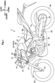
Fig. 1 is a left side view of a straddled vehicle according to an embodiment. -
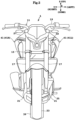
Fig. 2 is a front view of the straddled vehicle according to the embodiment. -
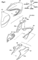
Fig. 3 is an exploded perspective view of a tank shroud. -
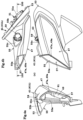
Fig. 4 (a) is a front view,Fig. 4(b) is a plan view, andFig. 4(c) is a left side view of the tank shroud. -
Fig. 5 illustrates an interior construction of the tank shroud (cover not shown). -
Fig. 6 illustrates the interior construction of the tank shroud. -
Fig. 7 is a sectional view on arrow 100-100 inFig. 4(b) . -
Fig. 8 is an exploded perspective view of an air guide and a power supply connector. -
Fig. 9 is a partially enlarged view of the power supply connector inFig. 7 . -
Fig. 10 is a sectional view on arrow 101-101 inFig. 9 . -
Fig. 11 is an external view seen from a 102 direction inFig. 9 . -
Fig. 12 illustrates the power supply connector inFig. 11 with a cap not shown. - The following describes one preferred embodiment with reference to drawings.
- A straddled
vehicle 1 is a street type vehicle. A driver (also called rider) rides on the straddledvehicle 1, and operates the straddledvehicle 1. -
Fig. 1 is a left side view of the straddled vehicle according to an embodiment.Fig. 2 is a front view of the straddled vehicle according to the embodiment. -
Fig. 1 shows a vehicle front-back direction X, a vehicle transverse direction Y, and a vehicle up-down direction Z of the straddledvehicle 1. The vehicle front-back direction X, vehicle transverse direction Y, and vehicle up-down direction Z are defined with reference to a driver riding on the straddledvehicle 1. The vehicle front-back direction X, vehicle transverse direction Y, and vehicle up-down direction Z are perpendicular to one another. The vehicle front-back direction X and vehicle transverse direction Y are horizontal. The vehicle up-down direction Z is vertical. - The terms "forward", "rearward", "upward", "downward", "rightward", and "leftward", respectively, mean "forward", "rearward", "upward", "downward", "rightward", and "leftward" as seen from the driver riding on the straddled
vehicle 1. Unless otherwise stated in this specification, "forward" and "rearward" include not only directions parallel to the vehicle front-back direction X but also directions close to the vehicle front-back direction X. The directions close to the vehicle front-back direction X are, for example, directions at angles not exceeding 45 degrees to the vehicle front-back direction X. Similarly, unless otherwise indicated, "rightward" and "leftward" include not only directions parallel to the vehicle transverse direction Y but also directions close to the vehicle transverse direction Y. Unless otherwise specified, "upward" and "downward" include not only directions parallel to the vehicle up-down direction Z but also directions close to the vehicle up-down direction Z. For reference, the drawings show front, rear, up, down, right, and left, as appropriate. - It is to be understood that, in this specification, various expressions describing arrangements have the following meanings respectively. The following description will be made taking the vehicle transverse direction Y for example, and the same may apply to the vehicle front-back direction X and vehicle up-down direction Z.
- The expression "Member Ma is located more rightward/leftward than Member Mb," defines a position in the vehicle transverse direction Y of Member Ma relative to Member Mb, and does not define a position in the vehicle front-back direction X or the vehicle up-down direction Z of Member Ma relative to Member Mb. In the case of this expression, Member Ma may, or may not overlap Member Mb in a side view of the straddled
vehicle 1. - The expression "Member Ma is located rightward/leftward of Member Mb," without reference to a looking direction defines a position in the vehicle transverse direction Y of Member Ma relative to Member Mb, a position in the vehicle front-back direction X of Member Ma relative to Member Mb, and a position in the vehicle up-down direction Z of Member Ma relative to Member Mb. This expression means that Member Ma is located more rightward/leftward than Member Mb, and that at least part of Member Ma overlaps at least part of Member Mb in a side view of the straddled
vehicle 1. - The expression "Member Ma is located rightward/leftward of Member Mb in plan view of the straddled
vehicle 1," defines a position in the vehicle transverse direction Y of Member Ma relative to Member Mb, and a position in the vehicle front-back direction X of Member Ma relative to Member Mb, and does not define a position in the vehicle up-down direction Z of Member Ma relative to Member Mb. This expression means that Member Ma is located more rightward/leftward than Member Mb, that a front end of Member Ma is positioned more forward than a rear end of Member Mb, and that a rear end of Member Ma is located more rearward than a front end of Member Mb. - The expression "Member Ma is located rightward/leftward of Member Mb in front view of the straddled
vehicle 1," defines a position in the vehicle transverse direction Y of Member Ma relative to Member Mb, and a position in the vehicle up-down direction Z of Member Ma relative to Member Mb, and does not define a position in the vehicle front-back direction X of Member Ma relative to Member Mb. This expression means that Member Ma is located more rightward/leftward than Member Mb, that an upper end of Member Ma is positioned higher than a lower end of Member Mb, and that a lower end of Member Ma is located lower than an upper end of Member Mb. - In the present specification, the language "in side view of the straddled
vehicle 1" is referred to as "in side view of the vehicle", as appropriate. Likewise, the language "in plan view of the straddledvehicle 1" is referred to as "in plan view of the vehicle", as appropriate. The language "in front view of the straddledvehicle 1" is referred to as "in front view of the vehicle", as appropriate. - The straddled
vehicle 1 includes abody frame 3. Thevehicle body frame 3 includes a head tube 5 and amain frame 7. Thebody frame 3 includes the head tube 5 at its front part. The head tube 5 is located at a front part of the straddledvehicle 1. Themain frame 7 extends rearward and downward from the head tube 5 in side view of the vehicle. - The straddled
vehicle 1 includes asteering device 11. Thesteering device 11 is supported by thebody frame 3. Specifically, thesteering device 11 is supported by the head tube 5. Thesteering device 11 is rotatable relative to thebody frame 3. - The
steering device 11 includes atop bridge 13, abottom bridge 15, and afront suspension 17. Thetop bridge 13 is located higher than the head tube 5. Thebottom bridge 15 is located lower than thetop bridge 13. Thebottom bridge 15 is located lower than the head tube 5. Thefront suspension 17 is supported by thetop bridge 13 and thebottom bridge 15. Thefront suspension 17 extends forward and downward from thetop bridge 13 in side view of the vehicle. Thefront suspension 17 extends to a position lower than thebottom bridge 13. - The
steering device 11 includes ahandlebar 19. Thehandlebar 19 is supported by thetop bridge 13. Thehandlebar 19 is entirely located higher than thetop bridge 13, for example. The driver grips thehandlebar 19 and steers thesteering device 11. - The
steering device 11 includes afront axle 21. Thefront axle 21 is located lower than thebottom bridge 15. Thefront axle 21 is supported by thefront suspension 17. Thefront axle 21 is provided on a lower end of thefront suspension 17. - The straddled
vehicle 1 includes afront wheel 23. Thefront wheel 23 is supported by thesteering device 11. Specifically, thefront wheel 23 is supported by thefront axle 21. Thefront wheel 23 is rotatable about thefront axle 21. - The straddled
vehicle 1 includes anengine 25. Theengine 25 is supported by thebody frame 3. Specifically, theengine 25 is supported by themain frame 7. Theengine 25 is fixed to thebody frame 3. Theengine 25 does not swing relative to thevehicle body frame 3. Theengine 25 generates a driving force for traveling the straddledvehicle 1. - At least part of the
engine 25 is located below themain frame 7 in side view of the vehicle. Theengine 25 is located rearward of thesteering device 11 in side view of the vehicle. - The straddled
vehicle 1 includes afuel tank 27. Thefuel tank 27 is supported by thebody frame 3. Specifically, thefuel tank 27 is supported by themain frame 7. Thefuel tank 27 stores a fuel to be supplied to theengine 25. - At least part of the
fuel tank 27 is located above themain frame 7 in side view of the vehicle. Thefuel tank 27 is located rearward of thesteering device 11 in side view of the vehicle. Thefuel tank 27 is located above theengine 25 in side view of the vehicle. - The straddled
vehicle 1 includes aseat 29. Theseat 29 is supported by thebody frame 3. Specifically, theseat 29 is supported by aseat frame 31 of thebody frame 3. Theseat frame 31 extends rearward of thebody frame 3. Theseat frame 31 is inclined rearward and upward in side view of the vehicle. Theseat frame 31 is attached to themain frame 7. - The
seat 29 is located more rearward and higher than theengine 25. Theseat 29 is located rearward of thefuel tank 27 in side view of the vehicle. At least part of theseat 29 is located at a position equal in level to thefuel tank 27. - The straddled
vehicle 1 includes apivot shaft 33, aswing arm 35, arear axle 37, and arear wheel 39. - The
pivot shaft 33 is supported by thebody frame 3. Specifically, thepivot shaft 33 is supported by themain frame 7. Theswing arm 35 is supported by thepivot shaft 33. Theswing arm 35 is swingable about thepivot shaft 33 relative to thebody frame 3. Theswing arm 35 extends rearward from thepivot shaft 33 in side view of the vehicle. Therear axle 37 is supported by a rear part of theswing arm 35. Therear wheel 39 is supported by therear axle 37. Therear wheel 39 is rotatable about therear axle 37. Theswing arm 35 and therear wheel 39 are located rearward of theengine 25 in side view of the vehicle. Theswing arm 35 and therear wheel 39 are located lower than thefuel tank 27 and theseat 29. - The
fuel tank 27 includes atank shroud 41 on its left side and its right side in the vehicle transverse direction Y in plan view of the vehicle. If thetank shroud 41 on the right and left sides is distinguished for explanation, aleft tank shroud 41 is referred to as atank shroud 41L and aright tank shroud 41 is referred to as atank shroud 41R. - The
tank shroud 41 partially overlaps thefuel tank 27 in side view of the vehicle. Thetank shroud 41 extends from thefuel tank 27 to the head tube 5. Thetank shroud 41 partially covers the head tube 5 in side view of the vehicle. Thetank shroud 41 is long in the vehicle front-back direction X. Thetank shroud 41 is a side board or a partition provided on thefuel tank 27. Thetank shroud 41 is sometimes called a shroud simply. Thetank shroud 41 is sometimes called a tank cover. Thetank shroud 41 is sometimes called a lateral wall board or a partition member. - Now, reference is made to
Figs. 3 and4 .Fig. 3 is an exploded perspective view of the tank shroud.Fig. 4(a) is a front view,Fig. 4(b) is a plan view, andFig. 4(c) is a left side view of the tank shroud. - Hereunder, explanation is only made of the
left tank shroud 41L of the left andright tank shrouds right tank shroud 41R differs from theleft tank shroud 41L in construction of anair guide 55. - A
fuel tank cover 43 is attached to thefuel tank 27. Thefuel tank cover 43 is attached so as to cover an outer circumferential face of thefuel tank 27. Thefuel tank cover 43 has anattachment notch 45. Theattachment notch 45 is formed by cutting out an area of the fuel tank cover 43 corresponding to front right and left sides of thefuel tank 27. Theattachment notch 45 is formed by cutting out an area of thefuel tank cover 43, the area being in a front direction X and the vehicle transverse direction Y of thefuel tank 27. Thetank shroud 41L is attached to theattachment notch 45 and then is attached to thefuel tank 27 together with thefuel tank cover 43. - The
tank shroud 41L includes anair scoop 47, aninner panel 49, anair grille 51, aduct 53, and anair guide 55. Theair scoop 47 is also called an outer shroud. Theair guide 55 is also called an inner shroud. - The
air scoop 47 constitutes an outermost member in the vehicle transverse direction Y. Theair scoop 47 constitutes an outer panel of thetank shroud 41L. Theair scoop 47 is a thin plate member in the vehicle up-down direction Z and the vehicle front-back direction X. Theair scoop 47 has arecess 47a formed therein. Therecess 47a protrudes leftward in the vehicle transverse direction Y. Theair scoop 47 is formed by a plate member curved along a plane in the vehicle front-back direction X and the vehicle up-down direction Z. - The
inner panel 49 is attached on the right side of theair scoop 47 in the vehicle transverse direction Y. Theinner panel 49 is attached to therecess 47a of theair scoop 47. Theinner panel 49 has arecess 49a formed therein with the same shape as that of therecess 47a in theair scoop 47. Therecess 49a protrudes leftward in the vehicle transverse direction Y. Theinner panel 49 is formed by a plate member curved along a plane in the vehicle front-back direction X and vehicle up-down direction Z. - The
air grille 51 is attached to theduct 53. Theair grille 51 is attached inside of theduct 53. Theair grille 51 has aslit outlet 51a formed therein rearward in the vehicle front-back direction X. Theair grille 51 guides air, caught into from a front part, rearward of theoutlet 51a. - The
air guide 55 constitutes an innermost part of thetank shroud 41L in the vehicle transverse direction Y. Theair guide 55 is located closest to thefuel tank 27 in the vehicle transverse direction Y. Theair guide 55 is a thin-plate member along a plane in the vehicle up-down direction Z and the vehicle front-back direction X. Theair guide 55 has arecess 55a formed therein. Therecess 55a protrudes rightward in the vehicle transverse direction Y. Theair guide 55 is formed by a thin-plate member. Theair guide 55 has aceiling portion 55b formed at an upper part thereof in the vehicle up-down direction Z. Theceiling portion 55b extends from thefuel tank 27 to upper inner walls of theair scoop 47 and theinner panel 49. - The
ceiling portion 55b of theair guide 55 has anattachment projection 55c formed therein. Theattachment projection 55c protrudes from theceiling portion 55b upward in the vehicle up-down direction Z. - The
air guide 55 is attached to theduct 53, and then is attached to theattachment notch 45 of the fuel tank cover 43 together with theair scoop 47, theinner panel 49, and theair grille 51. Thefuel tank cover 43 is attached to thefuel tank 27. Thereby, thetank shroud 41L is attached to thefuel tank 27. Thetank shroud 41L is assembled in such a manner as described above, whereby anopening 57 is formed forward in the vehicle front-back direction X with therecess 49a and therecess 55a. - A
power supply connector 59 is attached to theattachment projection 55c. Thepower supply connector 59 supplies power to an electronic device. Examples of the electronic device include a portable phone, a smart phone, an imaging device for capturing a still image and a moving image, and a radar detector. - Reference is now made to
Figs. 5 to 12 .Fig. 5 illustrates an interior construction of the tank shroud (cover not shown).Fig. 6 illustrates the interior construction of the tank shroud.Fig. 7 is a sectional view on arrow 100-100 inFig. 4(b) .Fig. 8 is an exploded perspective view of the air guide and the power supply connector.Fig. 9 is an enlarged view of the power supply connector inFig. 7 .Fig. 10 is a sectional view on arrow 101-101 inFig. 9 .Fig. 11 is an external view seen from a direction ofarrow 102 inFig. 9 .Fig. 12 illustrates the power supply connector inFig. 11 with a cap not shown. - The
power supply connector 59 includes abody case 61, acap 63, acord 65, amale coupler 67, and alatch 69. - The
body case 61 has a cylindrical shape in appearance. Thebody case 61 has ascrew portion 71 formed on part of its outer circumferential face. Thebody case 61 has thescrew portion 71 formed only on an area close to thecap 63. Thebody case 61 includes asocket 73 inside therein. - The
socket 73 is, for example, one in accordance with a Universal Serial Bus (USB) standard. Thesocket 73 is, for example, a type A of the USB receptacle. The type A of the USB receptacle is widely used with high versatility and is suitable. Thebody case 61 has analignment rib 61a formed on part of its outer circumferential face. Thealignment rib 61a protrudes radially from the outer circumferential face of thebody case 61. Thealignment rib 61a is formed between thescrew portion 71 and thecap 63 of thebody case 61. A plug of the power supply cord, not shown, is inserted into and pulled out of thesocket 73. Thesocket 73 is formed such that the plug of the power supply cord, not shown, is freely inserted thereinto and pulled out thereof. - The standard of the
socket 73 is not limited to the USB. For example, thesocket 73 may be a cigarette socket or a Hella socket. The cigarette socket and the Hella socket are each widely used as a 12V current power supply with high versatility. - The
cap 63 covers rearward and upward of thebody case 61. Thecap 63 covers thesocket 73. Thecap 63 covers thesocket 73 in a liquid-tight state. When thecap 63 covers thesocket 73, thesocket 73 is invisible from outside. Thecap 63 can be attached to and detached from thebody case 61 freely. Thecap 63 is preferably made of an elastic member, for example. Thecap 63 is made of rubber, for example. Since thecap 63 is an elastic member, thecap 63 can be attached to and detached from thebody case 61 easily. Thecap 63 is partially fixed to thebody case 61. Accordingly, even when thecap 63 is removed and thesocket 73 is exposed, thecap 63 is not completely separated from thebody case 61. Therefore, thecap 63 is unlikely to be lost after thecap 63 is removed. - The
cap 63 has aflange 63a formed so as to protrude from a part of thecap 63 outward in a plane direction of thecap 63. Theflange 63a protrudes rearward from thebody case 61. Thealignment rib 61a described above is covered with theflange 63a in 102-arrow direction, as shown inFig. 9 . The driver can attach and detach thecap 63 by catching theflange 63a with the fingers. Thecap 63 can be attached to and detached from thebody case 61 easily with theflange 63a. - The
socket 73 is connected to one end of thecord 65. Thecord 65 extends from thebody case 61. Themale coupler 67 is connected to the other end of thecord 65. Thesocket 73 and themale coupler 67 are electrically conductive. As shown inFigs. 5 and 6 , themale coupler 67 is attachable and detachable freely to and from afemale coupler 68. Thefemale coupler 68 is connected to one end of anelectrical source cord 68a. The other end of theelectrical source cord 68a is electrically connected to a battery, not shown, of the straddled vehicle. Thefemale coupler 68 is electrically connected to theelectrical source cord 68a extending from the battery not shown. Power in accordance with the USB standard is supplied to theelectrical source cord 68a via a voltage converter not shown. Accordingly, power in accordance with the USB standard is supplied to thesocket 73. - As shown in
Figs. 8 and9 , thebody case 61 is fixed to theair guide 55 with thelatch 69. Thebody case 61 is fixed to theceiling portion 55b by turning thelatch 69 into thescrew portion 71. - As shown in
Fig. 8 , theceiling portion 55b has aninsertion opening 75 at itsattachment projection 55c. Theinsertion opening 75 is a through hole. Theinsertion opening 75 is formed at a rear part and an upper part of theattachment projection 55c. Theinsertion opening 75 has an internal diameter larger than an outer diameter of thebody case 61 in a direction where thecord 65 extends. The internal diameter of theinsertion opening 75 is larger than an outer diameter of thescrew portion 71. As shown inFig. 9 , theceiling portion 55b has arecess 55d rearward of thecap 63. Therecess 55d is positioned below theflange 63a of thecap 63. Therecess 55d is positioned lower than theceiling portion 55b. - As shown in
Figs. 9, 10 , and12 , theinsertion opening 75 has anotch 75a. Thenotch 75a extends rearward from a rear part of theinsertion opening 75. Thenotch 75a is formed at a part of an inner circumference face of theinsertion opening 75 in a direction of therecess 55d. Thenotch 75a protrudes in a radial direction of theinsertion opening 75. Thenotch 75a has a dimension where thealignment rib 61a of thebody case 61 is inserted. In other words, thenotch 75a is formed so as to be slightly larger than thealignment rib 61a. Therib 61a of thebody case 61 is inserted into thenotch 75a, leading to prevention of thebody case 61 from rotating around a longitudinal axis. - The
notch 75a is longer than thealignment rib 61a in a radial direction of theinsertion opening 75. In other words, thealignment rib 61a is shorter than thenotch 75a in a radial length of theinsertion opening 75. Consequently, thenotch 75a is not closed while thebody case 61 is inserted into theinsertion opening 75 and thealignment rib 61a is inserted into thenotch 75a. That is, thenotch 75a has a gap. The gap is present between thenotch 75a and thealignment rib 61a. Thereby, rain drops fall down from the gap of thenotch 75a. Consequently, rain drops are never stored in therecess 55d. As a result, thepower supply connector 59 from which thecap 63 is removed can be suppressed from being under water. - The
power supply connector 59 is attached to theattachment projection 55c in such a configuration as described above. Thepower supply connector 59 includes abody case 61 whose longitudinal axis (long axis) has a predetermined angle θ relative to the vehicle front-back direction X. The predetermined angle is approximately 45 degrees, for example. Thereby, the plug for the power supply cord not shown is inserted into thepower supply connector 59 in the forward and downward direction. The plug of the power supply cord not shown is pulled out from thepower supply connector 59 in the rearward and upward direction. That is, the power supply cord not shown is inserted into thepower supply connector 59 in the forward and downward direction and is pulled out from thepower supply connector 59 in the rearward and upward direction. - As shown in
Figs. 6 and7 , thetank shroud 41L includes acover 81. Thecover 81 is located forward of thepower supply connector 59. Thecover 81 covers thepower supply connector 59 from forward in the vehicle front-back direction X. - Specifically, the
cover 81 covers thebody case 61 and thecord 65 from forward. Thecover 81 is preferably an elastic member. Thecover 81 is made of rubber, for example. Thecover 81 has anopening 81a rearward in the vehicle front-back direction X. Thecover 81 is opened in a downstream direction of theopening 57. Thecover 81 has a bowl shape, for example, that bulges forward. Accordingly, heat can be released in the downstream direction of theopening 81a in thecover 81 even when thebody case 61, thecord 65, themale coupler 67, or thefemale coupler 68 is heated by supplying electricity. This results in suppression of heating of thepower supply connector 59 and the like. - Moreover, the
cover 81 covers only upstream of theopening 57. As shown inFig. 4(a) , thecover 81 only closes theopening 57 partially, seen from forward in the vehicle front-back direction X. Thecover 81 does not close the entire of theopening 57. Thecover 81 allows air flowing from theopening 57 to exhaust through theair grille 51. Accordingly, heat can be released by air flowing from theopening 57 to theair grille 51 even when thebody case 61, thecord 65, themale coupler 67, or thefemale coupler 68 is heated by supplying electricity. This results in more suppression of heating of thepower supply connector 59 and the like. - The
cover 81 covers thebody case 61 and thecord 65 from forward. Consequently, thebody case 61 and thecord 65 are invisible from theopening 57 of thetank shroud 41L. This results in enhanced aesthetics of the straddledvehicle 1. - The coupler formed by connection of the
male coupler 67 and thefemale coupler 68 is covered with thecover 81 from forward. Accordingly, thecover 81 makes themale coupler 67 and thefemale coupler 68 invisible from forward through theopening 57 of thetank shroud 41L. This results in enhanced aesthetics of the straddledvehicle 1. - Moreover, the
cover 81 is an elastic member. Thecover 81 is made of rubber, for example. As a result, thebody case 61 and thecord 65 can be accessed simply by turning thecover 81 without removing thecover 81 during maintenance. Thus, the maintainability can be improved. - The
power supply connector 59 provided in such a manner as described above is visible on the upper face of thetank shroud 41L in side view of the vehicle, as shown inFigs. 1 and4(c) . Accordingly, thepower supply connector 59 partially protrudes upward of thetank shroud 41L. Consequently, the driver can easily connect the power supply cord to thepower supply connector 59. - The
power supply connector 59 is visible on the upper face of thetank shroud 41L in front view of the vehicle, as shown inFigs. 2 and4(a) . Accordingly, thepower supply connector 59 partially protrudes upward of thetank shroud 41L. Consequently, the driver can easily connect the power supply cord to thepower supply connector 59. - According to this embodiment, the
power supply connector 59 is provided on thetank shroud 41L such that the power supply cord is inserted into thepower supply connector 59 in the forward and downward direction and is pulled out from thepower supply connector 59 in the rearward and upward direction. Consequently, thepower supply connector 59 is easily visible to the driver even when the driver sits astride the straddledvehicle 1. As a result, it is easy for the driver to attach the power supply cord to thepower supply connector 59. - Moreover, among members constituting the
tank shroud 41L, thepower supply connector 59 is attached to theceiling portion 55b of theair guide 55. Consequently, thepower supply connector 59 is easily visible to the driver while the driver sits astride the straddledvehicle 1. Moreover, the driver can easily access theceiling portion 55b of thetank shroud 41L. Consequently, it is easy for the driver to connect the power supply cord to thepower supply connector 59. - The
body case 61 includes thecap 63 for covering thesocket 73. Thecap 63 is moved upward and is opened. Theceiling portion 55b includes therecess 55d. Therecess 55d is located rearward of thecap 63. Consequently, it is easy for the driver to catch thecap 63 with the fingers. Therefore, the driver can move thecap 63 easily. - Moreover, the
cap 63 includes theflange 63a. Theflange 63a protrudes rearward from thebody case 61. Theflange 63a is positioned above therecess 55d. Consequently, it is easier for the driver to catch theflange 63a with the fingers. Therefore, the driver can move thecap 63 easily. - Connection of the
male coupler 67 to thefemale coupler 68 makes electrical connection between the electrical source cord, not shown, extending from the battery, and thecord 65. Themale coupler 67 and thefemale coupler 68 make easy connection between thepower supply connector 59 attached to thetank shroud 41L and the battery. - The
power supply connector 59 is provided on theleft tank shroud 41L. Theleft tank shroud 41L is located at a low position while the straddledvehicle 1 stops and is inclined leftward by a side stand. The driver is normally on the left side of the straddledvehicle 1, and thus thepower supply connector 59 is easily visible to the driver. Moreover, the driver easily applies force when inserting the power supply cord into thepower supply connector 59. As a result, the driver can easily connect the power supply cord to thepower supply connector 59. - Here, a correspondence of the construction between the above embodiment and the present invention is as under.
- The tank shroud 41 (41L) corresponds to the "side cover" in the present invention. The
air scoop 47 and theinner panel 49 correspond to the "outer panel member" in the present invention. Theair guide 55 and theceiling portion 55b correspond to the "ceiling member" in the present invention. Thefemale coupler 68 corresponds to the "first coupler" in the present invention. Themale coupler 67 corresponds to the "second coupler" in the present invention. Themale coupler 67 and thefemale coupler 68 correspond to the "coupler" in the present invention. - (1) In the embodiment described above, the
power supply connector 59 is provided on theleft tank shroud 41L. Alternatively, thepower supply connector 59 may be provided on theright tank shroud 41R. Moreover, apower supply connector 59 may be provided on each of thetank shrouds - (2) In the embodiment described above, the
cover 81 with theopening 81a is provided. Alternatively, such a configuration is adoptable that thecover 81 also closes a downstream side. - (3) In the embodiment described above, the
power supply connector 59 is provided on theceiling portion 55b of theair guide 55. Alternatively, thepower supply connector 59 may be provided on another part of theair guide 55 or another member such as theduct 53. Moreover, thepower supply connector 59 is attached to theattachment projection 55c of theair guide 55. Alternatively, thepower supply connector 59 may be directly attached to theceiling portion 55b of theair guide 55. - (4) In the embodiment described above, the
power supply connector 59 is attached such that thepower supply connector 59 includes thebody case 61 whose longitudinal axis has an upward angle θ of approximately 45 degrees relative to the vehicle front-back direction X. However, thepower supply connector 59 only needs to be provided on thetank shroud 41 in such a manner that the plug for the power supply cord not shown is inserted into thepower supply connector 59 in the forward and downward direction and is pulled out from thepower supply connector 59 in the rearward and upward direction. - (5) In the embodiment described above, the
body case 61 includes thealignment rib 61a. However, it is not always necessary that thebody case 61 includes thealignment rib 61a. - (6) In the embodiment described above, the
notch 75a is longer than thealignment rib 61a. - (7) In the embodiment described above, the
air guide 55 includes therecess 55d in theceiling portion 55b. - (8) In the embodiment described above, the
cord 65 is attachable and detachable freely to and from the battery with themale coupler 67 and thefemale coupler 68. Alternatively, thecord 65 may be directly connected to the battery. - (9) In the embodiment described above, the
power supply connector 59 is visible in front view and side view of the vehicle. Alternatively, thepower supply connector 59 may be invisible in front view of the vehicle. Thepower supply connector 59 may be invisible in side view of the vehicle. Thepower supply connector 59 may be invisible both in front view and side view of the vehicle. Alternatively, thepower supply connector 59 may be visible in either front view or side view of the vehicle. - (10) In the embodiment described above, the
tank shroud 41 extends from thefuel tank 27 to the head tube 5 to cover the head tube 5 partially. Alternatively, thetank shroud 41 may only overlap thefuel tank 27 in side view of the vehicle and not cover the head tube 5 partially. Moreover, thetank shroud 41 may extend from thefuel tank 27 to a front side of the head tube 5 to cover an upper part of the front suspension. Thetank shroud 41 may be arranged rightward and leftward of a radiator (with no numeral) configured to cool theengine 25. Thetank shroud 41 may cover at least part of the radiator (with no numeral). Moreover, thetank shroud 41 may extend to the head tube 5 and be connected to a rear side of a cowl including a headlight. -
- 1
- straddled vehicle
- 3
- body frame
- 5
- head tube
- 25
- engine
- 41, 41L, 41R
- tank shroud
- 43
- fuel tank cover
- 45
- attachment notch
- 47
- air scoop
- 47a
- recess
- 49
- inner panel
- 49a
- recess
- 51
- air grille
- 51a
- outlet
- 53
- duct
- 55
- air guide
- 55a
- recess
- 55b
- ceiling portion
- 55c
- attachment projection
- 55d
- recess
- 57
- opening
- 59
- power supply connector
- 61
- body case
- 61a
- alignment rib
- 63
- cap
- 65
- cord
- 67
- male coupler
- 68
- female coupler
- 73
- socket
- 75
- insertion opening
- 75a
- notch
- 81
- cover
Claims (13)
- A straddled vehicle (1), comprising:a frame (3) provided with a head tube (5) on its front part with regard to a vehicle front-back direction (X);a fuel tank (27) configured to store a fuel and attached to a part of the frame (3) more rearward than the head tube (5) with regard to the vehicle front-back direction (X);a side cover (41) overlapping the fuel tank (27) in side view of the vehicle; anda power supply connector (59) provided on the side cover (41) and configured to supply power to an electronic device, whereinthe power supply connector (59) is configured such that a power supply cord can be inserted into the power supply connector (59) in a forward and downward direction and pulled out from the power supply connector (59) in a rearward and upward direction with regard to the vehicle front-back direction (X) and a vehicle up-down direction (Z).
- The straddled vehicle (1) according to claim 1, wherein the side cover (41) has an opening (57) in its front part with regard to the vehicle front-back direction (X),the power supply connector (59) includes a body case (61), and a cord (65) extending from the body case (61), andthe side cover (41) further includes a cover (81) configured to cover at least the body case (61) and the cord (65) from forward with regard to the vehicle front-back direction (X).
- The straddled vehicle (1) according to claim 2, wherein the cover (81) is an elastic member.
- The straddled vehicle (1) according to claim 2, wherein the cover (81) is opened in a downstream direction of the opening (57).
- The straddled vehicle (1) according to any of claims 2 to 4, wherein, the side cover (41) includes an outer panel member (47, 49) arranged more outward than the fuel tank (27) and a ceiling member (55, 55b) extending from the fuel tank (27) to an upper inner wall of the outer panel member (47, 49), and
the power supply connector (59) is attached to the ceiling member (55, 55b). - The straddled vehicle (1) according to claim 5, wherein the body case (61) has a cylindrical shape and includes an alignment rib (61a) on a part of its outer circumferential face,the ceiling member (55, 55b) has an insertion opening (75) for inserting the body case (61) and a notch (75a) for housing the alignment rib (61a) and aligning the body case (61) around an axis, andthe notch (75a) is longer than the alignment rib (61a) in a diametrical direction of the body case (61).
- The straddled vehicle (1) according to claim 6, wherein the body case (61) includes a detachable cap (63) for covering a socket (73) connected to the cord (65),the cap (63) is configured to be movable upward with regard to the vehicle up-down direction (Z) from an upper face of the ceiling member (55, 55b) and to open the power supply connector (59), andthe ceiling member (55, 55b) includes a recess rearward of the cap (63) with regard to the vehicle front-back direction (X).
- The straddled vehicle (1) according to any of claims 2 to 7, further comprising:
a coupler having a first coupler (68) connected to an electrical source cord (68a) extending from a battery and a second coupler (67) detachably connected to the cord (65). - The straddled vehicle (1) according to claim 8, wherein the coupler having the first coupler (68) and the second coupler (67) connected to each other is covered with the cover (81) from forward with regard to the vehicle front-back direction (X).
- The straddled vehicle (1) according to any of claims 2 to 7, wherein the body case (61) with a longitudinal axis thereof having a predetermined angle (θ) relative to the vehicle front-back direction (X) of approximately 45 degrees.
- The straddled vehicle (1) according to any of claims 1 to 10, wherein a right part and a left part of the side cover (41) are arranged on a right side and a left side of the fuel tank (27), respectively, and
the power supply connector (59) is provided on the left part of the side cover (41L) selected from the left part and the right part of the side cover (41L, 41R). - The straddled vehicle (1) according to any of claims 1 to 11, wherein the power supply connector (59) is visible on an upper face of the side cover (41) in side view of the vehicle.
- The straddled vehicle (1) according to claim 1 to 12, wherein the power supply connector (59) is visible on an upper face of the side cover (41) in front view of the vehicle.
Applications Claiming Priority (1)
| Application Number | Priority Date | Filing Date | Title |
|---|---|---|---|
| JP2023171356A JP2025062351A (en) | 2023-10-02 | 2023-10-02 | Saddle-type vehicle |
Publications (2)
| Publication Number | Publication Date |
|---|---|
| EP4534395A1 true EP4534395A1 (en) | 2025-04-09 |
| EP4534395B1 EP4534395B1 (en) | 2026-02-25 |
Family
ID=92258688
Family Applications (1)
| Application Number | Title | Priority Date | Filing Date |
|---|---|---|---|
| EP24193094.0A Active EP4534395B1 (en) | 2023-10-02 | 2024-08-06 | Straddled vehicle |
Country Status (3)
| Country | Link |
|---|---|
| EP (1) | EP4534395B1 (en) |
| JP (1) | JP2025062351A (en) |
| CN (1) | CN119749755A (en) |
Citations (5)
| Publication number | Priority date | Publication date | Assignee | Title |
|---|---|---|---|---|
| US20100077807A1 (en) * | 2008-09-30 | 2010-04-01 | Honda Motor Co., Ltd. | Vehicle storage box locking device |
| JP2015083395A (en) | 2013-10-25 | 2015-04-30 | 本田技研工業株式会社 | Article storage part structure of saddle-riding type vehicle |
| US20180090875A1 (en) * | 2016-09-23 | 2018-03-29 | Honda Motor Co., Ltd. | Accessory socket structure of saddled vehicle |
| DE102019128575A1 (en) * | 2019-10-23 | 2021-04-29 | Bayerische Motoren Werke Aktiengesellschaft | Motorcycle with USB charging port |
| US11515662B2 (en) * | 2020-05-25 | 2022-11-29 | Kawasaki Motors, Ltd. | Connector unit for vehicle, motorcycle, and support member |
-
2023
- 2023-10-02 JP JP2023171356A patent/JP2025062351A/en active Pending
-
2024
- 2024-08-06 EP EP24193094.0A patent/EP4534395B1/en active Active
- 2024-09-29 CN CN202411365207.9A patent/CN119749755A/en active Pending
Patent Citations (6)
| Publication number | Priority date | Publication date | Assignee | Title |
|---|---|---|---|---|
| US20100077807A1 (en) * | 2008-09-30 | 2010-04-01 | Honda Motor Co., Ltd. | Vehicle storage box locking device |
| JP2015083395A (en) | 2013-10-25 | 2015-04-30 | 本田技研工業株式会社 | Article storage part structure of saddle-riding type vehicle |
| BR102014026222A2 (en) * | 2013-10-25 | 2018-05-15 | Honda Motor Co., Ltd. | SEAL TYPE VEHICLE ACCOMMODATION UNIT STRUCTURE |
| US20180090875A1 (en) * | 2016-09-23 | 2018-03-29 | Honda Motor Co., Ltd. | Accessory socket structure of saddled vehicle |
| DE102019128575A1 (en) * | 2019-10-23 | 2021-04-29 | Bayerische Motoren Werke Aktiengesellschaft | Motorcycle with USB charging port |
| US11515662B2 (en) * | 2020-05-25 | 2022-11-29 | Kawasaki Motors, Ltd. | Connector unit for vehicle, motorcycle, and support member |
Also Published As
| Publication number | Publication date |
|---|---|
| CN119749755A (en) | 2025-04-04 |
| JP2025062351A (en) | 2025-04-14 |
| EP4534395B1 (en) | 2026-02-25 |
Similar Documents
| Publication | Publication Date | Title |
|---|---|---|
| JP5826314B2 (en) | Motorcycle | |
| JP6158478B2 (en) | Non-contact charging structure of portable information terminal in vehicle | |
| JP5799078B2 (en) | Turn signal equipment | |
| JP6770993B2 (en) | Terminal unit layout structure for saddle-riding vehicles | |
| EP3778362B1 (en) | Usb terminal unit structure for saddle riding-type vehicle | |
| CN103287530B (en) | The arrangement of the voltage changer of the portable information terminal in Straddle-type vehicle | |
| EP3778363B1 (en) | A saddle-ride type vehicle | |
| EP3536531A1 (en) | Straddled vehicle engine control unit | |
| EP3778361B1 (en) | Usb terminal unit disposition structure of saddle ride type vehicle | |
| EP4534395B1 (en) | Straddled vehicle | |
| US12545349B2 (en) | Saddle-ride type vehicle | |
| JP6175217B2 (en) | Charging structure of portable information terminal | |
| US11515662B2 (en) | Connector unit for vehicle, motorcycle, and support member | |
| US11840300B2 (en) | Vehicle body cover and saddle-type vehicle | |
| BR102024018752A2 (en) | ASSEMBLED VEHICLE | |
| CN110494351B (en) | Electronic equipment charging device for two-wheeled vehicle | |
| JP7042331B2 (en) | USB terminal unit layout structure for saddle-riding vehicles | |
| CN203589331U (en) | Electricity-taking socket for vehicle | |
| JP2022184502A (en) | straddle-type vehicle | |
| CN115335875B (en) | Integrated electrical enclosure | |
| JP2554068B2 (en) | Intake system mudproof structure of unit swing type engine | |
| JP6301228B2 (en) | Electrical unit for saddle-ride type vehicles | |
| TH2401006331A (en) | A straddling vehicle | |
| US20210155308A1 (en) | Saddle riding vehicle | |
| BR102014023870B1 (en) | MOTORCYCLE MEASUREMENT DEVICE |
Legal Events
| Date | Code | Title | Description |
|---|---|---|---|
| PUAI | Public reference made under article 153(3) epc to a published international application that has entered the european phase |
Free format text: ORIGINAL CODE: 0009012 |
|
| STAA | Information on the status of an ep patent application or granted ep patent |
Free format text: STATUS: REQUEST FOR EXAMINATION WAS MADE |
|
| 17P | Request for examination filed |
Effective date: 20240806 |
|
| AK | Designated contracting states |
Kind code of ref document: A1 Designated state(s): AL AT BE BG CH CY CZ DE DK EE ES FI FR GB GR HR HU IE IS IT LI LT LU LV MC ME MK MT NL NO PL PT RO RS SE SI SK SM TR |
|
| P01 | Opt-out of the competence of the unified patent court (upc) registered |
Free format text: CASE NUMBER: UPC_APP_2387_4534395/2025 Effective date: 20250804 |
|
| GRAP | Despatch of communication of intention to grant a patent |
Free format text: ORIGINAL CODE: EPIDOSNIGR1 |
|
| STAA | Information on the status of an ep patent application or granted ep patent |
Free format text: STATUS: GRANT OF PATENT IS INTENDED |
|
| RIC1 | Information provided on ipc code assigned before grant |
Ipc: B62J 17/02 20060101AFI20251009BHEP Ipc: H01R 13/52 20060101ALI20251009BHEP Ipc: H01R 13/74 20060101ALI20251009BHEP |
|
| INTG | Intention to grant announced |
Effective date: 20251022 |
|
| GRAS | Grant fee paid |
Free format text: ORIGINAL CODE: EPIDOSNIGR3 |
|
| GRAA | (expected) grant |
Free format text: ORIGINAL CODE: 0009210 |
|
| STAA | Information on the status of an ep patent application or granted ep patent |
Free format text: STATUS: THE PATENT HAS BEEN GRANTED |
|
| AK | Designated contracting states |
Kind code of ref document: B1 Designated state(s): AL AT BE BG CH CY CZ DE DK EE ES FI FR GB GR HR HU IE IS IT LI LT LU LV MC ME MK MT NL NO PL PT RO RS SE SI SK SM TR |
|
| REG | Reference to a national code |
Ref country code: CH Ref legal event code: F10 Free format text: ST27 STATUS EVENT CODE: U-0-0-F10-F00 (AS PROVIDED BY THE NATIONAL OFFICE) Effective date: 20260225 Ref country code: GB Ref legal event code: FG4D |
|
| REG | Reference to a national code |
Ref country code: DE Ref legal event code: R096 Ref document number: 602024002800 Country of ref document: DE |
|
| REG | Reference to a national code |
Ref country code: IE Ref legal event code: FG4D |
|
| REG | Reference to a national code |
Ref country code: NL Ref legal event code: MP Effective date: 20260225 |
|
| PG25 | Lapsed in a contracting state [announced via postgrant information from national office to epo] |
Ref country code: RS Free format text: LAPSE BECAUSE OF FAILURE TO SUBMIT A TRANSLATION OF THE DESCRIPTION OR TO PAY THE FEE WITHIN THE PRESCRIBED TIME-LIMIT Effective date: 20260525 |
|
| PG25 | Lapsed in a contracting state [announced via postgrant information from national office to epo] |
Ref country code: ES Free format text: LAPSE BECAUSE OF FAILURE TO SUBMIT A TRANSLATION OF THE DESCRIPTION OR TO PAY THE FEE WITHIN THE PRESCRIBED TIME-LIMIT Effective date: 20260225 |
|
| PG25 | Lapsed in a contracting state [announced via postgrant information from national office to epo] |
Ref country code: PL Free format text: LAPSE BECAUSE OF FAILURE TO SUBMIT A TRANSLATION OF THE DESCRIPTION OR TO PAY THE FEE WITHIN THE PRESCRIBED TIME-LIMIT Effective date: 20260225 |
|
| PG25 | Lapsed in a contracting state [announced via postgrant information from national office to epo] |
Ref country code: GR Free format text: LAPSE BECAUSE OF FAILURE TO SUBMIT A TRANSLATION OF THE DESCRIPTION OR TO PAY THE FEE WITHIN THE PRESCRIBED TIME-LIMIT Effective date: 20260526 |
|
| REG | Reference to a national code |
Ref country code: LT Ref legal event code: MG9D |
|
| PG25 | Lapsed in a contracting state [announced via postgrant information from national office to epo] |
Ref country code: LT Free format text: LAPSE BECAUSE OF FAILURE TO SUBMIT A TRANSLATION OF THE DESCRIPTION OR TO PAY THE FEE WITHIN THE PRESCRIBED TIME-LIMIT Effective date: 20260225 |
|
| PG25 | Lapsed in a contracting state [announced via postgrant information from national office to epo] |
Ref country code: NO Free format text: LAPSE BECAUSE OF FAILURE TO SUBMIT A TRANSLATION OF THE DESCRIPTION OR TO PAY THE FEE WITHIN THE PRESCRIBED TIME-LIMIT Effective date: 20260525 |
|
| PG25 | Lapsed in a contracting state [announced via postgrant information from national office to epo] |
Ref country code: SE Free format text: LAPSE BECAUSE OF FAILURE TO SUBMIT A TRANSLATION OF THE DESCRIPTION OR TO PAY THE FEE WITHIN THE PRESCRIBED TIME-LIMIT Effective date: 20260225 Ref country code: AT Free format text: LAPSE BECAUSE OF FAILURE TO SUBMIT A TRANSLATION OF THE DESCRIPTION OR TO PAY THE FEE WITHIN THE PRESCRIBED TIME-LIMIT Effective date: 20260225 Ref country code: FI Free format text: LAPSE BECAUSE OF FAILURE TO SUBMIT A TRANSLATION OF THE DESCRIPTION OR TO PAY THE FEE WITHIN THE PRESCRIBED TIME-LIMIT Effective date: 20260225 |
|
| REG | Reference to a national code |
Ref country code: AT Ref legal event code: MK05 Ref document number: 1890568 Country of ref document: AT Kind code of ref document: T Effective date: 20260225 |
|
| PG25 | Lapsed in a contracting state [announced via postgrant information from national office to epo] |
Ref country code: HR Free format text: LAPSE BECAUSE OF FAILURE TO SUBMIT A TRANSLATION OF THE DESCRIPTION OR TO PAY THE FEE WITHIN THE PRESCRIBED TIME-LIMIT Effective date: 20260225 |
|
| PG25 | Lapsed in a contracting state [announced via postgrant information from national office to epo] |
Ref country code: IS Free format text: LAPSE BECAUSE OF FAILURE TO SUBMIT A TRANSLATION OF THE DESCRIPTION OR TO PAY THE FEE WITHIN THE PRESCRIBED TIME-LIMIT Effective date: 20260625 Ref country code: PT Free format text: LAPSE BECAUSE OF FAILURE TO SUBMIT A TRANSLATION OF THE DESCRIPTION OR TO PAY THE FEE WITHIN THE PRESCRIBED TIME-LIMIT Effective date: 20260625 |
|
| PG25 | Lapsed in a contracting state [announced via postgrant information from national office to epo] |
Ref country code: NL Free format text: LAPSE BECAUSE OF FAILURE TO SUBMIT A TRANSLATION OF THE DESCRIPTION OR TO PAY THE FEE WITHIN THE PRESCRIBED TIME-LIMIT Effective date: 20260225 |
|
| PG25 | Lapsed in a contracting state [announced via postgrant information from national office to epo] |
Ref country code: LV Free format text: LAPSE BECAUSE OF FAILURE TO SUBMIT A TRANSLATION OF THE DESCRIPTION OR TO PAY THE FEE WITHIN THE PRESCRIBED TIME-LIMIT Effective date: 20260225 |
|
| PG25 | Lapsed in a contracting state [announced via postgrant information from national office to epo] |
Ref country code: BG Free format text: LAPSE BECAUSE OF FAILURE TO SUBMIT A TRANSLATION OF THE DESCRIPTION OR TO PAY THE FEE WITHIN THE PRESCRIBED TIME-LIMIT Effective date: 20260225 |