EP4534391A2 - Computer implemented method for traction control for a turf device - Google Patents
Computer implemented method for traction control for a turf device Download PDFInfo
- Publication number
- EP4534391A2 EP4534391A2 EP25158922.2A EP25158922A EP4534391A2 EP 4534391 A2 EP4534391 A2 EP 4534391A2 EP 25158922 A EP25158922 A EP 25158922A EP 4534391 A2 EP4534391 A2 EP 4534391A2
- Authority
- EP
- European Patent Office
- Prior art keywords
- wheel
- turf device
- turf
- steering
- steering angle
- Prior art date
- Legal status (The legal status is an assumption and is not a legal conclusion. Google has not performed a legal analysis and makes no representation as to the accuracy of the status listed.)
- Pending
Links
Images





Classifications
-
- B—PERFORMING OPERATIONS; TRANSPORTING
- B62—LAND VEHICLES FOR TRAVELLING OTHERWISE THAN ON RAILS
- B62D—MOTOR VEHICLES; TRAILERS
- B62D5/00—Power-assisted or power-driven steering
- B62D5/04—Power-assisted or power-driven steering electrical, e.g. using an electric servo-motor connected to, or forming part of, the steering gear
- B62D5/0418—Electric motor acting on road wheel carriers
-
- B—PERFORMING OPERATIONS; TRANSPORTING
- B62—LAND VEHICLES FOR TRAVELLING OTHERWISE THAN ON RAILS
- B62D—MOTOR VEHICLES; TRAILERS
- B62D11/00—Steering non-deflectable wheels; Steering endless tracks or the like
- B62D11/02—Steering non-deflectable wheels; Steering endless tracks or the like by differentially driving ground-engaging elements on opposite vehicle sides
- B62D11/06—Steering non-deflectable wheels; Steering endless tracks or the like by differentially driving ground-engaging elements on opposite vehicle sides by means of a single main power source
- B62D11/10—Steering non-deflectable wheels; Steering endless tracks or the like by differentially driving ground-engaging elements on opposite vehicle sides by means of a single main power source using gearings with differential power outputs on opposite sides, e.g. twin-differential or epicyclic gears
-
- A—HUMAN NECESSITIES
- A01—AGRICULTURE; FORESTRY; ANIMAL HUSBANDRY; HUNTING; TRAPPING; FISHING
- A01D—HARVESTING; MOWING
- A01D34/00—Mowers; Mowing apparatus of harvesters
- A01D34/006—Control or measuring arrangements
- A01D34/008—Control or measuring arrangements for automated or remotely controlled operation
-
- B—PERFORMING OPERATIONS; TRANSPORTING
- B60—VEHICLES IN GENERAL
- B60W—CONJOINT CONTROL OF VEHICLE SUB-UNITS OF DIFFERENT TYPE OR DIFFERENT FUNCTION; CONTROL SYSTEMS SPECIALLY ADAPTED FOR HYBRID VEHICLES; ROAD VEHICLE DRIVE CONTROL SYSTEMS FOR PURPOSES NOT RELATED TO THE CONTROL OF A PARTICULAR SUB-UNIT
- B60W10/00—Conjoint control of vehicle sub-units of different type or different function
- B60W10/20—Conjoint control of vehicle sub-units of different type or different function including control of steering systems
-
- B—PERFORMING OPERATIONS; TRANSPORTING
- B62—LAND VEHICLES FOR TRAVELLING OTHERWISE THAN ON RAILS
- B62D—MOTOR VEHICLES; TRAILERS
- B62D1/00—Steering controls, i.e. means for initiating a change of direction of the vehicle
- B62D1/24—Steering controls, i.e. means for initiating a change of direction of the vehicle not vehicle-mounted
- B62D1/28—Steering controls, i.e. means for initiating a change of direction of the vehicle not vehicle-mounted non-mechanical, e.g. following a line or other known markers
- B62D1/283—Steering controls, i.e. means for initiating a change of direction of the vehicle not vehicle-mounted non-mechanical, e.g. following a line or other known markers for unmanned vehicles
-
- B—PERFORMING OPERATIONS; TRANSPORTING
- B62—LAND VEHICLES FOR TRAVELLING OTHERWISE THAN ON RAILS
- B62D—MOTOR VEHICLES; TRAILERS
- B62D11/00—Steering non-deflectable wheels; Steering endless tracks or the like
- B62D11/001—Steering non-deflectable wheels; Steering endless tracks or the like control systems
- B62D11/003—Electric or electronic control systems
-
- B—PERFORMING OPERATIONS; TRANSPORTING
- B62—LAND VEHICLES FOR TRAVELLING OTHERWISE THAN ON RAILS
- B62D—MOTOR VEHICLES; TRAILERS
- B62D6/00—Arrangements for automatically controlling steering depending on driving conditions sensed and responded to, e.g. control circuits
- B62D6/002—Arrangements for automatically controlling steering depending on driving conditions sensed and responded to, e.g. control circuits computing target steering angles for front or rear wheels
-
- B—PERFORMING OPERATIONS; TRANSPORTING
- B62—LAND VEHICLES FOR TRAVELLING OTHERWISE THAN ON RAILS
- B62D—MOTOR VEHICLES; TRAILERS
- B62D7/00—Steering linkage; Stub axles or their mountings
- B62D7/02—Steering linkage; Stub axles or their mountings for pivoted bogies
- B62D7/04—Steering linkage; Stub axles or their mountings for pivoted bogies with more than one wheel
-
- B—PERFORMING OPERATIONS; TRANSPORTING
- B62—LAND VEHICLES FOR TRAVELLING OTHERWISE THAN ON RAILS
- B62D—MOTOR VEHICLES; TRAILERS
- B62D9/00—Steering deflectable wheels not otherwise provided for
- B62D9/002—Steering deflectable wheels not otherwise provided for combined with means for differentially distributing power on the deflectable wheels during cornering
-
- G—PHYSICS
- G05—CONTROLLING; REGULATING
- G05D—SYSTEMS FOR CONTROLLING OR REGULATING NON-ELECTRIC VARIABLES
- G05D1/00—Control of position, course, altitude or attitude of land, water, air or space vehicles, e.g. using automatic pilots
- G05D1/02—Control of position or course in two dimensions
-
- G—PHYSICS
- G05—CONTROLLING; REGULATING
- G05D—SYSTEMS FOR CONTROLLING OR REGULATING NON-ELECTRIC VARIABLES
- G05D1/00—Control of position, course, altitude or attitude of land, water, air or space vehicles, e.g. using automatic pilots
- G05D1/40—Control within particular dimensions
- G05D1/43—Control of position or course in two dimensions [2D]
-
- B—PERFORMING OPERATIONS; TRANSPORTING
- B60—VEHICLES IN GENERAL
- B60W—CONJOINT CONTROL OF VEHICLE SUB-UNITS OF DIFFERENT TYPE OR DIFFERENT FUNCTION; CONTROL SYSTEMS SPECIALLY ADAPTED FOR HYBRID VEHICLES; ROAD VEHICLE DRIVE CONTROL SYSTEMS FOR PURPOSES NOT RELATED TO THE CONTROL OF A PARTICULAR SUB-UNIT
- B60W2300/00—Indexing codes relating to the type of vehicle
- B60W2300/15—Agricultural vehicles
Definitions
- the disclosed systems and methods are directed to differential traction drive with steering axis coordination systems and methods, and more particularly, to traction drive with steering coordination systems and methods for autonomous devices.
- the disclosed systems and methods are suitable for differential traction drive and steering axis coordination for an autonomous mower.
- Traditional commercial reel mowers such as triplex and five-plex mowers, include fixed mounting cutting heads in front of the mower.
- the steering mechanism is controlled by a steered caster type wheel in the back of the mower. This design allows the cutting unit to cut the grass before the traction wheels run over and compact the grass.
- Traditional reel mowers utilize a steered caster wheel with steering axle control.
- the caster wheel is for steering purposes only, and does not provide any traction force to move the turf device forward.
- the traction force or the force used to generate motion between the turf device and a tangential surface (e.g., the ground), is carried out by front and/or rear traction wheels.
- Some mowers include two steering wheels, but they are not coordinated to assist the steering while the turf device is mowing.
- a computer implemented method for differential traction drive and steering axis coordination for an autonomous device of claim 2 wherein for a counter-clockwise turn, the value of right wheel ending speed Vre is substantially equal to Vf * (Dp + Dsr) / Dp, where Vf is the target forward speed, Dp is the distance from the pivot point location to the steering axle, and Dsl is the distance from the steering axle to the center of the right wheel.
- a computer implemented method for differential traction drive and steering axis coordination for an autonomous device includes determining a left wheel transitional speed based on the determined left wheel starting speed, the determined left wheel ending speed, and a difference between a current steering angle associated with the autonomous device and a target steering angle; and subsequent to applying the left wheel starting speed and the right wheel starting speed, and prior to applying the left wheel ending speed and the right wheel ending speed, applying the left wheel transitional speed and the right wheel transitional speed.
- a computer implemented method for traction control of claim 10 wherein adjusting a steering angle of the wheel comprises adjusting the steering angle to a first defined value.
- a computer implemented method for traction control for a turf device having a motor for driving two or more traction wheels providing motion over a ground surface includes measuring a motor current, calculating an expected motor current, detecting a wheel slip condition based on a comparison of the measured motor current to the calculated motor current.
- traction drum can include multiple traction wheels, e.g., front, rear, left and/or right traction wheels.
- the individual traction wheels may be independently controlled by the turf device.
- the wheel traction motor(s) can be utilized to control the steering and traction at the same time.
- a top view block diagram of a turf device 100 including a turf device chassis 102, front roller 104, a traction drum including a left traction wheel 106 and a right traction wheel 108, a steering axle 110, a steering motor 112, an indication of the left wheel motion direction 114, an indication of the right wheel motion 116, and an indication of the direction of movement 118 of the turf device 100.
- FIG. 2 a side view of the turf device 100 is shown, including the robot chassis 102, front roller 104, traction wheels 106, 108, steering shaft 110, steering motor 112, and robot motion direction 118.
- the left and right wheels 106, 108 are caused to move in a forward direction causing the turf device 100 to turn left.
- the ratio of left wheel speed 122 and the right wheel speed 124 can be calculated based on the desired turning radius.
- FIG. 6 is an illustration of the steering causing the turf device 100 to turn in a counter-clockwise direction.
- FIG. 9 is an example flow chart of operations for differential traction drive with steering axis coordination in accordance with an aspect of the disclosure, including an example traction control scheme.
- the transition between starting and ending a steering motion is achieved as follows:
- the transition wheel speeds can be applied in between the starting and ending steering motions when the differences angle, ⁇ , between the current steering angle and the desired steering angle ⁇ is less than a pre-set threshold angle ⁇ .
- Vlt Vls + Vle ⁇ Vls * ⁇ ⁇ ⁇ / ⁇
- Vrt Vrs + Vre ⁇ Vrs * ⁇ ⁇ ⁇ / ⁇
- the disclosed system can include two traction motors, or a traction motor for each traction wheel, and a steering motor 112.
- the disclosed system is overconstrained when compared to conventional systems including a single traction motor, and an open differential. This presents a challenge when optimizing the system, which is addressed by the algorithms disclosed herein, and which rely at least in part on the speed commanded to the motors, and in aspects, speed feedback from the motors. Additional variables can be considered, for example, the current draw of the motors, as well as additional knowledge associated with the dynamics of the system, the autonomous turf device 100, the operating environment, and/or the external terrain. For example, if the external terrain, or the ground surrounding the turf device, slopes in a particular direction, the traction wheels can be directed so that the force of gravity aids in the movement of the turf device 100.
- sensors can be utilized to gather data concerning the operation and steering of the turf device 100.
- the additional sensors can be included in the body or structure of the turf device 100, can be remote to the turf device 100, or can be located within a work area, or remote to the work area.
- data can be obtained from rotational encoders, tachometer, gyroscope, accelerometers, inertial measurement unit, odometer, velocity meter, global positioning system (GPS), Light Detection and Ranging (LIDAR), ultra-wideband radar, beaconing systems, Global System for Mobile Communications (GSM) localization, or most any other systems and sensors, and can be combined with data received via sensors included on the turf device 100.
- GPS global positioning system
- LIDAR Light Detection and Ranging
- beaconing systems Global System for Mobile Communications (GSM) localization, or most any other systems and sensors, and can be combined with data received via sensors included on the turf device 100.
- GSM Global System for Mobile Communications
- a processing component 122 includes hardware, software, and/or firmware components configured to receive, sample, filter, convert, process and use data, for example, data associated with the differential traction drive with steering axis coordination systems, and other sensors and inputs.
- the traction wheels can be directed so that the force of gravity aids in the movement of the turf device 100.
- data associated with the weight distribution of the turf device 100 can be used in determining a steering angle.
- a computer implemented method for traction control for a turf device 100 having at least one traction wheel for providing motion on a ground surface includes detecting a wheel slip event, and responsive to the wheel slip event, stopping motion of the wheel and then gradually increasing a wheel speed, detecting a wheel slip event, stopping motion of the wheel, determining if a steering angle of the wheel is less than or equal to a predetermined maximum steering angle and adjusting a steering angle of the wheel, and gradually increasing the wheel speed while the steering angle is less than or equal to a predetermined maximum steering angle.
- a left wheel starting speed Vls and a right wheel starting speed Vlr can be determined and applied.
- the starting wheel speeds can be determined based on, for example, the target forward speed, a distance from a steering axle to the center of the respective wheel, and the steering rotational speed.
- the turf vehicle is a left wheel transition speed Vlt and a right wheel transition speed Vlt can be determined and applied, based on for example, the respective starting and ending wheel speeds, and the differences between the current steering angle and the desired steering angle.
- the left and right wheel transition speeds are calculated and applied when the difference between the current steering angle and the desired steering angle is less than a predetermined threshold angle.
- the turf vehicle is a left wheel ending speed Vle and a right wheel ending speed Vle can be determined and applied, based on for example, the desired turf device speed, a distance from the steering axle to the center of the respective wheel, and a distance from the pivot point to the steering axle.
- the pivot point can be calculated based on the distance from the front roller to the steering axle, and the desired steering angle.
- the application of the starting wheel speeds, the transition wheel speeds, and the ending wheel speeds as detailed above provide a coordinated steering motion wherein the left and right wheel speeds gradually change from the start of the steering motion to the end of the motion, while maintaining the overall motion speed of the turf device 100.
- FIG. 8 illustrates a method 800 for differential traction drive with steering axis coordination in accordance with aspects of the disclosure.
- the disclosed method solves problems associated with traction issues, such as wheel slippage and wheel spinning. Significant damage to the turf can be caused by spinning/slipping of the traction wheels or drums on the turf.
- the disclosed method of traction control lessens or prevents spinning/slipping of the traction wheels thus lessening or preventing damage to the turf.
- two independent traction motors allow the turf device 100 to control the individual traction motors to re-gain traction and minimize turf wear when one of the traction wheels is slipping.
- the method 800 can be utilized to identify a traction issue by detecting, for example, wheel slip.
- Wheel slippage can be detected by determining an amount of electrical current applied to the motors. When a traction wheel is slipping/spinning on the turf, the current drawn by the motor will be less than expected.
- traction wheel slipping/spinning can also be detected by determining the motion of the turf device 100 with respect to the steering angle and traction drum speed.
- traction wheel slipping and/or spinning can be detected utilizing a measurement of the turf device's linear velocity and rotational velocity and a kinematics model of the turf device 100, and/or a measurement of the turf device's linear acceleration and rotational acceleration and a dynamics model of the turf device 100.
- a kinematics model of the turf device 100 is utilized to estimate the turf device's linear velocity and rotational velocity with the commanded drum steering angle and drum speed
- a dynamics model of the turf device 100 is utilized to estimate the turf device's linear acceleration and rotational acceleration with the commanded traction drum steering angle and traction drum speed.
- step 808 the linear and rotational velocities and/or the linear and rotational accelerations of the turf device 100 are measured.
- the estimated linear and rotational velocities and/or the estimated linear and rotational accelerations of the turf device 100 are compared with the measured linear and rotational velocities and/or measured estimated linear and rotational accelerations of the turf device 100 at step 812.
- spinning or slip of the traction wheel is determined based on the comparisons of the measured current draw, linear and rotational velocities, and/or linear and rotational accelerations to the expected or calculated current draw, linear and rotational velocities, and/or linear and rotational accelerations.
- the measurements and comparisons performed at steps 806, 808, 810, and 812 are completed multiple times in an iterative manner, and the results can be averaged or weighted value at step 814.
- the comparison at step 814 can be conducted utilizing the weighted or averaged motor current measurements, and/or weighted or averaged linear and rotational velocity measurements, and linear and rotational acceleration measurements obtained at steps 806 and 808.
- traction wheel slip is indicated when the measured motor current differs from an expected motor current by a predetermined threshold. In aspects, traction wheel slip is indicated when the measured turf device 100 velocities and accelerations differ from the estimated linear and/or rotational velocities and the estimated linear and/or rotational accelerations of the turf device 100 by a predetermined threshold. In other embodiments, a combination of the data from the comparison of the measured motor current to an expected motor current and data from a comparison of the measured turf device 100 velocities and accelerations to the estimated or calculated velocities and accelerations of the turf device 100 is used to determine traction wheel slip.
- the turf device 100 can perform one or more maneuvers to break free.
- the wheel is stopped and then turned or steered in a defined angle based on, for example, a measured incline. Motion of the wheel is then gradually re-started. If no traction issue is detected subsequent to the maneuver of step 908, the turf device 100 resumes normal operation at step 906, and the method 900 ends at step 918.
- step 912 While the turf device 100 remains stuck, the turf device 100 can perform the maneuver of step 912 where each wheel drum is stopped and then steered in an angle different from its present steering angle, and then the wheel speed gradually increased.
- the steering angle of step 912 is increased when compared to the steering angle of step 910.
- step 912 If no traction issues are detected subsequent to the maneuvers of step 912, the turf device 100 resumes normal operation at step 906, and the method 900 ends at step 918.
- steps 908, 910 and 912 can be repeated at increasing steering angles until a predetermined maximum steering angle has been detected as met or exceeded at step 914, and at which point operation of the turf device 100 is halted 916 and the method 900 ends at step 918.
Landscapes
- Engineering & Computer Science (AREA)
- Mechanical Engineering (AREA)
- Transportation (AREA)
- Combustion & Propulsion (AREA)
- Chemical & Material Sciences (AREA)
- Automation & Control Theory (AREA)
- Physics & Mathematics (AREA)
- General Physics & Mathematics (AREA)
- Remote Sensing (AREA)
- Radar, Positioning & Navigation (AREA)
- Aviation & Aerospace Engineering (AREA)
- Mathematical Physics (AREA)
- Life Sciences & Earth Sciences (AREA)
- Environmental Sciences (AREA)
- Non-Deflectable Wheels, Steering Of Trailers, Or Other Steering (AREA)
- Regulating Braking Force (AREA)
- Control Of Vehicle Engines Or Engines For Specific Uses (AREA)
- Guiding Agricultural Machines (AREA)
Abstract
Description
- This application claims the benefit of
U.S. Provisional Application No. 62/774,279, filed December 2, 2018 - The disclosed systems and methods are directed to differential traction drive with steering axis coordination systems and methods, and more particularly, to traction drive with steering coordination systems and methods for autonomous devices. In an aspect, the disclosed systems and methods are suitable for differential traction drive and steering axis coordination for an autonomous mower.
- Traditional commercial reel mowers, such as triplex and five-plex mowers, include fixed mounting cutting heads in front of the mower. The steering mechanism is controlled by a steered caster type wheel in the back of the mower. This design allows the cutting unit to cut the grass before the traction wheels run over and compact the grass.
- Similar designs have been applied to robotic reel mowers, that is, the steering is controlled by a steering motor on top of a steering axle. However, problems can occur when the robotic mower encounters and attempts to steer over obstructions such as an irrigation system pod hole, or a sprinkler head. In that scenario, the steering motor outputs a higher than normal torque to achieve the steering motion. The major reason is due to the traction wheel (or drum) which often sinks into the pod or hole, and the steering motor is the major force to steer the wheel out of the pod. At times it is required to lift the robot's weight to escape the pod. This can cause difficulties, for example, a steering fault, or steering stall, due to motor over-current, and the steering motor is stopped, and ceases to steer the wheel.
- Traditional reel mowers utilize a steered caster wheel with steering axle control. The caster wheel is for steering purposes only, and does not provide any traction force to move the turf device forward. The traction force, or the force used to generate motion between the turf device and a tangential surface (e.g., the ground), is carried out by front and/or rear traction wheels. Some mowers include two steering wheels, but they are not coordinated to assist the steering while the turf device is mowing.
- The limitation of traditional systems, without differential design (i.e. designs using a single motor and a transaxle), is that devices easily get stuck in these types of scenarios. Previous attempts to solve this problem include an additional mechanism for providing a differential lock. This could be part of the transaxle (adding cost), or it could be external, which adds complexity and creates reliability issues.
- Thus, there remains a need for robust, continuous steering operation for devices having traction wheels and steering wheel mechanisms, or similar locomotion designs.
- The following presents a simplified summary in order to provide a basic understanding of some aspects of the disclosure. This summary is not an extensive overview of the disclosure. It is not intended to identify key/critical elements or to delineate the scope of the disclosure. Its sole purpose is to present some concepts of the disclosure in a simplified form as a prelude to the more detailed description that is presented later.
- In one aspect, a system and method for differential traction drive and steering axis coordination for an autonomous mower includes initiating a steering motion based on determining a target or desired forward speed and a steering rotational speed, calculating a left wheel speed and a right wheel speed, and applying the left and right wheel speeds, wherein the steering rotational speed is driven by a steering motor and the traction wheels (rad./sec.) associated with the autonomous mower, and the left and right wheel speeds are based on the target forward speed, a distance from a steering axle to the center of the respective wheel, and the steering rotational speed.
- In further aspects, a target steering position algorithm considers an actual steering position, or defines "steering error" to be the difference between the actual and target steering position.
- In an embodiment, a computer implemented method for differential traction drive and steering axis coordination for an autonomous device includes initiating a steering motion based on a target autonomous device speed, and a steering rotational speed, determining a left wheel starting speed based on the target autonomous device speed, a distance from a steering axle associated with the autonomous device to a center of the left traction wheel, and the steering rotational speed, determining a right wheel starting speed based on the target autonomous device speed, a distance from the steering axle to a center of the right traction wheel, and the steering rotational speed, and applying the left wheel starting speed and the right wheel starting speed.
- In an embodiment, a computer implemented method for differential traction drive and steering axis coordination for an autonomous includes determining a left wheel ending speed based on the target forward speed, the distance from the steering axle to the center of the left wheel, and a pivot point location, wherein the pivot point location is calculated based at least in part on a distance from a front roller of the autonomous device to the steering axle, determining a right wheel ending speed based on the target forward speed, the distance from the steering axle to the center of the right wheel, and the pivot point location, and subsequent to applying the left wheel starting speed and the right wheel starting speed, applying the left wheel ending speed and the right wheel ending speed.
- In an embodiment, a computer implemented method for differential traction drive and steering axis coordination includes a counter-clockwise turn, the value of the left wheel ending speed Vle is substantially equal to Vf * (Dp - Dsl) /Dp, and Vf is the target forward speed, Dp is the distance from the pivot point location to the steering axle, and Dsl is the distance from the steering axle to the center of the left wheel.
- In further embodiments, a computer implemented method for differential traction drive and steering axis coordination for an autonomous device of claim 2, wherein for a counter-clockwise turn, the value of right wheel ending speed Vre is substantially equal to Vf * (Dp + Dsr) / Dp, where Vf is the target forward speed, Dp is the distance from the pivot point location to the steering axle, and Dsl is the distance from the steering axle to the center of the right wheel.
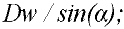
- In further embodiments, a method for differential traction drive and steering axis coordination for an autonomous device includes a pivot point location Dp substantially equal to Dw / sin(α), where Dw is the distance between the front roller and the steering axle, and α is the steering angle.
- In yet further embodiments, a computer implemented method for differential traction drive and steering axis coordination for an autonomous device includes for a clockwise turn, the value of right wheel ending speed Vre is substantially equal to Vf * (Dp - Dsr) IDp, where Vf is the target forward speed, Dp is the distance from the pivot point location to the steering axle, and Dsr is the distance from the steering axle to the center of the right wheel, and the value of left wheel ending speed Vle is substantially equal to Vf * (Dp + Dsl) IDp, where Vf is the target forward speed, Dp is the distance from the pivot point location to the steering axle, and Dsl is the distance from the steering axle to the center of the left wheel.
- In an embodiment, a computer implemented method for differential traction drive and steering axis coordination for an autonomous device includes determining a left wheel transitional speed based on the determined left wheel starting speed, the determined left wheel ending speed, and a difference between a current steering angle associated with the autonomous device and a target steering angle; and subsequent to applying the left wheel starting speed and the right wheel starting speed, and prior to applying the left wheel ending speed and the right wheel ending speed, applying the left wheel transitional speed and the right wheel transitional speed.
- In further embodiments, a computer implemented method for differential traction drive and steering axis coordination for an autonomous device includes applying the left wheel transition speed and right wheel transition speed when the difference between the current steering angle and the target steering angle is less than a predetermined threshold angle.
- In an embodiment, a computer implemented method for differential traction drive and steering axis coordination for an autonomous device includes the steering rotational speed driven by a steering motor.
- In further embodiments, a computer implemented method for traction control for a turf device having at least one wheel for providing motion on a ground surface includes detecting a wheel slip event, and responsive to the wheel slip event, stopping motion of the wheel and then gradually increasing a wheel speed, detecting a further wheel slip event, stopping motion of the wheel, determining that a steering angle of the wheel is less than or equal to a predetermined maximum steering angle and adjusting the steering angle of the wheel, gradually increasing the wheel speed while the steering angle is less than or equal to a predetermined maximum steering angle.
- In an embodiment, a computer implemented method for traction control of claim 10, wherein adjusting a steering angle of the wheel comprises adjusting the steering angle to a first defined value.
- In an embodiment, a computer implemented method for traction control includes subsequent to adjusting the steering angle to a first defined value, adjusting the steering angle to a second defined value opposite to the first defined value, gradually increasing the wheel speed.
- In an embodiment, a computer implemented method for traction control includes increasing a first defined angle in successive iterations, wherein the second defined angle is opposite to the first defined angle.
- In an embodiment, a computer implemented method for traction control includes stopping operation of the turf device when the steering angle exceeds a predetermined maximum steering angle.
- In an embodiment, a computer implemented method for traction control includes determining the steering angle based on data associated with the weight distribution of the turf device.
- In an embodiment, a computer implemented method for traction control for a turf device having a motor for driving two or more traction wheels providing motion over a ground surface includes measuring a motor current, calculating an expected motor current, detecting a wheel slip condition based on a comparison of the measured motor current to the calculated motor current.
- In an embodiment, a computer implemented method for traction control for a turf device includes calculating at least one of an expected linear velocity, linear acceleration, rotational velocity, and/or rotational acceleration associated with the turf device, calculating an expected linear velocity, linear acceleration, rotational velocity, and/or rotational acceleration associated with the turf device, measuring linear velocity, linear acceleration, rotational velocity, and/or rotational acceleration associated with the turf device, and detecting a wheel slip condition based on a comparison of the measured linear velocity, linear acceleration, rotational velocity, and/or rotational acceleration to the calculated linear velocity, linear acceleration, rotational velocity, and/or rotational acceleration.
- To accomplish the foregoing and related ends, certain illustrative aspects of the disclosure are described herein in connection with the following description and the drawings. These aspects are indicative, however, of but a few of the various ways in which the principles of the disclosure can be employed and the subject disclosure is intended to include all such aspects and their equivalents. Other advantages and features of the disclosure will become apparent from the following detailed description of the disclosure when considered in conjunction with the drawings.
-
-
FIG. 1 is an illustration of an example system for differential traction drive with steering axis coordination in accordance with an aspect of the disclosure. -
FIG. 2 is an illustration of an example system for differential traction drive with steering axis coordination in accordance with an aspect of the disclosure. -
FIG. 3 is an illustration of an example system for differential traction drive with steering axis coordination in accordance with an aspect of the disclosure. -
FIG. 4 is an illustration of an example system for differential traction drive with steering axis coordination in accordance with an aspect of the disclosure. -
FIG. 5 is an illustration of an example system for differential traction drive with steering axis coordination in accordance with an aspect of the disclosure. -
FIG. 6 is an illustration of an example system for differential traction drive with steering axis coordination in accordance with an aspect of the disclosure. -
FIG. 7 is an example flow chart of operations for differential traction drive with steering axis coordination in accordance with an aspect of the disclosure. -
FIG. 8 is an example flow chart of operations for differential traction drive with steering axis coordination in accordance with an aspect of the disclosure. -
FIG. 9 is an example flow chart of operations for differential traction drive with steering axis coordination in accordance with an aspect of the disclosure. - It should be noted that all the drawings are diagrammatic and not drawn to scale. Relative dimensions and proportions of parts of the figures have been shown exaggerated or reduced in size for the sake of clarity and convenience in the drawings. The same reference numbers are generally used to refer to corresponding or similar features in the different embodiments. Accordingly, the drawings and description are to be regarded as illustrative in nature and not as restrictive.
- The following terms are used throughout the description, the definitions of which are provided herein to assist in understanding various aspects of the subject disclosure.
- As used herein, the terms "autonomous mower", "device", "turf device", "robotic mower", "vehicle" and "robot" refer to an autonomous robot, or most any autonomous device, vehicle or machine that performs various tasks and functions including lawn mowing, lawn maintenance, vacuum cleaning, floor sweeping and the like. Similarly, and as used herein, the terms "autonomous mower", "robotic mower", "vehicle", "turf device", "device" and "robot" are used interchangeably and refer to most any device, or machine that utilizes both traction and steering mechanisms, wherein the device or machine is not necessarily autonomous.
- The term "traction drum" can include multiple traction wheels, e.g., front, rear, left and/or right traction wheels. The individual traction wheels may be independently controlled by the turf device.
- In the following description, for purposes of explanation, numerous specific details are set forth in order to provide a thorough understanding of the subject disclosure. It may be evident, however, that the disclosure can be practiced without these specific details. In other instances, well-known structures and devices are shown in block diagram form in order to facilitate describing the disclosure.
- The disclosed technology can include multiple traction motors, for example, a separate traction motor can be associate with each traction wheel. During a steering operation, for example, when the turf device turns left, the steering turns in a clockwise motion. Because the turf device includes two independent traction motors, the turf device can coordinately command both wheel speeds so that the left wheel rotates forward, and right wheel rotates backwards to assist the steering motor. This coordination allows the required torque from the steering motor to be greatly reduced. The disclosed technology provides robust, continuous steering operation when compared to turf devices or vehicles having similar locomotion designs.
- Advantages of the differential traction drive with steering axis coordination include less stress on the steering motor, faster response for the turn motion, provides a flexible, dynamic implementation of a "differential lock" type feature via software, without additional mechanical components; and better traction control when stuck due to an obstacle such as an irrigation pod, or a sprinkler head.
- In other embodiments, where no steering motor is included, the wheel traction motor(s) can be utilized to control the steering and traction at the same time.
- Referring to
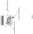
FIG. 1 , a top view block diagram of aturf device 100 is shown, including aturf device chassis 102,front roller 104, a traction drum including aleft traction wheel 106 and aright traction wheel 108, asteering axle 110, asteering motor 112, an indication of the leftwheel motion direction 114, an indication of theright wheel motion 116, and an indication of the direction ofmovement 118 of theturf device 100. - A drive section (not shown) is connected to steering
axle 110 and asteering motor 112 to pivot and direct motion of theleft traction wheel 106 andright traction wheel 108 during operation, thus allowing theturf device 100 to alter its path during movement. - Referring to
FIG. 2 , a side view of theturf device 100 is shown, including therobot chassis 102,front roller 104,traction wheels shaft 110, steeringmotor 112, androbot motion direction 118. - Referring to
FIG. 3 , during a steering operation, for example, theturf device 100 turns left, the steering mechanism turns in a clockwise motion. When theturf device 100 is making a left turn, and theback wheel assemblies right wheels - As shown in
FIG. 4 , once a desired steering angle is achieved, the left andright wheels turf device 100 to turn left. The ratio ofleft wheel speed 122 and theright wheel speed 124 can be calculated based on the desired turning radius. - Referring to
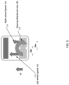
FIG. 5 , the differential traction drives for each traction wheel are coordinated to assist the steering. -
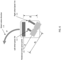
FIG. 6 is an illustration of the steering causing theturf device 100 to turn in a counter-clockwise direction. - Referring to
FIG. 7 , an example flow chart of operations for differential traction drive with steering axis coordination in accordance with an aspect of the disclosure is illustrated. -
FIG. 8 is an example flow chart of operations for differential traction drive with steering axis coordination in accordance with an aspect of the disclosure, including detection of traction issues. -
FIG. 9 is an example flow chart of operations for differential traction drive with steering axis coordination in accordance with an aspect of the disclosure, including an example traction control scheme. - Referring to
Fig. 3 andFig. 4 , during the turning motion, from the starting to the end, the desired speed of the right wheel will change in scale and also changes in the rotational direction. To smoothly change the wheel speeds, a coordination algorithm can be described as follows: - In an embodiment, at the start of the steering motion, to steer the
turf device 100 to a desired angle α, and when α is larger than a threshold angle β, can be derived, for example, as: - assuming the target
overall turf device 100 forward speed is Vf(m/s); - the steering rotational speed is, Ws, which is driven by the
steering motor 112 112 and with the traction wheels (rad./sec.); and - the distance from the steering axle to the center of the left wheel, Dsl (m), which is the same to the right wheel, Dsr (m).
- To match the steering rotational speed, the starting
left wheel speed 122, Vis, and the rightwheel starting speed 124, Vrs are obtained as:


- When applying Vls and Vrs, the steering assembly begins to turn. The overall coordination is shown in
Fig. 5 . - In an embodiment, at the ending of the steering motion, when reaching the desired steering angle, the ending speed of left wheel Vle, and the right wheel speed Vre can be determined by the following processes:
- As shown in
Fig. 6 , the terms are calculated and defined as follows:

- Where Dw is the distance between the front roller and the steering axle, α is the steering angle, and Dp is the distance from the pivot point to the steering axle. The distance between the front roller and the steering axle can measured from either of a center point, or a leading or trailing edge of the front roller and the steering axle, depending upon for example, the physical configuration of the front roller and the steering axle.
- When the steering assembly turns counter-clockwise (α > 0):


- When the steering assembly turns clockwise and (α < 0):


- In an embodiment, the transition between starting and ending a steering motion is achieved as follows:
The transition wheel speeds can be applied in between the starting and ending steering motions when the differences angle, γ, between the current steering angle and the desired steering angle α is less than a pre-set threshold angle β.

- By applying the equations above, the wheel speeds gradually change from the start of the steering motion to the end of the motion, while maintaining the overall motion speed.
- The disclosed system can include two traction motors, or a traction motor for each traction wheel, and a
steering motor 112. In aspects, the disclosed system is overconstrained when compared to conventional systems including a single traction motor, and an open differential. This presents a challenge when optimizing the system, which is addressed by the algorithms disclosed herein, and which rely at least in part on the speed commanded to the motors, and in aspects, speed feedback from the motors. Additional variables can be considered, for example, the current draw of the motors, as well as additional knowledge associated with the dynamics of the system, theautonomous turf device 100, the operating environment, and/or the external terrain. For example, if the external terrain, or the ground surrounding the turf device, slopes in a particular direction, the traction wheels can be directed so that the force of gravity aids in the movement of theturf device 100. - In embodiments, sensors can be utilized to gather data concerning the operation and steering of the
turf device 100. The additional sensors can be included in the body or structure of theturf device 100, can be remote to theturf device 100, or can be located within a work area, or remote to the work area. For example, data can be obtained from rotational encoders, tachometer, gyroscope, accelerometers, inertial measurement unit, odometer, velocity meter, global positioning system (GPS), Light Detection and Ranging (LIDAR), ultra-wideband radar, beaconing systems, Global System for Mobile Communications (GSM) localization, or most any other systems and sensors, and can be combined with data received via sensors included on theturf device 100. - A
processing component 122 includes hardware, software, and/or firmware components configured to receive, sample, filter, convert, process and use data, for example, data associated with the differential traction drive with steering axis coordination systems, and other sensors and inputs. - In an embodiment,
processing component 122 includes a microprocessor, data processing hardware and software, memory, and other associated hardware, software and algorithms for differential traction drive with steering axis coordination systems of theturf device 100.Processing component 122 can perform operations associated with analog to digital signal conversion, signal sampling, signal filtering, execution of the disclosed algorithms, and other algorithms, evaluation of data, information determination, location determination, and most any other function related to differential traction drive with steering axis coordination. - The disclosed differential traction drive with steering axis coordination systems and methods can be implemented as "computer readable instructions", algorithms and/or modules for execution by the
processing component 122. Computer readable instructions can be provided as program modules, such as functions, objects, Application Programming Interfaces (APIs), data structures, and the like, that perform particular tasks or implement particular abstract data types. - In further embodiments, the disclosed system and method can function in a mode in the event the
turf device 100 becomes stuck, or starts slipping. The combined system can be re-optimized with the goal of maximizing tractive force whereby it temporarily foregoes the goal of achieving a particular traction speed and focuses on regaining traction. For example, the steering is set straight and theturf device 100 smoothly accelerates both traction motors, so they match speed. Other embodiments can utilize a kinematic model of the system including weight distribution as well as a model for the terrain to maximize the tractive force applied by theturf device 100 to the ground. - In an embodiment, when the external terrain, or the ground surrounding the turf device, slopes in a particular direction, the traction wheels can be directed so that the force of gravity aids in the movement of the
turf device 100. Likewise, data associated with the weight distribution of theturf device 100 can be used in determining a steering angle. - In an embodiment, a computer implemented method for traction control for a
turf device 100 having at least one traction wheel for providing motion on a ground surface includes detecting a wheel slip event, and responsive to the wheel slip event, stopping motion of the wheel and then gradually increasing a wheel speed, detecting a wheel slip event, stopping motion of the wheel, determining if a steering angle of the wheel is less than or equal to a predetermined maximum steering angle and adjusting a steering angle of the wheel, and gradually increasing the wheel speed while the steering angle is less than or equal to a predetermined maximum steering angle. - Adjusting a steering angle of the wheel can include adjusting the steering angle to a first defined value. The steering angle can be adjusted to a second defined value that is opposite to the first defined value subsequent to adjusting the steering angle to the first defined value, and then gradually increasing wheel speed and detecting a wheel slip event. The number of defined values (first, second, third, ... values) can be subject to the applications. A greater number of defined values causes the
turf device 100 to make successive attempts to regain traction. The first defined angle can be increased in successive iterations, and the second defined angle can be opposite to the first defined angle. - In an embodiment, a computer implemented method for detecting wheel slip for a
turf device 100 having at least onewheel turf device 100, calculating an expectedturf device 100 motor current, determining a wheel slip condition based on a comparison of the measured motor current to the calculated device motor current. - In further embodiments, a computer implemented method for detecting wheel slip for a
turf device 100 having at least onewheel turf device 100, measuring a rotational velocity associated with theturf device 100, calculating an expected linear velocity and acceleration associated with theturf device 100, calculating an expected rotational velocity and acceleration associated with theturf device 100, determining a wheel slip condition based on a comparison of the measured linear velocity and accelerations associated with theturf device 100 to the calculated linear velocity and accelerations associated with theturf device 100, and determining a wheel slip condition based on a comparison of the measured rotational velocity associated with theturf device 100 to the calculated rotational velocity associated with theturf device 100. -
FIG. 7 illustrates amethod 700 for differential traction drive with steering axis coordination in accordance with aspects of the disclosure. Themethod 700 begins atact 702 where the steering axis coordination method begins. Atact 704, the method can include initiating a steering motion based on a target turf vehicle forward speed, and a steering rotational speed. The steering rotational speed (or angular velocity) 124 can be driven by asteering motor 112 and the traction wheel (e.g., rad./sec.) associated with the turf vehicle. Example calculations for use in connection themethod 700 are described in detail supra. - At
act 706, a left wheel starting speed Vls and a right wheel starting speed Vlr can be determined and applied. The starting wheel speeds can be determined based on, for example, the target forward speed, a distance from a steering axle to the center of the respective wheel, and the steering rotational speed. - At
act 708, the turf vehicle is a left wheel transition speed Vlt and a right wheel transition speed Vlt can be determined and applied, based on for example, the respective starting and ending wheel speeds, and the differences between the current steering angle and the desired steering angle. In an embodiment, the left and right wheel transition speeds are calculated and applied when the difference between the current steering angle and the desired steering angle is less than a predetermined threshold angle. - At
act 710, the turf vehicle is a left wheel ending speed Vle and a right wheel ending speed Vle can be determined and applied, based on for example, the desired turf device speed, a distance from the steering axle to the center of the respective wheel, and a distance from the pivot point to the steering axle. The pivot point can be calculated based on the distance from the front roller to the steering axle, and the desired steering angle. - The application of the starting wheel speeds, the transition wheel speeds, and the ending wheel speeds as detailed above provide a coordinated steering motion wherein the left and right wheel speeds gradually change from the start of the steering motion to the end of the motion, while maintaining the overall motion speed of the
turf device 100. -
FIG. 8 illustrates amethod 800 for differential traction drive with steering axis coordination in accordance with aspects of the disclosure. In an embodiment, the disclosed method solves problems associated with traction issues, such as wheel slippage and wheel spinning. Significant damage to the turf can be caused by spinning/slipping of the traction wheels or drums on the turf. The disclosed method of traction control lessens or prevents spinning/slipping of the traction wheels thus lessening or preventing damage to the turf. Further, two independent traction motors allow theturf device 100 to control the individual traction motors to re-gain traction and minimize turf wear when one of the traction wheels is slipping. - The
method 800 can be utilized to identify a traction issue by detecting, for example, wheel slip. Wheel slippage can be detected by determining an amount of electrical current applied to the motors. When a traction wheel is slipping/spinning on the turf, the current drawn by the motor will be less than expected. In an embodiment, traction wheel slipping/spinning can also be detected by determining the motion of theturf device 100 with respect to the steering angle and traction drum speed. In further embodiments, traction wheel slipping and/or spinning can be detected utilizing a measurement of the turf device's linear velocity and rotational velocity and a kinematics model of theturf device 100, and/or a measurement of the turf device's linear acceleration and rotational acceleration and a dynamics model of theturf device 100. For example, a kinematics model of theturf device 100 is utilized to estimate the turf device's linear velocity and rotational velocity with the commanded drum steering angle and drum speed, and a dynamics model of theturf device 100 is utilized to estimate the turf device's linear acceleration and rotational acceleration with the commanded traction drum steering angle and traction drum speed. - The present motion of the
turf device 100 in linear velocity, rotational velocity and accelerations can be measured using sensors such as GPS, IMU LiDAR and/or AHRS, and the like. An estimatedturf device 100 response and the measured result are compared to determine if theturf device 100 is experiencing slipping or spinning of the traction wheel or wheels. With reference toFIG. 8 , themethod 800 begins atstep 802 where the expected motor current draw is calculated utilizing, for example, a motor and load model. Atstep 804, expectedturf device 100 velocities and accelerations are determined utilizing an inverse kinematics model, an inverse dynamics model and/or information on the motion commands provided to theturf device 100, for example, the traction drum steering angle and traction drum speed commanded or controlled by theturf device 100. - At
act 806, a measurement of the motor current is obtained. The measured motor current is compared to the expected motor current atstep 810. - Still referring to
FIG. 8 , atstep 808 the linear and rotational velocities and/or the linear and rotational accelerations of theturf device 100 are measured. The estimated linear and rotational velocities and/or the estimated linear and rotational accelerations of theturf device 100 are compared with the measured linear and rotational velocities and/or measured estimated linear and rotational accelerations of theturf device 100 atstep 812. Atstep 814, spinning or slip of the traction wheel is determined based on the comparisons of the measured current draw, linear and rotational velocities, and/or linear and rotational accelerations to the expected or calculated current draw, linear and rotational velocities, and/or linear and rotational accelerations. - In aspects, the measurements and comparisons performed at
steps step 814. The comparison atstep 814 can be conducted utilizing the weighted or averaged motor current measurements, and/or weighted or averaged linear and rotational velocity measurements, and linear and rotational acceleration measurements obtained atsteps - In an embodiment, traction wheel slip is indicated when the measured motor current differs from an expected motor current by a predetermined threshold. In aspects, traction wheel slip is indicated when the measured
turf device 100 velocities and accelerations differ from the estimated linear and/or rotational velocities and the estimated linear and/or rotational accelerations of theturf device 100 by a predetermined threshold. In other embodiments, a combination of the data from the comparison of the measured motor current to an expected motor current and data from a comparison of the measuredturf device 100 velocities and accelerations to the estimated or calculated velocities and accelerations of theturf device 100 is used to determine traction wheel slip. -
FIG. 9 illustrates an exampletraction control method 900. When traction wheel slippage has been detected, forexample utilizing method 800, theturf device 100 can perform a traction control method to re-gain wheel traction. With reference toFIG. 9 , atraction control method 900 can include step 902 where a speed command that slows down the wheel speed, or a brake command is applied to the traction wheel that has been determined to be slipping. By matching the turf device's measured rotational wheel speeds and the motor current, theturf device 100 can gain increased traction in each individual traction drum. - If no traction issues are detected, for
example utilizing method 800, theturf device 100 resumes normal operation atstep 906. If theturf device 100 remains stuck, i.e. one or more wheels are indicated as slipping, the drum can be stopped, and then the drum speed gradually increased to exploit greater traction, for example in the form of static fraction, atstep 904. As instep 902, if no traction issue is detected, theturf device 100 resumes normal operation atstep 906, and themethod 900 ends atstep 918. - If the
turf device 100 continues to remain stuck, theturf device 100 can perform one or more maneuvers to break free. Atstep 908, the wheel is stopped and then turned or steered in a defined angle based on, for example, a measured incline. Motion of the wheel is then gradually re-started. If no traction issue is detected subsequent to the maneuver ofstep 908, theturf device 100 resumes normal operation atstep 906, and themethod 900 ends atstep 918. - If the
turf device 100 continues to remain stuck, theturf device 100 can perform the maneuver ofstep 910 where the wheel drum is stopped, and then steered in an angle opposite to, or different from, the defined angle instep 908. The wheel is then engaged and driven at a relatively low speed to exploit static fraction present between the wheel and the ground, or obstacle. For example, if wheel slip is indicated afterstep 908 at a steering angle of 30 degrees, then the wheel can be turned to -30 degrees atstep 910, and the wheel speed gradually increased to avoid slippage. If no traction issue is detected subsequent to the maneuver ofstep 910, theturf device 100 resumes normal operation atstep 906, and themethod 900 ends atstep 918. - While the
turf device 100 remains stuck, theturf device 100 can perform the maneuver ofstep 912 where each wheel drum is stopped and then steered in an angle different from its present steering angle, and then the wheel speed gradually increased. In an embodiment, the steering angle ofstep 912 is increased when compared to the steering angle ofstep 910. - For example, if the wheel remains stuck at -30 degrees, the wheel is turned to 45 degrees, and then -45 degrees, and so on. The wheel is engaged at each successive angle, and the wheel speed is gradually increased to avoid slippage. If no traction issues are detected subsequent to the maneuvers of
step 912, theturf device 100 resumes normal operation atstep 906, and themethod 900 ends atstep 918. - The maneuvers of
steps step 914, and at which point operation of theturf device 100 is halted 916 and themethod 900 ends atstep 918. - While, for purposes of simplicity of explanation, the methodology illustrated in
FIGS. 7-9 is shown and described as a series of acts or steps, it is to be understood and appreciated that the subject disclosure is not limited by the order of acts or steps, as some acts may, in accordance with the disclosure, occur in a different order and/or concurrently with other acts from that shown and described herein. For example, those skilled in the art will understand and appreciate that a methodology could alternatively be represented as a series of interrelated states or events, such as in a state diagram. Moreover, not all illustrated acts or steps may be required to implement a methodology in accordance with the disclosure. - While embodiments of the disclosed differential traction drive with steering axis coordination systems and methods have been described, it should be understood that the differential traction drive with steering axis coordination systems and methods are not so limited and modifications may be made without departing from the disclosed differential traction drive with steering axis coordination systems and methods. The scope of the differential traction drive with steering axis coordination systems and methods are defined by the appended claims, and all turf devices, processes, and methods that come within the meaning of the claims, either literally or by equivalence, are intended to be embraced therein.
- The invention may provide a computer implemented method in accordance with any one of the following numbered clauses, which, for the avoidance of doubt, do not constitute part of the claims of this application.
- 1. A computer implemented method for differential traction drive and steering axis coordination for an autonomous device, comprising:
- initiating a steering motion based on a target autonomous device speed, and a steering rotational speed,
- determining a left wheel starting speed based on the target autonomous device speed, a distance from a steering axle associated with the autonomous device to a center of the left traction wheel, and the steering rotational speed;
- determining a right wheel starting speed based on the target autonomous device speed, a distance from the steering axle to a center of the right traction wheel, and the steering rotational speed; and
- applying the left wheel starting speed and the right wheel starting speed.
- 2. The computer implemented method for differential traction drive and steering axis coordination for an autonomous device of clause 1, comprising:
- determining a left wheel ending speed based on the target forward speed, the distance from the steering axle to the center of the left wheel, and a pivot point location, wherein the pivot point location is calculated based at least in part on a distance from a front roller of the autonomous device to the steering axle;
- determining a right wheel ending speed based on the target forward speed, the distance from the steering axle to the center of the right wheel, and the pivot point location; and
- subsequent to applying the left wheel starting speed and the right wheel starting speed, applying the left wheel ending speed and the right wheel ending speed.
- 3. The computer implemented method for differential traction drive and steering axis coordination for an autonomous device of clause 2, wherein for a counter-clockwise turn, the value of the left wheel ending speed Vle is substantially equal to

- 4. The computer implemented method for differential traction drive and steering axis coordination for an autonomous device of clause 2 or clause 3, wherein for a counter-clockwise turn, the value of right wheel ending speed Vre is substantially equal to

- 5. The computer implemented method for differential traction drive and steering axis coordination for an autonomous device of any of clauses 2 to 4, wherein the pivot point location Dp is substantially equal to
- 6. The computer implemented method for differential traction drive and steering axis coordination for an autonomous device of any of clauses 2 to 5, wherein for a clockwise turn,
- the value of right wheel ending speed Vre is substantially equal to

- the value of left wheel ending speed Vle is substantially equal to

- the value of right wheel ending speed Vre is substantially equal to
- 7. The computer implemented method for differential traction drive and steering axis coordination for an autonomous device of any of clauses 2 to 6, comprising:
- determining a left wheel transitional speed based on the determined left wheel starting speed, the determined left wheel ending speed, and a difference between a current steering angle associated with the autonomous device and a target steering angle; and
- subsequent to applying the left wheel starting speed and the right wheel starting speed, and prior to applying the left wheel ending speed and the right wheel ending speed, applying the left wheel transitional speed and the right wheel transitional speed.
- 8. The computer implemented method for differential traction drive and steering axis coordination for an autonomous device of clause 7, comprising:
applying the left wheel transition speed and right wheel transition speed when the difference between the current steering angle and the target steering angle is less than a predetermined threshold angle. - 9. The computer implemented method for differential traction drive and steering axis coordination for an autonomous device of any of clauses 1 to 8, wherein the steering rotational speed is driven by a steering motor.
- 10. A computer implemented method for traction control for a turf device having at least one wheel for providing motion on a ground surface, comprising:
- detecting a wheel slip event;
- responsive to the wheel slip event, stopping motion of the wheel and then gradually increasing a wheel speed;
- detecting a wheel slip event;
- stopping motion of the wheel;
- i) adjusting the steering angle of the wheel; and
- ii) gradually increasing the wheel speed while the steering angle is less than or equal to a predetermined maximum steering angle.
- 11. The computer implemented method for traction control of clause 10, wherein adjusting a steering angle of the wheel comprises adjusting the steering angle to a first defined value.
- 12. The computer implemented method for traction control of clause 11, comprising:
- subsequent to adjusting the steering angle to a first defined value, adjusting the steering angle to a second defined value opposite to the first defined value; and
- gradually increasing the wheel speed.
- 13. The computer implemented method for traction control of clause 11 or clause 12, wherein the first defined angle is increased in successive iterations, and wherein the second defined angle is opposite to the first defined angle.
- 14. The computer implemented method for traction control of any of clauses 10 to 13, comprising stopping operation of the turf device when the steering angle exceeds a predetermined maximum steering angle.
- 15. The computer implemented method for traction control of any of clauses 10 to 14, wherein the steering angle is determined based on data associated with the weight distribution of the turf device.
- 16. A computer implemented method for traction control for a turf device having a motor for driving two or more traction wheels providing motion over a ground surface, comprising:
- measuring a motor current;
- calculating an expected motor current;
- detecting a wheel slip condition based on a comparison of the measured motor current to the calculated motor current.
- 17. The computer implemented method for traction control for a turf device of clause 16, comprising:
- calculating an expected linear velocity associated with the turf device;
- calculating an expected linear acceleration associated with the turf device;
- measuring a linear velocity associated with the turf device;
- measuring a linear acceleration associated with the turf device; and
- detecting a wheel slip condition based on a comparison of the measured linear velocity to the calculated linear velocity and a comparison of the measured linear acceleration to the calculated linear acceleration.
- 18. The computer implemented method for traction control for a turf device of clause 16 or clause 17, comprising:
- calculating an expected rotational acceleration associated with the turf device;
- calculating an expected linear acceleration associated with the turf device;
- measuring a rotational acceleration associated with the turf device;
- measuring a linear acceleration associated with the turf device; and
- detecting a wheel slip condition based on a comparison of the measured rotational acceleration to the calculated rotational acceleration and a comparison of the measured linear acceleration to the calculated linear acceleration.
- 19. The computer implemented method for traction control for a turf device of any of clauses 16 to 18, comprising:
- calculating an expected rotational velocity associated with the turf device;
- calculating an expected rotational acceleration associated with the turf device;
- measuring a rotational velocity associated with the turf device;
- measuring a rotational acceleration associated with the turf device; and
- detecting a wheel slip condition based on a comparison of the measured rotational velocity to the calculated rotational velocity and a comparison of the measured rotational acceleration the calculated rotational acceleration.
- 20. The computer implemented method for traction control for a turf device of any of clauses 16 to 19, comprising:
- calculating an expected linear velocity associated with the turf device;
- calculating an expected rotational velocity associated with the turf device;
- measuring a linear velocity associated with the turf device;
- measuring a rotational velocity associated with the turf device; and
- detecting a wheel slip condition based on a comparison of the measured linear velocity associated with the device to the calculated linear velocity associated with the device and a comparison of the measured rotational velocity to the calculated rotational velocity.
Claims (11)
- A computer implemented method for traction control for a turf device having at least one wheel for providing motion on a ground surface, comprising:detecting a wheel slip event;responsive to the wheel slip event, stopping motion of the wheel and then gradually increasing a wheel speed;detecting a wheel slip event;stopping motion of the wheel;determining that a steering angle of the wheel is less than or equal to a predetermined maximum steering angle andi) adjusting the steering angle of the wheel; andii) gradually increasing the wheel speed while the steering angle is less than or equal to a predetermined maximum steering angle.
- The computer implemented method for traction control of claim 1, wherein adjusting a steering angle of the wheel comprises adjusting the steering angle to a first defined value.
- The computer implemented method for traction control of claim 2, comprising:subsequent to adjusting the steering angle to a first defined value, adjusting the steering angle to a second defined value opposite to the first defined value; andgradually increasing the wheel speed.
- The computer implemented method for traction control of claim 2 or claim 3, wherein the first defined angle is increased in successive iterations, and wherein the second defined angle is opposite to the first defined angle.
- The computer implemented method for traction control of any one of the preceding claims, comprising stopping operation of the turf device when the steering angle exceeds a predetermined maximum steering angle.
- The computer implemented method for traction control of any one of the preceding claims, wherein the steering angle is determined based on data associated with the weight distribution of the turf device.
- The computer implemented method for traction control of any one of the preceding claims, wherein the turf device has a motor for driving two or more traction wheels providing motion over a ground surface, and wherein detecting a wheel slip event comprises:measuring a motor current;calculating an expected motor current;detecting a wheel slip condition based on a comparison of the measured motor current to the calculated motor current.
- The computer implemented method for traction control for a turf device of claim 7, wherein detecting a wheel slip event further comprises:calculating an expected linear velocity associated with the turf device;calculating an expected linear acceleration associated with the turf device;measuring a linear velocity associated with the turf device;measuring a linear acceleration associated with the turf device; anddetecting a wheel slip condition based on a comparison of the measured linear velocity to the calculated linear velocity and a comparison of the measured linear acceleration to the calculated linear acceleration.
- The computer implemented method for traction control for a turf device of claim 7, wherein detecting a wheel slip event further comprises:calculating an expected rotational acceleration associated with the turf device;calculating an expected linear acceleration associated with the turf device;measuring a rotational acceleration associated with the turf device;measuring a linear acceleration associated with the turf device; anddetecting a wheel slip condition based on a comparison of the measured rotational acceleration to the calculated rotational acceleration and a comparison of the measured linear acceleration to the calculated linear acceleration.
- The computer implemented method for traction control for a turf device of claim 7, wherein detecting a wheel slip event further comprises:calculating an expected rotational velocity associated with the turf device;calculating an expected rotational acceleration associated with the turf device;measuring a rotational velocity associated with the turf device;measuring a rotational acceleration associated with the turf device; anddetecting a wheel slip condition based on a comparison of the measured rotational velocity to the calculated rotational velocity and a comparison of the measured rotational acceleration the calculated rotational acceleration.
- The computer implemented method for traction control for a turf device of claim 7, wherein detecting a wheel slip event further comprises:calculating an expected linear velocity associated with the turf device;calculating an expected rotational velocity associated with the turf device;measuring a linear velocity associated with the turf device;measuring a rotational velocity associated with the turf device; anddetecting a wheel slip condition based on a comparison of the measured linear velocity associated with the device to the calculated linear velocity associated with the device and a comparison of the measured rotational velocity to the calculated rotational velocity.
Applications Claiming Priority (3)
| Application Number | Priority Date | Filing Date | Title |
|---|---|---|---|
| US201862774279P | 2018-12-02 | 2018-12-02 | |
| PCT/US2019/063931 WO2020117640A2 (en) | 2018-12-02 | 2019-12-02 | Differential traction drive with steering axis coordination system and method |
| EP19828936.5A EP3887226B1 (en) | 2018-12-02 | 2019-12-02 | Differential traction drive with steering axis coordination system and method |
Related Parent Applications (2)
| Application Number | Title | Priority Date | Filing Date |
|---|---|---|---|
| EP19828936.5A Division-Into EP3887226B1 (en) | 2018-12-02 | 2019-12-02 | Differential traction drive with steering axis coordination system and method |
| EP19828936.5A Division EP3887226B1 (en) | 2018-12-02 | 2019-12-02 | Differential traction drive with steering axis coordination system and method |
Publications (2)
| Publication Number | Publication Date |
|---|---|
| EP4534391A2 true EP4534391A2 (en) | 2025-04-09 |
| EP4534391A3 EP4534391A3 (en) | 2025-06-25 |
Family
ID=69056135
Family Applications (2)
| Application Number | Title | Priority Date | Filing Date |
|---|---|---|---|
| EP19828936.5A Active EP3887226B1 (en) | 2018-12-02 | 2019-12-02 | Differential traction drive with steering axis coordination system and method |
| EP25158922.2A Pending EP4534391A3 (en) | 2018-12-02 | 2019-12-02 | Computer implemented method for traction control for a turf device |
Family Applications Before (1)
| Application Number | Title | Priority Date | Filing Date |
|---|---|---|---|
| EP19828936.5A Active EP3887226B1 (en) | 2018-12-02 | 2019-12-02 | Differential traction drive with steering axis coordination system and method |
Country Status (5)
| Country | Link |
|---|---|
| US (3) | US11565750B2 (en) |
| EP (2) | EP3887226B1 (en) |
| AU (1) | AU2019393755A1 (en) |
| CA (1) | CA3120590A1 (en) |
| WO (1) | WO2020117640A2 (en) |
Families Citing this family (18)
| Publication number | Priority date | Publication date | Assignee | Title |
|---|---|---|---|---|
| US11785885B2 (en) * | 2019-01-31 | 2023-10-17 | The Toro Company | Mower with ganged reel cutting units having automatic clip control in both straight ahead motion and in turns |
| US11654956B2 (en) * | 2019-12-23 | 2023-05-23 | Robert Bosch Gmbh | Method and system for steering intervention by electronic power steering unit to prevent vehicle rollover or loss of control |
| US11480434B2 (en) * | 2020-02-04 | 2022-10-25 | Pony Ai Inc. | Initial localization |
| US12296694B2 (en) | 2021-03-10 | 2025-05-13 | Techtronic Cordless Gp | Lawnmowers |
| CN115793627B (en) * | 2021-09-10 | 2026-04-14 | 威刚科技股份有限公司 | Power adjusting system and method for autonomous mobile device |
| US12443180B2 (en) | 2021-11-10 | 2025-10-14 | Techtronic Cordless Gp | Robotic lawn mowers |
| AU2023200381A1 (en) | 2022-01-31 | 2023-08-17 | Techtronic Cordless Gp | Robotic garden tool |
| EP4476598A2 (en) | 2022-02-07 | 2024-12-18 | Doosan Bobcat North America, Inc. | Path determination for automatic mowers |
| EP4270138A1 (en) | 2022-04-28 | 2023-11-01 | Techtronic Cordless GP | Creation of a virtual boundary for a robotic garden tool |
| US12472611B2 (en) | 2022-05-31 | 2025-11-18 | Techtronic Cordless Gp | Peg driver |
| EP4310621B1 (en) | 2022-07-19 | 2025-02-12 | Techtronic Cordless GP | Display for controlling robotic tool |
| AU2023206123A1 (en) | 2022-07-29 | 2024-02-15 | Techtronic Cordless Gp | Generation of a cryptography key for a robotic garden tool |
| US12466480B2 (en) * | 2022-10-05 | 2025-11-11 | Deere & Company | Radial differential speed control system |
| CN115857512A (en) * | 2022-12-15 | 2023-03-28 | 广东嘉腾机器人自动化有限公司 | A path tracking control method, device, and storage medium for a forklift AGV |
| CN118466478A (en) * | 2023-02-03 | 2024-08-09 | 浙江白马科技有限公司 | Autonomous operation equipment, control method thereof and autonomous operation system |
| US20250127080A1 (en) * | 2023-10-18 | 2025-04-24 | Mtd Products Inc | Power equipment device with operator-initiated automated limited turning apparatus |
| US12447829B2 (en) | 2023-12-19 | 2025-10-21 | Textron Innovations Inc. | Controlling vehicles based on current locations and current motion characteristics |
| WO2025162591A1 (en) * | 2024-02-02 | 2025-08-07 | Abb Schweiz Ag | Autonomous mobile robot |
Family Cites Families (32)
| Publication number | Priority date | Publication date | Assignee | Title |
|---|---|---|---|---|
| US3790871A (en) * | 1973-01-02 | 1974-02-05 | Gen Electric | Individual axle wheel slip control system |
| US5547038A (en) | 1991-08-01 | 1996-08-20 | Madwed; Albert | Wheeled chassis having independently pivotable drivewheels for omnidirectional motion |
| US5609220A (en) | 1992-08-27 | 1997-03-11 | Kabushiki Kaisha Komatsu Seisakusho | Operation control system for traveling vehicle |
| US6257357B1 (en) * | 1999-03-26 | 2001-07-10 | Deere & Company | Steering device for drive and steer transmission |
| DE19949351A1 (en) | 1999-10-13 | 2001-07-12 | Hanebeck Uwe D | Wheel module with at least one wheel; has drive motor with drive shaft and steering motor to steer wheel about steering angle, where one shaft is hollow and other shaft rotates in it |
| JP3919429B2 (en) | 2000-08-01 | 2007-05-23 | Tcm株式会社 | Work vehicle with traversing system |
| US6456925B1 (en) * | 2000-09-11 | 2002-09-24 | Deere & Company | Vehicle driven wheel speed control system |
| US6425450B1 (en) * | 2000-10-30 | 2002-07-30 | Lansberry Tractor Company, Inc. | Load-shifting vehicle |
| JP4131816B2 (en) * | 2002-12-27 | 2008-08-13 | 株式会社 神崎高級工機製作所 | Driving device for traveling vehicle |
| US7149611B2 (en) | 2003-02-21 | 2006-12-12 | Lockheed Martin Corporation | Virtual sensor mast |
| DE102004046890A1 (en) * | 2004-09-28 | 2006-03-30 | Jungheinrich Ag | Method for preventing tilting of rear-wheeled vehicles, in particular industrial trucks |
| DE102005057635B4 (en) * | 2005-12-02 | 2009-08-20 | Hochschule Ravensburg-Weingarten | vehicle |
| US20070295545A1 (en) | 2006-05-11 | 2007-12-27 | Romig Bernard E | Differential Steering and Traction Control For Electrically Propelled Mower |
| JP4820243B2 (en) * | 2006-08-31 | 2011-11-24 | 日立オートモティブシステムズ株式会社 | Automotive control device |
| US7778747B2 (en) * | 2006-08-31 | 2010-08-17 | National Railway Equipment Co. | Adhesion control system for off-highway vehicle |
| JP5423391B2 (en) * | 2009-12-28 | 2014-02-19 | 株式会社アドヴィックス | Vehicle speed control device |
| WO2012167836A1 (en) * | 2011-06-10 | 2012-12-13 | Alfred Kärcher Gmbh & Co. Kg | Self-propelled floor cleaning machine and method for operating a self-propelled floor cleaning machine |
| JP5808977B2 (en) * | 2011-08-19 | 2015-11-10 | Ntn株式会社 | Turning efficiency improvement device for vehicle yaw moment generation |
| US9778659B2 (en) * | 2012-09-10 | 2017-10-03 | Trimble Inc. | Agricultural autopilot steering compensation |
| EP2925205B1 (en) * | 2012-11-28 | 2017-05-10 | Alfred Kärcher GmbH & Co. KG | Self-propelled floor cleaning machine, and method for operating a self-propelled floor cleaning machine |
| US10149430B2 (en) * | 2013-02-20 | 2018-12-11 | Husqvarna Ab | Robotic work tool configured for improved turning in a slope, a robotic work tool system, and a method for use in the robot work tool |
| GB2512287B (en) * | 2013-03-22 | 2015-06-03 | Jaguar Land Rover Ltd | Improvements in vehicle steering |
| DE102014105163A1 (en) * | 2014-04-11 | 2015-10-15 | Claas Selbstfahrende Erntemaschinen Gmbh | Self-propelled harvester |
| JP2016060219A (en) * | 2014-09-12 | 2016-04-25 | アイシン精機株式会社 | Vehicle position detector |
| CN107428365B (en) * | 2015-02-25 | 2018-10-23 | 日本精工株式会社 | Electric power-assisted steering apparatus |
| US10836426B1 (en) * | 2015-04-06 | 2020-11-17 | Exmark Manufacturing Company, Incorporated | Active steering system and grounds maintenance vehicle including same |
| US9538706B2 (en) * | 2015-04-17 | 2017-01-10 | Deere & Company | Zero turn mower steering system |
| FR3037024B1 (en) * | 2015-06-08 | 2018-12-07 | Jtekt Europe | USE OF STEERING ASSISTANCE TO COMPENSATE NEGATIVE EFFECTS INDUCED BY LIMITED SLIP DIFFERENTIAL |
| JP6479627B2 (en) * | 2015-10-29 | 2019-03-06 | 株式会社クボタ | Electric work vehicle |
| US20170120922A1 (en) * | 2015-11-04 | 2017-05-04 | Mtd Products Inc | Maintenance vehicle |
| EP3457830B1 (en) * | 2016-05-19 | 2021-02-17 | Vermeer Manufacturing Company | Steered caster wheel systems |
| JP2018047827A (en) * | 2016-09-23 | 2018-03-29 | トヨタ自動車株式会社 | Steering control device |
-
2019
- 2019-12-02 EP EP19828936.5A patent/EP3887226B1/en active Active
- 2019-12-02 AU AU2019393755A patent/AU2019393755A1/en not_active Abandoned
- 2019-12-02 US US16/699,990 patent/US11565750B2/en active Active
- 2019-12-02 CA CA3120590A patent/CA3120590A1/en active Pending
- 2019-12-02 WO PCT/US2019/063931 patent/WO2020117640A2/en not_active Ceased
- 2019-12-02 EP EP25158922.2A patent/EP4534391A3/en active Pending
-
2023
- 2023-01-30 US US18/103,114 patent/US12441400B2/en active Active
-
2025
- 2025-07-16 US US19/271,136 patent/US20250340240A1/en active Pending
Also Published As
| Publication number | Publication date |
|---|---|
| EP3887226B1 (en) | 2025-04-02 |
| US12441400B2 (en) | 2025-10-14 |
| WO2020117640A2 (en) | 2020-06-11 |
| US20200172166A1 (en) | 2020-06-04 |
| US11565750B2 (en) | 2023-01-31 |
| US20250340240A1 (en) | 2025-11-06 |
| EP3887226A2 (en) | 2021-10-06 |
| AU2019393755A1 (en) | 2021-06-03 |
| EP4534391A3 (en) | 2025-06-25 |
| WO2020117640A3 (en) | 2020-08-20 |
| US20230174154A1 (en) | 2023-06-08 |
| CA3120590A1 (en) | 2020-06-11 |
Similar Documents
| Publication | Publication Date | Title |
|---|---|---|
| US12441400B2 (en) | Differential traction drive and steering axis coordination system and method | |
| Rankin et al. | Driving curiosity: Mars rover mobility trends during the first seven years | |
| EP3938260B1 (en) | Method for generating a setpoint for the combined control of a wheel-steering system and of a differential braking system of a motor vehicle | |
| US9380742B2 (en) | Autonomous implement | |
| EP3227169B1 (en) | All wheel drive robotic mower | |
| CN112405524B (en) | Robot collision detection method and device and robot | |
| US20170120755A1 (en) | Electric Work Vehicle | |
| US20220410853A1 (en) | Method for controlling propulsion of a heavy-duty vehicle | |
| EP3934947B1 (en) | A method for estimating vehicle motion state during a vehicle maneuver | |
| US11945443B2 (en) | Systems and methods for traction detection and control in a self-driving vehicle | |
| CN117799449A (en) | Lateral movement control method, vehicle and readable storage medium | |
| US20210055738A1 (en) | Self-propelled robot | |
| CN111358374A (en) | Detection method for robot walking along edge grinding bank and blocked detection and processing method | |
| JP2018120526A (en) | Travel control device, travel device, travel control method, and travel control program | |
| EP4461114A1 (en) | Detection of slip between a self-propelled robotic tool and a grass surface | |
| CN111481126B (en) | Robot walking along edge abnormity detection method and card-off processing method | |
| EP3102469B1 (en) | Method for monitoring the trajectory of a motor vehicle and associated vehicle | |
| US20240182107A1 (en) | Steering angle error monitoring | |
| US11787414B2 (en) | GPS enhanced friction estimation | |
| SE541115C2 (en) | Control system, and method in connection with a control system, for autonomous vehicles | |
| Ward et al. | Classification-based wheel slip detection and detector fusion for outdoor mobile robots | |
| JP7360993B2 (en) | Idling detection device and idling detection method | |
| US12447965B2 (en) | Method for stopping an autonomous vehicle | |
| US20260001559A1 (en) | Detection of yaw instabilities in vehicle combinations | |
| CN114537402A (en) | HJI theory-based 4WID-4WIS automobile path tracking control method and system |
Legal Events
| Date | Code | Title | Description |
|---|---|---|---|
| PUAI | Public reference made under article 153(3) epc to a published international application that has entered the european phase |
Free format text: ORIGINAL CODE: 0009012 |
|
| STAA | Information on the status of an ep patent application or granted ep patent |
Free format text: STATUS: THE APPLICATION HAS BEEN PUBLISHED |
|
| AC | Divisional application: reference to earlier application |
Ref document number: 3887226 Country of ref document: EP Kind code of ref document: P |
|
| AK | Designated contracting states |
Kind code of ref document: A2 Designated state(s): AL AT BE BG CH CY CZ DE DK EE ES FI FR GB GR HR HU IE IS IT LI LT LU LV MC MK MT NL NO PL PT RO RS SE SI SK SM TR |
|
| REG | Reference to a national code |
Ref country code: DE Ref legal event code: R079 Free format text: PREVIOUS MAIN CLASS: B62D0011000000 Ipc: B62D0005040000 |
|
| PUAL | Search report despatched |
Free format text: ORIGINAL CODE: 0009013 |
|
| AK | Designated contracting states |
Kind code of ref document: A3 Designated state(s): AL AT BE BG CH CY CZ DE DK EE ES FI FR GB GR HR HU IE IS IT LI LT LU LV MC MK MT NL NO PL PT RO RS SE SI SK SM TR |
|
| RIC1 | Information provided on ipc code assigned before grant |
Ipc: B62D 11/00 20060101ALI20250519BHEP Ipc: B62D 9/00 20060101ALI20250519BHEP Ipc: B62D 7/04 20060101ALI20250519BHEP Ipc: B62D 5/04 20060101AFI20250519BHEP |
|
| STAA | Information on the status of an ep patent application or granted ep patent |
Free format text: STATUS: REQUEST FOR EXAMINATION WAS MADE |
|
| 17P | Request for examination filed |
Effective date: 20251217 |