EP4534390A1 - Steuerungsvorrichtung für ein fahrzeuglenksystem - Google Patents
Steuerungsvorrichtung für ein fahrzeuglenksystem Download PDFInfo
- Publication number
- EP4534390A1 EP4534390A1 EP22943853.6A EP22943853A EP4534390A1 EP 4534390 A1 EP4534390 A1 EP 4534390A1 EP 22943853 A EP22943853 A EP 22943853A EP 4534390 A1 EP4534390 A1 EP 4534390A1
- Authority
- EP
- European Patent Office
- Prior art keywords
- gain
- value
- turning
- steering
- reaction force
- Prior art date
- Legal status (The legal status is an assumption and is not a legal conclusion. Google has not performed a legal analysis and makes no representation as to the accuracy of the status listed.)
- Pending
Links
Images












Classifications
-
- B—PERFORMING OPERATIONS; TRANSPORTING
- B62—LAND VEHICLES FOR TRAVELLING OTHERWISE THAN ON RAILS
- B62D—MOTOR VEHICLES; TRAILERS
- B62D6/00—Arrangements for automatically controlling steering depending on driving conditions sensed and responded to, e.g. control circuits
- B62D6/008—Control of feed-back to the steering input member, e.g. simulating road feel in steer-by-wire applications
-
- B—PERFORMING OPERATIONS; TRANSPORTING
- B62—LAND VEHICLES FOR TRAVELLING OTHERWISE THAN ON RAILS
- B62D—MOTOR VEHICLES; TRAILERS
- B62D6/00—Arrangements for automatically controlling steering depending on driving conditions sensed and responded to, e.g. control circuits
- B62D6/08—Arrangements for automatically controlling steering depending on driving conditions sensed and responded to, e.g. control circuits responsive only to driver input torque
- B62D6/10—Arrangements for automatically controlling steering depending on driving conditions sensed and responded to, e.g. control circuits responsive only to driver input torque characterised by means for sensing or determining torque
-
- B—PERFORMING OPERATIONS; TRANSPORTING
- B62—LAND VEHICLES FOR TRAVELLING OTHERWISE THAN ON RAILS
- B62D—MOTOR VEHICLES; TRAILERS
- B62D5/00—Power-assisted or power-driven steering
- B62D5/04—Power-assisted or power-driven steering electrical, e.g. using an electric servo-motor connected to, or forming part of, the steering gear
- B62D5/0457—Power-assisted or power-driven steering electrical, e.g. using an electric servo-motor connected to, or forming part of, the steering gear characterised by control features of the drive means as such
- B62D5/046—Controlling the motor
- B62D5/0463—Controlling the motor calculating assisting torque from the motor based on driver input
-
- B—PERFORMING OPERATIONS; TRANSPORTING
- B62—LAND VEHICLES FOR TRAVELLING OTHERWISE THAN ON RAILS
- B62D—MOTOR VEHICLES; TRAILERS
- B62D6/00—Arrangements for automatically controlling steering depending on driving conditions sensed and responded to, e.g. control circuits
- B62D6/002—Arrangements for automatically controlling steering depending on driving conditions sensed and responded to, e.g. control circuits computing target steering angles for front or rear wheels
Definitions
- the present invention relates to a control device of a vehicle steering system.
- SBW steer by wire
- a steering mechanism FFA: Force Feedback Actuator
- RWA Road Wheel Actuator
- the steering mechanism and the turning mechanism are electrically connected to each other via a control device (ECU: Electronic Control Unit), an operation of the steering wheel is transmitted to the turning mechanism by an electrical signal to turn the turning wheel, and steering reaction force for giving an appropriate steering feeling to a driver is generated by the steering mechanism.
- the steering mechanism generates the steering reaction force by a reaction force actuator including a reaction force motor, and the turning mechanism turns the turning wheel by a turning actuator including a turning motor.
- the reaction force actuator and the steering wheel are mechanically connected to each other via a column shaft, and reaction force (torque) generated by the reaction force actuator is transmitted to the driver via the column shaft and the steering wheel.
- Patent Literature 1 discloses a vehicle steering device that reflects a situation of a road surface on a steering reaction force by estimating reaction force (self-aligning torque) acting from the road surface and adding the reaction force to reaction force generated according to a steering wheel angle.
- Patent Literature 1 WO 2019/167661 A
- a self-aligning torque changes depending on a state of a vehicle such as a vehicle speed and a steering angle in addition to a situation of a road surface.
- a state of a vehicle such as a vehicle speed and a steering angle
- the present invention has been made in view of the above problems, and an object of the present invention is to provide a control device of a vehicle steering system capable of obtaining a steering feeling reflecting a situation of a road surface and a state of a vehicle.
- a control device of a vehicle steering system including a reaction force device and a turning device, the reaction force device driving a reaction force motor that applies steering reaction force to a steering wheel according to a steering angle of the steering wheel, the turning device driving a turning motor that turns a turning wheel according to the steering angle of the steering wheel, the control device comprising: a steering torque target value generation unit configured to generate a steering torque target value serving as a target value of steering torque for acquisition of the steering reaction force; a steering torque control unit configured to generate, based on the steering torque target value, a first reaction force motor current command value serving as a target value of current to be supplied to the reaction force motor; a turning angle target value generation unit configured to generate, based on the steering angle, a turning angle target value serving as a target value of a turning angle of the turning wheel; a turning angle control unit configured to generate, based on the turning angle target value, a first turning motor current command value serving as a target value of current to be supplied
- steering reaction force corresponding to a road surface reaction force torque estimation value can be applied to a steering wheel at a ratio corresponding to at least one of a vehicle speed and a steering angle of a vehicle. As a result, it is possible to obtain a steering feeling reflecting a situation of the road surface and a state of the vehicle.
- the steering torque control unit is configured to increase the reaction force motor current compensation value as the vehicle speed increases.
- steering reaction force adapted to road reaction force that increases with an increase in vehicle speed can be applied to the steering wheel.
- the gain ratio generation unit is configured to reduce the first gain as the vehicle speed increases.
- the steering reaction force corresponding to the road surface reaction force torque estimation value can be applied to the steering wheel at a ratio corresponding to the vehicle speed. As a result, it is possible to obtain a steering feeling reflecting the situation of the road surface and the vehicle speed.
- the gain ratio generation unit is configured to reduce the first gain within a range from a first vehicle speed or higher to a second vehicle speed or lower.
- the steering reaction force corresponding to the road surface reaction force torque estimation value can be applied to the steering wheel at a ratio corresponding to the vehicle speed within a range from a first vehicle speed or higher to a second vehicle speed or lower.
- the first gain in a range of the first vehicle speed or lower is larger than the second gain in a range of the second vehicle speed or higher.
- the first gain in a range of the first vehicle speed or lower is equal to the second gain in a range of the second vehicle speed or higher.
- the first gain in a range of the first vehicle speed or lower is smaller than the second gain in a range of the second vehicle speed or higher.
- the gain ratio generation unit is configured to reduce the first gain with an increase in an actual steering angle serving as the actual steering angle of the steering wheel.
- the gain ratio generation unit is configured to reduce the first gain within a range from a first steering angle or more to a second steering angle or less.
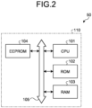
- the EEPROM 104 is a non-volatile memory capable of storing stored contents even after power is shut off, and stores control data and the like used by the CPU 101 to execute the control program. Various pieces of data stored in the EEPROM 104 are used on the control program loaded in the RAM 103 after the ECU 110 is powered on, and are overwritten in the EEPROM 104 at a predetermined timing.
- the EEPROM is used as the non-volatile memory, but the present invention is not limited thereto, and other non-volatile memories such as a FLASH-ROM (registered trademark) and an SDRAM may be used.
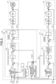
- Each control block in the reaction force control system 60 is realized by a reaction force control program executed in the ECU 110.
- each control block in the turning control system 70 is realized by a turning control program executed in the ECU 110. It is noted that some or all of the control blocks of the control device 50 may be realized by hardware. Additionally, the control device 50 may include the PWM control unit 37, the inverter 38, the motor current detector 39, the PWM control unit 47, the inverter 48, and the motor current detector 49.
- the current control unit 500 performs current control of the reaction force motor 31.
- the current control unit 500 calculates a voltage control command value Vh_ref such that a deviation Ih_err between the second reaction force motor current command value Ih_ref output from the steering torque control unit 400 and an actual current value (motor current value) Ih_act of the reaction force motor 31 detected by the motor current detector 39 approaches 0.
- driving of the turning motor 41 is controlled via the PWM control unit 47 and the inverter 48 based on the voltage control command value Vt ref.
- each of the steering torque control unit 400, the current control unit 500, the turning angle target value generation unit 600, the turning angle control unit 700, and the current control unit 800 only needs to have a configuration capable of realizing each control in the reaction force control system 60 or the turning control system 70, and is not limited by the configuration of each control block.
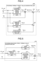
- a configuration of the steering torque target value generation unit 200 according to the present embodiment will be described with reference to FIG. 4 .
- FIG. 4 is a block diagram illustrating a configuration example of a steering torque target value generation unit according to the embodiment.
- the steering torque target value generation unit 200 includes a steering reaction force torque value generation unit 210, a road surface reaction force adaptive torque compensation value generation unit 220, a damping torque value generation unit 240, and a hysteresis compensation unit 250 as main components.
- FIG. 5 is a block diagram illustrating a configuration example of the steering reaction force torque value generation unit.
- a sign extraction unit 213 illustrated in FIG. 5 extracts a sign of the actual steering angle ⁇ h_act. Specifically, for example, a value of the actual steering angle ⁇ h_a is divided by an absolute value of the actual steering angle ⁇ h_a. Accordingly, the sign extraction unit 213 outputs "1" when the sign of the actual steering angle ⁇ h_act is "+", and outputs "-1" when the sign of the actual steering angle ⁇ h_act is "-”. Specifically, the sign extraction unit 213 generates, for example, a sign function Sgn( ⁇ h) of the actual steering angle ⁇ h_act.
- FIG. 6A is a diagram illustrating a characteristic example of a basic map.
- and a vehicle speed Vs subjected to absolute value processing in an absolute value calculation unit 212 are input to a steering reaction force torque map unit 211.
- the steering reaction force torque value generation unit 210 generates a torque value Tref_a0 with the vehicle speed Vs as a parameter using the basic map illustrated in FIG. 6A .
- a torque value Tref_a0 is used to generate basic steering reaction force according to the steering angle
- the torque value Tref_a0 has an angle-sensitive characteristic that increases and decreases depending on the steering angle
- the torque value Tref_a0 has a vehicle speed-sensitive characteristic that increases and decreases depending on the vehicle speed Vs. More specifically, as illustrated in FIG. 6A , the torque value Tref_a0 increases as the vehicle speed Vs increases. That is, the reaction force obtained by the torque value Tref_a0 derived by the basic map illustrated in FIG. 6A increases as the operation amount (the steering angle ⁇ h) of the steering wheel 1 by the driver increases, and increases as the speed (the vehicle speed Vs) of the vehicle increases. It is noted that the basic map illustrated in FIG. 6A has a vehicle speed-sensitive characteristic, but is not limited thereto.
- FIG. 6B is a diagram illustrating a characteristic example of a torque value Tref_a.
- the torque value Tref_a (a first torque value) illustrated in FIG. 6B is obtained by multiplying the torque value Tref_a0 output from the steering reaction force torque map unit 211 by the sign function Sgn( ⁇ h) output from the sign extraction unit 213 in a multiplication unit 293. It is noted that an aspect may be adopted in which the sign extraction unit 213 is not provided, and the torque value Tref_a (the first torque value) is obtained using a basic map corresponding to the positive and negative steering angles ⁇ h as illustrated in FIG. 6B .
- FIG. 7 is a block diagram illustrating a configuration example of the damping torque value generation unit.
- the damping torque value generation unit 240 includes a damping gain map unit 241, a differentiation unit 242, and a multiplication unit 243.
- FIG. 8A is a diagram illustrating a characteristic example of a damping gain map.
- the vehicle speed Vs is input to the damping gain map unit 241.
- the damping gain map unit 241 generates a damping gain DG using the damping gain map illustrated in FIG. 8A .
- the damping gain DG has a vehicle speed-sensitive characteristic that increases and decreases depending on the vehicle speed Vs.
- the damping torque value generation unit 240 multiplies an angular velocity (hereinafter, also referred to as a "steering angular velocity ⁇ h") of the steering wheel 1 calculated by differentiating the steering angle ⁇ h in the differentiation unit 242 by the damper gain DG output from the damping gain map unit 241 in the multiplication unit 243 and outputs a result value as a torque value Tref_b.
- FIG. 8B is a conceptual diagram illustrating a characteristic example of a torque value Tref_a + Tref_b.
- a solid line indicates the torque value Tref_a + Tref_b when the steering angular velocity ⁇ h is a positive value ( ⁇ h > 0)
- a broken line indicates the torque value Tref_a + Tref_b when the steering angular velocity ⁇ h is a negative value ( ⁇ h ⁇ 0).
- an alternate long and short dash line indicates the torque value Tref_a (the first torque value).
- the torque value Tref_a + Tref_b As illustrated in FIG. 8B , in the torque value Tref_a + Tref_b, the magnitude of the steering angle ⁇ h increases, and as the steering angle ⁇ h approaches a steering end restricted by the stopper (rotation restricting mechanism) 35, the increment of the torque rise with respect to a change in the steering angle ⁇ decreases.
- the torque value Tref_a + Tref_b has a characteristic that a change rate gradually decreases as the steering angle ⁇ h increases.
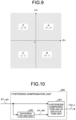
- FIG. 10 is a block diagram illustrating a configuration example of the hysteresis compensation unit.
- FIG. 11 is a diagram illustrating an example of an output characteristic of the hysteresis compensation unit.
- the horizontal axis represents the actual steering angle ⁇ h_act
- the vertical axis represents the torque compensation value Tref_c.
- a solid line indicates the torque compensation value Tref_c at the time of rightward steering
- a broken line indicates the torque compensation value Tref_c at the time of leftward steering.
- the torque compensation value Tref_c calculated by the hysteresis compensation value calculation unit 251 has hysteresis characteristics that differ between at the time of leftward turning and at the time of leftward turning.
- L1 represents a trajectory when rightward steering is performed from a center position (origin (0, 0)) of the steering wheel 1
- L2 represents a trajectory when switching from rightward steering to leftward steering occurs at coordinates A (x 1 , y 1 )
- L3 represents a trajectory when switching from rightward steering to leftward steering occurs at coordinates B (x 2 , y 2 ).
- the hysteresis compensation value calculation unit 251 calculates the torque compensation value Tref_c using the following formulas (1) and (2) based on the actual steering angle ⁇ h_act and the actual steering speed ⁇ h_act. Specifically, when the sign ⁇ h_act(sgn) of the actual steering speed ⁇ h_act is a positive value ("+"), the torque compensation value Tref_c is calculated using the following formula (1), and when the sign ⁇ h_act(sgn) of the actual steering speed ⁇ h_act is a negative value ("-”), the torque compensation value Tref_c is calculated using the following formula (2).
- x is the actual steering speed ⁇ h_act
- y R is the torque compensation value Tref_c at the time of rightward steering
- y L is the torque compensation value Tref_c at the time of leftward steering.
- a coefficient a is a value greater than 1
- a coefficient c is a value greater than 0.
- Ahys indicates an output width of the hysteresis characteristic (a width of the torque compensation value Tref_c)
- the coefficient c is a coefficient representing roundness of the hysteresis characteristic.
- the hysteresis compensation value calculation unit 251 takes over previous values of the actual steering angle ⁇ h_act and the torque compensation value Tref_c, and substitutes a coefficient b or b' shown in the following formula (3) or (4) into the formula (1) or (2) applied after the steering switching. This maintains continuity before and after steering switching.
- the hysteresis compensation value calculation unit 251 applies the previous value (coordinates A (x 1 , y 1 ) illustrated in FIG. 11 ) of the actual steering angle ⁇ h_act and the torque compensation value Tref_c to the formula (2), and substitutes the coefficient b' shown in the following formula (4) to calculate the torque compensation value Tref_c.
- the hysteresis compensation value calculation unit 251 applies the previous value (coordinate B (x 2 , y 2 ) illustrated in FIG. 11 ) of the actual steering angle ⁇ h_act and the torque compensation value Tref_c to the formula (1), and substitutes the coefficient b shown in the following formula (3) to calculate the torque compensation value Tref_c.
- b x 1 + 1 / c log a 1 ⁇ y 1 / Ahys
- b ′ x 1 ⁇ 1 / c log a 1 ⁇ y 1 / Ahys
- the formulas (3) and (4) can be derived by substituting x 1 for x and substituting y 1 for y R and y L in the formulas (1) and (2).
- the formulas (1), (2), (3), and (4) can be expressed by the following formulas (5), (6), (7), and (8), respectively.
- y R Ahys 1 ⁇ exp ⁇ c x ⁇ b
- y L ⁇ Ahys 1 ⁇ exp c x ⁇ b ′
- b x 1 + 1 / c log e 1 ⁇ y 1 / Ahys
- b ′ x 1 ⁇ 1 / c log e 1 ⁇ y 1 / Ahys
- the SBW system does not include an intermediate shaft that is mechanically coupled to the column axis 2. That is, the steering mechanism and the turning mechanism are mechanically separated from each other. For this reason, for example, it is necessary to transmit an oversteer state or an understeer state when a vehicle travels on a low ⁇ road where frictional resistance of the road surface is significantly reduced due to a frozen road surface, a hydroplaning phenomenon in rainy weather, or the like to the reaction force device 30 as steering reaction force.
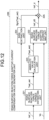
- FIG. 12 is a block diagram illustrating a configuration example of a road surface reaction force adaptive torque compensation value generation unit according to the first embodiment.
- the road surface reaction force adaptive torque compensation value generation unit 220 includes a road surface reaction force torque estimation unit 221 and a road surface reaction force adaptive torque map unit 222 as main components.
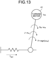
- FIG. 12 is an image diagram illustrating a state of torque generated between the road surface and the turning motor.
- the turning angle target value ⁇ t_ref is generated when a driver steers a steering wheel, and the turning motor 41 generates turning motor torque Tm for turning the turning wheels 5L and 5R according to the turning angle target value ⁇ t_ref.
- Tm turning motor torque
- the turning wheels 5L and 5R are turned, and road surface reaction force torque T SAT is generated.
- torque serving as resistance is generated by inertia (column-axis conversion inertia) J and friction (static friction) Fr acting on the column axis by (a rotor of) the turning motor 41, the deceleration mechanism, and the like.
- ⁇ M is a motor angular velocity converted into the column axis (converted into a value with respect to the column axis), and ⁇ M is a motor angular acceleration converted into the column axis.
- T SAT Tm ⁇ J ⁇ ⁇ M ⁇ Fr ⁇ sign ⁇ M ⁇ D M ⁇ ⁇ M
- the road surface reaction force torque T SAT can be calculated from the motor angular velocity ⁇ M , the motor angular acceleration ⁇ M , and the turning motor torque Tm.
- the column-axis conversion inertia J may be a value converted into a column axis simply using a relational formula between motor inertia and a reduction ratio.
- the first turning motor current command value Iref_a and the actual turning angle ⁇ t_act generated by the turning angle control unit 700 are input to the road surface reaction force torque estimation unit 221.
- the road surface reaction force torque estimation unit 221 calculates the road surface reaction force torque estimation value Tsat_est by replacing the road surface reaction force torque T SAT of the formula (10) with the road surface reaction force torque estimation value Tsat_est.
- FIG. 14 is a block diagram illustrating a configuration example of the road surface reaction force torque estimation unit.
- the road surface reaction force torque estimation unit 221 includes a conversion unit 311, an angular velocity calculation unit 312, an angular acceleration calculation unit 313, a block 314, a block 315, a block 316, a block 317, and subtraction units 318 and 319.
- the first turning motor current command value Iref_a is input to the conversion unit 311.
- the conversion unit 311 calculates the turning motor torque Tm converted to the column axis by multiplying a gear ratio and a torque constant that are determined in advance.
- the actual turning angle ⁇ t_act is input to the angular velocity calculation unit 312.
- the angular velocity calculation unit 312 converts the actual turning angle ⁇ t_act into the angle of the turning motor 41, performs differential calculation processing on the angle of the turning motor 41, and further calculates the motor angular velocity ⁇ M converted to the column axis by division by the gear ratio.
- the motor angular velocity ⁇ M is input the angular acceleration calculation unit 313.
- the angular acceleration calculation unit 313 differentiates the motor angular velocity ⁇ M and calculates the motor angular acceleration ⁇ M converted to the column axis.
- the road surface reaction force torque estimation value Tsat_est is calculated on the basis of the formula (10) with the configuration illustrated in FIG. 14 .
- the motor angular velocity ⁇ M output from the angular velocity calculation unit 312 is input to the block 314.
- the block 314 functions as a sign function and outputs a sign of input data.
- the motor angular velocity ⁇ M output from the angular velocity calculation unit 312 is input to the block 315.
- the block 315 multiplies the input data by the damper coefficient D M and outputs a result value.
- the block 316 multiplies the input data from the block 314 by the static friction Fr and outputs a result value.
- the motor angular acceleration ⁇ M output from the angular acceleration calculation unit 313 is input to the block 317.
- the block 317 multiplies the input data by the column-axis conversion inertia J and outputs the multiplied data.
- the subtraction unit 318 subtracts the output of the block 317 from the turning motor torque Tm output from the conversion unit 311.
- the subtraction unit 319 subtracts the output of the block 315 and the output of the block 316 from the output of the subtraction unit 318.
- the formula (10) can be realized. That is, the road surface reaction force torque estimation value Tsat_est is calculated by the configuration of the road surface reaction force torque estimation unit 221 illustrated in FIG. 14 .
- the angular velocity calculation unit 312 performs differential calculation processing on the detected angle of the turning motor 41, and further calculates the motor angular velocity ⁇ M converted into the column axis by division by the gear ratio.
- the column angle may be used as angle information instead of the actual turning angle ⁇ t_act or the angle of the turning motor 41. In this case, column axis conversion is unnecessary.
- the road surface reaction force torque estimation value Tsat_est may be calculated by a method other than the above-described method, or an estimation value corresponding to the road surface reaction force torque estimation value Tsat_est may be used.
- a calculation method of the road surface reaction force torque estimation value Tsat_est different from the above method will be described.
- the first turning motor current command value Iref_a generated by the turning angle control unit 700 is input to the road surface reaction force torque estimation unit 221.
- a transmission function Gfil expressed by the following formula (11) is set in the road surface reaction force torque estimation unit 221.
- the transmission function Gfil is stored in, for example, the ROM of the ECU constituting the control device 50.
- the transmission functions of the first order numerator and the second order denominator are assumed as the transmission function Gfil, but the order of the numerator denominator can be appropriately changed depending on an allowable amount of error between actual road surface reaction force torque Tsat_act and the road surface reaction force torque estimation value Tsat_est, the load of the ECU, and the like.
- the load on the ECU can be reduced.
- the transmission function Gfil calculates the road surface reaction force torque estimation value Tsat_est from the first turning motor current command value Iref_a by simulating the relationship between the first turning motor current command value Iref_a obtained by the experiment and the actual road surface reaction force torque Tsat_act.
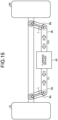
- FIG. 15 is a conceptual diagram illustrating a method of calculating the actual road surface reaction force torque acting on the turning mechanism.
- the actual road surface reaction force torque Tsat_act can be calculated by the following formula (13) using axial forces FL and FR applied to the tie rods 3a and 3b and a length L of each of the arms 6a and 6b determined for each vehicle type.
- Tsat_act FL ⁇ L ⁇ FR ⁇ L
- the actual road surface reaction force torque Tsat_act is calculated using the formula (13) using the axial forces FL and FR measured in advance by an experiment using an actual vehicle.
- the axial forces FL and FR can be measured, for example, by attaching force sensors to the tie rods 3a and 3b.
- FIG. 16 is a conceptual diagram illustrating a configuration for executing a simulation for deriving the transmission function Gfil.
- the first turning motor current command value Iref_a and the axial forces FL and FR are input to the processing device illustrated in FIG. 16 .
- the transmission function Gfil is derived such that the road surface reaction force torque estimation value Tsat_est expressed by the formula (12) approximates the actual road surface reaction force torque Tsat_act calculated by the formula (13).
- the processing device illustrated in FIG. 16 includes, for example, a frequency characteristic analysis device (a servo analyzer).
- the processing device executes curve fitting using a sweep method so as to derive the coefficients A, B, C, D, and E of the transmission function Gfil expressed by the formula (11).
- a curve fitting method for example, a least square approximation method can be used. It is note that the curve fitting method is not limited to the least squares approximation method.
- the road surface reaction force torque estimation unit 221 performs filter processing on the first turning motor current command value Iref_a generated by the turning angle control unit 700 using the transmission function Gfil derived as described above, and calculates the road surface reaction force torque estimation value Tsat_est expressed by the formula (12). As a result, the road surface reaction force torque estimation value Tsat_est corresponding to the behavior of the actual road surface reaction force torque Tsat_act when a vehicle actually travels is obtained.
- the transmission function used when the road surface reaction force torque estimation unit 221 calculates the road surface reaction force torque estimation value Tsat_est is not limited to the mode illustrated in the (11). Specifically, for example, the present disclosure is not limited by the order of the function N(s) or the function D(s).
- a sign extraction unit 224 extracts the sign of the road surface reaction force torque estimation value Tsat_est obtained by the above-described calculation method. Specifically, for example, the value of the road surface reaction force torque estimation value Tsat_est is divided by an absolute value of the road surface reaction force torque estimation value Tsat_est. Accordingly, the sign extraction unit 224 outputs "1" when the sign of the road surface reaction force torque estimation value Tsat_est is "+", and outputs "-1" when the sign of the road surface reaction force torque estimation value Tsat_est is "-”. Specifically, the sign extraction unit 224 generates, for example, a sign function Sgn(Tsat_est) of the road surface reaction force torque estimation value Tsat_est.
- FIG. 17 is a diagram illustrating a characteristic example of a road surface reaction force adaptive current map.
- and the vehicle speed Vs subjected to the absolute value processing in an absolute value calculation unit 223 are input to the road surface reaction force adaptive current map unit 222.
- the road surface reaction force adaptive current map unit 222 uses the road surface reaction force adaptive current map illustrated in FIG. 17 to generate a current compensation value Iref_d0 having the vehicle speed Vs as a parameter.
- the current compensation value Iref_d0 has a torque-sensitive characteristic that increases and decreases depending on the road surface reaction force torque estimation value
- the current compensation value Iref_d0 increases as the road surface reaction force torque estimation value
- the current compensation value Iref_d0 has a vehicle speed-sensitive characteristic that increases and decreases depending on the vehicle speed Vs. More specifically, the current compensation value Iref_d0 increases as the vehicle speed Vs increases as illustrated in FIG. 17 .
- the reaction force obtained by the current compensation value Iref_d0 derived by the road surface reaction force adaptive current map illustrated in FIG. 17 increases as the road surface reaction force torque estimation value
- the vehicle speed-sensitive characteristic is provided, but the present invention is not limited thereto.
- the road surface reaction force adaptive current compensation value generation unit 220 outputs the reaction force motor current compensation value Iref_d obtained by multiplying the current compensation value Iref_d0, which is an output value of the road surface reaction force adaptive current map unit 222, by the sign function Sgn(Tsat_est) of the road surface reaction force torque estimation value Tsat_est by a multiplication unit 225 and performing sign conversion.
- FIG. 18 is a diagram conceptually illustrating a characteristic example of the reaction force motor current compensation value after code conversion.
- the reaction force motor current compensation value Iref_d output from the road surface reaction force adaptive current compensation value generation unit 220 increases or decreases depending on the road surface reaction force torque estimation value Tsat_est which is an estimation value of the reaction force (self-aligning torque) acting from the road surface.
- Tsat_est is an estimation value of the reaction force (self-aligning torque) acting from the road surface.
- the characteristics of the road surface reaction force adaptive current map are not limited to the above-described mode illustrated in FIG. 17 or 18 . Furthermore, for example, instead of the mode of the map illustrated in FIG. 17 or 18 , a mode in which a characteristic is defined by a predetermined transmission function may be used.
- the road surface reaction force torque estimation value Tsat_est changes depending on the state of the vehicle, such as the vehicle speed and the steering angle, in addition to the situation of the road surface. For this reason, depending on the state of the vehicle, the situation of the road surface cannot be sufficiently reflected, and a steering feeling depending on the situation of the road surface or the state of the vehicle may not be obtained.
- FIG. 19A is a diagram conceptually illustrating a first example of a gain ratio setting example in the gain ratio generation unit according to the first embodiment.
- FIG. 19B is a diagram conceptually illustrating a second example of the gain ratio setting example in the gain ratio generation unit according to the first embodiment.
- FIG. 19C is a diagram conceptually illustrating a third example of the gain ratio setting example in the gain ratio generation unit according to the first embodiment.
- a first gain Ga and a second gain Gb are generated with the vehicle speed Vs as a parameter.
- the vehicle speed Vs is input to the gain ratio generation unit 230 of the steering torque target value generation unit 200 according to the first embodiment.
- the gain ratio generation unit 230 generates the first gain Ga that increases or decreases depending on the vehicle speed Vs and the second gain Gb in which the sum of the first gain Ga and the second gain Gb is 1.
- the first gain Ga is multiplied by the torque value Tref_a (the first torque value) by a multiplication unit 261 in the steering torque target value generation unit 200.
- the second gain Gb is multiplied by the reaction force motor current compensation value Iref_d by a multiplication unit 262.
- the gain ratio generation unit 230 monotonically reduces the first gain Ga to be multiplied by the torque value Tref_a (the first torque value) within the range from a first vehicle speed Vs_A or higher to a second vehicle speed Vs_B or lower. Accordingly, the second gain Gb by which the reaction force motor current compensation value Iref_d is multiplied monotonically increases within the range from the first vehicle speed Vs_A or higher to the second vehicle speed Vs_B or lower.
- the first vehicle speed Vs_A is, for example, 5 [km/h].
- the second vehicle speed Vs_B is, for example, 30 [km/h].
- the present disclosure is not limited by the respective values of the first vehicle speed Vs_A and the second vehicle speed Vs_B.
- FIG. 19A illustrates an example in which the maximum value Ga_max of the first gain Ga in the range of the first vehicle speed Vs_A or lower is larger than the maximum value Gb_max of the second gain Gb in the range of the second vehicle speed Vs_B or higher.
- the minimum value Gb_min of the second gain Gb in the range of the first vehicle speed Vs_A or lower is larger than the minimum value Ga_min of the first gain Ga in the range of the second vehicle speed Vs_B or higher.
- FIG. 19B illustrates an example in which the maximum value Ga_max of the first gain Ga in the range of the first vehicle speed Vs_A or lower is smaller than the maximum value Gb_max of the second gain Gb in the range of the second vehicle speed Vs_B or higher.
- the minimum value Gb_min of the second gain Gb in the range of the first vehicle speed Vs_A or lower is smaller than the minimum value Ga_min of the first gain Ga in the range of the second vehicle speed Vs_B or higher.
- FIG. 19C illustrates an example in which the maximum value Ga_max of the first gain Ga in the range of the first vehicle speed Vs_A or lower is equal to the maximum value Gb_max of the second gain Gb in the range of the second vehicle speed Vs_B or higher.
- the minimum value Gb_min of the second gain Gb in the range of the first vehicle speed Vs_A or lower is equal to the minimum value Ga_min of the first gain Ga in the range of the second vehicle speed Vs_B or higher.
- Each value and magnitude relationship of the maximum value Ga_max of the first gain Ga, the minimum value Ga_min of the first gain Ga, the maximum value Gb_max of the second gain Gb, and the minimum value Gb_min of the second gain Gb may be appropriately set according to the motion performance of the vehicle on which the control device 50 according to the present disclosure is mounted, vehicle specifications, and the like.
- the steering torque target value generation unit 200 adds (addition units 271, 272, and 273) a torque value Ga ⁇ Tref_a obtained by multiplying the torque value Tref_a (the first torque value) output from the steering reaction force torque value generation unit 210 by the first gain Ga (the multiplication unit 261), the torque value Tref_b output from the damping torque value generation unit 240, and the torque compensation value Tref_c output from the hysteresis compensation unit 250, and outputs a result value as the steering torque target value Th_ref.
- the steering torque control unit 400 adds a current compensation value Gb ⁇ Iref_d obtained by multiplying the reaction force motor current compensation value Iref_d output from the road surface reaction force adaptive current compensation value generation unit 220 by the second gain Gb (the multiplication unit 262) to the first reaction force motor current command value Ih_ref0, and outputs the first reaction force motor current command value Ih_ref0 as the second reaction force motor current command value Ih_ref in which upper and lower limit values of the first reaction force motor current command value Ih_ref0 are limited by the output limitation unit.
- steering reaction force corresponding to the road surface reaction force torque estimation value Tsat_est can be applied to the steering wheel 1 at a ratio corresponding to the vehicle speed Vs.
- the steering torque target value generation unit 200 generates the steering torque target value Th_ref by multiplying the torque value Tref_a (the first torque value) output from the steering reaction force torque value generation unit 210 by a relatively large first gain Ga in a region where the vehicle speed Vs is relatively small, and generates the second reaction force motor current command value Ih_ref by multiplying the reaction force motor current compensation value Iref_d output from the road surface reaction force adaptive current compensation value generation unit 220 by a relatively large second gain Gb in a region where the vehicle speed Vs is relatively large.
- a component of reaction force torque due to elastic deformation of a tire is a main component of the road surface reaction force torque, and a proportion of the reaction torque component due to the road surface state to the road surface reaction force torque is small. That is, when the output of the road surface reaction force-sensitive torque generation unit 220 relatively increases in the low speed region, although it is difficult to obtain the road surface state, heavy steering torque is applied, so that the driver's steering feeling deteriorates. Therefore, in the low speed region where the vehicle speed Vs is relatively small, the steering feeling reflecting the situation of the road surface and the vehicle speed Vs can be obtained by using the relatively large first gain Ga and the relatively small second gain Gb.
- the gain ratio setting example in the gain ratio generation unit 230 according to the first embodiment is an example, and is not limited to the modes illustrated in FIGS. 19A, 19B , and 19C described above.
- the first gain Ga to be multiplied by the torque value Tref_a may gradually decrease as the vehicle speed Vs increases, and accordingly, the second gain Gb to be multiplied by the reaction force motor current compensation value Iref_d may gradually increase as the vehicle speed Vs increases.
- the first gain Ga to be multiplied by the torque value Tref_a may gradually increase as the vehicle speed Vs decreases
- the second gain Gb to be multiplied by the reaction force motor current compensation value Iref_d may gradually decrease as the vehicle speed Vs decreases.
- FIG. 20 is a diagram illustrating an example of a control block configuration of a control device according to the second embodiment.
- FIG. 21 is a diagram conceptually illustrating an example of a gain ratio setting example in a gain ratio generation unit according to the second embodiment.
- the first gain Ga and the second gain Gb are generated using the actual steering angle ⁇ h_act as a parameter.
- the actual steering angle ⁇ h_act is input to a gain ratio generation unit 230a of a steering torque target value generation unit 200a according to the second embodiment.
- the gain ratio generation unit 230a generates the first gain Ga that increases or decreases depending on the actual steering angle ⁇ h_act and the second gain Gb in which the sum of the first gain Ga and the second gain Gb is 1.
- the first gain Ga is multiplied by the torque value Tref_a (the first torque value) by the multiplication unit 261.
- the second gain Gb is multiplied by the reaction force motor current compensation value Iref_d by the multiplication unit 262.
- the gain ratio generation unit 230a monotonically reduces the first gain Ga to be multiplied by the torque value Tref_a (the first torque value) within the range from a first steering angle ⁇ h_A or more to a second steering angle ⁇ h_B or less. Accordingly, the second gain Gb to be multiplied by the reaction force motor current compensation value Iref_d monotonically increases within the range from the first steering angle ⁇ h_A or more to the second steering angle ⁇ h_B or less.
- the first steering angle ⁇ h_A is, for example, 3 [deg].
- the second steering angle ⁇ h_B is, for example, 20 [deg].
- the present disclosure is not limited by the respective values of the first steering angle ⁇ h_A and the second steering angle ⁇ h_B.
- FIG. 21 illustrates an example in which the maximum value Ga_max of the first gain Ga in the range of the first steering angle ⁇ h_A or less is larger than the maximum value Gb_max of the second gain Gb in the range of the second steering angle ⁇ h_B or more.
- the minimum value Gb_min of the second gain Gb in the range of the first steering angle ⁇ h_A or less is larger than the minimum value Ga_min of the first gain Ga in the range of the second steering angle ⁇ h_B or more.
- the maximum value Ga_max of the first gain Ga in the range of the first steering angle ⁇ h_A or less may be smaller than the maximum value Gb_max of the second gain Gb in the range of the second steering angle ⁇ h_B or more
- the minimum value Gb_min of the second gain Gb in the range of the first steering angle ⁇ h_A or less may be smaller than the minimum value Ga_min of the first gain Ga in the range of the second steering angle ⁇ h_B or more.
- the maximum value Ga_max of the first gain Ga in the range of the first steering angle ⁇ h_A or less may be equal to the maximum value Gb_max of the second gain Gb in the range of the second steering angle ⁇ h_B or more
- the minimum value Gb_min of the second gain Gb in the range of the first steering angle ⁇ h_A or less may be equal to the minimum value Ga_min of the first gain Ga in the range of the second steering angle ⁇ h_B or more.
- Each value and magnitude relationship of the maximum value Ga_max of the first gain Ga, the minimum value Ga_min of the first gain Ga, the maximum value Gb_max of the second gain Gb, and the minimum value Gb_min of the second gain Gb may be appropriately set according to the motion performance of the vehicle on which the control device 50 according to the present disclosure is mounted, vehicle specifications, and the like.
- the steering torque target value generation unit 200a adds (addition units 271, 272, and 273) the torque value Ga ⁇ Tref_a obtained by multiplying the torque value Tref_a (the first torque value) output from the steering reaction force torque value generation unit 210 by the first gain Ga (the multiplication unit 261), the torque value Tref_b output from the damping torque value generation unit 240, and the torque compensation value Tref_c output from the hysteresis compensation unit 250, and outputs a result value as the steering torque target value Th_ref.
- the steering torque control unit 400 adds a current compensation value Gb ⁇ Iref_d obtained by multiplying the reaction force motor current compensation value Iref_d output from the road surface reaction force adaptive current compensation value generation unit 220 by the second gain Gb (the multiplication unit 262) to the first reaction force motor current command value Ih_ref0, and outputs the first reaction force motor current command value Ih_ref0 as the second reaction force motor current command value Ih_ref in which upper and lower limit values of the first reaction force motor current command value Ih_ref0 are limited by the output limitation unit.
- steering reaction force corresponding to the road surface reaction force torque estimation value Tsat_est can be applied to the steering wheel 1 at a ratio corresponding to the actual steering angle ⁇ h_act.
- the steering torque target value generation unit 200a generates the steering torque target value Th_ref by multiplying the torque value Tref_a (the first torque value) output from the steering reaction force torque value generation unit 210 by a relatively large first gain Ga in a region where the actual steering angle ⁇ h_act is relatively small, and generates the steering torque target value Th_ref by multiplying the reaction force motor current compensation value Iref_d output from the road surface reaction force adaptive current compensation value generation unit 220 by a relatively large second gain Gb in a region where the actual steering angle ⁇ h_act is relatively large.
- the steering torque target value generation unit 200a generates the steering torque target value Th_ref by multiplying the reaction force motor current compensation value Iref_d output from the road surface reaction force adaptive current compensation value generation unit 220 by a relatively large second gain Gb in a region
- the gain ratio setting example in the gain ratio generation unit 230a according to the second embodiment is an example, and is not limited to the mode illustrated in FIG. 21 described above.
- the first gain Ga to be multiplied by the torque value Tref_a (the first torque value) may gradually decrease as the actual steering angle ⁇ h_act increases
- the second gain Gb to be multiplied by the reaction force motor current compensation value Iref_d may gradually increase as the actual steering angle ⁇ h_act increases.
- the first gain Ga to be multiplied by the torque value Tref_a may gradually increase as the actual steering angle ⁇ h_act decreases, and accordingly, the second gain Gb to be multiplied by the reaction force motor current compensation value Iref_d may gradually decrease as the actual steering angle ⁇ h_act decreases.
- FIG. 22 is a diagram illustrating an example of a control block configuration of a control device according to the third embodiment.
- FIG. 23 is a diagram conceptually illustrating an example of a gain ratio setting example in a gain ratio generation unit according to the third embodiment.
- the first gain Ga and the second gain Gb are generated using the actual turning angle ⁇ t_act as a parameter.
- the actual turning angle ⁇ t_act is input to a gain ratio generation unit 230b of a steering torque target value generation unit 200b according to the third embodiment.
- the gain ratio generation unit 230b generates the first gain Ga that increases or decreases depending on the actual turning angle ⁇ t_act and the second gain Gb in which the sum of the first gain Ga and the second gain Gb is 1.
- the first gain Ga is multiplied by the torque value Tref_a (the first torque value) by the multiplication unit 261 in the steering torque target value generation unit 200.
- the second gain Gb is multiplied by the reaction force motor current compensation value Iref_d by the multiplication unit 262.
- the gain ratio generation unit 230b monotonically reduces the first gain Ga to be multiplied by the torque value Tref_a (the first torque value) within the range from a first turning angle ⁇ t_A or more to a second turning angle ⁇ t_B or less. Accordingly, the second gain Gb to be multiplied by the reaction force motor current compensation value Iref_d monotonically increases within the range from the first turning angle ⁇ t_A or more to the second turning angle ⁇ t_B or less.
- the first turning angle ⁇ t_A is, for example, 3 [deg].
- the second turning angle ⁇ t_B is, for example, 20 [deg].
- the present disclosure is not limited by the respective values of the first turning angle ⁇ t_A and the second turning angle ⁇ t_B.
- FIG. 23 illustrates an example in which the maximum value Ga_max of the first gain Ga in the range of the first turning angle ⁇ t_A or less is larger than the maximum value Gb_max of the second gain Gb in the range of the second turning angle ⁇ t_B or more.
- the minimum value Gb_min of the second gain Gb in the range of the first turning angle ⁇ t_A or less is larger than the minimum value Ga_min of the first gain Ga in the range of the second turning angle ⁇ t_B or more.
- the maximum value Ga_max of the first gain Ga in the range of the first turning angle ⁇ t_A or less may be smaller than the maximum value Gb_max of the second gain Gb in the range of the second turning angle ⁇ t_B or more
- the minimum value Gb_min of the second gain Gb in the range of the first turning angle ⁇ t_A or less may be smaller than the minimum value Ga_min of the first gain Ga in the range of the second turning angle ⁇ t_B or more.
- the maximum value Ga_max of the first gain Ga in the range of the first turning angle ⁇ t_A or less may be equal to the maximum value Gb_max of the second gain Gb in the range of the second turning angle ⁇ t_B or more
- the minimum value Gb_min of the second gain Gb in the range of the first turning angle ⁇ t_A or less may be equal to the minimum value Ga_min of the first gain Ga in the range of the second turning angle ⁇ t_B or more.
- Each value and magnitude relationship of the maximum value Ga_max of the first gain Ga, the minimum value Ga_min of the first gain Ga, the maximum value Gb_max of the second gain Gb, and the minimum value Gb_min of the second gain Gb may be appropriately set according to the motion performance of the vehicle on which the control device 50 according to the present disclosure is mounted, vehicle specifications, and the like.
- steering reaction force corresponding to the road surface reaction force torque estimation value Tsat_est can be applied to the steering wheel 1 at a ratio corresponding to the actual turning angle ⁇ t_act.
- the steering torque target value generation unit 200b generates the steering torque target value Th_ref by multiplying the torque value Tref_a (the first torque value) output from the steering reaction force torque value generation unit 210 by a relatively large first gain Ga in a region where the actual turning angle ⁇ t_act is relatively small, and generates the second reaction force motor current command value Ih_ref by multiplying the reaction force motor current compensation value Iref_d output from the road surface reaction force adaptive current compensation value generation unit 220 by a relatively large second gain Gb in a region where the actual turning angle ⁇ t_act is relatively large.
- the steering torque target value generation unit 200b generates the steering torque target value Th_ref by multiplying the torque value Tref_a (the first torque value) output from the steering reaction force torque value generation unit 210 by a relatively large first gain Ga in a
- the gain ratio setting example in the gain ratio generation unit 230b according to the third embodiment is an example, and is not limited to the mode illustrated in FIG. 23 described above.
- the first gain Ga to be multiplied by the torque value Tref_a (the first torque value) may gradually decrease as the actual turning angle ⁇ t_act increases
- the second gain Gb to be multiplied by the reaction force motor current compensation value Iref_d may gradually increase as the actual turning angle ⁇ t_act increases.
- the first gain Ga to be multiplied by the torque value Tref_a may gradually increase as the actual turning angle ⁇ t_act increases, and accordingly, the second gain Gb to be multiplied by the reaction force motor current compensation value Iref_d may gradually decrease as the actual turning angle ⁇ t_act decreases.
- FIG. 24 is a diagram illustrating an example of a control block configuration of a control device according to the fourth embodiment.
- FIG. 25 is a block diagram illustrating a configuration example of a gain ratio generation unit according to the fourth embodiment.
- FIGS. 26A and 26B are diagrams each conceptually illustrating an example of a gain ratio setting example in the gain ratio generation unit according to the fourth embodiment.
- the first gain Ga and the second gain Gb are generated using the vehicle speed Vs and the actual steering angle ⁇ h_act as parameters.
- the vehicle speed Vs and the actual steering angle ⁇ h_act are input to a gain ratio generation unit 230c of a steering torque target value generation unit 200c according to the fourth embodiment.
- the gain ratio generation unit 230c includes a first gain ratio generation unit 230, a second gain ratio generation unit 230a, and a gain ratio calculation unit 231.
- the first gain ratio generation unit 230 of the gain ratio generation unit 230c is substantially the same component as the gain ratio generation unit 230 according to the first embodiment.
- the gain ratio generation unit 230 generates a first gain Ga1 that increases or decreases depending on the vehicle speed Vs and a second gain Gb1 in which the sum of the first gain Ga1 and the second gain Gb1 is 1.
- the first gain ratio generation unit 230 monotonically reduces the first gain Ga1 within the range from the first vehicle speed Vs_A or higher to the second vehicle speed Vs_B or less. Accordingly, the second gain Gb1 monotonically increases within the range from the first vehicle speed Vs_A or higher to the second vehicle speed Vs_B or less.
- the first vehicle speed Vs_A is, for example, 5 [km/h].
- the second vehicle speed Vs_B is, for example, 30 [km/h].
- the present disclosure is not limited by the respective values of the first vehicle speed Vs_A and the second vehicle speed Vs_B.
- FIG. 26A illustrates an example in which the maximum value Ga1_max of the first gain Ga1 in the range of the first vehicle speed Vs_A or lower is larger than the maximum value Gb1_max of the second gain Gb1 in the range of the second vehicle speed Vs_B or higher.
- the minimum value Gb1_min of the second gain Gb1 in the range of the first vehicle speed Vs_A or lower is larger than the minimum value Ga1_min of the first gain Ga1 in the range of the second vehicle speed Vs_B or higher.
- the maximum value Ga1_max of the first gain Ga1 in the range of the first vehicle speed Vs_A or lower may be smaller than the maximum value Gb1_max of the second gain Gb1 in the range of the second vehicle speed Vs_B or higher
- the minimum value Gb1_min of the second gain Gb1 in the range of the first vehicle speed Vs_A or lower may be smaller than the minimum value Ga1_min of the first gain Ga1 in the range of the second vehicle speed Vs_B or higher.
- the maximum value Ga1_max of the first gain Ga1 in the range of the first vehicle speed Vs_A or lower may be equal to the maximum value Gb1_max of the second gain Gb1 in the range of the second vehicle speed Vs_B or higher
- the minimum value Gb1_min of the second gain Gb1 in the range of the first vehicle speed Vs_A or lower may be equal to the minimum value Ga1_min of the first gain Ga1 in the range of the second vehicle speed Vs_B or higher.
- Each value and magnitude relationship of the maximum value Ga_max of the first gain Ga, the minimum value Ga_min of the first gain Ga, the maximum value Gb_max of the second gain Gb, and the minimum value Gb_min of the second gain Gb may be appropriately set according to the motion performance of the vehicle on which the control device 50 according to the present disclosure is mounted, vehicle specifications, and the like.
- the second gain ratio generation unit 230a of the gain ratio generation unit 230c is substantially the same component as the gain ratio generation unit 230a according to the second embodiment.
- the second gain ratio generation unit 230a generates a first gain Ga2 that increases or decreases depending on the actual turning angle ⁇ t_act and a second gain Gb2 in which the sum of the first gain Ga2 and the second gain Gb2 is 1.
- the second gain ratio generation unit 230a monotonically reduces the first gain Ga2 within the range from the first steering angle ⁇ h_A or more to the second steering angle ⁇ h_B or less. Accordingly, the second gain Gb2 monotonically increases within the range from the first steering angle ⁇ h_A or more to the second steering angle ⁇ h_B or less.
- the first steering angle ⁇ h_A is, for example, 3 [deg].
- the second steering angle ⁇ h_B is, for example, 20 [deg].
- the present disclosure is not limited by the respective values of the first steering angle ⁇ h_A and the second steering angle ⁇ h_B.
- FIG. 26B illustrates an example in which the maximum value Ga2_max of the first gain Ga2 in the range of the first steering angle ⁇ h_A or less is larger than the maximum value Gb2_max of the second gain Gb2 in the range of the second steering angle ⁇ h_B or more.
- the minimum value Gb2_min of the second gain Gb2 in the range of the first steering angle ⁇ h_A or less is larger than the minimum value Ga2_min of the first gain Ga2 in the range of the second steering angle ⁇ h_B or more.
- the maximum value Ga2_max of the first gain Ga2 in the range of the first steering angle ⁇ h_A or less may be smaller than the maximum value Gb2_max of the second gain Gb2 in the range of the second steering angle ⁇ h_B or more
- the minimum value Gb2_min of the second gain Gb2 in the range of the first steering angle ⁇ h_A or less may be smaller than the minimum value Ga2_min of the first gain Ga2 in the range of the second steering angle ⁇ h_B or more.
- the maximum value Ga2_max of the first gain Ga2 in the range of the first steering angle ⁇ h_A or less may be equal to the maximum value Gb2_max of the second gain Gb2 in the range of the second steering angle ⁇ h_B or more
- the minimum value Gb2_min of the second gain Gb2 in the range of the first steering angle ⁇ h_A or less may be equal to the minimum value Ga2_min of the first gain Ga2 in the range of the second steering angle ⁇ h_B or more.
- the gain ratio calculation unit 231 receives the first gain Ga1 and the second gain Gb1 output from the first gain ratio generation unit 230, and the first gain Ga2 and the second gain Gb2 output from the second gain ratio generation unit 230a.
- the gain ratio calculation unit 231 calculates the first gain Ga by using the following formula (14) and calculates the second gain Gb by using the following formula (15).
- Ga Ga 1 ⁇ Ga 2 / Ga 1 ⁇ Ga 2 + Gb 1 ⁇ Gb 2
- Gb Gb 1 ⁇ Gb 2 / Ga 1 ⁇ Ga 2 + Gb 1 ⁇ Gb 2
- the first gain Ga is multiplied by the torque value Tref_a (the first torque value) by the multiplication unit 261.
- the second gain Gb is multiplied by the reaction force motor current compensation value Iref_d by the multiplication unit 262.
- the steering torque target value generation unit 200c adds (addition units 271, 272, and 273) the torque value Ga ⁇ Tref_a obtained by multiplying the torque value Tref_a (the first torque value) output from the steering reaction force torque value generation unit 210 by the first gain Ga (the multiplication unit 261), the torque value Tref_b output from the damping torque value generation unit 240, and the torque compensation value Tref_c output from the hysteresis compensation unit 250, and outputs a result value as the steering torque target value Th_ref.
- the steering torque control unit 400 adds a current compensation value Gb ⁇ Iref_d obtained by multiplying the reaction force motor current compensation value Iref_d output from the road surface reaction force adaptive current compensation value generation unit 220 by the second gain Gb (the multiplication unit 262) to the first reaction force motor current command value Ih_ref0, and outputs the first reaction force motor current command value Ih_ref0 as the second reaction force motor current command value Ih_ref in which upper and lower limit values of the first reaction force motor current command value Ih_ref0 are limited by the output limitation unit.
- steering reaction force corresponding to the road surface reaction force torque estimation value Tsat_est can be applied to the steering wheel 1 at a ratio corresponding to both the vehicle speed Vs and the actual steering angle ⁇ h_act.
- the steering torque target value generation unit 200c generates the steering torque target value Th_ref by multiplying the torque value Tref_a (the first torque value) output from the steering reaction force torque value generation unit 210 by a relatively large first gain Ga in a region where the vehicle speed Vs or the actual steering angle ⁇ h_act is relatively small, and generates the second reaction force motor current command value Ih_ref by multiplying the reaction force motor current compensation value Iref_d output from the road surface reaction force adaptive current compensation value generation unit 220 by a relatively large second gain Gb in a region where the vehicle speed Vs or the actual steering angle ⁇ h_act is relatively large.
- the steering torque target value generation unit 200c generates the steering torque target value Th_ref by multiplying the torque value Tref_a (the first torque value) output from the steering
- the gain ratio setting example in the first gain ratio generation unit 230 according to the fourth embodiment is an example, and is not limited to the mode illustrated in FIG. 26A described above.
- the first gain Ga1 may gradually decrease as the vehicle speed Vs increases, and accordingly, the second gain Gb1 may gradually increase as the vehicle speed Vs increases.
- the first gain Ga1 may gradually increase as the vehicle speed Vs decreases, and accordingly, the second gain Gb1 may gradually decrease as the vehicle speed Vs decreases.
- the gain ratio setting example in the second gain ratio generation unit 230a according to the fourth embodiment is an example, and is not limited to the mode illustrated in FIG. 26B described above.
- the first gain Ga2 may gradually decrease as the actual steering angle ⁇ h_act increases, and accordingly, the second gain Gb2 may gradually increase as the actual steering angle ⁇ h_act increases.
- the first gain Ga2 may gradually increase as the actual steering angle ⁇ h_act decreases, and accordingly, the second gain Gb2 may gradually decrease as the actual steering angle ⁇ h_act decreases.
- FIG. 27 is a diagram illustrating an example of a control block configuration of a control device according to the fifth embodiment.
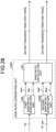
- FIG. 28 is a block diagram illustrating a configuration example of a gain ratio generation unit according to the fifth embodiment.
- FIGS. 29A and 29B are diagrams each conceptually illustrating an example of a gain ratio setting example in the gain ratio generation unit according to the fifth embodiment.
- the first gain Ga and the second gain Gb are generated using the vehicle speed Vs and the actual turning angle ⁇ t_act as parameters.
- the vehicle speed Vs and the actual turning angle ⁇ t_act are input to a gain ratio generation unit 230d of a steering torque target value generation unit 200d according to the fifth embodiment.
- the gain ratio generation unit 230d includes a first gain ratio generation unit 230, a second gain ratio generation unit 230b, and a gain ratio calculation unit 231.
- the first gain ratio generation unit 230 of the gain ratio generation unit 230d is substantially the same component as the gain ratio generation unit 230 according to the first embodiment.
- the gain ratio generation unit 230 generates a first gain Ga1 that increases or decreases depending on the vehicle speed Vs and a second gain Gb1 in which the sum of the first gain Ga1 and the second gain Gb1 is 1.
- FIG. 29A illustrates an example in which the maximum value Ga1_max of the first gain Ga1 in the range of the first vehicle speed Vs_A or lower is larger than the maximum value Gb1_max of the second gain Gb1 in the range of the second vehicle speed Vs_B or higher.
- the minimum value Gb1_min of the second gain Gb1 in the range of the first vehicle speed Vs_A or lower is larger than the minimum value Ga1_min of the first gain Ga1 in the range of the second vehicle speed Vs_B or higher.
- the maximum value Ga1_max of the first gain Ga1 in the range of the first vehicle speed Vs_A or lower may be smaller than the maximum value Gb1_max of the second gain Gb1 in the range of the second vehicle speed Vs_B or higher
- the minimum value Gb1_min of the second gain Gb1 in the range of the first vehicle speed Vs_A or lower may be smaller than the minimum value Ga1_min of the first gain Ga1 in the range of the second vehicle speed Vs_B or higher.
- Each value and magnitude relationship of the maximum value Ga_max of the first gain Ga, the minimum value Ga_min of the first gain Ga, the maximum value Gb_max of the second gain Gb, and the minimum value Gb_min of the second gain Gb may be appropriately set according to the motion performance of the vehicle on which the control device 50 according to the present disclosure is mounted, vehicle specifications, and the like.
- the second gain ratio generation unit 230b monotonically reduces the first gain Ga2 within the range from the first turning angle ⁇ t_A or more to the second turning angle ⁇ t_B or less. Accordingly, the second gain Gb2 monotonically increases within the range from the first turning angle ⁇ t_A or more to the second turning angle ⁇ t_B or less.
- the first turning angle ⁇ t_A is, for example, 3 [deg].
- the second turning angle ⁇ t_B is, for example, 20 [deg].
- the present disclosure is not limited by the respective values of the first turning angle ⁇ t_A and the second turning angle ⁇ t_B.
- FIG. 29B illustrates an example in which the maximum value Ga2_max of the first gain Ga2 in the range of the first turning angle ⁇ t_A or less is larger than the maximum value Gb2_max of the second gain Gb2 in the range of the second turning angle ⁇ t_B or more.
- the minimum value Gb2_min of the second gain Gb2 in the range of the first turning angle ⁇ t_A or less is larger than the minimum value Ga2_min of the first gain Ga2 in the range of the second turning angle ⁇ t_B or more.
- the maximum value Ga2_max of the first gain Ga2 in the range of the first turning angle ⁇ t_A or less may be smaller than the maximum value Gb2_max of the second gain Gb2 in the range of the second turning angle ⁇ t_B or more
- the minimum value Gb2_min of the second gain Gb2 in the range of the first turning angle ⁇ t_A or less may be smaller than the minimum value Ga2_min of the first gain Ga2 in the range of the second turning angle ⁇ t_B or more.
- the maximum value Ga2_max of the first gain Ga2 in the range of the first turning angle ⁇ t_A or less may be equal to the maximum value Gb2_max of the second gain Gb2 in the range of the second turning angle ⁇ t_B or more
- the minimum value Gb2_min of the second gain Gb2 in the range of the first turning angle ⁇ t_A or less may be equal to the minimum value Ga2_min of the first gain Ga2 in the range of the second turning angle ⁇ t_B or more.
- the gain ratio calculation unit 231 calculates the first gain Ga and the second gain Gb using the formulas (14) and (15) described in the fourth embodiment.
- the steering torque control unit 400 adds a current compensation value Gb ⁇ Iref_d obtained by multiplying the reaction force motor current compensation value Iref_d output from the road surface reaction force adaptive current compensation value generation unit 220 by the second gain Gb (the multiplication unit 262) to the first reaction force motor current command value Ih_ref0, and outputs the first reaction force motor current command value Ih_ref0 as the second reaction force motor current command value Ih_ref in which upper and lower limit values of the first reaction force motor current command value Ih_ref0 are limited by the output limitation unit.
- steering reaction force corresponding to the road surface reaction force torque estimation value Tsat_est can be applied to the steering wheel 1 at a ratio corresponding to both the vehicle speed Vs and the actual turning angle ⁇ t_act.
- the steering torque target value generation unit 200d generates the steering torque target value Th_ref by multiplying the torque value Tref_a (the first torque value) output from the steering reaction force torque value generation unit 210 by a relatively large first gain Ga in a region where the vehicle speed Vs or the actual turning angle ⁇ t_act is relatively small, and generates the second reaction force motor current command value Ih_ref by multiplying the reaction force motor current compensation value Iref_d output from the road surface reaction force adaptive current compensation value generation unit 220 by a relatively large second gain Gb in a region where the vehicle speed Vs or the actual turning angle ⁇ t_act is relatively large.
- the steering torque target value generation unit 200d generates the steering torque target value Th_ref by multiplying the torque value Tref_a (the first torque value) output from the steering
- the gain ratio setting example in the first gain ratio generation unit 230 according to the fifth embodiment is an example, and is not limited to the mode illustrated in FIG. 29A described above.
- the first gain Ga1 may gradually decrease as the vehicle speed Vs increases, and accordingly, the second gain Gb1 may gradually increase as the vehicle speed Vs increases.
- the first gain Ga1 may gradually increase as the vehicle speed Vs decreases, and accordingly, the second gain Gb1 may gradually decrease as the vehicle speed Vs decreases.
- the gain ratio setting example in the second gain ratio generation unit 230b according to the fifth embodiment is an example, and is not limited to the mode illustrated in FIG. 29B described above.
- the first gain Ga2 may gradually decrease as the actual turning angle ⁇ t_act increases, and accordingly, the second gain Gb2 may gradually increase as the actual turning angle ⁇ t_act increases.
- the first gain Ga2 may gradually increase as the actual turning angle ⁇ t_act decreases, and accordingly, the second gain Gb2 may gradually increase as the actual turning angle ⁇ t_act decreases.
- a gain ratio generation unit 230e of a steering torque target value generation unit 200e has a gain ratio setting map illustrated in FIG. 31 .
- the gain ratio generation unit 230e generates the second gain Gb having the vehicle speed Vs and the actual steering angle ⁇ h_act as parameters using the gain ratio map illustrated in FIG. 31 .
- the gain ratio generation unit 230e generates the second gain Gb using the gain ratio map illustrated in FIG. 31 and calculates the first gain Ga using the formula (16).
- the gain ratio generation unit 230e may have a gain ratio map for generating the first gain Ga using the vehicle speed Vs and the actual steering angle ⁇ h_act as parameters, and may calculate the second gain Gb using the following formula (17) obtained by modifying the formula (16).
- Gb 1 ⁇ Ga
- the first gain Ga and the second gain Gb are generated using the vehicle speed Vs and the actual steering angle ⁇ h_act as parameters has been described similarly to the fourth embodiment.
- FIG. 32 is a block diagram illustrating a configuration example of the turning angle control unit.
- the turning angle control unit 700 includes a feedforward compensation unit 710, a PID control unit 730, a stabilization compensation unit 740, an output limitation unit 760, a friction compensation unit 770, and addition units 720 and 750.
- the feedforward compensation unit 710 includes a filter (FF filter) for improving the followability of the actual turning angle ⁇ t_act relative to the turning angle target value ⁇ t_ref.
- the feedforward compensation unit 710 performs filter processing on the turning angle target value ⁇ t_ref.
- FF filter filter
- an LPF having a transmission function of a first-order delay or a second-order delay is used, and the LPF is designed such that a time delay caused by filter processing by the LPF is equivalent to a following delay of the actual turning angle ⁇ t_act relative to the turning angle target value ⁇ t_ref.
- the PID control unit 730 performs PID control such that a deviation ⁇ t_err between the turning angle target value ⁇ t_ref and the actual turning angle ⁇ t_act, which are calculation results of the addition unit 720, approaches 0.
- the stabilization compensation unit 740 includes a filter (a stabilization filter) having a transmission characteristic necessary for stabilizing control.
- the stabilization compensation unit 740 performs filtering processing on the output value of the PID control unit 730.
- the output limitation unit 760 performs output limitation processing on a current command value Iref_c, which is the calculation result of the addition unit 750, and outputs a second turning motor current command value It _ref.
- a current command value Iref_c which is the calculation result of the addition unit 750
- a second turning motor current command value It _ref an upper limit value and a lower limit value for the current command value Iref_c are set in advance.
- the output limitation unit 760 limits the upper and lower limit values of the current command value Iref_c and outputs the second turning motor current command value It_ref.
- feedforward compensation unit 710 and the stabilization compensation unit 740 described above are not necessarily required components, and for example, any one or both of the feedforward compensation unit 710 and the stabilization compensation unit 740 may not be included.
- the friction compensation unit 770 calculates a second current compensation value Iref_b for compensating a following delay of the actual turning angle ⁇ t_act with respect to the turning angle target value ⁇ t_ref caused by friction in the turning mechanism.
- Iref_b a second current compensation value for compensating a following delay of the actual turning angle ⁇ t_act with respect to the turning angle target value ⁇ t_ref caused by friction in the turning mechanism.
- FIG. 33 is a block diagram illustrating a configuration example of the friction compensation unit.
- the friction compensation unit 770 includes a current compensation value calculation unit 771 and a current-sensitive gain generation unit 773 as main components.
- the turning angle target value ⁇ t_ref and a turning speed target value ⁇ t_ref calculated by differentiating the turning angle target value ⁇ t_ref by a differentiation unit 772 are input to the current compensation value calculation unit 771.
- the current compensation value calculation unit 771 calculates a first current compensation value Iref_b0 based on the turning angle target value ⁇ t_ref and the turning speed target value ⁇ t_ref.
- FIG. 34 is a diagram illustrating a characteristic example of the first current compensation value in the current compensation value calculation unit.
- the horizontal axis represents the turning angle target value ⁇ t_ref
- the vertical axis represents the first current compensation value Iref_b0.
- a solid line indicates the first current compensation value Iref_b0 at the time of rightward turning
- a broken line indicates the first current compensation value Iref_b0 at the time of leftward turning.
- the first current compensation value Iref_b0 calculated by the current compensation value calculation unit 771 has hysteresis characteristics that are different values at the time of leftward turning and at the time of leftward turning. L1 illustrated in FIG.
- L2 represents a trajectory when switching from rightward turning to leftward turning occurs in coordinates A (x 1 , y 1 )
- L3 represents a trajectory when switching from rightward turning to leftward turning occurs in coordinates B (x 2 , y 2 ).
- the current compensation value calculation unit 771 calculates the first current compensation value Iref_b0 using the following formulas (18) and (19) based on the turning angle target value ⁇ t_ref and the turning speed target value ⁇ t_ref. Specifically, when a sign ⁇ t_ref (sgn) of the turning speed target value ⁇ t_ref is a positive value ("+"), the first current compensation value Iref_b0 is calculated using the following formula (18), and when the sign ⁇ t_ref(sgn) of the turning speed target value ⁇ t_ref is a negative value ("-"), the first current compensation value Iref_b0 is calculated using the following formula (19).
- x represents the turning speed target value ⁇ t_ref
- y R represents the first current compensation value Iref_b0 at the time of rightward turning
- y L represents the first current compensation value Iref_b0 at the time of leftward turning.
- a coefficient a is a value greater than 1
- a coefficient c is a value greater than 0.
- Ahys represents an output width of the hysteresis characteristic (a width of the first current compensation value Iref_b0)
- the coefficient c is a coefficient representing roundness of the hysteresis characteristic.
- the current compensation value calculation unit 771 takes over the previous values of the turning angle target value ⁇ t_ref and the first current compensation value Iref_b0, and substitutes a coefficient b or b' shown in the following formula (20) or (21) into the formula (18) or (19) applied after the turning switching. This maintains continuity before and after turning switching.
- the current compensation value calculation unit 771 applies the turning angle target value ⁇ t_ref and the previous value (coordinates A (x 1 , y 1 ) illustrated in FIG. 34 ) of the first current compensation value Iref_b0 to the formula (19), and substitutes the coefficient b' shown in the following formula (21) to calculate the first current compensation value Iref_b0.
- the current compensation value calculation unit 771 applies the turning angle target value ⁇ t_ref and the previous value (coordinates B (x 2 , y 2 ) illustrated in FIG. 34 ) of the first current compensation value Iref_b0 to the formula (18), and substitutes the coefficient b shown in the following formula (20) to calculate the first current compensation value Iref_b0.
- b x 1 + 1 / c log a 1 ⁇ y 1 / Ahys
- b ′ x 1 ⁇ 1 / c log a 1 ⁇ y 1 / Ahys
- the formulas (20) and (21) can be derived by substituting x 1 for x and substituting y 1 for y R and y L in the formulas (18) and (19).
- a previous value holding unit 774 stores a previous output value It_ref' of the turning angle control unit 700. Specifically, the previous output value It_ref' is the second turning motor current command value It_ref in the previous processing.
- the previous value holding unit 774 includes, for example, a RAM of an ECU constituting the control device 50.
- an absolute value calculation unit 775 performs absolute value processing on the previous output value It_ref' of the turning angle control unit 700 output from the previous value holding unit 774.
- the current-sensitive gain generation unit 773 receives a previous output value
- the current-sensitive gain generation unit 773 generates a gain Gi according to the previous output value
- the current-sensitive gain generating unit 773 has a current-sensitive gain map in which the gain Gi corresponding to the previous output value
- the current-sensitive gain map is stored in, for example, the ROM of the ECU constituting the control device 50.
- FIG. 35A is a diagram illustrating a first example of the current-sensitive gain map.
- FIG. 35B is a diagram illustrating a second example of the current-sensitive gain map.
- the first example of the current-sensitive gain map illustrated in FIG. 35A has a current value-sensitive type characteristic in which the gain Gi increases or decreases according to the previous output value
- FIG. 36 is a diagram illustrating an example of an output characteristic of the friction compensation unit.
- the horizontal axis represents the turning angle target value ⁇ t_ref
- the vertical axis represents the second current compensation value Iref_b.
- the friction compensation unit 770 multiplies the first current compensation value Iref_b0 output from the current compensation value calculation unit 771 by the gain Gi generated by the current-sensitive gain generation unit 773 (a multiplication unit 776), thereby calculating the second current compensation value Iref_b.
- a characteristic is obtained in which an output width of the hysteresis characteristic (the width of the second current compensation value Iref_b) increases or decreases depending on the second turning motor current command value It_ref, and friction compensation control according to the frictional force caused by the gear torque can be realized.
- the gear torque becomes relatively large, and the frictional force caused by the gear torque acts strongly.
- the output width of the hysteresis characteristic (the width of the current compensation value Iref_b (the second current compensation value)) can be increased as indicated by a broken line.
- the gear torque becomes relatively small, and the frictional force caused by the gear torque becomes small.
- the output width of the hysteresis characteristic (the width of the second current compensation value Iref_b) can be reduced as indicated by an alternate long and short dash line.
- the mode of the current-sensitive gain map is not limited to the mode of the first example illustrated in FIG. 35A .
- the current compensation value Iref_b (the second current compensation value) output from the friction compensation unit 770 is added to the first turning motor current command value Iref_a output from the stabilization compensation unit 740 by the addition unit 750 illustrated in FIG. 32 , and the second turning motor current command value It_ref whose output is limited by the output limitation unit 760 is output to the added current command value Iref_c.
- FIG. 37 is a block diagram illustrating a configuration example of a friction compensation unit according to a modification.
- the first current compensation value Iref_b0 output from the current compensation value calculation unit 771 is multiplied by the gain Gi generated by the current-sensitive gain generation unit 773.
- the modification illustrated in FIG. 37 is a block diagram illustrating a configuration example of a friction compensation unit according to a modification.
- the first current compensation value Iref_b0 output from the current compensation value calculation unit 771 is multiplied by the gain Gi generated by the current-sensitive gain generation unit 773.
- a current compensation value calculation unit 771a may be configured to store a table (data) in which the second turning motor current command value It_ref (the previous output value
- the data can be stored in, for example, the ROM of the ECU constituting the control device 50.
- the present invention is not limited to the mode of differentiating the turning angle target value ⁇ t_ref and obtaining the turning speed target value ⁇ t_ref, and for example, a mode of determining that the turning direction has been switched using the motor angular velocity of the turning motor 41 may be used.
- a filter may be provided in a preceding stage of the current compensation value calculation unit 771 and the current-sensitive gain generation unit 773, or a filter may be provided in a subsequent stage of the current-sensitive gain generation unit 773.
- a limiter that performs output limitation processing on the second current compensation value Iref_b may be provided at a subsequent stage of the friction compensation unit 770, similarly to the output limitation unit 760 described above.
- FIGS. 38A and 38B are first conceptual diagrams each illustrating a specific example of friction compensation control by the friction compensation unit.
- the horizontal axis represents time
- the vertical axis represents the turning angle.
- a broken line illustrated in FIGS. 38A and 38B indicates the turning angle target value ⁇ t_ref
- a solid line indicates the actual turning angle ⁇ t_act.
- FIG. 38A illustrates a time response when friction compensation control by the friction compensation unit 770 is not performed.
- FIG. 38B illustrates a time response when friction compensation control is performed by the friction compensation unit 770.
- FIGS. 38A and 38B the time response when the turning wheels 5L and 5R are turned leftwards and rightwards at a relatively fast predetermined frequency from the center position thereof is illustrated.
- the friction compensation control by the friction compensation unit 770 is not performed, distortion occurs in the actual turning angle ⁇ t_act at the time of switching the turning direction surrounded by a broken line, as illustrated in FIG. 38A .
- the friction compensation unit 770 can perform predetermined friction compensation control even when the turning speed target value ⁇ t_ref is substantially 0.
- FIGS. 39A and 39B are second conceptual diagrams each illustrating a specific example of friction compensation control by the friction compensation unit.
- the horizontal axis represents time
- the vertical axis represents the turning angle.
- a broken line illustrated in FIGS. 39A and 39B indicates the turning angle target value ⁇ t_ref
- a solid line indicates the actual turning angle ⁇ t_act.
- FIG. 39A illustrates a time response when friction compensation control according to the turning speed target value ⁇ t_ref is performed as a comparative example of the friction compensation control according to the embodiment.
- FIG. 39B illustrates a time response when friction compensation control is performed by the friction compensation unit 770.
- FIGS. 39A and 39B a time response in the case of slightly turning leftwards and rightwards is illustrated as compared with FIGS. 38A and 38B .
- the friction compensation control according to the turning speed target value ⁇ t_ref according to a comparative example is performed, as illustrated in FIG. 39A , when turning is slightly performed to the left and right, distortion occurs in the actual turning angle ⁇ t_act at the time of switching the turning direction surrounded by a broken line.
- the friction compensation control is performed by the friction compensation unit 770, as illustrated in FIG. 39B , when turning is slightly performed to the left and right, it is possible to suppress the occurrence of distortion in the actual turning angle ⁇ t_act at the time of switching the turning direction surrounded by the broken line.
- the turning speed target value ⁇ t_ref becomes substantially 0.
- the first current compensation value Iref_b0 output from the current compensation value calculation unit 771 also outputs a small value.
- the second current compensation value Iref_b by multiplying the first current compensation value Iref_b0 by the gain Gi calculated by the current-sensitive gain generation unit 773, it is possible to prevent the second current compensation value Iref_b from becoming too small.
- the road surface reaction force adaptive torque compensation value generation unit 220 calculates the road surface reaction force torque estimation value Tsat_est according to the first turning motor current command value Iref_a before adding the second current compensation value Iref_b output from the friction compensation unit 770, thereby obtaining the road surface reaction force torque estimation value Tsat_est according to the behavior of the actual road surface reaction force torque Tsat_act during actual traveling of the vehicle, and applying the steering reaction force according to the road surface reaction force torque estimation value Tsat_est.
- an increase or decrease of the first gain Ga and the second gain Gb in the section from the first vehicle speed Vs_A to the second vehicle speed Vs_B may be linearly changed with respect to the vehicle speed as illustrated in FIG. 19 and the like, or a part of the section may be changed non-linearly.
Landscapes
- Engineering & Computer Science (AREA)
- Chemical & Material Sciences (AREA)
- Combustion & Propulsion (AREA)
- Transportation (AREA)
- Mechanical Engineering (AREA)
- Steering Control In Accordance With Driving Conditions (AREA)
- Power Steering Mechanism (AREA)
Applications Claiming Priority (2)
| Application Number | Priority Date | Filing Date | Title |
|---|---|---|---|
| JP2022084580A JP7750794B2 (ja) | 2022-05-24 | 2022-05-24 | 車両用操向システムの制御装置 |
| PCT/JP2022/046779 WO2023228454A1 (ja) | 2022-05-24 | 2022-12-20 | 車両用操向システムの制御装置 |
Publications (2)
| Publication Number | Publication Date |
|---|---|
| EP4534390A1 true EP4534390A1 (de) | 2025-04-09 |
| EP4534390A4 EP4534390A4 (de) | 2026-05-20 |
Family
ID=88918868
Family Applications (1)
| Application Number | Title | Priority Date | Filing Date |
|---|---|---|---|
| EP22943853.6A Pending EP4534390A4 (de) | 2022-05-24 | 2022-12-20 | Steuerungsvorrichtung für ein fahrzeuglenksystem |
Country Status (5)
| Country | Link |
|---|---|
| US (1) | US20250229830A1 (de) |
| EP (1) | EP4534390A4 (de) |
| JP (1) | JP7750794B2 (de) |
| CN (1) | CN119095761A (de) |
| WO (1) | WO2023228454A1 (de) |
Families Citing this family (1)
| Publication number | Priority date | Publication date | Assignee | Title |
|---|---|---|---|---|
| WO2025191783A1 (ja) * | 2024-03-14 | 2025-09-18 | 株式会社ジェイテクト | 操舵制御装置、および操舵制御方法 |
Family Cites Families (4)
| Publication number | Priority date | Publication date | Assignee | Title |
|---|---|---|---|---|
| JP6740649B2 (ja) | 2016-03-15 | 2020-08-19 | 株式会社ジェイテクト | 操舵制御装置 |
| JP6750341B2 (ja) | 2016-06-22 | 2020-09-02 | 株式会社ジェイテクト | 操舵制御装置 |
| DE112019001018T5 (de) | 2018-02-27 | 2020-11-12 | Nsk Ltd. | Fahrzeug-Lenkvorrichtung |
| JP7609587B2 (ja) | 2020-09-17 | 2025-01-07 | 株式会社ジェイテクト | 操舵制御装置 |
-
2022
- 2022-05-24 JP JP2022084580A patent/JP7750794B2/ja active Active
- 2022-12-20 WO PCT/JP2022/046779 patent/WO2023228454A1/ja not_active Ceased
- 2022-12-20 CN CN202280095008.3A patent/CN119095761A/zh active Pending
- 2022-12-20 US US18/854,602 patent/US20250229830A1/en active Pending
- 2022-12-20 EP EP22943853.6A patent/EP4534390A4/de active Pending
Also Published As
| Publication number | Publication date |
|---|---|
| CN119095761A (zh) | 2024-12-06 |
| JP7750794B2 (ja) | 2025-10-07 |
| US20250229830A1 (en) | 2025-07-17 |
| EP4534390A4 (de) | 2026-05-20 |
| JP2023172631A (ja) | 2023-12-06 |
| WO2023228454A1 (ja) | 2023-11-30 |
Similar Documents
| Publication | Publication Date | Title |
|---|---|---|
| EP4512703A1 (de) | Steuervorrichtung für ein fahrzeuglenksystem | |
| EP3321149B1 (de) | Elektrische servolenkvorrichtung | |
| EP3453592B1 (de) | Elektrische servolenkvorrichtung | |
| EP3459823B1 (de) | Steuerungsvorrichtung für elektrische servolenkvorrichtung | |
| US10059368B2 (en) | Electric power steering apparatus | |
| EP3015344B1 (de) | Elektrische servolenkvorrichtung | |
| US9545945B2 (en) | Electric power steering system with motor controller | |
| US9592849B2 (en) | Electric power steering system with motor controller | |
| US20180222521A1 (en) | Electric power steering apparatus | |
| EP3459822A1 (de) | Steuerungsvorrichtung für elektrische servolenkvorrichtung | |
| JP7482130B2 (ja) | 車両用操向装置 | |
| EP2772411A1 (de) | Lenksteuergerät | |
| EP3892523A1 (de) | Fahrzeuglenkvorrichtung | |
| EP3858718B1 (de) | Lenkungssteuerungsvorrichtung | |
| US20210229739A1 (en) | Control apparatus for steering system | |
| US20250229830A1 (en) | Control device of vehicle steering system | |
| EP4530159A1 (de) | Steuervorrichtung für ein fahrzeuglenksystem | |
| Kurishige et al. | Static steering-control system for electric-power steering | |
| CN113474236A (zh) | 车辆用转向装置 | |
| JP7268488B2 (ja) | 車両用操向装置 | |
| EP4124545B1 (de) | Lenkungssteuerungsvorrichtung | |
| JP4228946B2 (ja) | 電動パワーステアリング制御装置 | |
| JP2025041438A (ja) | 車両用操向システムの制御装置 | |
| WO2025057469A1 (ja) | 車両用操向システムの制御装置 | |
| JP7745476B2 (ja) | 車両用操向システムの制御装置 |
Legal Events
| Date | Code | Title | Description |
|---|---|---|---|
| STAA | Information on the status of an ep patent application or granted ep patent |
Free format text: STATUS: THE INTERNATIONAL PUBLICATION HAS BEEN MADE |
|
| PUAI | Public reference made under article 153(3) epc to a published international application that has entered the european phase |
Free format text: ORIGINAL CODE: 0009012 |
|
| STAA | Information on the status of an ep patent application or granted ep patent |
Free format text: STATUS: REQUEST FOR EXAMINATION WAS MADE |
|
| 17P | Request for examination filed |
Effective date: 20241017 |
|
| AK | Designated contracting states |
Kind code of ref document: A1 Designated state(s): AL AT BE BG CH CY CZ DE DK EE ES FI FR GB GR HR HU IE IS IT LI LT LU LV MC ME MK MT NL NO PL PT RO RS SE SI SK SM TR |
|
| DAV | Request for validation of the european patent (deleted) | ||
| DAX | Request for extension of the european patent (deleted) |