EP4534372A1 - Control system and control method - Google Patents
Control system and control method Download PDFInfo
- Publication number
- EP4534372A1 EP4534372A1 EP23731354.9A EP23731354A EP4534372A1 EP 4534372 A1 EP4534372 A1 EP 4534372A1 EP 23731354 A EP23731354 A EP 23731354A EP 4534372 A1 EP4534372 A1 EP 4534372A1
- Authority
- EP
- European Patent Office
- Prior art keywords
- torque
- control
- controller
- motorcycle
- control system
- Prior art date
- Legal status (The legal status is an assumption and is not a legal conclusion. Google has not performed a legal analysis and makes no representation as to the accuracy of the status listed.)
- Pending
Links
Images



Classifications
-
- B—PERFORMING OPERATIONS; TRANSPORTING
- B60—VEHICLES IN GENERAL
- B60W—CONJOINT CONTROL OF VEHICLE SUB-UNITS OF DIFFERENT TYPE OR DIFFERENT FUNCTION; CONTROL SYSTEMS SPECIALLY ADAPTED FOR HYBRID VEHICLES; ROAD VEHICLE DRIVE CONTROL SYSTEMS FOR PURPOSES NOT RELATED TO THE CONTROL OF A PARTICULAR SUB-UNIT
- B60W30/00—Purposes of road vehicle drive control systems not related to the control of a particular sub-unit, e.g. of systems using conjoint control of vehicle sub-units
- B60W30/18—Propelling the vehicle
- B60W30/18172—Preventing, or responsive to skidding of wheels
-
- B—PERFORMING OPERATIONS; TRANSPORTING
- B60—VEHICLES IN GENERAL
- B60W—CONJOINT CONTROL OF VEHICLE SUB-UNITS OF DIFFERENT TYPE OR DIFFERENT FUNCTION; CONTROL SYSTEMS SPECIALLY ADAPTED FOR HYBRID VEHICLES; ROAD VEHICLE DRIVE CONTROL SYSTEMS FOR PURPOSES NOT RELATED TO THE CONTROL OF A PARTICULAR SUB-UNIT
- B60W10/00—Conjoint control of vehicle sub-units of different type or different function
- B60W10/04—Conjoint control of vehicle sub-units of different type or different function including control of propulsion units
- B60W10/06—Conjoint control of vehicle sub-units of different type or different function including control of propulsion units including control of combustion engines
-
- B—PERFORMING OPERATIONS; TRANSPORTING
- B60—VEHICLES IN GENERAL
- B60W—CONJOINT CONTROL OF VEHICLE SUB-UNITS OF DIFFERENT TYPE OR DIFFERENT FUNCTION; CONTROL SYSTEMS SPECIALLY ADAPTED FOR HYBRID VEHICLES; ROAD VEHICLE DRIVE CONTROL SYSTEMS FOR PURPOSES NOT RELATED TO THE CONTROL OF A PARTICULAR SUB-UNIT
- B60W10/00—Conjoint control of vehicle sub-units of different type or different function
- B60W10/18—Conjoint control of vehicle sub-units of different type or different function including control of braking systems
- B60W10/184—Conjoint control of vehicle sub-units of different type or different function including control of braking systems with wheel brakes
- B60W10/188—Conjoint control of vehicle sub-units of different type or different function including control of braking systems with wheel brakes hydraulic brakes
-
- B—PERFORMING OPERATIONS; TRANSPORTING
- B60—VEHICLES IN GENERAL
- B60W—CONJOINT CONTROL OF VEHICLE SUB-UNITS OF DIFFERENT TYPE OR DIFFERENT FUNCTION; CONTROL SYSTEMS SPECIALLY ADAPTED FOR HYBRID VEHICLES; ROAD VEHICLE DRIVE CONTROL SYSTEMS FOR PURPOSES NOT RELATED TO THE CONTROL OF A PARTICULAR SUB-UNIT
- B60W30/00—Purposes of road vehicle drive control systems not related to the control of a particular sub-unit, e.g. of systems using conjoint control of vehicle sub-units
- B60W30/02—Control of vehicle driving stability
- B60W30/04—Control of vehicle driving stability related to roll-over prevention
-
- F—MECHANICAL ENGINEERING; LIGHTING; HEATING; WEAPONS; BLASTING
- F02—COMBUSTION ENGINES; HOT-GAS OR COMBUSTION-PRODUCT ENGINE PLANTS
- F02D—CONTROLLING COMBUSTION ENGINES
- F02D41/00—Electrical control of supply of combustible mixture or its constituents
- F02D41/02—Circuit arrangements for generating control signals
- F02D41/04—Introducing corrections for particular operating conditions
- F02D41/10—Introducing corrections for particular operating conditions for acceleration
-
- B—PERFORMING OPERATIONS; TRANSPORTING
- B60—VEHICLES IN GENERAL
- B60W—CONJOINT CONTROL OF VEHICLE SUB-UNITS OF DIFFERENT TYPE OR DIFFERENT FUNCTION; CONTROL SYSTEMS SPECIALLY ADAPTED FOR HYBRID VEHICLES; ROAD VEHICLE DRIVE CONTROL SYSTEMS FOR PURPOSES NOT RELATED TO THE CONTROL OF A PARTICULAR SUB-UNIT
- B60W30/00—Purposes of road vehicle drive control systems not related to the control of a particular sub-unit, e.g. of systems using conjoint control of vehicle sub-units
- B60W30/02—Control of vehicle driving stability
- B60W30/04—Control of vehicle driving stability related to roll-over prevention
- B60W2030/041—Control of vehicle driving stability related to roll-over prevention about the pitch axis
-
- B—PERFORMING OPERATIONS; TRANSPORTING
- B60—VEHICLES IN GENERAL
- B60W—CONJOINT CONTROL OF VEHICLE SUB-UNITS OF DIFFERENT TYPE OR DIFFERENT FUNCTION; CONTROL SYSTEMS SPECIALLY ADAPTED FOR HYBRID VEHICLES; ROAD VEHICLE DRIVE CONTROL SYSTEMS FOR PURPOSES NOT RELATED TO THE CONTROL OF A PARTICULAR SUB-UNIT
- B60W50/00—Details of control systems for road vehicle drive control not related to the control of a particular sub-unit, e.g. process diagnostic or vehicle driver interfaces
- B60W2050/0001—Details of the control system
- B60W2050/0002—Automatic control, details of type of controller or control system architecture
- B60W2050/0004—In digital systems, e.g. discrete-time systems involving sampling
- B60W2050/0006—Digital architecture hierarchy
-
- B—PERFORMING OPERATIONS; TRANSPORTING
- B60—VEHICLES IN GENERAL
- B60W—CONJOINT CONTROL OF VEHICLE SUB-UNITS OF DIFFERENT TYPE OR DIFFERENT FUNCTION; CONTROL SYSTEMS SPECIALLY ADAPTED FOR HYBRID VEHICLES; ROAD VEHICLE DRIVE CONTROL SYSTEMS FOR PURPOSES NOT RELATED TO THE CONTROL OF A PARTICULAR SUB-UNIT
- B60W50/00—Details of control systems for road vehicle drive control not related to the control of a particular sub-unit, e.g. process diagnostic or vehicle driver interfaces
- B60W2050/0001—Details of the control system
- B60W2050/0019—Control system elements or transfer functions
- B60W2050/0026—Lookup tables or parameter maps
-
- B—PERFORMING OPERATIONS; TRANSPORTING
- B60—VEHICLES IN GENERAL
- B60W—CONJOINT CONTROL OF VEHICLE SUB-UNITS OF DIFFERENT TYPE OR DIFFERENT FUNCTION; CONTROL SYSTEMS SPECIALLY ADAPTED FOR HYBRID VEHICLES; ROAD VEHICLE DRIVE CONTROL SYSTEMS FOR PURPOSES NOT RELATED TO THE CONTROL OF A PARTICULAR SUB-UNIT
- B60W50/00—Details of control systems for road vehicle drive control not related to the control of a particular sub-unit, e.g. process diagnostic or vehicle driver interfaces
- B60W2050/0001—Details of the control system
- B60W2050/0043—Signal treatments, identification of variables or parameters, parameter estimation or state estimation
- B60W2050/0052—Filtering, filters
- B60W2050/0054—Cut-off filters, retarders, delaying means, dead zones, threshold values or cut-off frequency
-
- B—PERFORMING OPERATIONS; TRANSPORTING
- B60—VEHICLES IN GENERAL
- B60W—CONJOINT CONTROL OF VEHICLE SUB-UNITS OF DIFFERENT TYPE OR DIFFERENT FUNCTION; CONTROL SYSTEMS SPECIALLY ADAPTED FOR HYBRID VEHICLES; ROAD VEHICLE DRIVE CONTROL SYSTEMS FOR PURPOSES NOT RELATED TO THE CONTROL OF A PARTICULAR SUB-UNIT
- B60W2300/00—Indexing codes relating to the type of vehicle
- B60W2300/36—Cycles; Motorcycles; Scooters
-
- B—PERFORMING OPERATIONS; TRANSPORTING
- B60—VEHICLES IN GENERAL
- B60W—CONJOINT CONTROL OF VEHICLE SUB-UNITS OF DIFFERENT TYPE OR DIFFERENT FUNCTION; CONTROL SYSTEMS SPECIALLY ADAPTED FOR HYBRID VEHICLES; ROAD VEHICLE DRIVE CONTROL SYSTEMS FOR PURPOSES NOT RELATED TO THE CONTROL OF A PARTICULAR SUB-UNIT
- B60W2520/00—Input parameters relating to overall vehicle dynamics
- B60W2520/26—Wheel slip
-
- B—PERFORMING OPERATIONS; TRANSPORTING
- B60—VEHICLES IN GENERAL
- B60W—CONJOINT CONTROL OF VEHICLE SUB-UNITS OF DIFFERENT TYPE OR DIFFERENT FUNCTION; CONTROL SYSTEMS SPECIALLY ADAPTED FOR HYBRID VEHICLES; ROAD VEHICLE DRIVE CONTROL SYSTEMS FOR PURPOSES NOT RELATED TO THE CONTROL OF A PARTICULAR SUB-UNIT
- B60W2520/00—Input parameters relating to overall vehicle dynamics
- B60W2520/28—Wheel speed
-
- B—PERFORMING OPERATIONS; TRANSPORTING
- B60—VEHICLES IN GENERAL
- B60W—CONJOINT CONTROL OF VEHICLE SUB-UNITS OF DIFFERENT TYPE OR DIFFERENT FUNCTION; CONTROL SYSTEMS SPECIALLY ADAPTED FOR HYBRID VEHICLES; ROAD VEHICLE DRIVE CONTROL SYSTEMS FOR PURPOSES NOT RELATED TO THE CONTROL OF A PARTICULAR SUB-UNIT
- B60W2710/00—Output or target parameters relating to a particular sub-units
- B60W2710/06—Combustion engines, Gas turbines
- B60W2710/0666—Engine torque
-
- B—PERFORMING OPERATIONS; TRANSPORTING
- B60—VEHICLES IN GENERAL
- B60W—CONJOINT CONTROL OF VEHICLE SUB-UNITS OF DIFFERENT TYPE OR DIFFERENT FUNCTION; CONTROL SYSTEMS SPECIALLY ADAPTED FOR HYBRID VEHICLES; ROAD VEHICLE DRIVE CONTROL SYSTEMS FOR PURPOSES NOT RELATED TO THE CONTROL OF A PARTICULAR SUB-UNIT
- B60W2710/00—Output or target parameters relating to a particular sub-units
- B60W2710/06—Combustion engines, Gas turbines
- B60W2710/0666—Engine torque
- B60W2710/0672—Torque change rate
-
- F—MECHANICAL ENGINEERING; LIGHTING; HEATING; WEAPONS; BLASTING
- F02—COMBUSTION ENGINES; HOT-GAS OR COMBUSTION-PRODUCT ENGINE PLANTS
- F02D—CONTROLLING COMBUSTION ENGINES
- F02D2250/00—Engine control related to specific problems or objectives
- F02D2250/18—Control of the engine output torque
Definitions
- This disclosure relates to a control system and a control method capable of improving safety without impairing natural feeling obtained by a motorcycle rider from a throttle operation.
- target torque at the time of controlling engine torque is determined in order to mitigate spinning of a drive wheel or a wheelie of a motorcycle caused by the excess engine torque.
- the following technique is disclosed in PTL 1. Control is intervened to reduce the engine torque in comparison with a case without the control not only when occurrence of spinning of a rear wheel as the drive wheel or the wheelie is determined, but also when an increase amount of a driver's requested torque per unit time becomes a threshold value or higher.
- pre-control is the traction control that grasps a sign of the occurrence of spinning of the drive wheel or the wheelie from behavior of a signal associated with torque of a drive source and intervenes before spinning of the drive wheel or the wheelie is detected.
- the torque of the drive source is excessively suppressed and rapidly reduced at initiation of the pre-control.
- such a phenomenon is likely to occur when a controller that controls the torque of the drive source differs from a controller that executes processing to determine a control command to the drive source in the pre-control due to delayed communication between the controllers.
- Such a phenomenon becomes a cause of impairing natural feeling obtained by the rider from a throttle operation.
- a control method is a control method for a control system executing traction control to mitigate spinning of a drive wheel or a wheelie that occurs to a motorcycle, and the control system includes a first controller controlling torque of a drive source of the motorcycle and a second controller communicating with the first controller.
- the control method includes: when spinning of the drive wheel or the wheelie is detected, executing main control in which the second controller determines and sends reference torque of the drive source to the first controller and the first controller executes torque suppression control to suppress the torque on the basis of the reference torque received from the second controller; and, prior to the main control, executing pre-control in which the second controller determines and sends the reference torque of the drive source to the first controller and the first controller executes the torque suppression control to suppress the torque on the basis of the reference torque received from the second controller.
- the torque suppression control in the pre-control the torque does not show a reduction tendency.
- a vehicle as a control target of the control system according to the invention may be a motorcycle other than the two-wheeled motorcycle.
- the motorcycles include a vehicle having an engine as a power source, a vehicle having an electric motor as the power source, and the like. Examples of the motorcycles are a motorbike, a scooter, and an electric scooter.
- control system and the control method according to the invention are not limited to a case with such a configuration, such operation, and the like.
- Fig. 1 is a schematic view illustrating an outline configuration of the motorcycle 1.
- the motorcycle 1 includes a front wheel 2, a rear wheel 3, an engine 4, and a hydraulic pressure control unit 5.
- the engine 4 corresponds to an example of a drive source of the motorcycle 1.
- the drive source of the motorcycle 1 may be the electric motor.
- the engine 4 can output power for driving the rear wheel 3 as a drive wheel.
- the engine 4 is provided with: one or plural cylinders, each of which is formed with a combustion chamber therein; a fuel injector that injects fuel into the combustion chamber; and an ignition plug.
- a fuel injector that injects fuel into the combustion chamber
- an ignition plug When the fuel is injected from the fuel injector, air-fuel mixture containing air and the fuel is produced in the combustion chamber, and the air-fuel mixture is then ignited by the ignition plug and burned. Consequently, a piston provided in the cylinder reciprocates to cause a crankshaft to rotate.
- a throttle valve is provided to an intake pipe of the engine 4, and an intake air amount to the combustion chamber varies according to a throttle opening amount as an opening amount of the throttle valve.
- the hydraulic pressure control unit 5 is a unit that has a function to control a braking force generated on the wheel.
- the hydraulic pressure control unit 5 includes components (for example, a control valve and a pump) that are provided on an oil channel connecting a master cylinder and a wheel cylinder and control a brake hydraulic pressure in the wheel cylinder. By controlling operation of the components of the hydraulic pressure control unit 5, the braking force generated on the wheel is controlled.
- the hydraulic pressure control unit 5 may control the braking force generated on each of the front wheel 2 and the rear wheel 3 or may only control the braking force generated on one of the front wheel 2 and the rear wheel 3.
- the first controller 11 controls torque of the engine 4 by controlling operation of the engine 4.
- the second controller 12 controls the braking force generated on the wheel by controlling operation of the hydraulic pressure control unit 5.
- each of the first controller 11 and the second controller 12 is partially or entirely constructed of a microcomputer, a microprocessor unit, or the like.
- each of the first controller 11 and the second controller 12 may partially or entirely be one whose firmware and the like can be updated, or may be a program module or the like that is executed by a command from a CPU or the like, for example.
- the accelerator operation unit 13 accepts an accelerator operation by a rider of the motorcycle 1. More specifically, the accelerator operation unit 13 is an accelerator grip that is provided to a handlebar of the motorcycle 1 and is rotated by the rider.
- the front-wheel rotational frequency sensor 14 is a wheel rotational frequency sensor that detects a rotational frequency of the front wheel 2 (for example, a rotational frequency of the front wheel 2 per unit time [rpm], a travel distance of the front wheel 2 per unit time [km/h], or the like), and outputs a detection result.
- the front-wheel rotational frequency sensor 14 may detect another physical quantity that can substantially be converted to the rotational frequency of the front wheel 2.
- the front-wheel rotational frequency sensor 14 is provided to the front wheel 2.
- the rear-wheel rotational frequency sensor 15 is a wheel rotational frequency sensor that detects a rotational frequency of the rear wheel 3 (for example, the rotational frequency of the rear wheel 3 per unit time [rpm], a travel distance of the rear wheel 3 per unit time [km/h], or the like), and outputs a detection result.
- the rear-wheel rotational frequency sensor 15 may detect another physical quantity that can substantially be converted to the rotational frequency of the rear wheel 3.
- the rear-wheel rotational frequency sensor 15 is provided to the rear wheel 3.
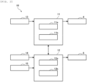
- Fig. 2 is a block diagram illustrating exemplary functional configurations of the first controller 11 and the second controller 12 in the control system 10.
- the first controller 11 includes a communication section 11a and a control section 11b, for example.
- the communication section 11a communicates with each of the devices in the motorcycle 1.
- the communication section 11a acquires information on the accelerator operation by the rider from the accelerator operation unit 13.
- the communication section 11a communicates with the second controller 12.
- the control section 11b controls the operation of the engine 4 by outputting a control command to the engine 4.
- the control section 11b basically controls the torque of the engine 4 to match the rider's requested torque.
- the rider's requested torque can be generated on the basis of various physical quantities, such as information on the accelerator operation and an engine speed, that are observed or estimated by the first controller 11.
- the second controller 12 includes a communication section 12a and a control section 12b, for example.
- the communication section 12a communicates with each of the devices in the motorcycle 1.
- the communication section 12a acquires information on the rotational frequencies of the wheels from the front-wheel rotational frequency sensor 14 and the rear-wheel rotational frequency sensor 15.
- the communication section 12a communicates with the first controller 11.
- the control section 12b controls the operation of the hydraulic pressure control unit 5 by outputting a control command to the hydraulic pressure control unit 5.
- traction control is executed when the first controller 11 and the second controller 12 execute processing cooperatively.
- the traction control is control to mitigate spinning of the drive wheel (more specifically, the rear wheel 3) or a wheelie that occurs to the motorcycle 1.
- the torque of the engine 4 is controlled to mitigate spinning of the rear wheel 3 or the wheelie.
- the second controller 12 determines and sends reference torque of the engine 4 to the first controller 11. Then, the first controller 11 executes torque suppression control to suppress the torque of the engine 4 on the basis of the reference torque received from the second controller 12.
- Fig. 3 is a flowchart illustrating an exemplary processing procedure for initiation and termination of the pre-control that is executed by the control system 10.
- Step S101 in Fig. 3 corresponds to initiation of a control flow illustrated in Fig. 3 .
- a detailed description on the pre-control will be made below with reference to Fig. 4 .
- the pre-control initiation condition is that the requested torque by the rider of the motorcycle 1 exceeds a threshold value.
- the pre-control is initiated not on the basis of a degree of a change in the torque of the engine 4.
- the pre-control initiation condition is a condition that is not based on the degree of the change in the torque of the engine 4.
- step S104 the control system 10 determines whether a pre-control termination condition is satisfied. If it is determined that the pre-control termination condition is satisfied (step S104/YES), the processing proceeds to step S105. In step S105, the pre-control is terminated, and the processing returns to step S102. On the other hand, if it is determined that the pre-control termination condition is not satisfied (step S104/NO), the processing in step S104 is repeated.
- the reference torque is determined on the basis of the torque of the engine 4 (more specifically, the torque of the engine 4 in a last calculation cycle) and follows a change in the torque of the engine 4.
- the reference torque has a higher value than the torque of the engine 4 in the last calculation cycle.
- step S204 the first controller 11 determines whether the requested torque by the rider of the motorcycle 1 exceeds the reference torque.
- Fig. 5 is a graph illustrating exemplary changes in various state amounts at the time when pre-control according to a comparative example is executed.
- a horizontal axis represents time t, and the changes in the various state amounts are illustrated.
- the state amounts illustrated in Fig. 5 are rider's requested torque TR and torque TA and reference torque TS of the engine 4 (more specifically, reference torque TS2 as the internal information of the second controller 12 and reference torque TS1 as the internal information of the first controller 11).
- the torque TA is torque that is actually output from the engine 4 (that is, actual torque).
- a pre-control initiation condition differs from that in this embodiment.
- the pre-control initiation condition is basically that a degree of a change in the torque TA of the engine 4 exceeds a reference degree of a change.
- the pre-control initiation condition another condition that the torque TA is higher than a reference value, or the like may be added.
- the first controller 11 starts receiving the reference torque TS from the second controller 12. Consequently, at the time point t12, the reference torque TS1 as the internal information of the first controller 11 starts changed in a similar manner to the change in the reference torque TS2.
- the torque suppression control in which the torque TA of the engine 4 is restricted to the reference torque TS or lower, is executed in association with the initiation of the pre-control.
- the first controller 11 initiates the torque suppression control at the time point t12.
- Fig. 6 is a graph illustrating exemplary changes in the various state amounts at the time when the pre-control according to this embodiment is executed. Similar to Fig. 5 , in Fig. 6 , a horizontal axis represents the time t, and the changes in the various state amounts (more specifically, the requested torque TR and the torque TA and the reference torque TS of the engine 4) are illustrated. A change in the requested torque TR in the example illustrated in Fig. 6 is the same as the change in the requested torque TR in the example illustrated in Fig. 5 .
- the pre-control initiation condition is satisfied. Consequently, the pre-control is initiated.
- the threshold value TH is set to a value that is small enough to determine whether the rider is performing the accelerator operation.
- the second controller 12 initiates the processing to determine the reference torque TS2.
- the pre-control is initiated not on the basis of the degree of the change in the torque TA of the engine 4.
- the pre-control is initiated at a time point prior to a time point at which the torque TA is rapidly increased.
- the second controller 12 determines the reference torque TS2 on the basis of the torque TA (more specifically, the torque TA in the last calculation cycle) such that the reference torque TS2 follows the change in the torque TA.
- the above-described two types of the delays are taken into consideration.
- the processing executed by the control system 10 is not limited to the above example.
- the above description has been made on the example in which the reference torque TS is determined on the basis of the sum of the two types of the delays that are the delay in the communication between the first controller 11 and the second controller 12 and the delay until the control command output to the engine 4 by the first controller 11 is reflected to the torque TA.
- the reference torque TS may be determined not on the basis of one of the two types of the delays, for example.
- the pre-control is executed in which the second controller 12 determines and sends the reference torque TS of the drive source (the engine 4 in the above example) to the first controller 11 and the first controller 11 executes the torque suppression control to suppress the torque TA on the basis of the reference torque TS received from the second controller 12.
- the torque TA does not show the reduction tendency.
- the occurrence of such a phenomenon is suppressed that the torque TA is rapidly reduced. Therefore, the safety can be improved without impairing the natural feeling obtained by the rider of the motorcycle 1 from the throttle operation.
- the torque suppression control is executed in the case where the requested torque TR by the rider of the motorcycle 1 exceeds the reference torque TS.
- the torque TA is appropriately restricted to the reference torque TS or lower.
- the pre-control is initiated not on the basis of the degree of the change in the torque TA.
- the pre-control can be initiated at the time point prior to the time point at which the torque TA is rapidly increased. Therefore, at the initiation of the torque suppression control, it is possible to appropriately suppress the occurrence of the phenomenon that the torque TA is rapidly reduced due to the delay in the communication between the controllers, or the like.
- the pre-control is initiated in the case where the requested torque TR by the rider of the motorcycle 1 exceeds the threshold value TH.
- the pre-control is appropriately initiated at the time point prior to the time point at which the torque TA is rapidly increased. Therefore, at the initiation of the torque suppression control, it is possible to appropriately suppress the occurrence of the phenomenon that the torque TA is rapidly reduced due to the delay in the communication between the controllers, or the like.
- the pre-control is terminated. In this way, it is possible to suppress the execution of the pre-control in a situation where the accelerator operation by the rider is canceled and the torque TA does not have to be suppressed.
- the pre-control in the case where the requested torque TR by the rider of the motorcycle 1 falls below the reference torque TS during the pre-control, the pre-control is terminated. In this way, it is possible to suppress the execution of the pre-control in a situation where the rider's requested torque TR falls below the reference torque TS and the torque TA does not have to be suppressed.
- the second controller 12 is the controller for the hydraulic pressure control unit 5.
- the first controller 11 as the controller for the drive source (the engine 4 in the above example)
- the second controller 12 as the controller for the hydraulic pressure control unit 5
- the invention is not limited to the embodiment that has been described. For example, only a part of the embodiment may be implemented.
- the execution condition of the torque suppression control in the pre-control may be other than the condition that the requested torque TR exceeds the reference torque TS.
- the pre-control initiation condition may be one of the condition that the requested torque TR by the rider of the motorcycle 1 exceeds the threshold value TH, the condition that is not based on the degree of the change in the torque TA of the engine 4, and a condition other than these, or may include plural types of the appropriate conditions.
- the pre-control termination condition may be one of the condition that the accelerator operation by the rider of the motorcycle 1 is canceled, the condition that the requested torque TR by the rider of the motorcycle 1 falls below the reference torque TS, the condition that the main control is initiated, and a condition other than these, or may include plural types of the appropriate conditions.
- any of the examples that have been described as the examples of each of the conditions may appropriately be combined.
Landscapes
- Engineering & Computer Science (AREA)
- Chemical & Material Sciences (AREA)
- Combustion & Propulsion (AREA)
- Mechanical Engineering (AREA)
- Transportation (AREA)
- Automation & Control Theory (AREA)
- General Engineering & Computer Science (AREA)
- Control Of Vehicle Engines Or Engines For Specific Uses (AREA)
Abstract
The invention obtains a control system and a control method capable of improving safety without impairing natural feeling obtained by a motorcycle rider from a throttle operation.
In regard to the control system and the control method according to the invention, the control system includes a first controller controlling torque TA of a drive source of a motorcycle and a second controller communicating with the first controller. Prior to main control in which torque suppression control is executed at the time of detecting spinning of a drive wheel or a wheelie, pre-control is executed in which the second controller determines and sends reference torque TS of the drive source to the first controller and the first controller executes the torque suppression control to suppress torque on the basis of the reference torque TS received from the second controller. In the torque suppression control in the pre-control, the torque TA does not show a reduction tendency.
Description
- This disclosure relates to a control system and a control method capable of improving safety without impairing natural feeling obtained by a motorcycle rider from a throttle operation.
- Conventionally, the following method has been proposed. In the method, target torque at the time of controlling engine torque is determined in order to mitigate spinning of a drive wheel or a wheelie of a motorcycle caused by the excess engine torque. For example, the following technique is disclosed in
PTL 1. Control is intervened to reduce the engine torque in comparison with a case without the control not only when occurrence of spinning of a rear wheel as the drive wheel or the wheelie is determined, but also when an increase amount of a driver's requested torque per unit time becomes a threshold value or higher. - PTL 1:
JP2019-019784A - Hereinafter, traction control that intervenes when spinning of the drive wheel or the wheelie is detected will be referred to as main control. Meanwhile, pre-control is the traction control that grasps a sign of the occurrence of spinning of the drive wheel or the wheelie from behavior of a signal associated with torque of a drive source and intervenes before spinning of the drive wheel or the wheelie is detected. By the way, there is a case where the torque of the drive source is excessively suppressed and rapidly reduced at initiation of the pre-control. In particular, such a phenomenon is likely to occur when a controller that controls the torque of the drive source differs from a controller that executes processing to determine a control command to the drive source in the pre-control due to delayed communication between the controllers. Such a phenomenon becomes a cause of impairing natural feeling obtained by the rider from a throttle operation. Thus, it has been problematic to answer a request for improved vehicle stability while promoting intervention by the pre-control.
- The invention has been made with the above-described problem as the background and therefore obtains a control system and a control method capable of improving safety without impairing natural feeling obtained by a motorcycle rider from a throttle operation.
- A control system according to the invention is a control system executing traction control to mitigate spinning of a drive wheel or a wheelie that occurs to a motorcycle, and includes a first controller controlling torque of a drive source of the motorcycle and a second controller communicating with the first controller. When spinning of the drive wheel or the wheelie is detected, main control is executed in which the second controller determines and sends reference torque of the drive source to the first controller and the first controller executes torque suppression control to suppress the torque on the basis of the reference torque received from the second controller. Prior to the main control, pre-control is executed in which the second controller determines and sends the reference torque of the drive source to the first controller and the first controller executes the torque suppression control to suppress the torque on the basis of the reference torque received from the second controller. In the torque suppression control in the pre-control, the torque does not show a reduction tendency.
- A control method according to the invention is a control method for a control system executing traction control to mitigate spinning of a drive wheel or a wheelie that occurs to a motorcycle, and the control system includes a first controller controlling torque of a drive source of the motorcycle and a second controller communicating with the first controller. The control method includes: when spinning of the drive wheel or the wheelie is detected, executing main control in which the second controller determines and sends reference torque of the drive source to the first controller and the first controller executes torque suppression control to suppress the torque on the basis of the reference torque received from the second controller; and, prior to the main control, executing pre-control in which the second controller determines and sends the reference torque of the drive source to the first controller and the first controller executes the torque suppression control to suppress the torque on the basis of the reference torque received from the second controller. In the torque suppression control in the pre-control, the torque does not show a reduction tendency.
- In regard to the control system and the control method according to the invention, the control system includes the first controller controlling the torque of the drive source of the motorcycle and the second controller communicating with the first controller. When spinning of the drive wheel or the wheelie is detected, the main control is executed in which the second controller determines and sends the reference torque of the drive source to the first controller and the first controller executes the torque suppression control to suppress the torque on the basis of the reference torque received from the second controller. Prior to the main control, the pre-control is executed in which the second controller determines and sends the reference torque of the drive source to the first controller and the first controller executes the torque suppression control to suppress the torque on the basis of the reference torque received from the second controller. In the torque suppression control in the pre-control, the torque does not show the reduction tendency. In this way, occurrence of such a phenomenon is suppressed that the torque of the drive source is excessively suppressed and rapidly reduced at initiation of the torque suppression control in the pre-control. Therefore, safety can be improved without impairing natural feeling obtained by a motorcycle rider from a throttle operation.
-
-
Fig. 1 is a schematic view illustrating an outline configuration of a motorcycle according to an embodiment of the invention. -
Fig. 2 is a block diagram illustrating exemplary functional configurations of a first controller and a second controller in a control system according to the embodiment of the invention. -
Fig. 3 is a flowchart illustrating an exemplary processing procedure for initiation and termination of pre-control that is executed by the control system according to the embodiment of the invention. -
Fig. 4 is a flowchart illustrating an exemplary processing procedure during the pre-control that is executed by the control system according to the embodiment of the invention. -
Fig. 5 is a graph illustrating exemplary changes in various state amounts at the time when pre-control according to a comparative example is executed. -
Fig. 6 is a graph illustrating exemplary changes in the various state amounts at the time when the pre-control according to the embodiment of the invention is executed. Description of Embodiments - A description will hereinafter be made on a control system and a control method according to the invention with reference to the drawings.
- The following description will be made on a control system used for a two-wheeled motorcycle (see a
motorcycle 1 inFig. 1 ). However, a vehicle as a control target of the control system according to the invention may be a motorcycle other than the two-wheeled motorcycle. The motorcycles include a vehicle having an engine as a power source, a vehicle having an electric motor as the power source, and the like. Examples of the motorcycles are a motorbike, a scooter, and an electric scooter. - A configuration, operation, and the like, which will be described below, merely constitute one example. The control system and the control method according to the invention are not limited to a case with such a configuration, such operation, and the like.
- The same or similar description will appropriately be simplified or will not be made below. In the drawings, the same or similar members or portions will not be denoted by a reference sign or will be denoted by the same reference sign. A detailed structure will appropriately be illustrated in a simplified manner or will not be illustrated.
- A description will be made on a configuration of the
motorcycle 1 according to an embodiment of the invention with reference toFig. 1 andFig. 2 . -
Fig. 1 is a schematic view illustrating an outline configuration of themotorcycle 1. As illustrated inFig. 1 , themotorcycle 1 includes afront wheel 2, arear wheel 3, anengine 4, and a hydraulicpressure control unit 5. Theengine 4 corresponds to an example of a drive source of themotorcycle 1. However, the drive source of themotorcycle 1 may be the electric motor. - The
engine 4 can output power for driving therear wheel 3 as a drive wheel. For example, theengine 4 is provided with: one or plural cylinders, each of which is formed with a combustion chamber therein; a fuel injector that injects fuel into the combustion chamber; and an ignition plug. When the fuel is injected from the fuel injector, air-fuel mixture containing air and the fuel is produced in the combustion chamber, and the air-fuel mixture is then ignited by the ignition plug and burned. Consequently, a piston provided in the cylinder reciprocates to cause a crankshaft to rotate. A throttle valve is provided to an intake pipe of theengine 4, and an intake air amount to the combustion chamber varies according to a throttle opening amount as an opening amount of the throttle valve. - The hydraulic
pressure control unit 5 is a unit that has a function to control a braking force generated on the wheel. For example, the hydraulicpressure control unit 5 includes components (for example, a control valve and a pump) that are provided on an oil channel connecting a master cylinder and a wheel cylinder and control a brake hydraulic pressure in the wheel cylinder. By controlling operation of the components of the hydraulicpressure control unit 5, the braking force generated on the wheel is controlled. The hydraulicpressure control unit 5 may control the braking force generated on each of thefront wheel 2 and therear wheel 3 or may only control the braking force generated on one of thefront wheel 2 and therear wheel 3. - As illustrated in
Fig. 1 , themotorcycle 1 further includes acontrol system 10. Thecontrol system 10 is a system that controls behavior of themotorcycle 1. Thecontrol system 10 includes afirst controller 11, asecond controller 12, anaccelerator operation unit 13, a front-wheelrotational frequency sensor 14, and a rear-wheelrotational frequency sensor 15. - The
first controller 11 controls torque of theengine 4 by controlling operation of theengine 4. Thesecond controller 12 controls the braking force generated on the wheel by controlling operation of the hydraulicpressure control unit 5. For example, each of thefirst controller 11 and thesecond controller 12 is partially or entirely constructed of a microcomputer, a microprocessor unit, or the like. Alternatively, each of thefirst controller 11 and thesecond controller 12 may partially or entirely be one whose firmware and the like can be updated, or may be a program module or the like that is executed by a command from a CPU or the like, for example. - The
second controller 12 corresponds to an example of a different controller from thefirst controller 11 that controls the torque of theengine 4. That is, thesecond controller 12 may be a controller other than the controller for the hydraulicpressure control unit 5. However, in the present specification, a description will mainly be made on an example in which thesecond controller 12 is the controller for the hydraulicpressure control unit 5. - The
accelerator operation unit 13 accepts an accelerator operation by a rider of themotorcycle 1. More specifically, theaccelerator operation unit 13 is an accelerator grip that is provided to a handlebar of themotorcycle 1 and is rotated by the rider. - The front-wheel
rotational frequency sensor 14 is a wheel rotational frequency sensor that detects a rotational frequency of the front wheel 2 (for example, a rotational frequency of thefront wheel 2 per unit time [rpm], a travel distance of thefront wheel 2 per unit time [km/h], or the like), and outputs a detection result. The front-wheelrotational frequency sensor 14 may detect another physical quantity that can substantially be converted to the rotational frequency of thefront wheel 2. The front-wheelrotational frequency sensor 14 is provided to thefront wheel 2. - The rear-wheel
rotational frequency sensor 15 is a wheel rotational frequency sensor that detects a rotational frequency of the rear wheel 3 (for example, the rotational frequency of therear wheel 3 per unit time [rpm], a travel distance of therear wheel 3 per unit time [km/h], or the like), and outputs a detection result. The rear-wheelrotational frequency sensor 15 may detect another physical quantity that can substantially be converted to the rotational frequency of therear wheel 3. The rear-wheelrotational frequency sensor 15 is provided to therear wheel 3. -
Fig. 2 is a block diagram illustrating exemplary functional configurations of thefirst controller 11 and thesecond controller 12 in thecontrol system 10. - As illustrated in
Fig. 2 , thefirst controller 11 includes acommunication section 11a and acontrol section 11b, for example. Thecommunication section 11a communicates with each of the devices in themotorcycle 1. For example, thecommunication section 11a acquires information on the accelerator operation by the rider from theaccelerator operation unit 13. In addition, for example, thecommunication section 11a communicates with thesecond controller 12. Thecontrol section 11b controls the operation of theengine 4 by outputting a control command to theengine 4. Thecontrol section 11b basically controls the torque of theengine 4 to match the rider's requested torque. The rider's requested torque can be generated on the basis of various physical quantities, such as information on the accelerator operation and an engine speed, that are observed or estimated by thefirst controller 11. - As illustrated in
Fig. 2 , thesecond controller 12 includes acommunication section 12a and acontrol section 12b, for example. Thecommunication section 12a communicates with each of the devices in themotorcycle 1. For example, thecommunication section 12a acquires information on the rotational frequencies of the wheels from the front-wheelrotational frequency sensor 14 and the rear-wheelrotational frequency sensor 15. In addition, for example, thecommunication section 12a communicates with thefirst controller 11. Thecontrol section 12b controls the operation of the hydraulicpressure control unit 5 by outputting a control command to the hydraulicpressure control unit 5. - In the
control system 10, traction control is executed when thefirst controller 11 and thesecond controller 12 execute processing cooperatively. The traction control is control to mitigate spinning of the drive wheel (more specifically, the rear wheel 3) or a wheelie that occurs to themotorcycle 1. In main control of the traction control, when spinning of therear wheel 3 as the drive wheel or the wheelie actually occurs, the torque of theengine 4 is controlled to mitigate spinning of therear wheel 3 or the wheelie. More specifically, in the main control, when spinning of therear wheel 3 or the wheelie is detected, thesecond controller 12 determines and sends reference torque of theengine 4 to thefirst controller 11. Then, thefirst controller 11 executes torque suppression control to suppress the torque of theengine 4 on the basis of the reference torque received from thesecond controller 12. - Furthermore, in the
control system 10, when thefirst controller 11 and thesecond controller 12 execute the processing cooperatively, pre-control is executed as the traction control prior to the main control. The pre-control is executed in a situation where spinning of therear wheel 3 or the wheelie does not occur. The pre-control is control to avoid spinning of therear wheel 3 or the wheelie from occurring by suppressing a rapid increase in the torque of theengine 4. In the pre-control, the torque suppression control to suppress the torque of theengine 4 is executed. - In this embodiment, by devising the pre-control, such a phenomenon is suppressed that the torque of the
engine 4 is excessively suppressed and is thereby rapidly reduced in the pre-control. As a result, safety is improved without impairing natural feeling obtained by the rider of themotorcycle 1 from the throttle operation. A detailed description will hereinafter be made on the pre-control according to this embodiment. - A description will be made on operation of the
control system 10 according to the embodiment of the invention with reference toFig. 3 to Fig. 6 . -
Fig. 3 is a flowchart illustrating an exemplary processing procedure for initiation and termination of the pre-control that is executed by thecontrol system 10. Step S101 inFig. 3 corresponds to initiation of a control flow illustrated inFig. 3 . A detailed description on the pre-control will be made below with reference toFig. 4 . - Processing in each step of the control flow illustrated in
Fig. 3 is executed by thesecond controller 12, for example. - When the control flow illustrated in
Fig. 3 is initiated, in step S102, thecontrol system 10 determines whether a pre-control initiation condition is satisfied. If it is determined that the pre-control initiation condition is satisfied (step S102/YES), the processing proceeds to step S103. In step S103, the pre-control is initiated. On the other hand, if it is determined that the pre-control initiation condition is not satisfied (step S102/NO), the processing in step S102 is repeated. - For example, the pre-control initiation condition is that the requested torque by the rider of the
motorcycle 1 exceeds a threshold value. In this case, more specifically, in the case where the requested torque by the rider of themotorcycle 1 exceeds the threshold value, the pre-control is initiated not on the basis of a degree of a change in the torque of theengine 4. Just as described, the pre-control initiation condition is a condition that is not based on the degree of the change in the torque of theengine 4. - After step S103, in step S104, the
control system 10 determines whether a pre-control termination condition is satisfied. If it is determined that the pre-control termination condition is satisfied (step S104/YES), the processing proceeds to step S105. In step S105, the pre-control is terminated, and the processing returns to step S102. On the other hand, if it is determined that the pre-control termination condition is not satisfied (step S104/NO), the processing in step S104 is repeated. - Various conditions can be used as the pre-control termination condition. For example, as the pre-control termination condition, such a condition is used that the accelerator operation by the rider of the
motorcycle 1 is canceled. Alternatively, for example, as the pre-control termination condition, such a condition is used that the requested torque by the rider of themotorcycle 1 falls below the reference torque. In the torque suppression control in the pre-control, the torque of theengine 4 is restricted to the reference torque or lower. In the case where the requested torque is lower than the reference torque, a magnitude of the torque corresponding to the requested torque has to be output from theengine 4. For this reason, such a termination condition is used. Further alternatively, for example, as the pre-control termination condition, such a condition is used that the main control has been initiated. -
Fig. 4 is a flowchart illustrating an exemplary processing procedure during the pre-control that is executed by thecontrol system 10. Step S201 inFig. 4 corresponds to initiation of a control flow illustrated inFig. 4 . Step S206 inFig. 4 corresponds to termination of the control flow illustrated inFig. 4 . The control flow illustrated inFig. 4 is repeated during the pre-control. - When the control flow illustrated in
Fig. 4 is initiated, in step S202, thesecond controller 12 determines the reference torque of theengine 4. As described above, in the torque suppression control in the pre-control, the torque of theengine 4 is restricted to the reference torque or lower. Thus, the reference torque corresponds to an upper limit value of the torque of theengine 4. - A detailed description on processing to determine the reference torque will be made below with reference to
Fig. 6 . Basically, the reference torque is determined on the basis of the torque of the engine 4 (more specifically, the torque of theengine 4 in a last calculation cycle) and follows a change in the torque of theengine 4. The reference torque has a higher value than the torque of theengine 4 in the last calculation cycle. - After step S202, in step S203, the
second controller 12 sends the determined reference torque to thefirst controller 11. Then, thefirst controller 11 receives the reference torque sent from thesecond controller 12. - Here, there is a time lag between a time point at which the
second controller 12 starts sending the information and a time point at which thefirst controller 11 finishes receiving the information from thesecond controller 12. Consequently, a delay occurs until the reference torque as internal information of thesecond controller 12 is reflected as internal information of thefirst controller 11. Such a delay will be referred to as a delay in communication between thefirst controller 11 and thesecond controller 12. - After step S203, in step S204, the
first controller 11 determines whether the requested torque by the rider of themotorcycle 1 exceeds the reference torque. - If it is determined that the rider's requested torque exceeds the reference torque (step S204/YES), the processing proceeds to step S205. In step S205, the
first controller 11 executes the torque suppression control, and the control flow illustrated inFig. 4 is then terminated. In the torque suppression control, the torque of theengine 4 is restricted to the reference torque or lower. If it is determined that the rider's requested torque does not exceed the reference torque (step S204/NO), the control flow illustrated inFig. 4 is terminated. -
Fig. 5 is a graph illustrating exemplary changes in various state amounts at the time when pre-control according to a comparative example is executed. InFig. 5 , a horizontal axis represents time t, and the changes in the various state amounts are illustrated. The state amounts illustrated inFig. 5 are rider's requested torque TR and torque TA and reference torque TS of the engine 4 (more specifically, reference torque TS2 as the internal information of thesecond controller 12 and reference torque TS1 as the internal information of the first controller 11). The torque TA is torque that is actually output from the engine 4 (that is, actual torque). - In the comparative example, a pre-control initiation condition differs from that in this embodiment. In the comparative example, the pre-control initiation condition is basically that a degree of a change in the torque TA of the
engine 4 exceeds a reference degree of a change. In practice, as the pre-control initiation condition, another condition that the torque TA is higher than a reference value, or the like may be added. - In the example illustrated in
Fig. 5 , the torque TA of theengine 4 is increased along with an increase in the requested torque TR until a time point t11. Then, at the time point t11, the degree of the change in the torque TA exceeds the reference degree of the change, and the pre-control initiation condition is satisfied. Consequently, the pre-control is initiated. Thus, at the time point t11, thesecond controller 12 initiates processing to determine the reference torque TS2. In the comparative example, thesecond controller 12 determines the reference torque TS2 such that the reference torque TS2 is changed from the torque TA at the pre-control initiation time point t11 with a gradient of change that is not excessively steep. - Then, at a time point t12 at which the delay in the communication between the
first controller 11 and thesecond controller 12 elapses, thefirst controller 11 starts receiving the reference torque TS from thesecond controller 12. Consequently, at the time point t12, the reference torque TS1 as the internal information of thefirst controller 11 starts changed in a similar manner to the change in the reference torque TS2. In the comparative example, the torque suppression control, in which the torque TA of theengine 4 is restricted to the reference torque TS or lower, is executed in association with the initiation of the pre-control. Thus, thefirst controller 11 initiates the torque suppression control at the time point t12. - Here, there is a time lag between a time point at which the
first controller 11 outputs the control command to theengine 4 and a time point at which the control command is reflected to the torque TA. Just as described, a delay occurs until the control command output to theengine 4 by thefirst controller 11 is reflected to the torque TA. Accordingly, the torque TA actually starts suppressed at a time point t13 at which the delay elapses from the time point t12. - In the example illustrated in
Fig. 5 , in a period between the pre-control initiation time point t11 and the time point t13, at which the torque TA actually starts suppressed, there is a delay that is a sum of the delay in the communication between thefirst controller 11 and thesecond controller 12 and the delay until the control command output to theengine 4 by thefirst controller 11 is reflected to the torque TA. Consequently, as illustrated inFig. 5 , the torque TA that is increased from the time point t11 to the time point t13 is rapidly reduced at the time point t13. Such a phenomenon impairs the natural feeling obtained by the rider from the throttle operation. -
Fig. 6 is a graph illustrating exemplary changes in the various state amounts at the time when the pre-control according to this embodiment is executed. Similar toFig. 5 , inFig. 6 , a horizontal axis represents the time t, and the changes in the various state amounts (more specifically, the requested torque TR and the torque TA and the reference torque TS of the engine 4) are illustrated. A change in the requested torque TR in the example illustrated inFig. 6 is the same as the change in the requested torque TR in the example illustrated inFig. 5 . - In the example illustrated in
Fig. 6 , at a time point t21, the requested torque TR exceeds a threshold value TH, and the pre-control initiation condition is satisfied. Consequently, the pre-control is initiated. For example, the threshold value TH is set to a value that is small enough to determine whether the rider is performing the accelerator operation. Then, at the time point t21, thesecond controller 12 initiates the processing to determine the reference torque TS2. Just as described, in this embodiment, the pre-control is initiated not on the basis of the degree of the change in the torque TA of theengine 4. Thus, the pre-control is initiated at a time point prior to a time point at which the torque TA is rapidly increased. - In this embodiment, the
second controller 12 determines the reference torque TS2 on the basis of the torque TA (more specifically, the torque TA in the last calculation cycle) such that the reference torque TS2 follows the change in the torque TA. As will be described below, in the processing to determine the reference torque TS2 in this embodiment, the above-described two types of the delays are taken into consideration. - Then, at a time point t22 at which the delay in the communication between the
first controller 11 and thesecond controller 12 elapses from the time point t21, thefirst controller 11 starts receiving the reference torque TS from thesecond controller 12. Consequently, at the time point t22, the reference torque TS1 as the internal information of thefirst controller 11 starts changed in the similar manner to the change in the reference torque TS2. Thereafter, the requested torque TR is rapidly increased and, at a time point t23, exceeds the reference torque TS1. Consequently, at the time point t23, thefirst controller 11 determines that the requested torque TR exceeds the reference torque TS1, and initiates the torque suppression control. - Then, at a time point t24 at which the delay until the control command output to the
engine 4 by thefirst controller 11 is reflected to the torque TA elapses from the time point t23, the torque TA actually starts suppressed. In this embodiment, thesecond controller 12 determines a value that is high to some extent as the reference torque TS2 in consideration of the delay as the sum of the delay in the communication between thefirst controller 11 and thesecond controller 12 and the delay until the control command output to theengine 4 by thefirst controller 11 is reflected to the torque TA. As a result, occurrence of such a phenomenon is suppressed that the torque TA exceeds the reference torque TS1 in a period from the torque suppression control initiation time point t23 to the time point t24 at which the torque TA actually starts suppressed. - In this way, at the time point t24, at which the torque TA actually starts suppressed, the torque TA is not reduced but continues to be increased. Just as described, in this embodiment, the torque TA does not show a reduction tendency in the torque suppression control. As a result, at the initiation of the torque suppression control, the occurrence of such a phenomenon is suppressed that the torque TA is rapidly reduced. Therefore, it is possible to ensure the natural feeling obtained by the rider of the
motorcycle 1 from the throttle operation. The reduction tendency of the torque TA may include the reduction in the torque TA with ups-downs in short cycles. - The above description has been made on the processing example of the
control system 10 with reference toFig. 3 to Fig. 6 . However, the processing executed by thecontrol system 10 is not limited to the above example. For example, the above description has been made on the example in which the reference torque TS is determined on the basis of the sum of the two types of the delays that are the delay in the communication between thefirst controller 11 and thesecond controller 12 and the delay until the control command output to theengine 4 by thefirst controller 11 is reflected to the torque TA. The reference torque TS may be determined not on the basis of one of the two types of the delays, for example. - A description will be made on effects of the
control system 10 according to the embodiment of the invention. - In the
control system 10, prior to the main control, the pre-control is executed in which thesecond controller 12 determines and sends the reference torque TS of the drive source (theengine 4 in the above example) to thefirst controller 11 and thefirst controller 11 executes the torque suppression control to suppress the torque TA on the basis of the reference torque TS received from thesecond controller 12. In the torque suppression control in the pre-control, the torque TA does not show the reduction tendency. As a result, at the initiation of the torque suppression control, the occurrence of such a phenomenon is suppressed that the torque TA is rapidly reduced. Therefore, the safety can be improved without impairing the natural feeling obtained by the rider of themotorcycle 1 from the throttle operation. - Preferably, in the
control system 10, in the pre-control, in the case where the requested torque TR by the rider of themotorcycle 1 exceeds the reference torque TS, the torque suppression control is executed. Thus, in the case where the rider's requested torque TR is higher than the reference torque TS, the torque TA is appropriately restricted to the reference torque TS or lower. - Preferably, in the
control system 10, the pre-control is initiated not on the basis of the degree of the change in the torque TA. In this way, the pre-control can be initiated at the time point prior to the time point at which the torque TA is rapidly increased. Therefore, at the initiation of the torque suppression control, it is possible to appropriately suppress the occurrence of the phenomenon that the torque TA is rapidly reduced due to the delay in the communication between the controllers, or the like. - Preferably, in the
control system 10, in the case where the requested torque TR by the rider of themotorcycle 1 exceeds the threshold value TH, the pre-control is initiated. In this way, the pre-control is appropriately initiated at the time point prior to the time point at which the torque TA is rapidly increased. Therefore, at the initiation of the torque suppression control, it is possible to appropriately suppress the occurrence of the phenomenon that the torque TA is rapidly reduced due to the delay in the communication between the controllers, or the like. - Preferably, in the
control system 10, in the case where the accelerator operation by the rider of themotorcycle 1 is canceled during the pre-control, the pre-control is terminated. In this way, it is possible to suppress the execution of the pre-control in a situation where the accelerator operation by the rider is canceled and the torque TA does not have to be suppressed. - Preferably, in the
control system 10, in the case where the requested torque TR by the rider of themotorcycle 1 falls below the reference torque TS during the pre-control, the pre-control is terminated. In this way, it is possible to suppress the execution of the pre-control in a situation where the rider's requested torque TR falls below the reference torque TS and the torque TA does not have to be suppressed. - Preferably, in the
control system 10, the reference torque TS for the pre-control is determined on the basis of the delay until the control command output to thedrive source 4 by thefirst controller 11 is reflected to the torque TA. In this way, it is possible to appropriately suppress the torque TA from exceeding the reference torque TS, and the torque TA is increased in the period from the time point at the initiation of the torque suppression control to the time point at which the torque TA actually starts suppressed. As a result, at the initiation of the torque suppression control, the occurrence of the phenomenon that the torque TA is rapidly reduced is appropriately suppressed. Therefore, the safety is appropriately improved without impairing the natural feeling obtained by the rider of themotorcycle 1 from the throttle operation. - Preferably, in the
control system 10, the reference torque TS for the pre-control is determined on the basis of the delay in the communication between thefirst controller 11 and thesecond controller 12. In this way, it is possible to appropriately suppress the torque TA from exceeding the reference torque TS, and the torque TA is increased in the period from the time point at the initiation of the torque suppression control to the time point at which the torque TA actually starts suppressed. As a result, at the initiation of the torque suppression control, the occurrence of the phenomenon that the torque TA is rapidly reduced is appropriately suppressed. Therefore, the safety is appropriately improved without impairing the natural feeling obtained by the rider of themotorcycle 1 from the throttle operation. - Preferably, in the
control system 10, thesecond controller 12 is the controller for the hydraulicpressure control unit 5. Thus, in themotorcycle 1 in which the pre-control and the traction control are executed by thefirst controller 11 as the controller for the drive source (theengine 4 in the above example) and thesecond controller 12 as the controller for the hydraulicpressure control unit 5, the safety can be improved without impairing the natural feeling obtained by the rider from the throttle operation. - The invention is not limited to the embodiment that has been described. For example, only a part of the embodiment may be implemented.
- For example, the execution condition of the torque suppression control in the pre-control may be other than the condition that the requested torque TR exceeds the reference torque TS. The pre-control initiation condition may be one of the condition that the requested torque TR by the rider of the
motorcycle 1 exceeds the threshold value TH, the condition that is not based on the degree of the change in the torque TA of theengine 4, and a condition other than these, or may include plural types of the appropriate conditions. The pre-control termination condition may be one of the condition that the accelerator operation by the rider of themotorcycle 1 is canceled, the condition that the requested torque TR by the rider of themotorcycle 1 falls below the reference torque TS, the condition that the main control is initiated, and a condition other than these, or may include plural types of the appropriate conditions. As a combination of the execution condition for the torque suppression control in the pre-control, the pre-control initiation condition, and the pre-control termination condition, any of the examples that have been described as the examples of each of the conditions may appropriately be combined. -
- 1: Motorcycle
- 2: Front wheel
- 3: Rear wheel (drive wheel)
- 4: Engine (drive source)
- 5: Hydraulic pressure control unit
- 10: Control system
- 11: First controller
- 11a: Communication section
- 11b: Control section
- 12: Second controller
- 12a: Communication section
- 12b: Control section
- 13: Accelerator operation section
- 14: Front-wheel rotational frequency sensor
- 15: Rear-wheel rotational frequency sensor
- TA: Torque
- TH: Threshold value
- TR: Requested torque
- TS: Reference torque
- TS1: Reference torque
- TS2: Reference torque
Claims (10)
- A control system (10) executing traction control to mitigate spinning of a drive wheel (3) or a wheelie that occurs to a motorcycle (1), the control system comprising:a first controller (11) controlling torque (TA) of a drive source (4) of the motorcycle (1); anda second controller (12) communicating with the first controller (11), whereinwhen the spinning of the drive wheel (3) or the wheelie is detected, main control is executed in which the second controller (12) determines and sends reference torque (TS) of the drive source (4) to the first controller (11) and the first controller (11) executes torque suppression control to suppress the torque (TA) on the basis of the reference torque (TS) received from the second controller (12),prior to the main control, pre-control is executed in which the second controller (12) determines and sends the reference torque (TS) of the drive source (4) to the first controller (11) and the first controller (11) executes the torque suppression control to suppress the torque (TA) on the basis of the reference torque (TS) received from the second controller (12), andin the torque suppression control in the pre-control, the torque (TA) does not show a reduction tendency.
- The control system according to claim 1, wherein
in the pre-control, in the case where requested torque (TR) by a rider of the motorcycle (1) exceeds the reference torque (TS), the torque suppression control is executed. - The control system according to claim 1 or 2, wherein
the pre-control is initiated not on the basis of a degree of a change in the torque (TA). - The control system according to claim 1 or 2, wherein
in the case where requested torque (TR) by a rider of the motorcycle (1) exceeds a threshold value (TH), the pre-control is initiated. - The control system according to claim 1 or 2, wherein
in the case where an accelerator operation by a rider of the motorcycle (1) is canceled during execution of the pre-control, the pre-control is terminated. - The control system according to claim 1 or 2, wherein
in the case where requested torque (TR) by a rider of the motorcycle (1) falls below the reference torque (TS) during execution of the pre-control, the pre-control is terminated. - The control system according to claim 1 or 2, wherein
the reference torque (TS) for the pre-control is determined on the basis of a delay until a control command output to the drive source (4) by the first controller (11) is reflected to the torque (TA). - The control system according to claim 1 or 2, wherein
the reference torque (TS) for the pre-control is determined on the basis of a delay in communication between the first controller (11) and the second controller (12). - The control system according to claim 1 or 2, wherein
the second controller (12) is a controller for a hydraulic pressure control unit (5). - A control method for a control system (10) executing traction control to mitigate spinning of a drive wheel (3) or a wheelie that occurs to a motorcycle (1),
the control system (10) including:a first controller (11) controlling torque (TA) of a drive source (4) of the motorcycle (1); anda second controller (12) communicating with the first controller (11), the control method comprising:when the spinning of the drive wheel (3) or the wheelie is detected, executing main control in which the second controller (12) determines and sends reference torque (TS) of the drive source (4) to the first controller (11) and the first controller (11) executes torque suppression control to suppress the torque (TA) on the basis of the reference torque (TS) received from the second controller (12); andprior to the main control, executing pre-control in which the second controller (12) determines and sends the reference torque (TS) of the drive source (4) to the first controller (11) and the first controller (11) executes the torque suppression control to suppress the torque (TA) on the basis of the reference torque (TS) received from the second controller (12), whereinin the torque suppression control in the pre-control, the torque (TA) does not show a reduction tendency.
Applications Claiming Priority (2)
| Application Number | Priority Date | Filing Date | Title |
|---|---|---|---|
| JP2022090532 | 2022-06-02 | ||
| PCT/IB2023/055060 WO2023233229A1 (en) | 2022-06-02 | 2023-05-17 | Control system and control method |
Publications (1)
| Publication Number | Publication Date |
|---|---|
| EP4534372A1 true EP4534372A1 (en) | 2025-04-09 |
Family
ID=86776106
Family Applications (1)
| Application Number | Title | Priority Date | Filing Date |
|---|---|---|---|
| EP23731354.9A Pending EP4534372A1 (en) | 2022-06-02 | 2023-05-17 | Control system and control method |
Country Status (4)
| Country | Link |
|---|---|
| EP (1) | EP4534372A1 (en) |
| JP (1) | JPWO2023233229A1 (en) |
| CN (1) | CN119317563A (en) |
| WO (1) | WO2023233229A1 (en) |
Family Cites Families (4)
| Publication number | Priority date | Publication date | Assignee | Title |
|---|---|---|---|---|
| DE10238216A1 (en) * | 2002-05-03 | 2003-11-20 | Bosch Gmbh Robert | Process and device for drive slip control for a motor vehicle has stepwise reduction of engine moment when ideal values are exceeded |
| DE102009027603A1 (en) * | 2009-07-10 | 2011-01-13 | Robert Bosch Gmbh | Method for coordinating at least one drive unit |
| US9545926B2 (en) * | 2013-09-06 | 2017-01-17 | Jaguar Land Rover Limited | Vehicle control system and method for switching between powertrain control functions |
| JP7404000B2 (en) * | 2019-09-04 | 2023-12-25 | カワサキモータース株式会社 | Wheelie suppression control device |
-
2023
- 2023-05-17 WO PCT/IB2023/055060 patent/WO2023233229A1/en not_active Ceased
- 2023-05-17 JP JP2024524505A patent/JPWO2023233229A1/ja active Pending
- 2023-05-17 EP EP23731354.9A patent/EP4534372A1/en active Pending
- 2023-05-17 CN CN202380044138.9A patent/CN119317563A/en active Pending
Also Published As
| Publication number | Publication date |
|---|---|
| WO2023233229A1 (en) | 2023-12-07 |
| CN119317563A (en) | 2025-01-14 |
| JPWO2023233229A1 (en) | 2023-12-07 |
Similar Documents
| Publication | Publication Date | Title |
|---|---|---|
| EP3828044A1 (en) | Control device and control method | |
| CN106884730B (en) | Engine control device | |
| EP3741636A1 (en) | Vehicle control method, and control device for vehicle system and vehicle | |
| US10351164B2 (en) | Vehicle control device | |
| US20170145940A1 (en) | Engine control device | |
| CN107152347B (en) | Engine control device | |
| EP4173905B1 (en) | Control device and control method for controlling the behavior of a lean angle during turning | |
| CN108138673B (en) | Vehicle control device | |
| EP3415388B1 (en) | Vehicle control device | |
| EP3842654A2 (en) | Controller and control method | |
| EP3575580B1 (en) | Vehicle control device | |
| US10336364B2 (en) | Vehicle control device | |
| EP4534372A1 (en) | Control system and control method | |
| EP3342658B1 (en) | Vehicle control device | |
| US8515632B2 (en) | Driving force controller for vehicle | |
| US20180281780A1 (en) | Vehicle control device | |
| CN101495737A (en) | Vehicle driving force control device | |
| CN108622095B (en) | Vehicle control device | |
| EP4434835A2 (en) | Control device and control method | |
| JP4310658B2 (en) | Vehicle driving force control device |
Legal Events
| Date | Code | Title | Description |
|---|---|---|---|
| STAA | Information on the status of an ep patent application or granted ep patent |
Free format text: STATUS: UNKNOWN |
|
| STAA | Information on the status of an ep patent application or granted ep patent |
Free format text: STATUS: THE INTERNATIONAL PUBLICATION HAS BEEN MADE |
|
| PUAI | Public reference made under article 153(3) epc to a published international application that has entered the european phase |
Free format text: ORIGINAL CODE: 0009012 |
|
| STAA | Information on the status of an ep patent application or granted ep patent |
Free format text: STATUS: REQUEST FOR EXAMINATION WAS MADE |
|
| 17P | Request for examination filed |
Effective date: 20250106 |
|
| AK | Designated contracting states |
Kind code of ref document: A1 Designated state(s): AL AT BE BG CH CY CZ DE DK EE ES FI FR GB GR HR HU IE IS IT LI LT LU LV MC ME MK MT NL NO PL PT RO RS SE SI SK SM TR |
|
| DAV | Request for validation of the european patent (deleted) | ||
| DAX | Request for extension of the european patent (deleted) |