EP4534371A1 - Reverse control device for coupled vehicle - Google Patents
Reverse control device for coupled vehicle Download PDFInfo
- Publication number
- EP4534371A1 EP4534371A1 EP23815863.8A EP23815863A EP4534371A1 EP 4534371 A1 EP4534371 A1 EP 4534371A1 EP 23815863 A EP23815863 A EP 23815863A EP 4534371 A1 EP4534371 A1 EP 4534371A1
- Authority
- EP
- European Patent Office
- Prior art keywords
- vehicle
- control device
- towing
- reverse control
- reverse
- Prior art date
- Legal status (The legal status is an assumption and is not a legal conclusion. Google has not performed a legal analysis and makes no representation as to the accuracy of the status listed.)
- Pending
Links
Images



Classifications
-
- B—PERFORMING OPERATIONS; TRANSPORTING
- B62—LAND VEHICLES FOR TRAVELLING OTHERWISE THAN ON RAILS
- B62D—MOTOR VEHICLES; TRAILERS
- B62D15/00—Steering not otherwise provided for
- B62D15/02—Steering position indicators ; Steering position determination; Steering aids
- B62D15/027—Parking aids, e.g. instruction means
-
- B—PERFORMING OPERATIONS; TRANSPORTING
- B60—VEHICLES IN GENERAL
- B60W—CONJOINT CONTROL OF VEHICLE SUB-UNITS OF DIFFERENT TYPE OR DIFFERENT FUNCTION; CONTROL SYSTEMS SPECIALLY ADAPTED FOR HYBRID VEHICLES; ROAD VEHICLE DRIVE CONTROL SYSTEMS FOR PURPOSES NOT RELATED TO THE CONTROL OF A PARTICULAR SUB-UNIT
- B60W30/00—Purposes of road vehicle drive control systems not related to the control of a particular sub-unit, e.g. of systems using conjoint control of vehicle sub-units
- B60W30/14—Adaptive cruise control
- B60W30/16—Control of distance between vehicles, e.g. keeping a distance to preceding vehicle
- B60W30/165—Automatically following the path of a preceding lead vehicle, e.g. "electronic tow-bar"
-
- B—PERFORMING OPERATIONS; TRANSPORTING
- B60—VEHICLES IN GENERAL
- B60W—CONJOINT CONTROL OF VEHICLE SUB-UNITS OF DIFFERENT TYPE OR DIFFERENT FUNCTION; CONTROL SYSTEMS SPECIALLY ADAPTED FOR HYBRID VEHICLES; ROAD VEHICLE DRIVE CONTROL SYSTEMS FOR PURPOSES NOT RELATED TO THE CONTROL OF A PARTICULAR SUB-UNIT
- B60W10/00—Conjoint control of vehicle sub-units of different type or different function
- B60W10/04—Conjoint control of vehicle sub-units of different type or different function including control of propulsion units
-
- B—PERFORMING OPERATIONS; TRANSPORTING
- B60—VEHICLES IN GENERAL
- B60W—CONJOINT CONTROL OF VEHICLE SUB-UNITS OF DIFFERENT TYPE OR DIFFERENT FUNCTION; CONTROL SYSTEMS SPECIALLY ADAPTED FOR HYBRID VEHICLES; ROAD VEHICLE DRIVE CONTROL SYSTEMS FOR PURPOSES NOT RELATED TO THE CONTROL OF A PARTICULAR SUB-UNIT
- B60W10/00—Conjoint control of vehicle sub-units of different type or different function
- B60W10/18—Conjoint control of vehicle sub-units of different type or different function including control of braking systems
- B60W10/184—Conjoint control of vehicle sub-units of different type or different function including control of braking systems with wheel brakes
-
- B—PERFORMING OPERATIONS; TRANSPORTING
- B60—VEHICLES IN GENERAL
- B60W—CONJOINT CONTROL OF VEHICLE SUB-UNITS OF DIFFERENT TYPE OR DIFFERENT FUNCTION; CONTROL SYSTEMS SPECIALLY ADAPTED FOR HYBRID VEHICLES; ROAD VEHICLE DRIVE CONTROL SYSTEMS FOR PURPOSES NOT RELATED TO THE CONTROL OF A PARTICULAR SUB-UNIT
- B60W10/00—Conjoint control of vehicle sub-units of different type or different function
- B60W10/20—Conjoint control of vehicle sub-units of different type or different function including control of steering systems
-
- B—PERFORMING OPERATIONS; TRANSPORTING
- B60—VEHICLES IN GENERAL
- B60W—CONJOINT CONTROL OF VEHICLE SUB-UNITS OF DIFFERENT TYPE OR DIFFERENT FUNCTION; CONTROL SYSTEMS SPECIALLY ADAPTED FOR HYBRID VEHICLES; ROAD VEHICLE DRIVE CONTROL SYSTEMS FOR PURPOSES NOT RELATED TO THE CONTROL OF A PARTICULAR SUB-UNIT
- B60W30/00—Purposes of road vehicle drive control systems not related to the control of a particular sub-unit, e.g. of systems using conjoint control of vehicle sub-units
- B60W30/18—Propelling the vehicle
- B60W30/18009—Propelling the vehicle related to particular drive situations
- B60W30/18036—Reversing
-
- B—PERFORMING OPERATIONS; TRANSPORTING
- B60—VEHICLES IN GENERAL
- B60W—CONJOINT CONTROL OF VEHICLE SUB-UNITS OF DIFFERENT TYPE OR DIFFERENT FUNCTION; CONTROL SYSTEMS SPECIALLY ADAPTED FOR HYBRID VEHICLES; ROAD VEHICLE DRIVE CONTROL SYSTEMS FOR PURPOSES NOT RELATED TO THE CONTROL OF A PARTICULAR SUB-UNIT
- B60W60/00—Drive control systems specially adapted for autonomous road vehicles
- B60W60/001—Planning or execution of driving tasks
-
- B—PERFORMING OPERATIONS; TRANSPORTING
- B62—LAND VEHICLES FOR TRAVELLING OTHERWISE THAN ON RAILS
- B62D—MOTOR VEHICLES; TRAILERS
- B62D13/00—Steering specially adapted for trailers
- B62D13/06—Steering specially adapted for trailers for backing a normally drawn trailer
-
- B—PERFORMING OPERATIONS; TRANSPORTING
- B62—LAND VEHICLES FOR TRAVELLING OTHERWISE THAN ON RAILS
- B62D—MOTOR VEHICLES; TRAILERS
- B62D15/00—Steering not otherwise provided for
- B62D15/02—Steering position indicators ; Steering position determination; Steering aids
- B62D15/027—Parking aids, e.g. instruction means
- B62D15/0285—Parking performed automatically
-
- B—PERFORMING OPERATIONS; TRANSPORTING
- B60—VEHICLES IN GENERAL
- B60W—CONJOINT CONTROL OF VEHICLE SUB-UNITS OF DIFFERENT TYPE OR DIFFERENT FUNCTION; CONTROL SYSTEMS SPECIALLY ADAPTED FOR HYBRID VEHICLES; ROAD VEHICLE DRIVE CONTROL SYSTEMS FOR PURPOSES NOT RELATED TO THE CONTROL OF A PARTICULAR SUB-UNIT
- B60W2420/00—Indexing codes relating to the type of sensors based on the principle of their operation
- B60W2420/40—Photo, light or radio wave sensitive means, e.g. infrared sensors
- B60W2420/403—Image sensing, e.g. optical camera
-
- B—PERFORMING OPERATIONS; TRANSPORTING
- B60—VEHICLES IN GENERAL
- B60W—CONJOINT CONTROL OF VEHICLE SUB-UNITS OF DIFFERENT TYPE OR DIFFERENT FUNCTION; CONTROL SYSTEMS SPECIALLY ADAPTED FOR HYBRID VEHICLES; ROAD VEHICLE DRIVE CONTROL SYSTEMS FOR PURPOSES NOT RELATED TO THE CONTROL OF A PARTICULAR SUB-UNIT
- B60W2510/00—Input parameters relating to a particular sub-units
- B60W2510/20—Steering systems
- B60W2510/202—Steering torque
-
- B—PERFORMING OPERATIONS; TRANSPORTING
- B60—VEHICLES IN GENERAL
- B60W—CONJOINT CONTROL OF VEHICLE SUB-UNITS OF DIFFERENT TYPE OR DIFFERENT FUNCTION; CONTROL SYSTEMS SPECIALLY ADAPTED FOR HYBRID VEHICLES; ROAD VEHICLE DRIVE CONTROL SYSTEMS FOR PURPOSES NOT RELATED TO THE CONTROL OF A PARTICULAR SUB-UNIT
- B60W2520/00—Input parameters relating to overall vehicle dynamics
- B60W2520/10—Longitudinal speed
-
- B—PERFORMING OPERATIONS; TRANSPORTING
- B60—VEHICLES IN GENERAL
- B60W—CONJOINT CONTROL OF VEHICLE SUB-UNITS OF DIFFERENT TYPE OR DIFFERENT FUNCTION; CONTROL SYSTEMS SPECIALLY ADAPTED FOR HYBRID VEHICLES; ROAD VEHICLE DRIVE CONTROL SYSTEMS FOR PURPOSES NOT RELATED TO THE CONTROL OF A PARTICULAR SUB-UNIT
- B60W2520/00—Input parameters relating to overall vehicle dynamics
- B60W2520/22—Articulation angle, e.g. between tractor and trailer
-
- B—PERFORMING OPERATIONS; TRANSPORTING
- B60—VEHICLES IN GENERAL
- B60W—CONJOINT CONTROL OF VEHICLE SUB-UNITS OF DIFFERENT TYPE OR DIFFERENT FUNCTION; CONTROL SYSTEMS SPECIALLY ADAPTED FOR HYBRID VEHICLES; ROAD VEHICLE DRIVE CONTROL SYSTEMS FOR PURPOSES NOT RELATED TO THE CONTROL OF A PARTICULAR SUB-UNIT
- B60W2540/00—Input parameters relating to occupants
- B60W2540/10—Accelerator pedal position
-
- B—PERFORMING OPERATIONS; TRANSPORTING
- B60—VEHICLES IN GENERAL
- B60W—CONJOINT CONTROL OF VEHICLE SUB-UNITS OF DIFFERENT TYPE OR DIFFERENT FUNCTION; CONTROL SYSTEMS SPECIALLY ADAPTED FOR HYBRID VEHICLES; ROAD VEHICLE DRIVE CONTROL SYSTEMS FOR PURPOSES NOT RELATED TO THE CONTROL OF A PARTICULAR SUB-UNIT
- B60W2540/00—Input parameters relating to occupants
- B60W2540/12—Brake pedal position
Definitions
- the present invention relates to reverse control devices for combination vehicles that are used in combination vehicles in which a towed vehicle is towed by a towing vehicle and that control the towed vehicle when the combination vehicle reverses.
- a combination vehicle in which a towed vehicle is towed by a towing vehicle is relatively easy to maneuver when moving it forward because the towed vehicle follows the towing vehicle.
- a combination vehicle is difficult to maneuver when reversing it, such as when parking it in a parking space, because a towed vehicle does not always move in a direction according to the steering angle of the towing vehicle. Therefore, devices and methods have been proposed that assist in maneuvering a combination vehicle when reversing it.
- an autonomous or semi-autonomous driving system described in PTL 1 allows an operator inside a vehicle cabin to give operation commands to the system with his or her voice by saying commands such as "back up 10 feet,” "stop,” and "turn right 90 degrees.”
- a reverse control device that can automatically reverse a combination vehicle may not be able to appropriately guide the combination vehicle to a destination point by autonomous driving, depending on the state of a towing vehicle at the start of reversing the combination vehicle. Therefore, an object of the present invention is to provide a reverse control device that starts reversing a combination vehicle by autonomous driving only when conditions for appropriately performing the autonomous driving are satisfied, and that can stably reverse the combination vehicle by the autonomous driving.
- the present invention provides a reverse control device for a combination vehicle that is mounted on a towing vehicle of the combination vehicle in which a towed vehicle is connected to the towing vehicle including a steering device, and that controls the towing vehicle during autonomous reverse driving for reversing the combination vehicle by autonomous driving.
- the reverse control device starts the autonomous reverse driving when all of start conditions are satisfied, the start conditions including that a speed of the towing vehicle is equal to or less than a predetermined value and that steering torque of the towing vehicle is equal to or less than a predetermined value.
- the reverse control device starts reversing a combination vehicle by autonomous driving only when conditions for appropriately performing the autonomous driving are satisfied, and can stably reverse the combination vehicle by the autonomous driving.
- the towing-side connecting member 13 is provided with a spherical hitch ball 131.
- the towed-side connecting member 14 includes: a coupler 141 that covers the hitch ball 131; a latch mechanism 142 that retains the coupler 141 on the hitch ball 131 by an operation of a lever 142a; a rod-shaped tongue 143 with the coupler 141 fixed to its distal end.
- the towed-side connecting member 14 is swingable about a hitch point 131a that is the center point of the hitch ball 131.
- each of a center line 11a of the towing vehicle 11 in the front-rear direction of the towing vehicle 11 and a center line 12a of the towed vehicle 12 in the front-rear direction of the towed vehicle 12 is shown by a long dashed short dashed line.
- the center line 11a of the towing vehicle 11 and the center line 12a of the towed vehicle 12 in the front-rear direction of the towed vehicle 12 intersect at the hitch point 131a.
- the angle ⁇ h between the center line 11a of the towing vehicle 11 and the center line 12a of the towed vehicle 12 in the front-rear direction of the towed vehicle 12 is a hitch angle that indicates a tilt angle of the towed vehicle 12 with respect to the towing vehicle 11.
- the hitch angle is detected by a hitch angle sensor.
- FIG. 3 is a schematic configuration diagram showing a configuration example of the towing vehicle 11.
- the towing vehicle 11 includes left and right front wheels 21, 22 that are steered wheels and left and right rear wheels 23, 24 that are non-steered wheels.
- the towing vehicle 11 has an autonomous driving function that enables autonomous driving for automatically steering the left and right front wheels 21, 22 at least when the combination vehicle 1 reverses.
- the towing vehicle 11 is a battery electric vehicle using, as its driving source, a drive motor 30 that is supplied with a current and generates a driving force.
- the towing vehicle 11 is equipped with a battery 31 and an inverter 32. A direct current output from the battery 31 is converted to an alternating current by the inverter 32 and supplied to the drive motor 30.
- the magnitude of the current that is supplied to the drive motor 30 changes according to the amount of depression of an accelerator pedal 111.
- the drive motor 30 is an interior permanent magnet (IPM) synchronous motor including a stator that generates a rotating magnetic field by the alternating current supplied from the inverter 32, and a rotor that rotates with respect to the stator, with a plurality of permanent magnets embedded in the rotor.
- IPM interior permanent magnet
- electric motors with other configurations may be used as the drive motor 30.
- the driving source of the towing vehicle 11 may be an engine that is an internal combustion engine, or may be a hybrid system that is a combination of an engine and an electric motor.
- Torque output from the drive motor 30 is transferred from a pinion gear 301 fixed to an output rotary shaft 300 of the drive motor 30 to a ring gear 302, and is input to a differential unit 33.
- the differential unit 33 includes: a differential case 331 to which the ring gear 302 is fixed; a pinion gear shaft 332 fixed to the differential case 331; a plurality of pinion gears 333 supported by the pinion gear shaft 332; and a pair of side gears 334, 335 that mesh with the plurality of pinion gears 333 with their gear axes perpendicular to those of the plurality of pinion gears 333.
- a left drive shaft 34 is connected to one side gear 334 of the differential unit 33, and a right drive shaft 35 is connected to the other side gear 335.
- Torque input to the differential unit 33 is distributed to the left front wheel 21 and the right front wheel 22 via the drive shafts 34, 35.
- the left and right front wheels 21, 22 are steered by a steering device 4.
- the steering device 4 includes: a steering wheel 40 that is steered by the driver of the towing vehicle 11; a steering shaft 41 connected to the steering wheel 40; a rack shaft 42 that moves back and forth in the vehicle width direction as the steering shaft 41 rotates; tie rods 44 swingably connected to both ends of the rack shaft 42 via ball joints 43; and an electric power steering (EPS) system 45.
- EPS electric power steering
- the electric power steering system 45 functions as a steering assist device that generates a steering assist force to assist a steering operation of the steering wheel 40.
- the electric power steering system 45 functions as an actuator that moves the rack shaft 42 to steer the left and right front wheels 21, 22.
- the front wheels 21, 22 and the rear wheels 23, 24 are composed of metal wheels 211, 221, 231, and 241 with rubber tires 212, 222, 232, and 242 mounted thereon, respectively.
- Brake devices 51 to 54 are provided corresponding to the front wheels 21, 22 and the rear wheels 23, 24, respectively.
- the brake devices 51 to 54 generate braking forces of a strength according to the amount of depression of a brake pedal 112.
- the towing vehicle 11 is equipped with a plurality of cameras that captures an image of the surroundings of the combination vehicle 1.
- the plurality of cameras includes: a front camera 61 that captures an image of the area in front of the towing vehicle 11; a rear camera 62 that captures an image of the area behind the towing vehicle 11; a left side camera 63 that captures an image of the area to the left of the towing vehicle 11; and a right side camera 64 that captures an image of the area to the right of the towing vehicle 11.
- the front camera 61 is installed at the front end of the towing vehicle 11, and the rear camera 62 is installed at the rear end of the towing vehicle 11.
- the left side camera 63 and the right side camera 64 are installed on left and right side mirrors 113, 114, respectively.
- Image information of images captured by the front camera 61, the rear camera 62, the left side camera 63, and the right side camera 64 are sent to an image processing device 60.
- the image processing device 60 analyzes the image information from each of these cameras 61 to 64 to grasp the situation around the combination vehicle 1 and perceives an obstacle, if any.
- the towed vehicle 12 may also be equipped with a camera, and the image processing device 60 may also use image information from this camera to perceive an obstacle around the combination vehicle 1.
- the towing vehicle 11 is also provided with a shift lever 115.
- the driver can shift the shift lever 115 to a parking range in which the towing vehicle 11 is not allowed to move, a reverse range for reverse traveling, a neutral range, and a drive range for forward traveling.
- a touch panel display (TPD) 116 is installed in the towing vehicle 11 at a position where the driver can operate it.
- the touch panel display 116 is used as a display for a car navigation system, and is also used to display images of the surroundings of the combination vehicle 1 created by the image processing device 60.
- the image processing device 60 combines overhead images of the surroundings of the combination vehicle 1 from the image information obtained from each of the cameras 61 to 64, and displays the resultant image on the touch panel display 116.
- the towing vehicle 11 is also provided with a start button 117 that is operated by the driver.
- the start button 117 is a button for starting reversing the combination vehicle 1 under autonomous driving.
- the start button 117 is, for example, a push button switch, but is not limited to this.
- the start button may be a virtual button displayed on the touch panel display 116.
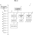
- FIG. 4 is a control block diagram showing the configuration of a control system 7 composed of a plurality of ECUs (Electronic Control Units) and mounted on the towing vehicle 11.
- the control system 7 includes an autonomous driving ECU 71, a drive ECU 72, a steering ECU 73, and a braking ECU 74.
- the ECUs 71 to 74 are connected to an in-vehicle network 70 such as a CAN (Controller Area Network) or an LIN (Local Interconnect Network), and can communicate bidirectionally.
- CAN Controller Area Network
- LIN Local Interconnect Network
- the ECUs 71 to 74 can acquire detection results from a plurality of sensors installed in various parts of the towing vehicle 11 via the in-vehicle network 70.
- the plurality of sensors includes: the hitch angle sensor 81 that detects the hitch angle between the towing vehicle 11 and the towed vehicle 12; wheel speed sensors 82 that detect the rotational speeds of the front wheels 21, 22 and the rear wheels 23, 24; a voltage sensor 83 that detects the voltage of the battery 31; a steering angle sensor 84 that detects the steering angle of the steering wheel 20; a steering torque sensor 85 that detects the steering torque applied to the steering wheel 20; an EPS temperature sensor 86 that detects the temperature of the electric power steering system 45, an accelerator pedal sensor 87 that detects the amount of depression of the accelerator pedal 111; a brake pedal sensor 88 that detects the amount of depression of the brake pedal 112; and a shift position sensor 89 that detects the position of the shift lever 115.
- the drive ECU 72 outputs a PWM (Pulse Width Modulation) signal to the inverter 32 according to the detection results from the accelerator pedal sensor 87 and the shift position sensor 89 to control the drive motor 30.
- the steering ECU 73 controls the electric power steering system 45 according to the detection results from the steering angle sensor 84 and the steering torque sensor 85.
- the braking ECU 74 controls the brake devices 51 to 54 according to the detection results from the brake pedal sensor 88 and the wheel speed sensors 82.
- the autonomous driving ECU 71 is an ECU that controls autonomous driving of the towing vehicle 11, and functions as a reverse control device when the combination vehicle 1 reverses.
- the autonomous driving ECU 71 can send commands to the drive ECU 72, the steering ECU 73, and the braking ECU 74 to perform various operations. Specifically, it is possible to send a driving force command signal to the drive ECU 72 and cause the drive motor 30 to generate a driving force according to the driving force command signal.
- the autonomous driving ECU 71 can send a steered angle command signal to the steering ECU 73 to steer the front wheels 21, 22 to an angle according to the steered angle command signal.
- the autonomous driving ECU 71 can send a braking force command signal to the braking ECU 74 to cause the brake devices 51 to 54 to generate a braking force according to the braking force command signal.
- the autonomous driving ECU 71 can communicate with the image processing device 60, and can acquire information on whether there is any obstacle perceived by the image processing device 60, and information on the position and size of the obstacle, if any.
- the autonomous driving ECU 71 can also acquire information indicating the operating state of the start button 117.
- autonomous driving ECU 71 starts towing reverse control for reversing the combination vehicle 1 by autonomous driving.
- autonomous driving for reversing the towing vehicle 11 will be referred to as autonomous reverse driving.
- autonomous driving means not only causing the towing vehicle 11 to travel with the driver of the towing vehicle 11 not operating any of the steering wheel 20, the accelerator pedal 111, and the brake pedal 112.
- autonomous driving also includes so-called driver assistance in which the driver does not operate the steering wheel 20 but operates the accelerator pedal 111 and the brake pedal 112.
- a person who performs an operation to start autonomous reverse driving of the combination vehicle 1 is not limited to the driver of the towing vehicle 11, and may be, for example, a passenger in the towing vehicle 11 or a person in the towed vehicle 12, or may be a person who is not in either the towing vehicle 11 or the towed vehicle 12.
- the person who performs the operation to start autonomous reverse driving will be referred to as the operator.
- the operator specifies either or both of the direction of travel and a target position during the autonomous reverse driving.
- the operator can specify either or both of the direction of travel and the target position by, for example, using the touch panel display 116.
- the operator may specify the direction of travel and the target position of the combination vehicle 1 by operating an operation device installed in the towing vehicle 11 or the towed vehicle 12 or by operating the operator's wireless information terminal.
- the plurality of towing reverse start conditions includes the following first to twelfth conditions.
- the autonomous driving ECU 71 starts the towing reverse control when all of the first to twelfth conditions are met.
- the first condition is that the speed of the towing vehicle 11 is equal to or less than a predetermined value.
- the autonomous driving ECU 71 can obtain the speed of the towing vehicle 11 based on, for example, the detection results from the wheel speed sensors 82.
- the predetermined value in the first condition is a value small enough that the first condition is satisfied only when the towing vehicle 11 is substantially at a stop. In other words, the first condition can also be said to be that the towing vehicle 11 is at a stop.
- the second condition is that the accelerator pedal 111 is not being depressed.
- the autonomous driving ECU 71 can determine that the second condition is satisfied when the amount of depression of the accelerator pedal 111 is equal to or less than a predetermined value based on the detection results from the accelerator pedal sensor 87.
- the predetermined value in the second condition is a value less than the amount of depression set as the play of the accelerator pedal 111.
- the play refers to a region in which the amount of depression of the accelerator pedal 111 is small, namely a region in which the operation of depressing the accelerator pedal 111 does not affect control of the drive motor 30.
- the third condition is that the towing vehicle 11 is being braked.
- the autonomous driving ECU 71 can determine that the third condition is satisfied when the amount of depression of the brake pedal 112 is equal to or greater than a predetermined value based on, for example, the detection results from the brake pedal sensor 88. This determination need not necessarily be made based on a brake (foot brake) that is activated when the brake pedal 112 is depressed. For example, it can be determined that the third condition is satisfied when the towing vehicle 11 is being braked by, for example, a parking brake.
- the fourth condition is that the steering torque is equal to or less than a predetermined value.
- the autonomous driving ECU 71 can determine whether the fourth condition is satisfied based on the detection results from the steering torque sensor 85.
- the predetermined value in the fourth condition is a value small enough that the fourth condition is satisfied only when the steering wheel 20 is not being steered. In other words, the fourth condition can be said to be that the steering wheel 20 is not being steered.
- the fifth condition is that the shift position of the shift lever 115 is in the reverse range.
- the autonomous driving ECU 71 can determine whether the fifth condition is satisfied based on the detection results from the shift position sensor 89.
- the sixth condition is that the drive ECU 72, the steering ECU 73, and the braking ECU 74 are operating normally.
- the autonomous driving ECU 71 can determine that the sixth condition is satisfied when communication with the drive ECU 72, the steering ECU 73, and the braking ECU 74 is normal, and when information obtained from the drive ECU 72, the steering ECU 73, and the braking ECU 74 does not include information indicating that an abnormality has occurred in any of the ECUs 72 to 74.
- the seventh condition is that there is no abnormality in any of devices to be controlled by the drive ECU 72, the steering ECU 73, and the braking ECU 74.
- the devices to be controlled by the drive ECU 72 are the drive motor 30 and the inverter 32.
- the device to be controlled by the steering ECU 73 is the electric power steering system 45.
- the devices to be controlled by the braking ECU 74 are the brake devices 51 to 54.
- the autonomous driving ECU 71 can determine whether the seventh condition is satisfied based on information obtained by, for example, communication with the drive ECU 72, the steering ECU 73, and the braking ECU 74. For example, the seventh condition is not satisfied when the information obtained from the steering ECU 73 includes information indicating overheating of the electric power steering system 45.
- the eighth condition is that the voltage of the battery 31 is within an appropriate range.
- the autonomous driving ECU 71 can determine whether the eighth condition is satisfied based on the detection results from the voltage sensor 83.
- the ninth condition is that the above sensors 81 to 89 are operating normally.
- the autonomous driving ECU 71 determines that the ninth condition is not satisfied when the detection results from any of the sensors 81 to 89 are not within a normal range.
- the steering angle sensor 84 is not an absolute encoder that can detect an absolute position of the steering angle, but is, for example, an incremental encoder that outputs a pulse signal
- the autonomous driving ECU 71 also determines that the ninth condition is not satisfied when offset adjustment of the neutral position of the steering wheel 20 is incomplete.
- the autonomous driving ECU 71 also determines that the ninth condition is not satisfied when offset adjustment of the hitch angle that is detected by the hitch angle sensor 81 is incomplete.
- the offset adjustment of the neutral position of the steering wheel 20 and the offset adjustment of the hitch angle can be made by, for example, setting the steering angle and the hitch angle when the combination vehicle 1 linearly travels a predetermined distance forward to zero.
- the autonomous driving ECU 71 also determines that the ninth condition is not satisfied when it is determined that the hitch angle is not being correctly detected by the hitch angle sensor 81.
- the ninth condition includes the hitch angle between the towing vehicle 11 and the towed vehicle 12 being correctly detected by the hitch angle sensor 81.
- Whether the hitch angle is being correctly detected by the hitch angle sensor 81 can be determined based on, for example, images captured by the rear camera 62, the left side camera 63, and the right side camera 64, namely by comparing these images with the detection value of the hitch angle sensor 81.
- the hitch angle detected by the hitch angle sensor 81 is 0°, but it is detected from the images from the rear camera 62, the left side camera 63, and the right side camera 64 that the towed vehicle 12 is tilted in the horizontal direction with respect to the towing vehicle 11, it is determined that the hitch angle is not being correctly detected by the hitch angle sensor 81.
- the tenth condition is that no obstacle that would hinder reversing is found in images from the front camera 61, the rear camera 62, the left side camera 63, and the right side camera 64.
- the autonomous driving ECU 71 determines that the tenth condition is satisfied when it determines based on the information obtained from the image processing device 60 that no obstacle that would hinder reversing is present around the towing vehicle 11 or the towed vehicle 12 in the direction of travel specified by the operator, or around the towing vehicle 11 or the towed vehicle 12 on a path to a target position specified by the operator.
- the autonomous driving ECU 71 determines that the tenth condition is not satisfied when it determines that such an obstacle is present.
- the eleventh condition is that the operator has performed an instruction operation to instruct to start autonomous driving while all of the first to tenth conditions are satisfied.
- This instruction operation can be performed by, for example, operating the start button 117 for the autonomous reverse driving as described above.
- an instruction operation to cause the autonomous driving ECU 71 to start the towing reverse control may be performed by operating the operation device installed in the towing vehicle 11 or the towed vehicle 12 or by operating the operator's wireless information terminal.
- the twelfth condition is that the towed vehicle 12 is connected to the towing vehicle 11.
- the autonomous driving ECU 71 can make this determination based on, for example, whether information on the hitch angle has been acquired from the hitch angle sensor 81.
- the autonomous driving ECU 71 may determine whether the towed vehicle 12 is connected to the towing vehicle 11 particularly from information obtained from the image processing device 60 based on images from the rear camera 62.
- the autonomous driving ECU 71 starts non-towing reverse control to reverse, by autonomous driving, the towing vehicle 11 to which the towed vehicle 12 is not connected.
- the autonomous driving ECU 71 reverses only the towing vehicle 11 by the non-towing reverse control.
- the autonomous driving ECU 71 starts the towing reverse control when all of the first to twelfth conditions are satisfied.
- the autonomous driving ECU 71 calculates a target value of the hitch angle for moving the combination vehicle 1 in the direction of travel or to the target position specified by the operator, sends a command to the steering ECU 73 so that the actual hitch angle matches this target value, and causes the steering device 4 to steer the left and right front wheels 21, 22.
- the towing vehicle 11 is being braked due to the third condition. Therefore, the combination vehicle 1 starts to reverse after the towing vehicle 11 is released from the braked state.
- the speed of the towing vehicle 11 during reversing may be controlled by the autonomous driving ECU 71, or may be adjusted by the driver operating the accelerator pedal 111 or the brake pedal 112.
- the autonomous driving ECU 71 stops the towing reverse control to bring the combination vehicle 1 to a stop.
- the autonomous driving ECU 71 also stops the towing reverse control when any of the following first to third stop conditions is satisfied.
- the first stop condition is that the brake pedal 112 is depressed with a force large enough to stop the towing vehicle 11.
- the towing reverse control is stopped when the amount of depression of the brake pedal 112 becomes larger than the predetermined value of the third condition. Accordingly, for example, if the driver of the towing vehicle 11 feels some kind of danger from the surrounding conditions, he or she can immediately stop the towing vehicle 11 by depressing the brake pedal 112 hard. However, when the towing vehicle 11 is located near the target position, the driver may depress the brake pedal 112 to adjust the speed. Therefore, the predetermined value of the amount of depression of the brake pedal 112 for stopping the towing reverse control is set to be greater than the predetermined value of the third condition.
- the autonomous driving ECU 71 can adjust the traveling speed according to the amount of depression of the brake pedal 112 during the autonomous reverse driving for moving the combination vehicle 1 toward the target position, and has a function to stop the autonomous reverse driving when the amount of depression of the brake pedal 112 becomes equal to or greater than the predetermined value.
- the autonomous driving ECU 71 sets the predetermined value of the amount of depression of the brake pedal 112 to a value greater than before the combination vehicle 1 reached near the target position.
- the second stop condition is that the operator has instructed to stop autonomous driving, or that the target position specified by the operator has been reached.
- the operator can instruct to stop autonomous driving by, for example, operating the start button 117 again.
- the operator may instruct to stop autonomous driving by operating the operation device installed in the towing vehicle 11 or the towed vehicle 12 or by operating the operator's wireless information terminal.
- the third stop condition is that the hitch angle between the towing vehicle 11 and the towed vehicle 12 has become equal to or greater than a predetermined value due to, for example, the towing vehicle 11 or the towed vehicle 12 slipping because of a cross wind, a slope of a road surface, etc.
- the predetermined value of the hitch angle is an angle large enough for a jackknife phenomenon to occur.
- the jackknife phenomenon refers to a phenomenon in which, even when the towing vehicle 11 reverses, the hitch angle only increases and the towed vehicle 12 does not reverse. In such a case, the driver manually moves the towing vehicle 11 forward to reduce the hitch angle, and then the operator starts the towing reverse control by the autonomous driving ECU 71 again.
- the autonomous driving ECU 71 After starting the non-towing reverse control of the towing vehicle 11 to which the towed vehicle 12 is not connected, the autonomous driving ECU 71 stops the non-towing reverse control when any of the fourth to tenth conditions becomes unsatisfied or the first stop condition or the second stop condition is satisfied.
- FIG. 5 is a flowchart showing an example of a process that is performed by the autonomous driving ECU 71.
- the autonomous driving ECU 71 repeatedly performs the process of this flowchart at predetermined control cycles.
- the autonomous driving ECU 71 determines whether the towing reverse control is being performed (step S1). When the towing reverse control is being performed, the autonomous driving ECU 71 determines whether the fourth to tenth conditions are satisfied (step S2). When the result of the determination in step S2 is Yes, the autonomous driving ECU 71 determines whether all of the first to third stop conditions are unsatisfied (step S3). When the result of this determination is Yes, the autonomous driving ECU 71 continues the towing reverse control (step S4). On the other hand, when the result of the determination in step S2 or step S3 is No, the autonomous driving ECU 71 stops the towing reverse control (step S5).
- step S6 determines whether the non-towing reverse control is being performed.
- step S7 determines whether the fourth to tenth conditions are satisfied.
- step S8 determines whether both the first stop condition and the second stop condition are unsatisfied.
- step S9 the autonomous driving ECU 71 stops the non-towing reverse control.
- step S11 determines whether the first to eleventh conditions are satisfied.
- step S12 determines whether the twelfth condition is satisfied.
- step S13 the autonomous driving ECU 71 starts the towing reverse control.
- step S14 the autonomous driving ECU 71 starts the non-towing reverse control.
- autonomous reverse driving of the combination vehicle 1 can be stably performed by starting reversing the combination vehicle 1 by autonomous driving only when all of the first to twelfth conditions are satisfied.
- the first embodiment described above illustrates a case where the operator performs an instruction operation to instruct to start the autonomous reverse driving by operating the start button 117, by operating the operation device installed in the towing vehicle 11 or the towed vehicle 12, or by operating the operator's wireless information terminal.
- the autonomous driving ECU 71 starts the autonomous reverse driving in response to an instruction operation that the driver of the towing vehicle 11 performs by operating the accelerator pedal 111. More specifically, when the amount of depression of the accelerator pedal 111 is equal to or greater than a predetermined value based on the detection results from the accelerator pedal sensor 87, the autonomous driving ECU 71 starts the autonomous reverse driving.
- the conditions for starting the towing reverse control or the non-towing reverse control include that the accelerator pedal 111 is not being depressed (second condition). However, this condition is excluded in the present embodiment.
- essential conditions for starting the towing reverse control or the non-towing reverse control include that the towing vehicle 11 is in an autonomous driving mode.
- the eleventh condition described above is that the accelerator pedal 111 of the towing vehicle 11 is operated while all of the first condition and the third to tenth conditions are satisfied and the towing vehicle 11 is in the autonomous driving mode.
- Determination as to whether the towing vehicle 11 is in the autonomous driving mode can be made based on, for example, the setting state of a switch for switching between a manual driving mode and the autonomous driving mode. It may be determined that the towing vehicle 11 is in the autonomous driving mode based on whether a target position or a direction of travel has been set by the operator.
- the operational burden on the driver can be reduced when, for example, adjusting the vehicle speed during reversing by the amount of depression of the accelerator pedal 111 by the driver.
Landscapes
- Engineering & Computer Science (AREA)
- Transportation (AREA)
- Mechanical Engineering (AREA)
- Chemical & Material Sciences (AREA)
- Combustion & Propulsion (AREA)
- Automation & Control Theory (AREA)
- Human Computer Interaction (AREA)
- Control Of Driving Devices And Active Controlling Of Vehicle (AREA)
- Steering Control In Accordance With Driving Conditions (AREA)
Abstract
Description
- The present invention relates to reverse control devices for combination vehicles that are used in combination vehicles in which a towed vehicle is towed by a towing vehicle and that control the towed vehicle when the combination vehicle reverses.
- A combination vehicle in which a towed vehicle is towed by a towing vehicle is relatively easy to maneuver when moving it forward because the towed vehicle follows the towing vehicle. However, especially in the case where a driver of a towing vehicle is not proficient in driving a combination vehicle, a combination vehicle is difficult to maneuver when reversing it, such as when parking it in a parking space, because a towed vehicle does not always move in a direction according to the steering angle of the towing vehicle. Therefore, devices and methods have been proposed that assist in maneuvering a combination vehicle when reversing it. For example, an autonomous or semi-autonomous driving system described in PTL 1 allows an operator inside a vehicle cabin to give operation commands to the system with his or her voice by saying commands such as "back up 10 feet," "stop," and "turn right 90 degrees."
- PTL 1:
US Patent No. 9688306 - A reverse control device that can automatically reverse a combination vehicle may not be able to appropriately guide the combination vehicle to a destination point by autonomous driving, depending on the state of a towing vehicle at the start of reversing the combination vehicle. Therefore, an object of the present invention is to provide a reverse control device that starts reversing a combination vehicle by autonomous driving only when conditions for appropriately performing the autonomous driving are satisfied, and that can stably reverse the combination vehicle by the autonomous driving.
- In order to achieve the above object, the present invention provides a reverse control device for a combination vehicle that is mounted on a towing vehicle of the combination vehicle in which a towed vehicle is connected to the towing vehicle including a steering device, and that controls the towing vehicle during autonomous reverse driving for reversing the combination vehicle by autonomous driving. The reverse control device starts the autonomous reverse driving when all of start conditions are satisfied, the start conditions including that a speed of the towing vehicle is equal to or less than a predetermined value and that steering torque of the towing vehicle is equal to or less than a predetermined value.
- The reverse control device according to the present invention starts reversing a combination vehicle by autonomous driving only when conditions for appropriately performing the autonomous driving are satisfied, and can stably reverse the combination vehicle by the autonomous driving.
-
- (
FIG. 1) FIG. 1 is an overhead view showing a combination vehicle according to a first embodiment of the present invention. - (
FIG. 2) FIG. 2 is a schematic configuration diagram showing a configuration example of a hitch angle sensor. - (
FIG. 3) FIG. 3 is a schematic configuration diagram showing a configuration example of a towing vehicle. - (
FIG. 4) FIG. 4 is a control block diagram showing the configuration of a control system composed of a plurality of ECUs. - (
FIG. 5) FIG. 5 is a flowchart showing an example of a process that is performed by an autonomous driving ECU. - A first embodiment of the present invention will be described with reference to the drawings. The embodiments described below are shown as specific examples suitable for carrying out the present invention, and part of the embodiments specifically illustrates various technical matters that are technically preferable. However, the technical scope of the present invention is not limited to these specific forms.
-
FIG. 1 is an overhead view showing a combination vehicle 1 according to the present embodiment. The combination vehicle 1 includes atowing vehicle 11 and atowed vehicle 12. When the combination vehicle 1 moves forward, thetowed vehicle 12 is towed by thetowing vehicle 11. Thetowing vehicle 11 and thetowed vehicle 12 are connected by a towing-side connecting member 13 on thetowing vehicle 11 side and a towed-side connecting member 14 on thetowed vehicle 12 side.FIG. 1 shows a case where thetowed vehicle 12 is a box-shaped camper as an example. However, thetowed vehicle 12 is not limited to this, and may be, for example, a boat trailer loaded with a boat, or a cargo trailer. - The towing-
side connecting member 13 is provided with aspherical hitch ball 131. The towed-side connecting member 14 includes: acoupler 141 that covers thehitch ball 131; alatch mechanism 142 that retains thecoupler 141 on thehitch ball 131 by an operation of alever 142a; a rod-shaped tongue 143 with thecoupler 141 fixed to its distal end. The towed-side connecting member 14 is swingable about ahitch point 131a that is the center point of thehitch ball 131. - In
FIG. 1 , each of acenter line 11a of thetowing vehicle 11 in the front-rear direction of thetowing vehicle 11 and acenter line 12a of thetowed vehicle 12 in the front-rear direction of thetowed vehicle 12 is shown by a long dashed short dashed line. When the combination vehicle 1 is viewed from above, thecenter line 11a of thetowing vehicle 11 and thecenter line 12a of thetowed vehicle 12 in the front-rear direction of thetowed vehicle 12 intersect at thehitch point 131a. The angle θh between thecenter line 11a of thetowing vehicle 11 and thecenter line 12a of thetowed vehicle 12 in the front-rear direction of thetowed vehicle 12 is a hitch angle that indicates a tilt angle of thetowed vehicle 12 with respect to thetowing vehicle 11. The hitch angle is detected by a hitch angle sensor. -
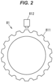
FIG. 2 is a schematic configuration diagram showing a configuration example of ahitch angle sensor 81. Thehitch angle sensor 81 includes a gear-shapedmagnetic element 811 fixed to thecoupler 141, and amagnetic sensor 812 attached to the towing-side connecting member 13. Themagnetic sensor 812 faces the outer periphery of themagnetic element 811. The strength of a magnetic field that is detected by themagnetic sensor 812 changes as themagnetic element 811 rotates with respect to themagnetic sensor 812. Therefore, the hitch angle can be detected based on the change in strength of the magnetic field. -
FIG. 3 is a schematic configuration diagram showing a configuration example of thetowing vehicle 11. Thetowing vehicle 11 includes left and rightfront wheels rear wheels towing vehicle 11 has an autonomous driving function that enables autonomous driving for automatically steering the left and rightfront wheels towing vehicle 11 is a battery electric vehicle using, as its driving source, adrive motor 30 that is supplied with a current and generates a driving force. Thetowing vehicle 11 is equipped with abattery 31 and aninverter 32. A direct current output from thebattery 31 is converted to an alternating current by theinverter 32 and supplied to thedrive motor 30. When a driver drives thetowing vehicle 11, the magnitude of the current that is supplied to thedrive motor 30 changes according to the amount of depression of anaccelerator pedal 111. - The
drive motor 30 is an interior permanent magnet (IPM) synchronous motor including a stator that generates a rotating magnetic field by the alternating current supplied from theinverter 32, and a rotor that rotates with respect to the stator, with a plurality of permanent magnets embedded in the rotor. However, electric motors with other configurations may be used as thedrive motor 30. The driving source of thetowing vehicle 11 may be an engine that is an internal combustion engine, or may be a hybrid system that is a combination of an engine and an electric motor. - Torque output from the
drive motor 30 is transferred from apinion gear 301 fixed to an outputrotary shaft 300 of thedrive motor 30 to aring gear 302, and is input to adifferential unit 33. Thedifferential unit 33 includes: adifferential case 331 to which thering gear 302 is fixed; apinion gear shaft 332 fixed to thedifferential case 331; a plurality ofpinion gears 333 supported by thepinion gear shaft 332; and a pair ofside gears pinion gears 333 with their gear axes perpendicular to those of the plurality ofpinion gears 333. - A
left drive shaft 34 is connected to oneside gear 334 of thedifferential unit 33, and aright drive shaft 35 is connected to theother side gear 335. Torque input to thedifferential unit 33 is distributed to the leftfront wheel 21 and the rightfront wheel 22 via thedrive shafts - The left and right
front wheels steering device 4. Thesteering device 4 includes: asteering wheel 40 that is steered by the driver of thetowing vehicle 11; asteering shaft 41 connected to thesteering wheel 40; arack shaft 42 that moves back and forth in the vehicle width direction as thesteering shaft 41 rotates;tie rods 44 swingably connected to both ends of therack shaft 42 viaball joints 43; and an electric power steering (EPS)system 45. During manual driving when the driver steers thesteering wheel 40, the electricpower steering system 45 functions as a steering assist device that generates a steering assist force to assist a steering operation of thesteering wheel 40. During autonomous driving, the electricpower steering system 45 functions as an actuator that moves therack shaft 42 to steer the left and rightfront wheels - The
front wheels rear wheels metal wheels rubber tires Brake devices 51 to 54 are provided corresponding to thefront wheels rear wheels brake devices 51 to 54 generate braking forces of a strength according to the amount of depression of abrake pedal 112. - The towing
vehicle 11 is equipped with a plurality of cameras that captures an image of the surroundings of the combination vehicle 1. In the present embodiment, the plurality of cameras includes: afront camera 61 that captures an image of the area in front of the towingvehicle 11; arear camera 62 that captures an image of the area behind the towingvehicle 11; aleft side camera 63 that captures an image of the area to the left of the towingvehicle 11; and aright side camera 64 that captures an image of the area to the right of the towingvehicle 11. Thefront camera 61 is installed at the front end of the towingvehicle 11, and therear camera 62 is installed at the rear end of the towingvehicle 11. Theleft side camera 63 and theright side camera 64 are installed on left and right side mirrors 113, 114, respectively. - Image information of images captured by the
front camera 61, therear camera 62, theleft side camera 63, and theright side camera 64 are sent to animage processing device 60. Theimage processing device 60 analyzes the image information from each of thesecameras 61 to 64 to grasp the situation around the combination vehicle 1 and perceives an obstacle, if any. The towedvehicle 12 may also be equipped with a camera, and theimage processing device 60 may also use image information from this camera to perceive an obstacle around the combination vehicle 1. - The towing
vehicle 11 is also provided with ashift lever 115. The driver can shift theshift lever 115 to a parking range in which the towingvehicle 11 is not allowed to move, a reverse range for reverse traveling, a neutral range, and a drive range for forward traveling. - A touch panel display (TPD) 116 is installed in the towing
vehicle 11 at a position where the driver can operate it. Thetouch panel display 116 is used as a display for a car navigation system, and is also used to display images of the surroundings of the combination vehicle 1 created by theimage processing device 60. For example, theimage processing device 60 combines overhead images of the surroundings of the combination vehicle 1 from the image information obtained from each of thecameras 61 to 64, and displays the resultant image on thetouch panel display 116. - The towing
vehicle 11 is also provided with astart button 117 that is operated by the driver. Thestart button 117 is a button for starting reversing the combination vehicle 1 under autonomous driving. Thestart button 117 is, for example, a push button switch, but is not limited to this. The start button may be a virtual button displayed on thetouch panel display 116. -
FIG. 4 is a control block diagram showing the configuration of acontrol system 7 composed of a plurality of ECUs (Electronic Control Units) and mounted on the towingvehicle 11. Thecontrol system 7 includes anautonomous driving ECU 71, adrive ECU 72, asteering ECU 73, and abraking ECU 74. TheECUs 71 to 74 are connected to an in-vehicle network 70 such as a CAN (Controller Area Network) or an LIN (Local Interconnect Network), and can communicate bidirectionally. - The
ECUs 71 to 74 can acquire detection results from a plurality of sensors installed in various parts of the towingvehicle 11 via the in-vehicle network 70. The plurality of sensors includes: thehitch angle sensor 81 that detects the hitch angle between the towingvehicle 11 and the towedvehicle 12;wheel speed sensors 82 that detect the rotational speeds of thefront wheels rear wheels voltage sensor 83 that detects the voltage of thebattery 31; asteering angle sensor 84 that detects the steering angle of the steering wheel 20; asteering torque sensor 85 that detects the steering torque applied to the steering wheel 20; anEPS temperature sensor 86 that detects the temperature of the electricpower steering system 45, anaccelerator pedal sensor 87 that detects the amount of depression of theaccelerator pedal 111; abrake pedal sensor 88 that detects the amount of depression of thebrake pedal 112; and ashift position sensor 89 that detects the position of theshift lever 115. - During manual driving when the driver maneuvers the towing
vehicle 11, thedrive ECU 72 outputs a PWM (Pulse Width Modulation) signal to theinverter 32 according to the detection results from theaccelerator pedal sensor 87 and theshift position sensor 89 to control thedrive motor 30. The steeringECU 73 controls the electricpower steering system 45 according to the detection results from thesteering angle sensor 84 and thesteering torque sensor 85. Thebraking ECU 74 controls thebrake devices 51 to 54 according to the detection results from thebrake pedal sensor 88 and thewheel speed sensors 82. - The
autonomous driving ECU 71 is an ECU that controls autonomous driving of the towingvehicle 11, and functions as a reverse control device when the combination vehicle 1 reverses. During autonomous driving, theautonomous driving ECU 71 can send commands to thedrive ECU 72, the steeringECU 73, and thebraking ECU 74 to perform various operations. Specifically, it is possible to send a driving force command signal to thedrive ECU 72 and cause thedrive motor 30 to generate a driving force according to the driving force command signal. Theautonomous driving ECU 71 can send a steered angle command signal to thesteering ECU 73 to steer thefront wheels autonomous driving ECU 71 can send a braking force command signal to thebraking ECU 74 to cause thebrake devices 51 to 54 to generate a braking force according to the braking force command signal. - The
autonomous driving ECU 71 can communicate with theimage processing device 60, and can acquire information on whether there is any obstacle perceived by theimage processing device 60, and information on the position and size of the obstacle, if any. Theautonomous driving ECU 71 can also acquire information indicating the operating state of thestart button 117. - When all of a plurality of towing reverse start conditions are satisfied, the
autonomous driving ECU 71 starts towing reverse control for reversing the combination vehicle 1 by autonomous driving. Hereinafter, autonomous driving for reversing the towingvehicle 11 will be referred to as autonomous reverse driving. As used herein, autonomous driving means not only causing the towingvehicle 11 to travel with the driver of the towingvehicle 11 not operating any of the steering wheel 20, theaccelerator pedal 111, and thebrake pedal 112. Autonomous driving also includes so-called driver assistance in which the driver does not operate the steering wheel 20 but operates theaccelerator pedal 111 and thebrake pedal 112. - A person who performs an operation to start autonomous reverse driving of the combination vehicle 1 is not limited to the driver of the towing
vehicle 11, and may be, for example, a passenger in the towingvehicle 11 or a person in the towedvehicle 12, or may be a person who is not in either the towingvehicle 11 or the towedvehicle 12. Hereinafter, the person who performs the operation to start autonomous reverse driving will be referred to as the operator. - The operator specifies either or both of the direction of travel and a target position during the autonomous reverse driving. The operator can specify either or both of the direction of travel and the target position by, for example, using the
touch panel display 116. The operator may specify the direction of travel and the target position of the combination vehicle 1 by operating an operation device installed in the towingvehicle 11 or the towedvehicle 12 or by operating the operator's wireless information terminal. - The plurality of towing reverse start conditions includes the following first to twelfth conditions. The
autonomous driving ECU 71 starts the towing reverse control when all of the first to twelfth conditions are met. - The first condition is that the speed of the towing
vehicle 11 is equal to or less than a predetermined value. Theautonomous driving ECU 71 can obtain the speed of the towingvehicle 11 based on, for example, the detection results from thewheel speed sensors 82. The predetermined value in the first condition is a value small enough that the first condition is satisfied only when the towingvehicle 11 is substantially at a stop. In other words, the first condition can also be said to be that the towingvehicle 11 is at a stop. - The second condition is that the
accelerator pedal 111 is not being depressed. Theautonomous driving ECU 71 can determine that the second condition is satisfied when the amount of depression of theaccelerator pedal 111 is equal to or less than a predetermined value based on the detection results from theaccelerator pedal sensor 87. The predetermined value in the second condition is a value less than the amount of depression set as the play of theaccelerator pedal 111. As used herein, the play refers to a region in which the amount of depression of theaccelerator pedal 111 is small, namely a region in which the operation of depressing theaccelerator pedal 111 does not affect control of thedrive motor 30. - The third condition is that the towing
vehicle 11 is being braked. Theautonomous driving ECU 71 can determine that the third condition is satisfied when the amount of depression of thebrake pedal 112 is equal to or greater than a predetermined value based on, for example, the detection results from thebrake pedal sensor 88. This determination need not necessarily be made based on a brake (foot brake) that is activated when thebrake pedal 112 is depressed. For example, it can be determined that the third condition is satisfied when the towingvehicle 11 is being braked by, for example, a parking brake. - The fourth condition is that the steering torque is equal to or less than a predetermined value. The
autonomous driving ECU 71 can determine whether the fourth condition is satisfied based on the detection results from thesteering torque sensor 85. The predetermined value in the fourth condition is a value small enough that the fourth condition is satisfied only when the steering wheel 20 is not being steered. In other words, the fourth condition can be said to be that the steering wheel 20 is not being steered. - The fifth condition is that the shift position of the
shift lever 115 is in the reverse range. Theautonomous driving ECU 71 can determine whether the fifth condition is satisfied based on the detection results from theshift position sensor 89. - The sixth condition is that the
drive ECU 72, the steeringECU 73, and thebraking ECU 74 are operating normally. Theautonomous driving ECU 71 can determine that the sixth condition is satisfied when communication with thedrive ECU 72, the steeringECU 73, and thebraking ECU 74 is normal, and when information obtained from thedrive ECU 72, the steeringECU 73, and thebraking ECU 74 does not include information indicating that an abnormality has occurred in any of theECUs 72 to 74. - The seventh condition is that there is no abnormality in any of devices to be controlled by the
drive ECU 72, the steeringECU 73, and thebraking ECU 74. The devices to be controlled by thedrive ECU 72 are thedrive motor 30 and theinverter 32. The device to be controlled by the steeringECU 73 is the electricpower steering system 45. The devices to be controlled by the brakingECU 74 are thebrake devices 51 to 54. Theautonomous driving ECU 71 can determine whether the seventh condition is satisfied based on information obtained by, for example, communication with thedrive ECU 72, the steeringECU 73, and thebraking ECU 74. For example, the seventh condition is not satisfied when the information obtained from the steeringECU 73 includes information indicating overheating of the electricpower steering system 45. - The eighth condition is that the voltage of the
battery 31 is within an appropriate range. Theautonomous driving ECU 71 can determine whether the eighth condition is satisfied based on the detection results from thevoltage sensor 83. - The ninth condition is that the
above sensors 81 to 89 are operating normally. For example, the autonomous drivingECU 71 determines that the ninth condition is not satisfied when the detection results from any of thesensors 81 to 89 are not within a normal range. When thesteering angle sensor 84 is not an absolute encoder that can detect an absolute position of the steering angle, but is, for example, an incremental encoder that outputs a pulse signal, theautonomous driving ECU 71 also determines that the ninth condition is not satisfied when offset adjustment of the neutral position of the steering wheel 20 is incomplete. Theautonomous driving ECU 71 also determines that the ninth condition is not satisfied when offset adjustment of the hitch angle that is detected by thehitch angle sensor 81 is incomplete. The offset adjustment of the neutral position of the steering wheel 20 and the offset adjustment of the hitch angle can be made by, for example, setting the steering angle and the hitch angle when the combination vehicle 1 linearly travels a predetermined distance forward to zero. - The
autonomous driving ECU 71 also determines that the ninth condition is not satisfied when it is determined that the hitch angle is not being correctly detected by thehitch angle sensor 81. In other words, the ninth condition includes the hitch angle between the towingvehicle 11 and the towedvehicle 12 being correctly detected by thehitch angle sensor 81. Whether the hitch angle is being correctly detected by thehitch angle sensor 81 can be determined based on, for example, images captured by therear camera 62, theleft side camera 63, and theright side camera 64, namely by comparing these images with the detection value of thehitch angle sensor 81. Specifically, for example, when the hitch angle detected by thehitch angle sensor 81 is 0°, but it is detected from the images from therear camera 62, theleft side camera 63, and theright side camera 64 that the towedvehicle 12 is tilted in the horizontal direction with respect to the towingvehicle 11, it is determined that the hitch angle is not being correctly detected by thehitch angle sensor 81. - The tenth condition is that no obstacle that would hinder reversing is found in images from the
front camera 61, therear camera 62, theleft side camera 63, and theright side camera 64. Theautonomous driving ECU 71 determines that the tenth condition is satisfied when it determines based on the information obtained from theimage processing device 60 that no obstacle that would hinder reversing is present around the towingvehicle 11 or the towedvehicle 12 in the direction of travel specified by the operator, or around the towingvehicle 11 or the towedvehicle 12 on a path to a target position specified by the operator. Theautonomous driving ECU 71 determines that the tenth condition is not satisfied when it determines that such an obstacle is present. - The eleventh condition is that the operator has performed an instruction operation to instruct to start autonomous driving while all of the first to tenth conditions are satisfied. This instruction operation can be performed by, for example, operating the
start button 117 for the autonomous reverse driving as described above. However, an instruction operation to cause theautonomous driving ECU 71 to start the towing reverse control may be performed by operating the operation device installed in the towingvehicle 11 or the towedvehicle 12 or by operating the operator's wireless information terminal. - The twelfth condition is that the towed
vehicle 12 is connected to the towingvehicle 11. Theautonomous driving ECU 71 can make this determination based on, for example, whether information on the hitch angle has been acquired from thehitch angle sensor 81. Theautonomous driving ECU 71 may determine whether the towedvehicle 12 is connected to the towingvehicle 11 particularly from information obtained from theimage processing device 60 based on images from therear camera 62. - When the first to eleventh conditions are satisfied but the twelfth condition is not satisfied, the
autonomous driving ECU 71 starts non-towing reverse control to reverse, by autonomous driving, the towingvehicle 11 to which the towedvehicle 12 is not connected. In other words, when the towedvehicle 12 is not connected to the towingvehicle 11 at the time the instruction operation of the eleventh condition is performed, theautonomous driving ECU 71 reverses only the towingvehicle 11 by the non-towing reverse control. - The
autonomous driving ECU 71 starts the towing reverse control when all of the first to twelfth conditions are satisfied. During the towing reverse control, the autonomous drivingECU 71 calculates a target value of the hitch angle for moving the combination vehicle 1 in the direction of travel or to the target position specified by the operator, sends a command to thesteering ECU 73 so that the actual hitch angle matches this target value, and causes thesteering device 4 to steer the left and rightfront wheels vehicle 11 is being braked due to the third condition. Therefore, the combination vehicle 1 starts to reverse after the towingvehicle 11 is released from the braked state. The speed of the towingvehicle 11 during reversing may be controlled by theautonomous driving ECU 71, or may be adjusted by the driver operating theaccelerator pedal 111 or thebrake pedal 112. - When any of the fourth to tenth conditions becomes unsatisfied after the towing reverse control is started, the
autonomous driving ECU 71 stops the towing reverse control to bring the combination vehicle 1 to a stop. Theautonomous driving ECU 71 also stops the towing reverse control when any of the following first to third stop conditions is satisfied. - The first stop condition is that the
brake pedal 112 is depressed with a force large enough to stop the towingvehicle 11. Specifically, for example, the towing reverse control is stopped when the amount of depression of thebrake pedal 112 becomes larger than the predetermined value of the third condition. Accordingly, for example, if the driver of the towingvehicle 11 feels some kind of danger from the surrounding conditions, he or she can immediately stop the towingvehicle 11 by depressing thebrake pedal 112 hard. However, when the towingvehicle 11 is located near the target position, the driver may depress thebrake pedal 112 to adjust the speed. Therefore, the predetermined value of the amount of depression of thebrake pedal 112 for stopping the towing reverse control is set to be greater than the predetermined value of the third condition. - In other words, the
autonomous driving ECU 71 can adjust the traveling speed according to the amount of depression of thebrake pedal 112 during the autonomous reverse driving for moving the combination vehicle 1 toward the target position, and has a function to stop the autonomous reverse driving when the amount of depression of thebrake pedal 112 becomes equal to or greater than the predetermined value. When the combination vehicle 1 has reached near the target position, theautonomous driving ECU 71 sets the predetermined value of the amount of depression of thebrake pedal 112 to a value greater than before the combination vehicle 1 reached near the target position. - The second stop condition is that the operator has instructed to stop autonomous driving, or that the target position specified by the operator has been reached. The operator can instruct to stop autonomous driving by, for example, operating the
start button 117 again. The operator may instruct to stop autonomous driving by operating the operation device installed in the towingvehicle 11 or the towedvehicle 12 or by operating the operator's wireless information terminal. - The third stop condition is that the hitch angle between the towing
vehicle 11 and the towedvehicle 12 has become equal to or greater than a predetermined value due to, for example, the towingvehicle 11 or the towedvehicle 12 slipping because of a cross wind, a slope of a road surface, etc. The predetermined value of the hitch angle is an angle large enough for a jackknife phenomenon to occur. The jackknife phenomenon refers to a phenomenon in which, even when the towingvehicle 11 reverses, the hitch angle only increases and the towedvehicle 12 does not reverse. In such a case, the driver manually moves the towingvehicle 11 forward to reduce the hitch angle, and then the operator starts the towing reverse control by the autonomous drivingECU 71 again. - After starting the non-towing reverse control of the towing
vehicle 11 to which the towedvehicle 12 is not connected, theautonomous driving ECU 71 stops the non-towing reverse control when any of the fourth to tenth conditions becomes unsatisfied or the first stop condition or the second stop condition is satisfied. -
FIG. 5 is a flowchart showing an example of a process that is performed by the autonomous drivingECU 71. Theautonomous driving ECU 71 repeatedly performs the process of this flowchart at predetermined control cycles. - The
autonomous driving ECU 71 determines whether the towing reverse control is being performed (step S1). When the towing reverse control is being performed, the autonomous drivingECU 71 determines whether the fourth to tenth conditions are satisfied (step S2). When the result of the determination in step S2 is Yes, the autonomous drivingECU 71 determines whether all of the first to third stop conditions are unsatisfied (step S3). When the result of this determination is Yes, the autonomous drivingECU 71 continues the towing reverse control (step S4). On the other hand, when the result of the determination in step S2 or step S3 is No, theautonomous driving ECU 71 stops the towing reverse control (step S5). - When the result of the determination in step S1 is No, the autonomous driving
ECU 71 determines whether the non-towing reverse control is being performed (step S6). When the non-towing reverse control is being performed, the autonomous drivingECU 71 determines whether the fourth to tenth conditions are satisfied (step S7). When the result of the determination in step S7 is Yes, the autonomous drivingECU 71 determines whether both the first stop condition and the second stop condition are unsatisfied (step S8). When the result of this determination is Yes, the autonomous drivingECU 71 continues the non-towing reverse control (step S9). On the other hand, when the result of the determination in step S7 or step S8 is No, theautonomous driving ECU 71 stops the non-towing reverse control (step S10). - When the result of the determination in step S6 is No, the autonomous driving
ECU 71 determines whether the first to eleventh conditions are satisfied (step S11). When the result of this determination is Yes, the autonomous drivingECU 71 determines whether the twelfth condition is satisfied (step S12). When the result of the determination in step S12 is Yes, theautonomous driving ECU 71 starts the towing reverse control (step S13). When the result of the determination in step S12 is No, theautonomous driving ECU 71 starts the non-towing reverse control (step S14). On the other hand, when the result of the determination in step S11 is No, the process of the flowchart shown inFIG. 5 ends. - According to the first embodiment described above, autonomous reverse driving of the combination vehicle 1 can be stably performed by starting reversing the combination vehicle 1 by autonomous driving only when all of the first to twelfth conditions are satisfied.
- Next, a second embodiment of the present invention will be described. The first embodiment described above illustrates a case where the operator performs an instruction operation to instruct to start the autonomous reverse driving by operating the
start button 117, by operating the operation device installed in the towingvehicle 11 or the towedvehicle 12, or by operating the operator's wireless information terminal. In the present embodiment, theautonomous driving ECU 71 starts the autonomous reverse driving in response to an instruction operation that the driver of the towingvehicle 11 performs by operating theaccelerator pedal 111. More specifically, when the amount of depression of theaccelerator pedal 111 is equal to or greater than a predetermined value based on the detection results from theaccelerator pedal sensor 87, theautonomous driving ECU 71 starts the autonomous reverse driving. - In the first embodiment described above, the conditions for starting the towing reverse control or the non-towing reverse control include that the
accelerator pedal 111 is not being depressed (second condition). However, this condition is excluded in the present embodiment. In the present embodiment, in order to clearly distinguish from maneuvering during manual driving (non-autonomous driving) by the driver, essential conditions for starting the towing reverse control or the non-towing reverse control include that the towingvehicle 11 is in an autonomous driving mode. In other words, in the present embodiment, the eleventh condition described above is that theaccelerator pedal 111 of the towingvehicle 11 is operated while all of the first condition and the third to tenth conditions are satisfied and the towingvehicle 11 is in the autonomous driving mode. - Determination as to whether the towing
vehicle 11 is in the autonomous driving mode can be made based on, for example, the setting state of a switch for switching between a manual driving mode and the autonomous driving mode. It may be determined that the towingvehicle 11 is in the autonomous driving mode based on whether a target position or a direction of travel has been set by the operator. - According to the second embodiment, there is no need to operate the
start button 117 when starting reversing by autonomous driving. Therefore, in addition to the effects of the first embodiment described above, the operational burden on the driver can be reduced when, for example, adjusting the vehicle speed during reversing by the amount of depression of theaccelerator pedal 111 by the driver. - Although the present invention has been described above based on the first and second embodiments, these embodiments are not intended to limit the invention according to the claims. It should be noted that not all of the combinations of the features described in the embodiments are essential as means for solving the problem of the invention. The present invention may be modified as appropriate by omitting part of the configurations or adding or replacing configurations without departing from the spirit and scope of the present invention.
-
- 1 COMBINATION VEHICLE
- 4 STEERING DEVICE
- 11 TOWING VEHICLE
- 12 TOWED VEHICLE
- 45 ELECTRIC POWER STEERING SYSTEM
- 61 FRONT CAMERA
- 62 REAR CAMERA
- 63 LEFT SIDE CAMERA
- 64 RIGHT SIDE CAMERA
- 71 AUTONOMOUS DRIVING ECU (REVERSE CONTROL DEVICE)
- 81 HITCH ANGLE SENSOR
- 111 ACCELERATOR PEDAL
- 112 BRAKE PEDAL
Claims (11)
- A reverse control device for a combination vehicle that is mounted on a towing vehicle of the combination vehicle in which a towed vehicle is connected to the towing vehicle including a steering device, and that controls the towing vehicle during autonomous reverse driving for reversing the combination vehicle by autonomous driving, wherein the reverse control device starts the autonomous reverse driving when all of start conditions are satisfied, the start conditions including that a speed of the towing vehicle is equal to or less than a predetermined value and that steering torque of the towing vehicle is equal to or less than a predetermined value.
- The reverse control device for the combination vehicle according to claim 1, wherein the start conditions include that an operator has performed an instruction operation to instruct to start the autonomous reverse driving while the speed of the towing vehicle is equal to or less than the predetermined value and the steering torque of the towing vehicle is equal to or less than the predetermined value.
- The reverse control device for the combination vehicle according to claim 2, wherein the instruction operation is operating a start button for the autonomous reverse driving.
- The reverse control device for the combination vehicle according to claim 2, wherein the instruction operation is operating an accelerator pedal of the towing vehicle.
- The reverse control device for the combination vehicle according to claim 2, wherein in a case where the towed vehicle is not connected to the towing vehicle when the instruction operation is performed, the reverse control device reverses only the towing vehicle by the autonomous driving.
- The reverse control device for the combination vehicle according to claim 1, wherein the start conditions include that no obstacle that hinders reversing of the combination vehicle is found in an image from a camera that captures surroundings of the combination vehicle.
- The reverse control device for the combination vehicle according to claim 1, wherein the start conditions include that a hitch angle between the towing vehicle and the towed vehicle is being correctly detected by a hitch angle sensor.
- The reverse control device for the combination vehicle according to claim 7, wherein the reverse control device determines whether the hitch angle is being correctly detected by the hitch angle sensor, based on an image from a camera that captures surroundings of the combination vehicle.
- The reverse control device for the combination vehicle according to claim 1, wherein the reverse control device stops the autonomous reverse driving when a hitch angle between the towing vehicle and the towed vehicle becomes equal to or greater than a predetermined value.
- The reverse control device for the combination vehicle according to claim 1, wherein the reverse control device is able to adjust a traveling speed according to an amount of depression of a brake pedal during the autonomous reverse driving for moving the combination vehicle toward a target position, and has a function to stop the autonomous reverse driving when the amount of depression of the brake pedal becomes equal to or greater than a predetermined value.
- The reverse control device for the combination vehicle according to claim 10, wherein when the combination vehicle has reached near the target position, the reverse control device sets the predetermined value of the amount of depression to a value greater than before the combination vehicle reached near the target position.
Applications Claiming Priority (2)
| Application Number | Priority Date | Filing Date | Title |
|---|---|---|---|
| JP2022089912A JP7858415B2 (en) | 2022-06-01 | 2022-06-01 | Reverse control device for articulated vehicles |
| PCT/JP2023/018972 WO2023234104A1 (en) | 2022-06-01 | 2023-05-22 | Reverse control device for coupled vehicle |
Publications (2)
| Publication Number | Publication Date |
|---|---|
| EP4534371A1 true EP4534371A1 (en) | 2025-04-09 |
| EP4534371A4 EP4534371A4 (en) | 2025-08-27 |
Family
ID=89024786
Family Applications (1)
| Application Number | Title | Priority Date | Filing Date |
|---|---|---|---|
| EP23815863.8A Pending EP4534371A4 (en) | 2022-06-01 | 2023-05-22 | REVERSE CONTROL DEVICE FOR COUPLED VEHICLE |
Country Status (5)
| Country | Link |
|---|---|
| US (1) | US20250319870A1 (en) |
| EP (1) | EP4534371A4 (en) |
| JP (1) | JP7858415B2 (en) |
| CN (1) | CN119301028A (en) |
| WO (1) | WO2023234104A1 (en) |
Family Cites Families (14)
| Publication number | Priority date | Publication date | Assignee | Title |
|---|---|---|---|---|
| JP2008213648A (en) * | 2007-03-02 | 2008-09-18 | Toyota Motor Corp | Automatic vehicle control system |
| US9164955B2 (en) | 2013-02-04 | 2015-10-20 | Ford Global Technologies | Trailer active back-up assist with object avoidance |
| US20130006472A1 (en) | 2011-06-30 | 2013-01-03 | Continental Automotive System, Inc. | Electronic path entering for autonomous or semi-autonomous trailer backing |
| DE102012005707A1 (en) * | 2012-03-20 | 2012-10-18 | Daimler Ag | Method for coupling trailer of motor vehicle by automatic cross-guiding of motor vehicle with rear camera during maneuvering, involves defining target sector by spherical head of coupling device of motor vehicle |
| US9129528B2 (en) | 2013-02-04 | 2015-09-08 | Ford Global Technologies | Trailer active back-up assist with lane width HMI |
| US9616928B2 (en) * | 2015-03-25 | 2017-04-11 | Ford Global Technologies, Llc | Steering angle control for multiple features |
| DE102016119897B4 (en) * | 2015-10-19 | 2025-03-27 | Ford Global Technologies, Llc | Speed control for motor vehicles |
| GB2554427B (en) * | 2016-09-27 | 2019-10-23 | Continental Automotive Gmbh | Method and device for detecting a trailer |
| BR112019018315B1 (en) * | 2017-03-06 | 2023-05-16 | Volvo Truck Corporation | METHODS FOR AUTOMATIC UNCOUPLING/COUPLING ASSISTANCE OF A TRAILER |
| DE102018200985A1 (en) * | 2017-08-10 | 2019-02-14 | Volkswagen Aktiengesellschaft | Method for setting a driving speed of a motor vehicle and motor vehicle with a control device |
| JP7180144B2 (en) | 2018-06-28 | 2022-11-30 | 株式会社アイシン | Driving support device |
| JP7147300B2 (en) | 2018-07-05 | 2022-10-05 | 株式会社アイシン | Traction support device |
| US20200148256A1 (en) | 2018-11-13 | 2020-05-14 | Ford Global Technologies, Llc | Trailer backup assist system using steer-by-wire input with feedback actuator |
| JP7377086B2 (en) | 2019-12-09 | 2023-11-09 | フォルシアクラリオン・エレクトロニクス株式会社 | Traction support device |
-
2022
- 2022-06-01 JP JP2022089912A patent/JP7858415B2/en active Active
-
2023
- 2023-05-22 EP EP23815863.8A patent/EP4534371A4/en active Pending
- 2023-05-22 CN CN202380042715.0A patent/CN119301028A/en active Pending
- 2023-05-22 WO PCT/JP2023/018972 patent/WO2023234104A1/en not_active Ceased
- 2023-05-22 US US18/867,884 patent/US20250319870A1/en active Pending
Also Published As
| Publication number | Publication date |
|---|---|
| EP4534371A4 (en) | 2025-08-27 |
| JP7858415B2 (en) | 2026-05-14 |
| JP2023177148A (en) | 2023-12-13 |
| CN119301028A (en) | 2025-01-10 |
| US20250319870A1 (en) | 2025-10-16 |
| WO2023234104A1 (en) | 2023-12-07 |
Similar Documents
| Publication | Publication Date | Title |
|---|---|---|
| EP1308346B1 (en) | Device for monitoring area around vehicle | |
| EP0835797B1 (en) | Automatic steering system for vehicle | |
| EP2374661A1 (en) | Parallel parking assistant system and method thereof | |
| EP0835796A2 (en) | Automatic steering system for verhicle | |
| EP1170172B1 (en) | Apparatus for displaying rear view from moving body and method of displaying the rear view | |
| US20200148256A1 (en) | Trailer backup assist system using steer-by-wire input with feedback actuator | |
| WO2009136559A1 (en) | Vehicle peripheral display device | |
| US20100114438A1 (en) | Vehicle drive assist apparatus and method | |
| EP2927892B1 (en) | Vehicle acceleration restriction device and vehicle acceleration restriction method | |
| US20200156625A1 (en) | Parking control device and method | |
| JP4587051B2 (en) | Vehicle steering system | |
| US20250145159A1 (en) | Intuitive trailer backup system | |
| US10946897B2 (en) | System and methods for steering control in assisted vehicle operation | |
| US12263858B2 (en) | Driving assistance device, vehicle, and driving assistance method | |
| US20250319870A1 (en) | Reverse control device for coupled vehicle | |
| JP4608803B2 (en) | Parking method, parking assist device, visibility display device, and steering device | |
| JPH10114274A (en) | Automatic vehicle steering system | |
| WO2016152584A1 (en) | Vehicle | |
| JPH0826127A (en) | Method for controlling automatic steering device | |
| JP7679731B2 (en) | Remote Operation System | |
| JP4283199B2 (en) | Vehicle steering control device | |
| JP2019137364A (en) | Parking support device | |
| JPH06336163A (en) | Control device for automatic steering device | |
| EP4497658A1 (en) | Control device for articulated vehicle | |
| JP4283198B2 (en) | Vehicle steering control device |
Legal Events
| Date | Code | Title | Description |
|---|---|---|---|
| STAA | Information on the status of an ep patent application or granted ep patent |
Free format text: STATUS: THE INTERNATIONAL PUBLICATION HAS BEEN MADE |
|
| PUAI | Public reference made under article 153(3) epc to a published international application that has entered the european phase |
Free format text: ORIGINAL CODE: 0009012 |
|
| STAA | Information on the status of an ep patent application or granted ep patent |
Free format text: STATUS: REQUEST FOR EXAMINATION WAS MADE |
|
| 17P | Request for examination filed |
Effective date: 20241227 |
|
| AK | Designated contracting states |
Kind code of ref document: A1 Designated state(s): AL AT BE BG CH CY CZ DE DK EE ES FI FR GB GR HR HU IE IS IT LI LT LU LV MC ME MK MT NL NO PL PT RO RS SE SI SK SM TR |
|
| A4 | Supplementary search report drawn up and despatched |
Effective date: 20250725 |
|
| RIC1 | Information provided on ipc code assigned before grant |
Ipc: B60W 30/02 20120101AFI20250721BHEP Ipc: B60T 7/12 20060101ALI20250721BHEP Ipc: B60W 10/04 20060101ALI20250721BHEP Ipc: B60W 10/184 20120101ALI20250721BHEP Ipc: B60W 10/20 20060101ALI20250721BHEP Ipc: B60W 30/06 20060101ALI20250721BHEP Ipc: B60W 50/10 20120101ALI20250721BHEP Ipc: B60W 60/00 20200101ALI20250721BHEP Ipc: B62D 6/00 20060101ALI20250721BHEP Ipc: B62D 13/06 20060101ALI20250721BHEP Ipc: B62D 15/02 20060101ALI20250721BHEP Ipc: B60W 30/18 20120101ALI20250721BHEP |
|
| DAV | Request for validation of the european patent (deleted) | ||
| DAX | Request for extension of the european patent (deleted) | ||
| STAA | Information on the status of an ep patent application or granted ep patent |
Free format text: STATUS: EXAMINATION IS IN PROGRESS |
|
| 17Q | First examination report despatched |
Effective date: 20260318 |