EP4534358A1 - Vehicle impact absorbing structure - Google Patents
Vehicle impact absorbing structure Download PDFInfo
- Publication number
- EP4534358A1 EP4534358A1 EP24201265.6A EP24201265A EP4534358A1 EP 4534358 A1 EP4534358 A1 EP 4534358A1 EP 24201265 A EP24201265 A EP 24201265A EP 4534358 A1 EP4534358 A1 EP 4534358A1
- Authority
- EP
- European Patent Office
- Prior art keywords
- vehicle
- impact absorbing
- side frame
- rear end
- absorbing structure
- Prior art date
- Legal status (The legal status is an assumption and is not a legal conclusion. Google has not performed a legal analysis and makes no representation as to the accuracy of the status listed.)
- Pending
Links
Images




Classifications
-
- B—PERFORMING OPERATIONS; TRANSPORTING
- B62—LAND VEHICLES FOR TRAVELLING OTHERWISE THAN ON RAILS
- B62D—MOTOR VEHICLES; TRAILERS
- B62D21/00—Understructures, i.e. chassis frame on which a vehicle body may be mounted
- B62D21/15—Understructures, i.e. chassis frame on which a vehicle body may be mounted having impact absorbing means, e.g. a frame designed to permanently or temporarily change shape or dimension upon impact with another body
- B62D21/152—Front or rear frames
- B62D21/155—Sub-frames or underguards
-
- B—PERFORMING OPERATIONS; TRANSPORTING
- B60—VEHICLES IN GENERAL
- B60R—VEHICLES, VEHICLE FITTINGS, OR VEHICLE PARTS, NOT OTHERWISE PROVIDED FOR
- B60R19/00—Wheel guards; Radiator guards, e.g. grilles; Obstruction removers; Fittings damping bouncing force in collisions
- B60R19/02—Bumpers, i.e. impact receiving or absorbing members for protecting vehicles or fending off blows from other vehicles or objects
- B60R19/24—Arrangements for mounting bumpers on vehicles
- B60R19/26—Arrangements for mounting bumpers on vehicles comprising yieldable mounting means
- B60R19/34—Arrangements for mounting bumpers on vehicles comprising yieldable mounting means destroyed upon impact, e.g. one-shot type
-
- B—PERFORMING OPERATIONS; TRANSPORTING
- B60—VEHICLES IN GENERAL
- B60R—VEHICLES, VEHICLE FITTINGS, OR VEHICLE PARTS, NOT OTHERWISE PROVIDED FOR
- B60R19/00—Wheel guards; Radiator guards, e.g. grilles; Obstruction removers; Fittings damping bouncing force in collisions
- B60R19/02—Bumpers, i.e. impact receiving or absorbing members for protecting vehicles or fending off blows from other vehicles or objects
- B60R19/18—Bumpers, i.e. impact receiving or absorbing members for protecting vehicles or fending off blows from other vehicles or objects characterised by the cross-section; Means within the bumper to absorb impact
-
- B—PERFORMING OPERATIONS; TRANSPORTING
- B60—VEHICLES IN GENERAL
- B60R—VEHICLES, VEHICLE FITTINGS, OR VEHICLE PARTS, NOT OTHERWISE PROVIDED FOR
- B60R19/00—Wheel guards; Radiator guards, e.g. grilles; Obstruction removers; Fittings damping bouncing force in collisions
- B60R19/02—Bumpers, i.e. impact receiving or absorbing members for protecting vehicles or fending off blows from other vehicles or objects
- B60R19/24—Arrangements for mounting bumpers on vehicles
- B60R19/26—Arrangements for mounting bumpers on vehicles comprising yieldable mounting means
-
- B—PERFORMING OPERATIONS; TRANSPORTING
- B62—LAND VEHICLES FOR TRAVELLING OTHERWISE THAN ON RAILS
- B62D—MOTOR VEHICLES; TRAILERS
- B62D21/00—Understructures, i.e. chassis frame on which a vehicle body may be mounted
- B62D21/11—Understructures, i.e. chassis frame on which a vehicle body may be mounted with resilient means for suspension, e.g. of wheels or engine; sub-frames for mounting engine or suspensions
Definitions
- a conventional vehicle body front structure is described in Patent Literature 1 ( JP2018-118565A ).
- the conventional vehicle body front structure transmits an impact load to a vehicle body frame member during a small overlap collision.
- the small overlap collision refers to the following collision; of offset collisions in which a vehicle body and a colliding object collide with each other while being offset from each other in a vehicle width direction, a collision with a narrow collision range in a side end portion in the vehicle width direction.
- the conventional vehicle body front structure includes an extension side member 14 and an extension crossmember 16.
- the extension side member 14 is located between a front end surface of a side member 12 and a crossmember 15, and is buckled and deformed during a collision to absorb the impact load.
- the extension crossmember 16 protrudes from a rear surface of the crossmember 15 toward a vehicle body rear side.
- a side end portion in the vehicle width direction of the crossmember 15 is deformed inward in the vehicle width direction with an intersection point 15b between the crossmember 15 and the extension side member 14 being a rotation center.
- the extension crossmember 16 rotates inward in the vehicle width direction with the intersection point 15b being the rotation center.
- the extension crossmember 16 then comes into contact with a side surface of the extension side member 14.
- the extension crossmember 16 in the conventional vehicle body front structure only has a function to transmit the impact load to the side member 12 during the small overlap collision.
- the extension crossmember 16 itself has high rigidity that prevents deformation during the collision, and weight thereof is relatively heavy.
- the extension crossmember 16 is arranged not to contact the side member 12 during the offset collision, which is not the small overlap collision. This is because the contact of the extension crossmember 16 having the high rigidity with the side member 12 may interfere with buckling deformation of the extension side member 14. The extension crossmember 16 does not exert any function during the offset collision and a full-frontal collision.
- extension crossmember 16 A disadvantage of the extension crossmember 16 is that, despite its poor functionality, the extension crossmember 16 significantly increases vehicle weight.
- the extension side member 14 has a reinforcement plate 17. This is because the extension crossmember 16 hits the side surface of the extension side member 14 during the small overlap collision.
- the reinforcement plate 17 suppresses crushing deformation of the extension side member 14 in the vehicle width direction.
- the extension crossmember 16 causes a weight increase of the extension side member 14.
- An object of the present invention is to improves collision performance during a small overlap collision without increasing vehicle weight.
- the present invention provides a vehicle impact absorbing structure.
- the vehicle impact absorbing structure includes:
- the vehicle impact absorbing structure includes the impact absorbing member.
- the impact absorbing member is located between the side frame and the bumper beam.
- the impact absorbing member is compressively deformed by the impact load that is input to the bumper beam from the front of the vehicle.
- the impact absorbing member exerts an energy absorption function through compressive deformation and transmits the impact load to the side frame.
- the impact absorbing member has the first portion and the second portion.
- the first portion extends from the front end of the side frame toward the front of the vehicle in the vehicle front-rear direction.
- the first portion is compressively deformed by a colliding object during a full-frontal collision or an offset collision.
- the full-frontal collision is a collision in which an entire front surface of the vehicle comes into contact with the colliding object.
- the offset collision described herein is an offset collision that is not a small overlap collision described below.
- the first portion absorbs energy and transmits the impact load to the side frame when being compressively deformed by the impact load in the vehicle front-rear direction.
- the rear end of the first portion overlaps the front end of the side frame.
- the impact load is efficiently input to the side frame via the first portion.
- the second portion extends from the front end of the side frame toward the front of the vehicle while being inclined outward in the vehicle width direction, and is joined to the beam end portion of the bumper beam. During the small overlap collision, the colliding object collides with the beam end portion.
- the second portion which connects the beam end portion and the front end of the side frame, transmits the impact load to the side frame while being compressively deformed by the impact load input to the beam end portion.
- the second portion has an energy absorption function.
- the impact load that is input to the front end of the side frame through the second portion is broken down into a load in the vehicle front-rear direction and a load that is directed inward in the vehicle width direction.
- the load that is directed inward in the vehicle width direction is a reaction force that is directed inward in the vehicle width direction, and causes the vehicle to move inward in the vehicle width direction. Since the vehicle moves in a direction away from the colliding object, the colliding object is suppressed from coming into contact with a cabin behind the side frame.
- the impact absorbing member exerts the following functions by the second portion; (1) the energy absorption function, (2) the function to transmit the impact load to the side frame, and (3) the function to generate the reaction force directed inward in the vehicle width direction.
- the vehicle impact absorbing structure enhances collision performance during the small overlap collision.
- the energy absorption function of another component can be simplified for the energy absorption function of the second portion.
- the second portion having the energy absorption function is advantageous in reducing weight of the vehicle.
- the second portion is not a portion that comes into contact with another component such as the first portion, a reinforcement structure that assumes the contact with the second portion can be omitted. Therefore, the weight of the vehicle is reduced.
- At least a part of the rear end of the second portion is located on the outer side of the rear end of the first portion in the vehicle width direction, and the rear end of the second portion overlaps the front end of the side frame in vehicle front view.
- the second portion can efficiently transmit the impact load, which is input to the beam end portion, to the front end of the side frame.
- the second portion can stably exert the three functions described above.
- the vehicle impact absorbing structure further includes a set plate that is interposed between the impact absorbing member and the front end of the side frame, in which
- the set plate having the convex section has high rigidity. Since the rear end of the impact absorbing member is joined to the convex section, the impact absorbing member can efficiently transmit the impact load to the side frame via the set plate.
- the set plate may comprise a body section, which is a flat plate that expands in up-down and right-left directions, and is fixed to the front end of the side frame, wherein the convex section may be a portion that protrudes from the body section toward the front of the vehicle.
- a part of the rear end of the first portion may be joined to the body section of the set plate.
- At least a part of the rear end of the first portion and an entirety of the rear end of the second portion my be joined to the convex section of the set plate.
- the convex section might have an inclined surface at an outer position in the vehicle width direction.
- a rear end of an outer vertical wall of the second portion is joined to the inclined surface of the convex section.
- the rear end of the second portion might be joined to the inclined surface of the convex section at a right angle or almost right angle.
- the convex section has a flat front surface surrounded by the inclined surface, wherein rear ends of an upper and a lower horizontal wall of the second portion are joined to the flat front surface of the convex section.
- the first portion and the second portion may each have a closed cross-sectional structure including a corner
- Both the first portion and the second portion having the closed cross-sectional structures can stably exert the energy absorption function through the compressive deformation in response to the impact load and a function to transmit the impact load to the side frame.
- the ridgeline of the corner of the second portion continues from the bumper beam to the front end of the side frame.
- the second portion can further efficiently transmit the impact load, which is input to the beam end portion, to the front end of the side frame.
- a part of the rear end of the first portion abuts the side portion of the second portion, and a remaining part of the rear end of the first portion is joined to the front end of the side frame.
- the rear end of the first portion and the rear end of the second portion are joined to the front end of the side frame.
- Each of the first portion and the second portion can efficiently transmit the impact load to the front end of the side frame.
- an end surface center of the rear end of the first portion and an end surface center of the rear end of the second portion are located in an end surface of the front end of the side frame.
- an area where a rear end surface of the first portion and a rear end surface of the second portion overlap a front end surface of the side frame is relatively large.
- Each of the first portion and the second portion can efficiently transmit the impact load to the front end of the side frame.
- the end surface center of the front end of the side frame may be located in the end surface of the rear end of the second portion.
- an area where the rear end surface of the second portion overlaps the front end surface of the side frame is relatively large.
- the second portion can efficiently transmit the impact load to the front end of the side frame.
- the side frame may have a closed cross-sectional structure including vertical walls and horizontal walls,
- Each of the first portion and the second portion can directly transmit the impact load to the side frame.
- the stable transmission of the impact load improves the collision performance of the vehicle impact absorbing structure.
- the vertical walls of the first portion and the second portion overlap an upper horizontal wall of the side frame in the vehicle front view, wherein preferably, upper horizontal walls of the first portion and the second portion extend above an upper horizontal wall of the side frame.
- the impact absorbing member has a common member that is provided across the first portion and the second portion and forms a part of each of the first portion and the second portion.
- the common member is a bent metal plate.
- the present invention further comprises a vehicle comprising a vehicle impact absorbing structure as described above.
- the vehicle impact absorbing structure can improve the collision performance during the small overlap collision without increasing the vehicle weight.
- Embodiments of a vehicle impact absorbing structure are described below with reference to the drawings.
- the vehicle impact absorbing structure described herein is merely an example.
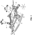
- FIG. 1 illustrates a vehicle impact absorbing structure 1.
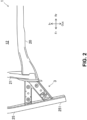
- FIG. 2 illustrates a left portion in a vehicle front portion.
- the impact absorbing structure 1 is applied to the vehicle front portion.
- the impact absorbing structure 1 absorbs an impact during a full-frontal collision, an offset collision, or a small overlap collision of the vehicle.
- the impact absorbing structure 1 includes two side frames 20.
- the side frames 20 are located below a front frame, which is not illustrated.
- the side frames 20 each extend in a vehicle front-rear direction from a dashboard for separating a cabin 11 and an engine compartment 12 toward the front of the vehicle.
- the engine compartment 12 houses an internal combustion engine and/or an electric motor.
- the side frames 20 are aligned with a space therebetween in a vehicle width direction.
- the vehicle width direction is a direction orthogonal to the vehicle front-rear direction.
- a first crossmember 21, a second crossmember 22, and a third crossmember 23 are located between the two side frames 20.
- the first crossmember 21 extends in the vehicle width direction to connect front ends of the side frames 20.
- Behind the first crossmember 21, the second crossmember 22 connects the side frames 20 in the vehicle width direction.
- the second crossmember 22 is a suspension crossmember that supports right and left suspensions 24.
- the third crossmember 23 extends in the vehicle width direction to connect rear ends of the side frames 20.
- the impact absorbing structure 1 includes a bumper beam 25.
- the bumper beam 25 In front of the side frames 20, the bumper beam 25 extends in the vehicle width direction.
- the bumper beam 25 supports a lower portion of a vehicle front bumper.
- the bumper beam 25 has a beam end portion 251 that is located on an outer side of the side frame 20 in the vehicle width direction.
- the beam end portion 251 is inclined rearward to the outer side in the vehicle width direction.
- the impact absorbing structure 1 includes impact absorbing members 3.
- the impact absorbing members 3 each couple the front end of the side frame 20 and the bumper beam 25 in the vehicle front-rear direction.
- the impact absorbing members 3 are compressively deformed by an impact load that is input to the bumper beam 25 from the front of the vehicle.
- the impact absorbing members 3 each have a function to absorb energy by compressive deformation and a function to transmit the impact load to the side frame 20.
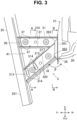
- FIG. 3 is a plan view in which the impact absorbing member 3 is enlarged.
- a top view of FIG. 4 is an end view that is taken along A-A in FIG. 3
- a bottom view of FIG. 4 is an end view that is taken along B-B in FIG. 3 .
- FIG. 5 includes exploded views of the impact absorbing member 3.
- the impact absorbing structure 1 includes a set plate 26.
- the set plate 26 is attached to the front end of the side frame 20.
- a rear end of the impact absorbing member 3 is joined to the set plate 26.
- the set plate 26 has a body section 261 and a convex section 262.
- the body section 261 is a flat plate that expands in up-down and right-left directions, and is fixed to the front end of the side frame 20.
- the convex section 262 is a portion that protrudes from the body section 261 toward the front of the vehicle.
- the convex section 262 has a rectangular shape in vehicle front view (also see FIG. 7 ).
- the convex section 262 has an inclined surface 263 at an outer position in the vehicle width direction. As will be described below, the inclined surface 263 is a joint surface to which a part of the rear end of the impact absorbing member 3 is joined. Further, the convex section 262 has a flat front surface surrounded by the inclined surface.
- the impact absorbing member 3 has a first portion 31 and a second portion 32. As illustrated in FIG. 4 , the first portion 31 and the second portion 32 are located at positions that are the same in the up-down direction and shifted from each other in the vehicle width direction.
- the first portion 31 extends toward the front of the vehicle in the vehicle front-rear direction from the front end of the side frame 20, more precisely, the set plate 26.
- An extending direction of the first portion 31 and an extending direction of the side frame 20 are the same or substantially the same.
- a front end of the first portion 31 is joined to a portion of the bumper beam 25 that is not the beam end portion 251.
- the second portion 32 extends from the front end of the side frame 20 toward the front of the vehicle while being inclined outward in the vehicle width direction.
- the second portion 32 is joined to the beam end portion 251 of the bumper beam 25.
- the first portion 31 has an upper plate section 33, a lower plate section 34, and an intermediate plate section 35.
- a top view 5A of FIG. 5 illustrates a state where the upper plate section 33, the lower plate section 34, and the intermediate plate section 35 are stacked in the up-down direction to form the first portion 31.
- a middle view 5B illustrates a state where only the upper plate section 33 is removed and the intermediate plate section 35 is exposed.
- a bottom view 5C illustrates a state where the upper plate section 33 and the intermediate plate section 35 are removed and the lower plate section 34 is visible from above.
- the upper plate section 33 has a transverse cross section in an inverted U-shape and is located on top of the intermediate plate section 35. Lower ends of the upper plate section 33 are joined to the intermediate plate section 35 by line welding.
- the lower plate section 34 has a transverse cross section in a U-shape and is located beneath the intermediate plate section 35. Upper ends of the lower plate section 34 are joined to the intermediate plate section 35 by line welding.
- a closed cross-sectional structure of the first portion 31 is formed by joining the upper plate section 33, the intermediate plate section 35, and the lower plate section 34 stacked in the up-down direction.
- the first portion 31 has two closed cross sections that are a first closed cross section 311 and a second closed cross section 312.
- the first closed cross section 311 and the second closed cross section 312 are stacked in the up-down direction.
- the first portion 31 has a bead 36 and notches 37. Both the bead 36 and the notches 37 promote compressive deformation of the first portion 31.
- the bead 36 is formed in each of the upper plate section 33 and the lower plate section 34.
- the bead 36 is located in a tip portion of the upper plate section 33.
- a bead of the lower plate section 34 is also located at the same position as the bead 36 of the upper plate section 33.
- the notches 37 are formed on the ridgelines 310 of each of the upper plate section 33 and the lower plate section 34. In the upper plate section 33 and the lower plate section 34, a plurality of the notches 37 are formed at spaced intervals in the vehicle front-rear direction.
- the second portion 32 has an upper plate section 38 and a lower plate section 39.
- the top view 5A of FIG. 5 illustrates a state where the upper plate section 38 and the lower plate section 39 are stacked in the up-down direction to form the second portion 32.
- the middle view 5B illustrates a state where the upper plate section 38 is removed and the lower plate section 39 is visible from above.
- the upper plate section 38 has a transverse cross section in the inverted U-shape.
- a lower end of the upper plate section 38 on the outer side in the vehicle width direction is folded horizontally to form a joint flange 381.
- the lower plate section 39 has a transverse cross section in the U-shape.
- An upper end of the lower plate section 39 on the outer side in the vehicle width direction is folded horizontally to form a joint flange 391.
- the joint flange 391 is also formed on an inner side of the lower plate section 34 in the vehicle width direction.
- a closed cross-sectional structure of the second portion 32 is formed by joining the joint flange 381 of the upper plate section 38 to the joint flange 391 of the lower plate section 39, which are stacked in the up-down direction, and joining the lower end of the upper plate section 38 on the inner side in the vehicle width direction to the joint flange 391 of the lower plate section 39 by welding.
- the second portion 32 has one closed cross section. As illustrated in FIG. 3 , ridgelines 320 of the second portion 32, which are defined by corners of the upper plate section 38 and corners of the lower plate section 39, extend in a direction that is inclined with respect to the vehicle front-rear direction.
- the second portion 32 also has second ridgelines 321, each of which is defined by a corner formed by the joint flange 381 and the joint flange 391, on the inside of the second portion 32 (see FIG. 4 ).
- the second ridgelines 321 also extend in the direction inclined with respect to the vehicle front-rear direction.
- the second portion 32 also has beads 313 and notches 314. Both the beads 313 and the notches 314 promote compressive deformation of the second portion 32.
- the beads 313 are formed in each of the upper plate section 38 and the lower plate section 39. The beads 313 are located at two spaced positions in a tip portion of the upper plate section 38.
- the beads 313 of the lower plate section 39 are also located at the same positions as the beads 313 of the upper plate section 38 (see FIG. 6 ).
- the notches 314 are formed on the ridgelines 320 of each of the upper plate section 38 and the lower plate section 39. In the upper plate section 38 and the lower plate section 39, a plurality of the notches 314 are formed at spaced intervals in the vehicle front-rear direction.
- FIG. 6 is a perspective view of the common member 4.
- the common member 4 as a whole has a substantially trapezoidal shape in plan view.
- An inner portion in the vehicle width direction of the common member 4 forms the intermediate plate section 35 of the first portion 31.
- This portion has a flat plate shape.
- An outer portion in the vehicle width direction of the common member 4 forms the lower plate section 39 of the second portion 32.
- This portion has a groove shape that is recessed downward.
- the common member 4 is provided across the first portion 31 and the second portion 32 and forms a part of each of the first portion 31 and the second portion 32.
- a plate thickness t1 of the common member 4 is greater than a plate thickness t2 of the upper plate section 33 and a plate thickness t3 of the lower plate section 34 of the first portion 31 and a plate thickness t4 of the upper plate section 38 of the second portion 32.
- the common member 4 has a removed section 41. As illustrated in the top view of FIG. 4 , the removed section 41 is located between the intermediate plate section 35 of the first portion 31 and the lower plate section 39 of the second portion 32. The removed section 41 has a substantially triangular shape in plan view. The removed section 41 reduces weight of the impact absorbing member 3 without compromising the function of the impact absorbing member 3.
- the width W1 in the vehicle width direction of the first portion 31 is compared to a width W2 in the vehicle width direction of the second portion 32
- the width W2 of the second portion 32 is greater.
- the second portion 32 has higher bending rigidity in the vehicle width direction.
- the cross-sectional area of the second portion 32 is larger.
- the second portion 32 having the larger cross-sectional area has the relatively high bending rigidity in the vehicle width direction.
- FIG. 7 illustrates a positional relationship among a rear end of the first portion 31, a rear end of the second portion 32, and the front end of the side frame 20 in vehicle front view.
- the first portion 31 and the second portion 32 are located at the same height positions in the up-down direction.
- the rear end of the second portion 32 is located on the outer side of the rear end of the first portion 31 in the vehicle width direction.
- the rear end of the first portion 31 and the rear end of the second portion 32 overlap the front end of the side frame 20 in vehicle front view.
- the overlap of the rear end of the first portion 31 means that an imaginary surface surrounded by an outer peripheral edge of the rear end of the hollow first portion 31 partially overlaps an imaginary surface surrounded by an outer peripheral edge of the front end of the side frame 20, which is also hollow, in the vehicle front-rear direction.
- the overlap of the rear end of the second portion 32 means that an imaginary surface surrounded by an outer peripheral edge of the rear end of the hollow second portion 32 partially overlaps the imaginary surface surrounded by the outer peripheral edge of the front end of the side frame 20 in the vehicle front-rear direction.
- an end surface center C1 of the rear end of the first portion 31 is located in an end surface of the front end of the side frame 20.
- an end surface center C2 of the rear end of the second portion 32 is located in the end surface of the front end of the side frame 20.
- an end surface center C3 of the front end of the side frame 20 is located in the end surface of the rear end of the second portion 32.
- Both an upper end of the first portion 31 and an upper end of the second portion 32 are located slightly above an upper end of the side frame 20.
- the first portion 31, the second portion 32, and the side frame 20 each have the closed cross-sectional structure including vertical walls and horizontal walls.
- the vertical wall of the first portion 31 and the vertical wall of the second portion 32 overlap the horizontal wall of the side frame 20 in the vehicle front view.
- the upper end of the first portion 31 or the upper end of the second portion 32 may each be located at the same position as the upper end of the side frame 20.
- the upper end of the first portion 31 or the upper end of the second portion 32 may be located slightly below the upper end of the side frame 20.
- a lower end of the first portion 31 or a lower end of the second portion 32 may be located slightly above a lower end of the side frame 20, at the same position as the lower end of the side frame 20, or slightly below the lower end of the side frame 20.
- both of the two ridgelines 320 of the second portion 32 continue from the bumper beam 25 to the set plate 26. While an inner portion in the vehicle width direction of the rear end of the first portion 31 is joined to the set plate 26, an outer portion in the vehicle width direction of the rear end of the first portion 31 does not reach the set plate 26. The outer portion in the vehicle width direction of the rear end of the first portion 31 abuts a side surface of the second portion 32.
- the inner ridgeline 310 in the vehicle width direction continues from the bumper beam 25 to the set plate 26.
- the outer ridgeline 310 in the vehicle width direction of the first portion 31 abuts a side portion of the second portion 32.
- the vehicle impact absorbing structure 1 includes the impact absorbing members 3.
- the impact absorbing members 3 are each located between the side frame 20 and the bumper beam 25 and compressively deformed by the impact load that is input to the bumper beam 25 from the front of the vehicle.
- the impact absorbing members 3 each exert an energy absorption function through compressive deformation and transmit the impact load to the side frame 20.
- the impact absorbing members 3 each have the first portion 31 and the second portion 32.
- the second portion 32 is a portion that primarily functions during the small overlap collision.
- FIG. 8 is a view exemplifying behavior of the impact absorbing member 3 during the small overlap collision.
- a colliding object 51 collides with the beam end portion 251.
- the second portion 32 extends from the front end of the side frame 20 toward the front of the vehicle while being inclined outward in the vehicle width direction, and is joined to the beam end portion 251 of the bumper beam 25.
- the second portion 32 transmits the impact load to the side frame 20 while being compressively deformed by the impact load input to the beam end portion 251.
- the second portion 32 has the energy absorption function. Since the first portion 31 does not come into contact with the colliding object 51 during the small overlap collision, the first portion 31 hardly contributes to energy absorption.
- an impact load F that is input to the front end of the side frame 20 through the second portion 32 is broken down into a load F1 in the vehicle front-rear direction and a load F2 that is directed inward in the vehicle width direction.
- the load F2 that is directed inward in the vehicle width direction is a reaction force that is directed inward in the vehicle width direction, and causes the vehicle to move inward in the vehicle width direction. Since the vehicle moves in a direction away from the colliding object 51, the colliding object 51 is suppressed from coming into contact with the cabin 11 behind the side frame 20.
- the impact absorbing member 3 exerts the following functions by the second portion 32; (1) the energy absorption function, (2) the function to transmit the impact load to the side frame 20, and (3) a function to generate the reaction force directed inward in the vehicle width direction.
- the vehicle impact absorbing structure 1 enhances collision performance during the small overlap collision.
- the second portion 32 itself has the energy absorption function. Since the second portion 32 is not a portion that merely contacts the first portion 31 as in the related art, a reinforcement structure that assumes the contact with the second portion 32 can be omitted in the impact absorbing member 3. Therefore, the vehicle weight is reduced.
- the first portion 31 comes into contact with the colliding object during the full-frontal collision or the offset collision.
- the first portion 31 is a portion that functions during the full-frontal collision or the offset collision.
- FIG. 9 is a view exemplifying the behavior of the impact absorbing member 3 during the full-frontal collision.
- the first portion 31 extends from the front end of the side frame 20 toward the front of the vehicle in the vehicle front-rear direction.
- the first portion 31 is compressively deformed by an impact load in the vehicle front-rear direction, which is input by a colliding object 52.
- the rear end of the first portion 31 overlaps the front end of the side frame 20.
- the impact load is efficiently input to the side frame 20 via the first portion 31.
- the first portion 31 absorbs the energy and transmits the impact load to the side frame 20.
- the second portion 32 is also compressively deformed by the impact load in the vehicle front-rear direction, which is input by the colliding object 52.
- the second portion 32 together with the first portion 31, absorbs the energy and assists in transmitting the impact load to the side frame 20.
- the rear end of the second portion 32 is located on the outer side of the rear end of the first portion 31 in the vehicle width direction, and the rear end of the second portion 32 overlaps the front end of the side frame 20 in the vehicle front view.
- the second portion 32 can efficiently transmit the impact load, which is input to the beam end portion 251, to the front end of the side frame 20.
- the second portion 32 can stably exert the three functions (1), (2), and (3).
- the rear end of the impact absorbing member 3 is joined to the set plate 26.
- at least part of the rear end of the impact absorbing member 3 is joined to the convex section 262 of the set plate 26.
- the set plate 26 having the convex section 262 has high rigidity.
- the impact absorbing member 3 can efficiently transmit the impact load to the side frame 20 via the set plate 26.
- the second portion 32 is inclined with respect to the vehicle front-rear direction.
- a portion, to which the rear end of the second portion 32 is joined, on the outer side in the vehicle width direction would be the body section 261 of the set plate 26, as illustrated in FIG. 3
- an angle defined by the rear end of the second portion 32 and the body section 261 as the joint portion would be an acute angle in plan view.
- the rear end of the second portion 32 is joined to the inclined surface 263 of the convex section 262.
- the inclined surface 263 makes a joint angle ⁇ between the rear end of an outer vertical wall of the second portion 32 and the joint portion a right angle or substantially a right angle. With a large joint angle ⁇ , a space is secured for welding work during assembly of the vehicle impact absorbing structure 1.
- the inclined surface 263 allows the rear end of the outer vertical wall of the second portion 32 to be joined to the set plate 26 by line welding. Further, rear ends of an upper and a lower horizontal wall of the second portion 32 are joined to the flat front surface of the convex section 262.
- the end surface center C1 of the rear end of the first portion 31 and the end surface center C2 of the rear end of the second portion 32 are located in the end surface of the front end of the side frame 20.
- An area where a rear end surface of the first portion 31 and a rear end surface of the second portion 32 overlap a front end surface of the side frame 20 is relatively large.
- Each of the first portion 31 and the second portion 32 can efficiently transmit the impact load to the front end of the side frame 20.
- the end surface center C3 of the front end of the side frame 20 is located in the end surface of the rear end of the second portion 32.
- An area where the rear end surface of the second portion 32 overlaps the front end surface of the side frame 20 is relatively large. The second portion 32 can efficiently transmit the impact load during the small overlap collision to the front end of the side frame 20.
- the vertical wall of the first portion 31 and the vertical wall of the second portion 32 overlap the horizontal wall of the side frame 20 in the vehicle front view.
- Each of the first portion 31 and the second portion 32 can directly transmit the impact load to the side frame 20.
- the stable transmission of the impact load improves the collision performance of the vehicle impact absorbing structure 1.
- the ridgelines 320 of the second portion 32 continue from the bumper beam 25 to the front end of the side frame 20. During the small overlap collision, the second portion 32 can further efficiently transmit the impact load, which is input to the beam end portion 251, to the front end of the side frame 20.
- the second portion 32 is prioritized, and the ridgelines 320 are made to continue to the set plate 26.
- the rear end of the first portion 31 and the rear end of the second portion 32 are joined to the set plate 26.
- Each of the first portion 31 and the second portion 32 can efficiently transmit the impact load to the front end of the side frame 20.
- the width W1 in the vehicle width direction of the first portion 31 is compared to the width W2 in the vehicle width direction of the second portion 32, the width W2 of the second portion 32 is greater.
- the second portion 32 has the higher bending rigidity in the vehicle width direction than the first portion 31.
- the second portion 32 is inclined with respect to the vehicle front-rear direction.
- the impact absorbing member 3 is a member in which the bending rigidity of the second portion 32, which is the bending rigidity against the load in the vehicle width direction, is higher than the bending rigidity of the first portion 31, which is the bending rigidity against the load in the vehicle width direction.
- the high bending rigidity prevents the second portion 32 from being bent outward in the vehicle width direction.
- the second portion 32 is not bent but compressively deformed.
- the second portion 32 can efficiently transmit the impact load to the side frame 20 while absorbing the energy through compressive deformation.
- the impact absorbing member 3 can stably exert the three functions described above.
- the cross-sectional area of the second portion 32 is larger than the cross-sectional area of the first portion 31.
- the large cross-sectional area is advantageous in improving the bending rigidity of the second portion 32.
- the first portion 31 has the closed cross-sectional structure that has the first closed cross section 311 and the second closed cross section 312 aligned in the up-down direction.
- the first portion 31 having the closed cross-sectional structure efficiently transmits the impact load to the side frame 20 while being compressively deformed by the impact load.
- the first portion 31 since the first portion 31 has the first closed cross section 311 and the second closed cross section 312, energy absorption capacity thereof during the compressive deformation is high.
- the first portion 31 can have the required bending rigidity even with the small cross-sectional area.
- the second portion 32 has the closed cross-sectional structure in which the upper plate section 38 and the lower plate section 39 are stacked and joined to each other in the up-down direction, and the upper plate section 38 and the lower plate section 39 have the joint flanges 381, 391, respectively.
- the second portion 32 having the closed cross-sectional structure is advantageous in improving the bending rigidity.
- the second portion 32 having the joint flanges 381, 391 has the second ridgelines 321, each of which is the corner formed by bending and extends from one end to the other end of the second portion 32.
- the bending rigidity of the second portion 32 is further increased, and during the input of the impact load, the second portion 32 stably realize both the absorption of the energy through the compressive deformation and the transmission of the impact load to the side frame 20.
- the second portion 32 is inclined with respect to the vehicle front-rear direction.
- the inclined second portion 32 possibly collapses outward in the vehicle width direction.
- the impact absorbing member 3 has the common member 4.
- the common member 4 is provided across the first portion 31 and the second portion 32 and forms a part of each of the first portion 31 and the second portion 32.
- the common member 4 suppresses the second portion 32 from collapsing outward in the vehicle width direction by the rigidity of the common member 4.
- the second portion 32 does not collapse.
- the second portion 32 the collapse of which is suppressed, can efficiently transmit the impact load to the side frame 20 while absorbing the energy through the compressive deformation.
- the impact absorbing member 3 can stably exert the three functions described above.
- the common member 4 is the intermediate plate section 35, which is located between the first closed cross section 311 and the second closed cross section 312 in the first portion 31, and the lower plate section 39, which is located at the bottom of the closed cross section in the second portion 32.
- the first portion 31 and the second portion 32 that are formed by including the common member 4 efficiently transmit the impact load to the side frame 20 while being compressively deformed by the impact load.
- the impact absorbing member 3 exerts the improved collision performance while being lightweight.
- the first portion 31 has the two closed cross sections that are the first closed cross section 311 and the second closed cross section 312.
- the first portion 31 can ensure the high energy absorption function despite being lightweight.
- the plate thickness t1 of the intermediate plate section 35 is greater than the plate thickness t2 of the upper plate section 33 and the plate thickness t3 of the lower plate section 34. Since the plate thickness t1 of the intermediate plate section 35 is relatively great, the first portion 31 can ensure the high energy absorption function associated with the compressive deformation.
- the common member 4 having the great plate thickness t1 is highly rigid, the common member 4 can effectively suppress the second portion 32 from collapsing outward in the vehicle width direction during the small overlap collision.
- the common member 4 has the removed section 41 between the first portion 31 and the second portion 32.
- the removed section 41 reduces the weight of the impact absorbing member 3 without compromising the function of the common member 4.
- the vehicle impact absorbing structure 1 can improve the collision performance during the small overlap collision without increasing the vehicle weight.
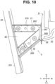
- FIG. 10 illustrates a modified embodiment of the vehicle impact absorbing structure 1.
- FIG. 10 illustrates a modified embodiment of the common member.
- FIG. 11 illustrates a common member 42 according to the modified embodiment.
- the common member 42 does not have a removed section. Rigidity of the common member 42, which does not have the removed section, is even higher.
- the common member 42 can further suppress the second portion 32 from collapsing outward in the vehicle width direction.
- the common member 42 which does not have the removed section, has the high energy absorption capacity.
- the impact absorbing member 3 can sufficiently absorb the impact load during various collisions.
- FIG. 12 illustrates further another modified embodiment of the common member.
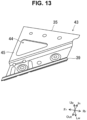
- FIG. 13 illustrates a common member 43 according to the modified embodiment.
- the common member 43 has a removed section 44 in a different shape from that in FIG. 6 .
- the common member 43 has a coupling section 45 in a front end portion.
- the coupling section 45 couples the intermediate plate section 35 of the first portion 31 and the lower plate section 39 of the second portion 32 in the vehicle width direction. Since the coupling section 45 supports the front end portion of the second portion 32, the common member 43 is highly effective in suppressing the second portion 32 from collapsing outward in the vehicle width direction despite being lightweight.
- the vehicle impact absorbing structure disclosed herein is not limited to application to the side frame but can also be applied to the front frame.
- the impact absorbing member 3 may be attached to a tip of the front frame.
Landscapes
- Engineering & Computer Science (AREA)
- Mechanical Engineering (AREA)
- Chemical & Material Sciences (AREA)
- Combustion & Propulsion (AREA)
- Transportation (AREA)
- Body Structure For Vehicles (AREA)
Abstract
[Problem] To improve collision performance during a small overlap collision without increasing vehicle weight.
[Solution] A vehicle impact absorbing structure 1 includes a side frame 20, a bumper beam 25, and an impact absorbing member 3 compressively deformed by an impact load input to the bumper beam from the front of a vehicle. The impact absorbing member has a first portion 31 and a second portion 32 that extends from a front end of the side frame toward the front of the vehicle while being inclined outward in a vehicle width direction and is joined to a beam end portion 251 of the bumper beam. At least a part of a rear end of the second portion is located on an outer side of a rear end of the first portion in the vehicle width direction, and the rear end of the first portion and the rear end of the second portion overlap a front end of the side frame in vehicle front view.
Description
- A technique disclosed herein relates to a vehicle impact absorbing structure.
- A conventional vehicle body front structure is described in Patent Literature 1 (
JP2018-118565A - More specifically, the conventional vehicle body front structure includes an extension side member 14 and an extension crossmember 16. The extension side member 14 is located between a front end surface of a
side member 12 and a crossmember 15, and is buckled and deformed during a collision to absorb the impact load. At a position on a rear surface of the crossmember 15 and on an outer side of the extension side member 14 in the vehicle width direction, the extension crossmember 16 protrudes from a rear surface of the crossmember 15 toward a vehicle body rear side. - During the small overlap collision, a side end portion in the vehicle width direction of the crossmember 15 is deformed inward in the vehicle width direction with an intersection point 15b between the crossmember 15 and the extension side member 14 being a rotation center. Along with deformation of the crossmember 15, the extension crossmember 16 rotates inward in the vehicle width direction with the intersection point 15b being the rotation center. The extension crossmember 16 then comes into contact with a side surface of the extension side member 14.
- The extension crossmember 16 in the conventional vehicle body front structure only has a function to transmit the impact load to the
side member 12 during the small overlap collision. The extension crossmember 16 itself has high rigidity that prevents deformation during the collision, and weight thereof is relatively heavy. - The extension crossmember 16 is arranged not to contact the
side member 12 during the offset collision, which is not the small overlap collision. This is because the contact of the extension crossmember 16 having the high rigidity with theside member 12 may interfere with buckling deformation of the extension side member 14. The extension crossmember 16 does not exert any function during the offset collision and a full-frontal collision. - A disadvantage of the extension crossmember 16 is that, despite its poor functionality, the extension crossmember 16 significantly increases vehicle weight.
- The extension side member 14 has a reinforcement plate 17. This is because the extension crossmember 16 hits the side surface of the extension side member 14 during the small overlap collision. The reinforcement plate 17 suppresses crushing deformation of the extension side member 14 in the vehicle width direction. The extension crossmember 16 causes a weight increase of the extension side member 14.
- An object of the present invention is to improves collision performance during a small overlap collision without increasing vehicle weight.
- This object is solved by a vehicle impact absorbing structure according to
claim 1. Preferred embodiments are the subject matter of the dependent claims. - The present invention provides a vehicle impact absorbing structure. The vehicle impact absorbing structure includes:
- a side frame that extends in a vehicle front-rear direction in a vehicle front portion;
- a bumper beam that extends in a vehicle width direction in front of the side frame, the bumper beam having a beam end portion located on an outer side of the side frame in the vehicle width direction; and
- an impact absorbing member that couples a front end of the side frame and the bumper beam in the vehicle front-rear direction, the impact absorbing member being compressively deformed by an impact load that is input to the bumper beam from the front of the vehicle, in which
- the impact absorbing member has:
- a first portion that extends from the front end of the side frame toward the front of the vehicle in the vehicle front-rear direction and is joined to the bumper beam; and
- a second portion that extends from the front end of the side frame toward the front of the vehicle while being inclined outward in the vehicle width direction, and is joined to the beam end portion of the bumper beam, and
- at least a part of a rear end of the second portion is located on the outer side of a rear end of the first portion in the vehicle width direction, and the rear end of the first portion and the rear end of the second portion overlap the front end of the side frame in vehicle front view.
- The vehicle impact absorbing structure includes the impact absorbing member. The impact absorbing member is located between the side frame and the bumper beam. The impact absorbing member is compressively deformed by the impact load that is input to the bumper beam from the front of the vehicle. The impact absorbing member exerts an energy absorption function through compressive deformation and transmits the impact load to the side frame.
- The impact absorbing member has the first portion and the second portion. The first portion extends from the front end of the side frame toward the front of the vehicle in the vehicle front-rear direction. The first portion is compressively deformed by a colliding object during a full-frontal collision or an offset collision. Here, the full-frontal collision is a collision in which an entire front surface of the vehicle comes into contact with the colliding object. In addition, the offset collision described herein is an offset collision that is not a small overlap collision described below. The first portion absorbs energy and transmits the impact load to the side frame when being compressively deformed by the impact load in the vehicle front-rear direction.
- In the vehicle front view, the rear end of the first portion overlaps the front end of the side frame. During the full-frontal collision or the offset collision, the impact load is efficiently input to the side frame via the first portion.
- The second portion extends from the front end of the side frame toward the front of the vehicle while being inclined outward in the vehicle width direction, and is joined to the beam end portion of the bumper beam. During the small overlap collision, the colliding object collides with the beam end portion. The second portion, which connects the beam end portion and the front end of the side frame, transmits the impact load to the side frame while being compressively deformed by the impact load input to the beam end portion. The second portion has an energy absorption function.
- Since the second portion is inclined with respect to the vehicle front-rear direction, the impact load that is input to the front end of the side frame through the second portion is broken down into a load in the vehicle front-rear direction and a load that is directed inward in the vehicle width direction. The load that is directed inward in the vehicle width direction is a reaction force that is directed inward in the vehicle width direction, and causes the vehicle to move inward in the vehicle width direction. Since the vehicle moves in a direction away from the colliding object, the colliding object is suppressed from coming into contact with a cabin behind the side frame.
- During the small overlap collision, the impact absorbing member exerts the following functions by the second portion; (1) the energy absorption function, (2) the function to transmit the impact load to the side frame, and (3) the function to generate the reaction force directed inward in the vehicle width direction. The vehicle impact absorbing structure enhances collision performance during the small overlap collision. In addition, since the second portion itself has the energy absorption function, the energy absorption function of another component can be simplified for the energy absorption function of the second portion. The second portion having the energy absorption function is advantageous in reducing weight of the vehicle.
- In addition, since the second portion is not a portion that comes into contact with another component such as the first portion, a reinforcement structure that assumes the contact with the second portion can be omitted. Therefore, the weight of the vehicle is reduced.
- At least a part of the rear end of the second portion is located on the outer side of the rear end of the first portion in the vehicle width direction, and the rear end of the second portion overlaps the front end of the side frame in vehicle front view. The second portion can efficiently transmit the impact load, which is input to the beam end portion, to the front end of the side frame. The second portion can stably exert the three functions described above.
- In an embodiment, the vehicle impact absorbing structure further includes a set plate that is interposed between the impact absorbing member and the front end of the side frame, in which
- the set plate may have a convex section that protrudes from the front end of the side frame toward the front of the vehicle, and
- at least a part of a rear end of the impact absorbing member may be joined to the convex section.
- The set plate having the convex section has high rigidity. Since the rear end of the impact absorbing member is joined to the convex section, the impact absorbing member can efficiently transmit the impact load to the side frame via the set plate.
- The set plate may comprise a body section, which is a flat plate that expands in up-down and right-left directions, and is fixed to the front end of the side frame, wherein the convex section may be a portion that protrudes from the body section toward the front of the vehicle.
- In the vehicle impact absorbing structure according to the above described aspect, a part of the rear end of the first portion may be joined to the body section of the set plate.
- In the vehicle impact absorbing structure according to the present invention, at least a part of the rear end of the first portion and an entirety of the rear end of the second portion my be joined to the convex section of the set plate.
- In the vehicle impact absorbing structure according to the present invention, the convex section might have an inclined surface at an outer position in the vehicle width direction.
- In an embodiment of the present invention, the convex section has an inclined surface at an outer position in the vehicle width direction.
- In an embodiment of the present invention, a rear end of an outer vertical wall of the second portion is joined to the inclined surface of the convex section. In the vehicle impact absorbing structure according to the above described aspect, the rear end of the second portion might be joined to the inclined surface of the convex section at a right angle or almost right angle.
- In an embodiment of the present invention, the convex section has a flat front surface surrounded by the inclined surface, wherein rear ends of an upper and a lower horizontal wall of the second portion are joined to the flat front surface of the convex section.
- The first portion and the second portion may each have a closed cross-sectional structure including a corner,
- a ridgeline of the corner of the second portion may continue from the bumper beam to the front end of the side frame, and
- a part of the rear end of the first portion may abut a side portion of the second portion.
- Both the first portion and the second portion having the closed cross-sectional structures can stably exert the energy absorption function through the compressive deformation in response to the impact load and a function to transmit the impact load to the side frame.
- The ridgeline of the corner of the second portion continues from the bumper beam to the front end of the side frame. During the small overlap collision, the second portion can further efficiently transmit the impact load, which is input to the beam end portion, to the front end of the side frame.
- A part of the rear end of the first portion abuts the side portion of the second portion, and a remaining part of the rear end of the first portion is joined to the front end of the side frame. In other words, in a state of being in close proximity to each other in the vehicle width direction, the rear end of the first portion and the rear end of the second portion are joined to the front end of the side frame. Each of the first portion and the second portion can efficiently transmit the impact load to the front end of the side frame.
- In the vehicle front view, an end surface center of the rear end of the first portion and an end surface center of the rear end of the second portion are located in an end surface of the front end of the side frame.
- In the vehicle front view, an area where a rear end surface of the first portion and a rear end surface of the second portion overlap a front end surface of the side frame is relatively large. Each of the first portion and the second portion can efficiently transmit the impact load to the front end of the side frame.
- In the vehicle front view, the end surface center of the front end of the side frame may be located in the end surface of the rear end of the second portion.
- In the vehicle front view, an area where the rear end surface of the second portion overlaps the front end surface of the side frame is relatively large. The second portion can efficiently transmit the impact load to the front end of the side frame.
- The side frame may have a closed cross-sectional structure including vertical walls and horizontal walls,
- the first portion and the second portion may each have a closed cross-sectional structure including vertical walls and horizontal walls, and
- the vertical walls of the first portion and the second portion may overlap one of the horizontal walls of the side frame in the vehicle front view.
- Each of the first portion and the second portion can directly transmit the impact load to the side frame. The stable transmission of the impact load improves the collision performance of the vehicle impact absorbing structure.
- In an embodiment, the vertical walls of the first portion and the second portion overlap an upper horizontal wall of the side frame in the vehicle front view, wherein preferably, upper horizontal walls of the first portion and the second portion extend above an upper horizontal wall of the side frame.
- In an embodiment of the present invention, the impact absorbing member has a common member that is provided across the first portion and the second portion and forms a part of each of the first portion and the second portion.
- In an embodiment of the present invention, the common member is a bent metal plate.
- The present invention further comprises a vehicle comprising a vehicle impact absorbing structure as described above.
- The vehicle impact absorbing structure can improve the collision performance during the small overlap collision without increasing the vehicle weight.[Brief Description of Drawings]
- [
FIG. 1] FIG. 1 illustrates a vehicle impact absorbing structure. - [
FIG. 2] FIG. 2 illustrates a left portion in a vehicle front portion. - [
FIG. 3] FIG. 3 is a plan view of an impact absorbing member. - [
FIG. 4] FIG. 4 includes a top view that is an end view taken along A-A inFIG. 3 and a bottom view that is an end view taken along B-B inFIG. 3 . - [
FIG. 5] FIG. 5 includes perspective views of the impact absorbing member from which some members are sequentially removed. - [
FIG. 6] FIG. 6 is a perspective view of a common member in the impact absorbing member. - [
FIG. 7] FIG. 7 is a cross-sectional explanatory view illustrating a positional relationship among a rear end of a first portion, a rear end of a second portion, and a front end of a side frame. - [
FIG. 8] FIG. 8 is a view exemplifying behavior of the impact absorbing member during a small overlap collision. - [
FIG. 9] FIG. 9 is a view exemplifying the behavior of the impact absorbing member during a full-frontal collision. - [
FIG. 10] FIG. 10 is a plan view of an impact absorbing member according to a modified embodiment. - [
FIG. 11] FIG. 11 is a perspective view of a common member in the impact absorbing member according to the modified embodiment. - [
FIG. 12] FIG. 12 is a plan view of an impact absorbing member according to further another modified embodiment. - [
FIG. 13] FIG. 13 is a perspective view of a common member in the impact absorbing member according to the further other modified embodiment. - Embodiments of a vehicle impact absorbing structure are described below with reference to the drawings. The vehicle impact absorbing structure described herein is merely an example.
-
FIG. 1 illustrates a vehicleimpact absorbing structure 1.FIG. 2 illustrates a left portion in a vehicle front portion. - The
impact absorbing structure 1 is applied to the vehicle front portion. Theimpact absorbing structure 1 absorbs an impact during a full-frontal collision, an offset collision, or a small overlap collision of the vehicle. - The
impact absorbing structure 1 includes two side frames 20. The side frames 20 are located below a front frame, which is not illustrated. The side frames 20 each extend in a vehicle front-rear direction from a dashboard for separating acabin 11 and anengine compartment 12 toward the front of the vehicle. Theengine compartment 12 houses an internal combustion engine and/or an electric motor. - The side frames 20 are aligned with a space therebetween in a vehicle width direction. The vehicle width direction is a direction orthogonal to the vehicle front-rear direction. A
first crossmember 21, asecond crossmember 22, and athird crossmember 23 are located between the two side frames 20. Thefirst crossmember 21 extends in the vehicle width direction to connect front ends of the side frames 20. Behind thefirst crossmember 21, thesecond crossmember 22 connects the side frames 20 in the vehicle width direction. Thesecond crossmember 22 is a suspension crossmember that supports right and leftsuspensions 24. Thethird crossmember 23 extends in the vehicle width direction to connect rear ends of the side frames 20. - The
impact absorbing structure 1 includes abumper beam 25. In front of the side frames 20, thebumper beam 25 extends in the vehicle width direction. Thebumper beam 25 supports a lower portion of a vehicle front bumper. As illustrated inFIG. 2 , thebumper beam 25 has abeam end portion 251 that is located on an outer side of theside frame 20 in the vehicle width direction. Thebeam end portion 251 is inclined rearward to the outer side in the vehicle width direction. - The
impact absorbing structure 1 includesimpact absorbing members 3. Theimpact absorbing members 3 each couple the front end of theside frame 20 and thebumper beam 25 in the vehicle front-rear direction. Theimpact absorbing members 3 are compressively deformed by an impact load that is input to thebumper beam 25 from the front of the vehicle. Theimpact absorbing members 3 each have a function to absorb energy by compressive deformation and a function to transmit the impact load to theside frame 20. -
FIG. 3 is a plan view in which theimpact absorbing member 3 is enlarged. A top view ofFIG. 4 is an end view that is taken along A-A inFIG. 3 , and a bottom view ofFIG. 4 is an end view that is taken along B-B inFIG. 3 .FIG. 5 includes exploded views of theimpact absorbing member 3. - The
impact absorbing structure 1 includes aset plate 26. Theset plate 26 is attached to the front end of theside frame 20. A rear end of theimpact absorbing member 3 is joined to theset plate 26. - As illustrated in
FIG. 3 orFIG. 5 , theset plate 26 has abody section 261 and aconvex section 262. Thebody section 261 is a flat plate that expands in up-down and right-left directions, and is fixed to the front end of theside frame 20. Theconvex section 262 is a portion that protrudes from thebody section 261 toward the front of the vehicle. Theconvex section 262 has a rectangular shape in vehicle front view (also seeFIG. 7 ). As illustrated inFIG. 3 , theconvex section 262 has aninclined surface 263 at an outer position in the vehicle width direction. As will be described below, theinclined surface 263 is a joint surface to which a part of the rear end of theimpact absorbing member 3 is joined. Further, theconvex section 262 has a flat front surface surrounded by the inclined surface. - The
impact absorbing member 3 has afirst portion 31 and asecond portion 32. As illustrated inFIG. 4 , thefirst portion 31 and thesecond portion 32 are located at positions that are the same in the up-down direction and shifted from each other in the vehicle width direction. - The
first portion 31 extends toward the front of the vehicle in the vehicle front-rear direction from the front end of theside frame 20, more precisely, theset plate 26. An extending direction of thefirst portion 31 and an extending direction of theside frame 20 are the same or substantially the same. A front end of thefirst portion 31 is joined to a portion of thebumper beam 25 that is not thebeam end portion 251. - The
second portion 32 extends from the front end of theside frame 20 toward the front of the vehicle while being inclined outward in the vehicle width direction. Thesecond portion 32 is joined to thebeam end portion 251 of thebumper beam 25. - As illustrated in
FIG. 4 orFIG. 5 , thefirst portion 31 has anupper plate section 33, alower plate section 34, and anintermediate plate section 35. Atop view 5A ofFIG. 5 illustrates a state where theupper plate section 33, thelower plate section 34, and theintermediate plate section 35 are stacked in the up-down direction to form thefirst portion 31. Amiddle view 5B illustrates a state where only theupper plate section 33 is removed and theintermediate plate section 35 is exposed. Abottom view 5C illustrates a state where theupper plate section 33 and theintermediate plate section 35 are removed and thelower plate section 34 is visible from above. - The
upper plate section 33 has a transverse cross section in an inverted U-shape and is located on top of theintermediate plate section 35. Lower ends of theupper plate section 33 are joined to theintermediate plate section 35 by line welding. Thelower plate section 34 has a transverse cross section in a U-shape and is located beneath theintermediate plate section 35. Upper ends of thelower plate section 34 are joined to theintermediate plate section 35 by line welding. A closed cross-sectional structure of thefirst portion 31 is formed by joining theupper plate section 33, theintermediate plate section 35, and thelower plate section 34 stacked in the up-down direction. - The
first portion 31 has two closed cross sections that are a firstclosed cross section 311 and a secondclosed cross section 312. The firstclosed cross section 311 and the secondclosed cross section 312 are stacked in the up-down direction. As illustrated inFIG. 3 ,ridgelines 310 of thefirst portion 31, which are defined by corners of theupper plate section 33 and corners of thelower plate section 34, extend in the vehicle front-rear direction. - The
first portion 31 has abead 36 andnotches 37. Both thebead 36 and thenotches 37 promote compressive deformation of thefirst portion 31. Thebead 36 is formed in each of theupper plate section 33 and thelower plate section 34. Thebead 36 is located in a tip portion of theupper plate section 33. A bead of thelower plate section 34 is also located at the same position as thebead 36 of theupper plate section 33. Thenotches 37 are formed on theridgelines 310 of each of theupper plate section 33 and thelower plate section 34. In theupper plate section 33 and thelower plate section 34, a plurality of thenotches 37 are formed at spaced intervals in the vehicle front-rear direction. - As illustrated in
FIG. 4 orFIG. 5 , thesecond portion 32 has anupper plate section 38 and alower plate section 39. Thetop view 5A ofFIG. 5 illustrates a state where theupper plate section 38 and thelower plate section 39 are stacked in the up-down direction to form thesecond portion 32. Themiddle view 5B illustrates a state where theupper plate section 38 is removed and thelower plate section 39 is visible from above. - The
upper plate section 38 has a transverse cross section in the inverted U-shape. A lower end of theupper plate section 38 on the outer side in the vehicle width direction is folded horizontally to form ajoint flange 381. Thelower plate section 39 has a transverse cross section in the U-shape. An upper end of thelower plate section 39 on the outer side in the vehicle width direction is folded horizontally to form ajoint flange 391. Thejoint flange 391 is also formed on an inner side of thelower plate section 34 in the vehicle width direction. A closed cross-sectional structure of thesecond portion 32 is formed by joining thejoint flange 381 of theupper plate section 38 to thejoint flange 391 of thelower plate section 39, which are stacked in the up-down direction, and joining the lower end of theupper plate section 38 on the inner side in the vehicle width direction to thejoint flange 391 of thelower plate section 39 by welding. - The
second portion 32 has one closed cross section. As illustrated inFIG. 3 ,ridgelines 320 of thesecond portion 32, which are defined by corners of theupper plate section 38 and corners of thelower plate section 39, extend in a direction that is inclined with respect to the vehicle front-rear direction. Thesecond portion 32 also hassecond ridgelines 321, each of which is defined by a corner formed by thejoint flange 381 and thejoint flange 391, on the inside of the second portion 32 (seeFIG. 4 ). Thesecond ridgelines 321 also extend in the direction inclined with respect to the vehicle front-rear direction. - The
second portion 32 also hasbeads 313 andnotches 314. Both thebeads 313 and thenotches 314 promote compressive deformation of thesecond portion 32. Thebeads 313 are formed in each of theupper plate section 38 and thelower plate section 39. Thebeads 313 are located at two spaced positions in a tip portion of theupper plate section 38. Thebeads 313 of thelower plate section 39 are also located at the same positions as thebeads 313 of the upper plate section 38 (seeFIG. 6 ). Thenotches 314 are formed on theridgelines 320 of each of theupper plate section 38 and thelower plate section 39. In theupper plate section 38 and thelower plate section 39, a plurality of thenotches 314 are formed at spaced intervals in the vehicle front-rear direction. - The
impact absorbing members 3 each have acommon member 4.FIG. 6 is a perspective view of thecommon member 4. Thecommon member 4 as a whole has a substantially trapezoidal shape in plan view. An inner portion in the vehicle width direction of thecommon member 4 forms theintermediate plate section 35 of thefirst portion 31. This portion has a flat plate shape. An outer portion in the vehicle width direction of thecommon member 4 forms thelower plate section 39 of thesecond portion 32. This portion has a groove shape that is recessed downward. Thecommon member 4 is provided across thefirst portion 31 and thesecond portion 32 and forms a part of each of thefirst portion 31 and thesecond portion 32. - As illustrated in the bottom view of
FIG. 4 , a plate thickness t1 of thecommon member 4 is greater than a plate thickness t2 of theupper plate section 33 and a plate thickness t3 of thelower plate section 34 of thefirst portion 31 and a plate thickness t4 of theupper plate section 38 of thesecond portion 32. - The
common member 4 has a removedsection 41. As illustrated in the top view ofFIG. 4 , the removedsection 41 is located between theintermediate plate section 35 of thefirst portion 31 and thelower plate section 39 of thesecond portion 32. The removedsection 41 has a substantially triangular shape in plan view. The removedsection 41 reduces weight of theimpact absorbing member 3 without compromising the function of theimpact absorbing member 3. - As illustrated in
FIG. 4 , when a width W1 in the vehicle width direction of thefirst portion 31 is compared to a width W2 in the vehicle width direction of thesecond portion 32, the width W2 of thesecond portion 32 is greater. Thesecond portion 32 has higher bending rigidity in the vehicle width direction. In addition, when a cross-sectional area of thefirst portion 31 is compared to a cross-sectional area of thesecond portion 32, the cross-sectional area of thesecond portion 32 is larger. Thesecond portion 32 having the larger cross-sectional area has the relatively high bending rigidity in the vehicle width direction. -
FIG. 7 illustrates a positional relationship among a rear end of thefirst portion 31, a rear end of thesecond portion 32, and the front end of theside frame 20 in vehicle front view. As described above, thefirst portion 31 and thesecond portion 32 are located at the same height positions in the up-down direction. The rear end of thesecond portion 32 is located on the outer side of the rear end of thefirst portion 31 in the vehicle width direction. - In addition, the rear end of the
first portion 31 and the rear end of thesecond portion 32 overlap the front end of theside frame 20 in vehicle front view. The overlap of the rear end of thefirst portion 31 means that an imaginary surface surrounded by an outer peripheral edge of the rear end of the hollowfirst portion 31 partially overlaps an imaginary surface surrounded by an outer peripheral edge of the front end of theside frame 20, which is also hollow, in the vehicle front-rear direction. Similarly, the overlap of the rear end of thesecond portion 32 means that an imaginary surface surrounded by an outer peripheral edge of the rear end of the hollowsecond portion 32 partially overlaps the imaginary surface surrounded by the outer peripheral edge of the front end of theside frame 20 in the vehicle front-rear direction. - In the vehicle front view, an end surface center C1 of the rear end of the
first portion 31 is located in an end surface of the front end of theside frame 20. In the vehicle front view, an end surface center C2 of the rear end of thesecond portion 32 is located in the end surface of the front end of theside frame 20. In the vehicle front view, an end surface center C3 of the front end of theside frame 20 is located in the end surface of the rear end of thesecond portion 32. - Both an upper end of the
first portion 31 and an upper end of thesecond portion 32 are located slightly above an upper end of theside frame 20. Thefirst portion 31, thesecond portion 32, and theside frame 20 each have the closed cross-sectional structure including vertical walls and horizontal walls. The vertical wall of thefirst portion 31 and the vertical wall of thesecond portion 32 overlap the horizontal wall of theside frame 20 in the vehicle front view. - However, the upper end of the
first portion 31 or the upper end of thesecond portion 32 may each be located at the same position as the upper end of theside frame 20. The upper end of thefirst portion 31 or the upper end of thesecond portion 32 may be located slightly below the upper end of theside frame 20. In addition, a lower end of thefirst portion 31 or a lower end of thesecond portion 32 may be located slightly above a lower end of theside frame 20, at the same position as the lower end of theside frame 20, or slightly below the lower end of theside frame 20. - Here, as illustrated in
FIG. 3 , in plan view, both of the tworidgelines 320 of thesecond portion 32 continue from thebumper beam 25 to theset plate 26. While an inner portion in the vehicle width direction of the rear end of thefirst portion 31 is joined to theset plate 26, an outer portion in the vehicle width direction of the rear end of thefirst portion 31 does not reach theset plate 26. The outer portion in the vehicle width direction of the rear end of thefirst portion 31 abuts a side surface of thesecond portion 32. In plan view, of the tworidgelines 310 of thefirst portion 31, theinner ridgeline 310 in the vehicle width direction continues from thebumper beam 25 to theset plate 26. Theouter ridgeline 310 in the vehicle width direction of thefirst portion 31 abuts a side portion of thesecond portion 32. - The vehicle
impact absorbing structure 1 includes theimpact absorbing members 3. Theimpact absorbing members 3 are each located between theside frame 20 and thebumper beam 25 and compressively deformed by the impact load that is input to thebumper beam 25 from the front of the vehicle. Theimpact absorbing members 3 each exert an energy absorption function through compressive deformation and transmit the impact load to theside frame 20. - The
impact absorbing members 3 each have thefirst portion 31 and thesecond portion 32. Thesecond portion 32 is a portion that primarily functions during the small overlap collision.FIG. 8 is a view exemplifying behavior of theimpact absorbing member 3 during the small overlap collision. - During the small overlap collision, a colliding
object 51 collides with thebeam end portion 251. Thesecond portion 32 extends from the front end of theside frame 20 toward the front of the vehicle while being inclined outward in the vehicle width direction, and is joined to thebeam end portion 251 of thebumper beam 25. Thesecond portion 32 transmits the impact load to theside frame 20 while being compressively deformed by the impact load input to thebeam end portion 251. Thesecond portion 32 has the energy absorption function. Since thefirst portion 31 does not come into contact with the collidingobject 51 during the small overlap collision, thefirst portion 31 hardly contributes to energy absorption. - Since the
second portion 32 is inclined with respect to the vehicle front-rear direction, an impact load F that is input to the front end of theside frame 20 through thesecond portion 32 is broken down into a load F1 in the vehicle front-rear direction and a load F2 that is directed inward in the vehicle width direction. The load F2 that is directed inward in the vehicle width direction is a reaction force that is directed inward in the vehicle width direction, and causes the vehicle to move inward in the vehicle width direction. Since the vehicle moves in a direction away from the collidingobject 51, the collidingobject 51 is suppressed from coming into contact with thecabin 11 behind theside frame 20. - During the small overlap collision, the
impact absorbing member 3 exerts the following functions by thesecond portion 32; (1) the energy absorption function, (2) the function to transmit the impact load to theside frame 20, and (3) a function to generate the reaction force directed inward in the vehicle width direction. The vehicleimpact absorbing structure 1 enhances collision performance during the small overlap collision. In addition, thesecond portion 32 itself has the energy absorption function. Since thesecond portion 32 is not a portion that merely contacts thefirst portion 31 as in the related art, a reinforcement structure that assumes the contact with thesecond portion 32 can be omitted in theimpact absorbing member 3. Therefore, the vehicle weight is reduced. - The
first portion 31 comes into contact with the colliding object during the full-frontal collision or the offset collision. Thefirst portion 31 is a portion that functions during the full-frontal collision or the offset collision.FIG. 9 is a view exemplifying the behavior of theimpact absorbing member 3 during the full-frontal collision. - The
first portion 31 extends from the front end of theside frame 20 toward the front of the vehicle in the vehicle front-rear direction. Thefirst portion 31 is compressively deformed by an impact load in the vehicle front-rear direction, which is input by a collidingobject 52. In the vehicle front view, the rear end of thefirst portion 31 overlaps the front end of theside frame 20. During the full-frontal collision or the offset collision, the impact load is efficiently input to theside frame 20 via thefirst portion 31. Thefirst portion 31 absorbs the energy and transmits the impact load to theside frame 20. - During the full-frontal collision, the
second portion 32 is also compressively deformed by the impact load in the vehicle front-rear direction, which is input by the collidingobject 52. Thesecond portion 32, together with thefirst portion 31, absorbs the energy and assists in transmitting the impact load to theside frame 20. - As illustrated in
FIG. 3 orFIG. 7 , the rear end of thesecond portion 32 is located on the outer side of the rear end of thefirst portion 31 in the vehicle width direction, and the rear end of thesecond portion 32 overlaps the front end of theside frame 20 in the vehicle front view. During the small overlap collision, thesecond portion 32 can efficiently transmit the impact load, which is input to thebeam end portion 251, to the front end of theside frame 20. During the small overlap collision, thesecond portion 32 can stably exert the three functions (1), (2), and (3). - The rear end of the
impact absorbing member 3 is joined to theset plate 26. In detail, as illustrated inFIG. 3 ,FIG. 5 , orFIG. 7 , at least part of the rear end of theimpact absorbing member 3 is joined to theconvex section 262 of theset plate 26. - The
set plate 26 having theconvex section 262 has high rigidity. Theimpact absorbing member 3 can efficiently transmit the impact load to theside frame 20 via theset plate 26. - The
second portion 32 is inclined with respect to the vehicle front-rear direction. When a portion, to which the rear end of thesecond portion 32 is joined, on the outer side in the vehicle width direction would be thebody section 261 of theset plate 26, as illustrated inFIG. 3 , an angle defined by the rear end of thesecond portion 32 and thebody section 261 as the joint portion would be an acute angle in plan view. However, the rear end of thesecond portion 32 is joined to theinclined surface 263 of theconvex section 262. Theinclined surface 263 makes a joint angle θ between the rear end of an outer vertical wall of thesecond portion 32 and the joint portion a right angle or substantially a right angle. With a large joint angle θ, a space is secured for welding work during assembly of the vehicleimpact absorbing structure 1. Theinclined surface 263 allows the rear end of the outer vertical wall of thesecond portion 32 to be joined to theset plate 26 by line welding. Further, rear ends of an upper and a lower horizontal wall of thesecond portion 32 are joined to the flat front surface of theconvex section 262. - As illustrated in
FIG. 7 , in the vehicle front view, the end surface center C1 of the rear end of thefirst portion 31 and the end surface center C2 of the rear end of thesecond portion 32 are located in the end surface of the front end of theside frame 20. An area where a rear end surface of thefirst portion 31 and a rear end surface of thesecond portion 32 overlap a front end surface of theside frame 20 is relatively large. Each of thefirst portion 31 and thesecond portion 32 can efficiently transmit the impact load to the front end of theside frame 20. - In the vehicle front view, the end surface center C3 of the front end of the
side frame 20 is located in the end surface of the rear end of thesecond portion 32. An area where the rear end surface of thesecond portion 32 overlaps the front end surface of theside frame 20 is relatively large. Thesecond portion 32 can efficiently transmit the impact load during the small overlap collision to the front end of theside frame 20. - As illustrated in
FIG. 7 , the vertical wall of thefirst portion 31 and the vertical wall of thesecond portion 32 overlap the horizontal wall of theside frame 20 in the vehicle front view. Each of thefirst portion 31 and thesecond portion 32 can directly transmit the impact load to theside frame 20. The stable transmission of the impact load improves the collision performance of the vehicleimpact absorbing structure 1. - As illustrated in
FIG. 3 , theridgelines 320 of thesecond portion 32 continue from thebumper beam 25 to the front end of theside frame 20. During the small overlap collision, thesecond portion 32 can further efficiently transmit the impact load, which is input to thebeam end portion 251, to the front end of theside frame 20. - A part of the rear end of the
first portion 31 abuts the side portion of thesecond portion 32, and a remaining part of the rear end of thefirst portion 31 is joined to theset plate 26. In other words, of two mutually-interfering portions, which are thefirst portion 31 and thesecond portion 32, in a rear end portion of theimpact absorbing member 3, thesecond portion 32 is prioritized, and theridgelines 320 are made to continue to theset plate 26. - In a state of being in close proximity to each other in the vehicle width direction, the rear end of the
first portion 31 and the rear end of thesecond portion 32 are joined to theset plate 26. Each of thefirst portion 31 and thesecond portion 32 can efficiently transmit the impact load to the front end of theside frame 20. - As illustrated in
FIG. 4 , when the width W1 in the vehicle width direction of thefirst portion 31 is compared to the width W2 in the vehicle width direction of thesecond portion 32, the width W2 of thesecond portion 32 is greater. Thesecond portion 32 has the higher bending rigidity in the vehicle width direction than thefirst portion 31. - The
second portion 32 is inclined with respect to the vehicle front-rear direction. When the impact load is input to thebeam end portion 251 due to the small overlap collision, the inclinedsecond portion 32 is possibly bent outward in the vehicle width direction. However, theimpact absorbing member 3 is a member in which the bending rigidity of thesecond portion 32, which is the bending rigidity against the load in the vehicle width direction, is higher than the bending rigidity of thefirst portion 31, which is the bending rigidity against the load in the vehicle width direction. When the impact load of the small overlap collision is input to thebeam end portion 251, the high bending rigidity prevents thesecond portion 32 from being bent outward in the vehicle width direction. As illustrated inFIG. 8 , thesecond portion 32 is not bent but compressively deformed. Thesecond portion 32 can efficiently transmit the impact load to theside frame 20 while absorbing the energy through compressive deformation. During the small overlap collision, theimpact absorbing member 3 can stably exert the three functions described above. - The cross-sectional area of the
second portion 32 is larger than the cross-sectional area of thefirst portion 31. The large cross-sectional area is advantageous in improving the bending rigidity of thesecond portion 32. - The
first portion 31 has the closed cross-sectional structure that has the firstclosed cross section 311 and the secondclosed cross section 312 aligned in the up-down direction. Thefirst portion 31 having the closed cross-sectional structure efficiently transmits the impact load to theside frame 20 while being compressively deformed by the impact load. In addition, since thefirst portion 31 has the firstclosed cross section 311 and the secondclosed cross section 312, energy absorption capacity thereof during the compressive deformation is high. Furthermore, thefirst portion 31 can have the required bending rigidity even with the small cross-sectional area. - The
second portion 32 has the closed cross-sectional structure in which theupper plate section 38 and thelower plate section 39 are stacked and joined to each other in the up-down direction, and theupper plate section 38 and thelower plate section 39 have thejoint flanges second portion 32 having the closed cross-sectional structure is advantageous in improving the bending rigidity. In addition, thesecond portion 32 having thejoint flanges second ridgelines 321, each of which is the corner formed by bending and extends from one end to the other end of thesecond portion 32. The bending rigidity of thesecond portion 32 is further increased, and during the input of the impact load, thesecond portion 32 stably realize both the absorption of the energy through the compressive deformation and the transmission of the impact load to theside frame 20. - The
second portion 32 is inclined with respect to the vehicle front-rear direction. When the impact load is input to thebeam end portion 251 due to the small overlap collision, the inclinedsecond portion 32 possibly collapses outward in the vehicle width direction. - The
impact absorbing member 3 has thecommon member 4. Thecommon member 4 is provided across thefirst portion 31 and thesecond portion 32 and forms a part of each of thefirst portion 31 and thesecond portion 32. When the impact load of the small overlap collision is input to thebeam end portion 251, thecommon member 4 suppresses thesecond portion 32 from collapsing outward in the vehicle width direction by the rigidity of thecommon member 4. As illustrated inFIG. 8 , thesecond portion 32 does not collapse. Thesecond portion 32, the collapse of which is suppressed, can efficiently transmit the impact load to theside frame 20 while absorbing the energy through the compressive deformation. During the small overlap collision, theimpact absorbing member 3 can stably exert the three functions described above. - The
common member 4 is theintermediate plate section 35, which is located between the firstclosed cross section 311 and the secondclosed cross section 312 in thefirst portion 31, and thelower plate section 39, which is located at the bottom of the closed cross section in thesecond portion 32. Thefirst portion 31 and thesecond portion 32 that are formed by including thecommon member 4 efficiently transmit the impact load to theside frame 20 while being compressively deformed by the impact load. Theimpact absorbing member 3 exerts the improved collision performance while being lightweight. - With the
common member 4 as theintermediate plate section 35, thefirst portion 31 has the two closed cross sections that are the firstclosed cross section 311 and the secondclosed cross section 312. Thefirst portion 31 can ensure the high energy absorption function despite being lightweight. - In the
first portion 31, the plate thickness t1 of theintermediate plate section 35 is greater than the plate thickness t2 of theupper plate section 33 and the plate thickness t3 of thelower plate section 34. Since the plate thickness t1 of theintermediate plate section 35 is relatively great, thefirst portion 31 can ensure the high energy absorption function associated with the compressive deformation. - In addition, since the
common member 4 having the great plate thickness t1 is highly rigid, thecommon member 4 can effectively suppress thesecond portion 32 from collapsing outward in the vehicle width direction during the small overlap collision. - The
common member 4 has the removedsection 41 between thefirst portion 31 and thesecond portion 32. The removedsection 41 reduces the weight of theimpact absorbing member 3 without compromising the function of thecommon member 4. - As it has been described so far, the vehicle
impact absorbing structure 1 can improve the collision performance during the small overlap collision without increasing the vehicle weight. -
FIG. 10 illustrates a modified embodiment of the vehicleimpact absorbing structure 1.FIG. 10 illustrates a modified embodiment of the common member.FIG. 11 illustrates acommon member 42 according to the modified embodiment. Thecommon member 42 does not have a removed section. Rigidity of thecommon member 42, which does not have the removed section, is even higher. Thecommon member 42 can further suppress thesecond portion 32 from collapsing outward in the vehicle width direction. In addition, thecommon member 42, which does not have the removed section, has the high energy absorption capacity. Theimpact absorbing member 3 can sufficiently absorb the impact load during various collisions. -
FIG. 12 illustrates further another modified embodiment of the common member.FIG. 13 illustrates acommon member 43 according to the modified embodiment. Thecommon member 43 has a removedsection 44 in a different shape from that inFIG. 6 . Thecommon member 43 has acoupling section 45 in a front end portion. Thecoupling section 45 couples theintermediate plate section 35 of thefirst portion 31 and thelower plate section 39 of thesecond portion 32 in the vehicle width direction. Since thecoupling section 45 supports the front end portion of thesecond portion 32, thecommon member 43 is highly effective in suppressing thesecond portion 32 from collapsing outward in the vehicle width direction despite being lightweight. - The vehicle impact absorbing structure disclosed herein is not limited to application to the side frame but can also be applied to the front frame. In other words, the
impact absorbing member 3 may be attached to a tip of the front frame. -
- 1: impact absorbing structure
- 11: cabin
- 12: engine compartment
- 20: side frame
- 21: first crossmember
- 22: second crossmember
- 23: third crossmember
- 24: right and left suspensions
- 25: bumper beam
- 26: set plate
- 251: beam end portion
- 261: body section
- 262: convex section
- 263: inclined surface
- 3: impact absorbing member
- 31: first portion
- 32: second portion
- 33: upper plate section of the first portion
- 34: lower plate section of the first portion
- 35: intermediate plate section
- 38: upper plate section of the second portion
- 39: lower plate section of the second portion
- 310: ridgeline of the first portion
- 311: first closed cross section
- 312: second closed cross section
- 313: beads
- 314: notches
- 320: ridgeline of the second portion
- 321: second ridgelines of the second portion
- 381: joint flange
- 391: joint flange
- 4: common member
- 41: removed section
- 42: common member
- 43: common member
- 44: removed section
- 45: coupling section
- 51: colliding object
- 52: colliding object
- C1: end surface center of the rear end of the first portion
- C2: end surface center of the rear end of the second portion
- C3: end surface center of the front end of the side frame
- t1: plate thickness of the common member
- t2: plate thickness of the upper plate section of the first portion
- t3: plate thickness of the lower plate section of the first portion
- t4: plate thickness of the upper plate section of the second portion
- W1: width in the vehicle width direction of the first portion
- W2: width in the vehicle width direction of the second portion
Claims (15)
- A vehicle impact absorbing structure (1) comprising:a side frame (20) that extends in a vehicle front-rear direction in a vehicle front portion;a bumper beam (25) that extends in a vehicle width direction in front of the side frame (20), the bumper beam (25) having a beam end portion (251) located on an outer side of the side frame (20) in the vehicle width direction; andan impact absorbing member (3) that couples a front end of the side frame (20) and the bumper beam (25) in the vehicle front-rear direction, the impact absorbing member (3) being compressively deformed by an impact load that is input to the bumper beam (25) from the front of the vehicle, whereinthe impact absorbing member (3) has:a first portion (31) that extends from the front end of the side frame (20) toward the front of the vehicle in the vehicle front-rear direction and is joined to the bumper beam (25); anda second portion (32) that extends from the front end of the side frame (20) toward the front of the vehicle while being inclined outward in the vehicle width direction, and is joined to the beam end portion (251) of the bumper beam (25), andat least a part of a rear end of the second portion (32) is located on the outer side of a rear end of the first portion (31) in the vehicle width direction, and the rear end of the first portion (31) and the rear end of the second portion (32) overlap the front end of the side frame (20) in vehicle front view.
- The vehicle impact absorbing structure (1) according to claim 1 further comprising:a set plate (26) that is interposed between the impact absorbing member (3) and the front end of the side frame (20), whereinthe set plate (26) has a convex section (262) that protrudes from the front end of the side frame (20) toward the front of the vehicle, andat least a part of a rear end of the impact absorbing member (3) is joined to the convex section (262).
- The vehicle impact absorbing structure (1) according to claim 2, whereinthe set plate (26) comprises a body section (261), which is a flat plate that expands in up-down and right-left directions, and is fixed to the front end of the side frame (20), wherein the convex section (262) is a portion that protrudes from the body section (261) toward the front of the vehicle.
- The vehicle impact absorbing structure (1) according to claim 3, wherein
a part of the rear end of the first portion (31) is joined to the body section (261) of the set plate (26). - The vehicle impact absorbing structure (1) according to any one of claims 2 to 4, wherein
at least a part of the rear end of the first portion (31) and an entirety of the rear end of the second portion (32) are joined to the convex section (262) of the set plate (26) . - The vehicle impact absorbing structure (1) according to any one of claims 2 to 6, wherein
the convex section (262) has an inclined surface (263) at an outer position in the vehicle width direction. - The vehicle impact absorbing structure (1) according to claim 6, wherein
a rear end of an outer vertical wall of the second portion (32) is joined to the inclined surface (263) of the convex section (262). - The vehicle impact absorbing structure (1) according to any one of claims 6 or 7, whereinthe convex section (262) has a flat front surface surrounded by the inclined surface (263),wherein rear ends of an upper and a lower horizontal wall of the second portion (32) are joined to the flat front surface of the convex section (262).
- The vehicle impact absorbing structure (1) according to any one of the preceding claims, whereinthe first portion (31) and the second portion (32) each have a closed cross-sectional structure including a corner,a ridgeline (320) of the corner of the second portion (32) continues from the bumper beam (25) to the front end of the side frame (20), anda part of the rear end of the first portion (31) abuts a side portion of the second portion (32).
- The vehicle impact absorbing structure (1) according to any one of the preceding claims, wherein
in the vehicle front view, an end surface center (c1) of the rear end of the first portion (31) and an end surface center (C2) of the rear end of the second portion (32) are located in an end surface of the front end of the side frame (20) . - The vehicle impact absorbing structure (1) according to claim 10, wherein
in the vehicle front view, the end surface center (C3) of the front end of the side frame (20) is located in an end surface of the rear end of the second portion (32). - The vehicle impact absorbing structure (1) according to claim 10 or 11, whereinthe side frame (20) has a closed cross-sectional structure including vertical walls and horizontal walls,the first portion (31) and the second portion (32) each have a closed cross-sectional structure including vertical walls and horizontal walls, andthe vertical walls of the first portion (31) and the second portion (32) overlap one of the horizontal walls of the side frame (20) in the vehicle front view.
- The vehicle impact absorbing structure (1) according to claim 12, wherein the vertical walls of the first portion (31) and the second portion (32) overlap an upper horizontal wall of the side frame (20) in the vehicle front view, wherein preferably, upper horizontal walls of the first portion (31) and the second portion (32) extend above an upper horizontal wall of the side frame (20).
- The vehicle impact absorbing structure (1) according to any one of the preceding claims, wherein the impact absorbing member (3) has a common member (4) that is provided across the first portion (31) and the second portion (32) and forms a part of each of the first portion (31) and the second portion (32).
- A vehicle comprising a vehicle impact absorbing structure (1) according to any one of the preceding claims.
Applications Claiming Priority (1)
| Application Number | Priority Date | Filing Date | Title |
|---|---|---|---|
| JP2023174603A JP2025064675A (en) | 2023-10-06 | 2023-10-06 | Vehicle shock absorbing structure |
Publications (1)
| Publication Number | Publication Date |
|---|---|
| EP4534358A1 true EP4534358A1 (en) | 2025-04-09 |
Family
ID=92844006
Family Applications (1)
| Application Number | Title | Priority Date | Filing Date |
|---|---|---|---|
| EP24201265.6A Pending EP4534358A1 (en) | 2023-10-06 | 2024-09-19 | Vehicle impact absorbing structure |
Country Status (4)
| Country | Link |
|---|---|
| US (1) | US20250115203A1 (en) |
| EP (1) | EP4534358A1 (en) |
| JP (1) | JP2025064675A (en) |
| CN (1) | CN119773664A (en) |
Citations (4)
| Publication number | Priority date | Publication date | Assignee | Title |
|---|---|---|---|---|
| US20140203578A1 (en) * | 2013-01-24 | 2014-07-24 | Aisin Keikinzoku Kabushiki Kaisha | Shock absorbing member |
| US9266484B2 (en) * | 2013-10-22 | 2016-02-23 | Toyoda Iron Works Co., Ltd. | Crush box |
| US9266485B2 (en) * | 2013-06-11 | 2016-02-23 | Toyota Jidosha Kabushiki Kaisha | Vehicle body front structure |
| JP2018118565A (en) | 2017-01-24 | 2018-08-02 | 三菱自動車工業株式会社 | Body front structure |
-
2023
- 2023-10-06 JP JP2023174603A patent/JP2025064675A/en active Pending
-
2024
- 2024-09-12 CN CN202411275192.7A patent/CN119773664A/en active Pending
- 2024-09-19 EP EP24201265.6A patent/EP4534358A1/en active Pending
- 2024-10-01 US US18/903,134 patent/US20250115203A1/en active Pending
Patent Citations (4)
| Publication number | Priority date | Publication date | Assignee | Title |
|---|---|---|---|---|
| US20140203578A1 (en) * | 2013-01-24 | 2014-07-24 | Aisin Keikinzoku Kabushiki Kaisha | Shock absorbing member |
| US9266485B2 (en) * | 2013-06-11 | 2016-02-23 | Toyota Jidosha Kabushiki Kaisha | Vehicle body front structure |
| US9266484B2 (en) * | 2013-10-22 | 2016-02-23 | Toyoda Iron Works Co., Ltd. | Crush box |
| JP2018118565A (en) | 2017-01-24 | 2018-08-02 | 三菱自動車工業株式会社 | Body front structure |
Also Published As
| Publication number | Publication date |
|---|---|
| US20250115203A1 (en) | 2025-04-10 |
| JP2025064675A (en) | 2025-04-17 |
| CN119773664A (en) | 2025-04-08 |
Similar Documents
| Publication | Publication Date | Title |
|---|---|---|
| US8496287B2 (en) | Front vehicle body structure | |
| JP5924308B2 (en) | Body front structure | |
| KR100462091B1 (en) | Vehicle body structure | |
| US10442466B2 (en) | Frame structure of vehicle | |
| JP2010221991A (en) | Vehicle front structure | |
| US20140361561A1 (en) | Vehicle body front structure | |
| JP2001225707A (en) | Shock absorbing mechanism and bumper reinforcement provided with the mechanism | |
| JP2010070133A (en) | Body structure | |
| JP2014184903A (en) | Vehicle body front part structure | |
| JP6252572B2 (en) | Body front structure | |
| JP2004123027A (en) | Body front structure | |
| JP5040343B2 (en) | Underbody structure of vehicle with frame | |
| CN120191447A (en) | Vehicle substructure | |
| JP2019038312A (en) | Body structure | |
| CN110884567B (en) | Front body structure of vehicle | |
| JP2921183B2 (en) | Car front body structure | |
| EP4534359A1 (en) | Vehicle impact absorbing structure | |
| EP4534360A1 (en) | Vehicle impact absorbing structure | |
| US20250115203A1 (en) | Vehicle impact absorbing structure | |
| CN113879238A (en) | Front body structure of vehicle | |
| JP2008080925A (en) | Automotive bumper structure | |
| JP7252443B2 (en) | Body member and body structure | |
| JP2005306069A (en) | Vehicle cowl structure | |
| JP7213292B2 (en) | rear body structure | |
| JP7816257B2 (en) | Vehicle front structure |
Legal Events
| Date | Code | Title | Description |
|---|---|---|---|
| PUAI | Public reference made under article 153(3) epc to a published international application that has entered the european phase |
Free format text: ORIGINAL CODE: 0009012 |
|
| STAA | Information on the status of an ep patent application or granted ep patent |
Free format text: STATUS: THE APPLICATION HAS BEEN PUBLISHED |
|
| AK | Designated contracting states |
Kind code of ref document: A1 Designated state(s): AL AT BE BG CH CY CZ DE DK EE ES FI FR GB GR HR HU IE IS IT LI LT LU LV MC ME MK MT NL NO PL PT RO RS SE SI SK SM TR |
|
| STAA | Information on the status of an ep patent application or granted ep patent |
Free format text: STATUS: REQUEST FOR EXAMINATION WAS MADE |
|
| 17P | Request for examination filed |
Effective date: 20251007 |