EP4534343A1 - Battery energy processing apparatus and vehicle - Google Patents
Battery energy processing apparatus and vehicle Download PDFInfo
- Publication number
- EP4534343A1 EP4534343A1 EP23810672.8A EP23810672A EP4534343A1 EP 4534343 A1 EP4534343 A1 EP 4534343A1 EP 23810672 A EP23810672 A EP 23810672A EP 4534343 A1 EP4534343 A1 EP 4534343A1
- Authority
- EP
- European Patent Office
- Prior art keywords
- battery
- phase bridge
- bridge arm
- coils
- controls
- Prior art date
- Legal status (The legal status is an assumption and is not a legal conclusion. Google has not performed a legal analysis and makes no representation as to the accuracy of the status listed.)
- Pending
Links
Images


Classifications
-
- B—PERFORMING OPERATIONS; TRANSPORTING
- B60—VEHICLES IN GENERAL
- B60L—PROPULSION OF ELECTRICALLY-PROPELLED VEHICLES; SUPPLYING ELECTRIC POWER FOR AUXILIARY EQUIPMENT OF ELECTRICALLY-PROPELLED VEHICLES; ELECTRODYNAMIC BRAKE SYSTEMS FOR VEHICLES IN GENERAL; MAGNETIC SUSPENSION OR LEVITATION FOR VEHICLES; MONITORING OPERATING VARIABLES OF ELECTRICALLY-PROPELLED VEHICLES; ELECTRIC SAFETY DEVICES FOR ELECTRICALLY-PROPELLED VEHICLES
- B60L58/00—Methods or circuit arrangements for monitoring or controlling batteries or fuel cells, specially adapted for electric vehicles
- B60L58/10—Methods or circuit arrangements for monitoring or controlling batteries or fuel cells, specially adapted for electric vehicles for monitoring or controlling batteries
- B60L58/24—Methods or circuit arrangements for monitoring or controlling batteries or fuel cells, specially adapted for electric vehicles for monitoring or controlling batteries for controlling the temperature of batteries
- B60L58/27—Methods or circuit arrangements for monitoring or controlling batteries or fuel cells, specially adapted for electric vehicles for monitoring or controlling batteries for controlling the temperature of batteries by heating
-
- B—PERFORMING OPERATIONS; TRANSPORTING
- B60—VEHICLES IN GENERAL
- B60L—PROPULSION OF ELECTRICALLY-PROPELLED VEHICLES; SUPPLYING ELECTRIC POWER FOR AUXILIARY EQUIPMENT OF ELECTRICALLY-PROPELLED VEHICLES; ELECTRODYNAMIC BRAKE SYSTEMS FOR VEHICLES IN GENERAL; MAGNETIC SUSPENSION OR LEVITATION FOR VEHICLES; MONITORING OPERATING VARIABLES OF ELECTRICALLY-PROPELLED VEHICLES; ELECTRIC SAFETY DEVICES FOR ELECTRICALLY-PROPELLED VEHICLES
- B60L53/00—Methods of charging batteries, specially adapted for electric vehicles; Charging stations or on-board charging equipment therefor; Exchange of energy storage elements in electric vehicles
- B60L53/20—Methods of charging batteries, specially adapted for electric vehicles; Charging stations or on-board charging equipment therefor; Exchange of energy storage elements in electric vehicles characterised by converters located in the vehicle
-
- B—PERFORMING OPERATIONS; TRANSPORTING
- B60—VEHICLES IN GENERAL
- B60L—PROPULSION OF ELECTRICALLY-PROPELLED VEHICLES; SUPPLYING ELECTRIC POWER FOR AUXILIARY EQUIPMENT OF ELECTRICALLY-PROPELLED VEHICLES; ELECTRODYNAMIC BRAKE SYSTEMS FOR VEHICLES IN GENERAL; MAGNETIC SUSPENSION OR LEVITATION FOR VEHICLES; MONITORING OPERATING VARIABLES OF ELECTRICALLY-PROPELLED VEHICLES; ELECTRIC SAFETY DEVICES FOR ELECTRICALLY-PROPELLED VEHICLES
- B60L53/00—Methods of charging batteries, specially adapted for electric vehicles; Charging stations or on-board charging equipment therefor; Exchange of energy storage elements in electric vehicles
- B60L53/20—Methods of charging batteries, specially adapted for electric vehicles; Charging stations or on-board charging equipment therefor; Exchange of energy storage elements in electric vehicles characterised by converters located in the vehicle
- B60L53/22—Constructional details or arrangements of charging converters specially adapted for charging electric vehicles
-
- B—PERFORMING OPERATIONS; TRANSPORTING
- B60—VEHICLES IN GENERAL
- B60L—PROPULSION OF ELECTRICALLY-PROPELLED VEHICLES; SUPPLYING ELECTRIC POWER FOR AUXILIARY EQUIPMENT OF ELECTRICALLY-PROPELLED VEHICLES; ELECTRODYNAMIC BRAKE SYSTEMS FOR VEHICLES IN GENERAL; MAGNETIC SUSPENSION OR LEVITATION FOR VEHICLES; MONITORING OPERATING VARIABLES OF ELECTRICALLY-PROPELLED VEHICLES; ELECTRIC SAFETY DEVICES FOR ELECTRICALLY-PROPELLED VEHICLES
- B60L53/00—Methods of charging batteries, specially adapted for electric vehicles; Charging stations or on-board charging equipment therefor; Exchange of energy storage elements in electric vehicles
- B60L53/20—Methods of charging batteries, specially adapted for electric vehicles; Charging stations or on-board charging equipment therefor; Exchange of energy storage elements in electric vehicles characterised by converters located in the vehicle
- B60L53/24—Using the vehicle's propulsion converter for charging
-
- B—PERFORMING OPERATIONS; TRANSPORTING
- B60—VEHICLES IN GENERAL
- B60L—PROPULSION OF ELECTRICALLY-PROPELLED VEHICLES; SUPPLYING ELECTRIC POWER FOR AUXILIARY EQUIPMENT OF ELECTRICALLY-PROPELLED VEHICLES; ELECTRODYNAMIC BRAKE SYSTEMS FOR VEHICLES IN GENERAL; MAGNETIC SUSPENSION OR LEVITATION FOR VEHICLES; MONITORING OPERATING VARIABLES OF ELECTRICALLY-PROPELLED VEHICLES; ELECTRIC SAFETY DEVICES FOR ELECTRICALLY-PROPELLED VEHICLES
- B60L58/00—Methods or circuit arrangements for monitoring or controlling batteries or fuel cells, specially adapted for electric vehicles
- B60L58/10—Methods or circuit arrangements for monitoring or controlling batteries or fuel cells, specially adapted for electric vehicles for monitoring or controlling batteries
-
- H—ELECTRICITY
- H01—ELECTRIC ELEMENTS
- H01M—PROCESSES OR MEANS, e.g. BATTERIES, FOR THE DIRECT CONVERSION OF CHEMICAL ENERGY INTO ELECTRICAL ENERGY
- H01M10/00—Secondary cells; Manufacture thereof
- H01M10/42—Methods or arrangements for servicing or maintenance of secondary cells or secondary half-cells
- H01M10/44—Methods for charging or discharging
-
- H—ELECTRICITY
- H01—ELECTRIC ELEMENTS
- H01M—PROCESSES OR MEANS, e.g. BATTERIES, FOR THE DIRECT CONVERSION OF CHEMICAL ENERGY INTO ELECTRICAL ENERGY
- H01M10/00—Secondary cells; Manufacture thereof
- H01M10/60—Heating or cooling; Temperature control
- H01M10/62—Heating or cooling; Temperature control specially adapted for specific applications
- H01M10/625—Vehicles
-
- H—ELECTRICITY
- H01—ELECTRIC ELEMENTS
- H01M—PROCESSES OR MEANS, e.g. BATTERIES, FOR THE DIRECT CONVERSION OF CHEMICAL ENERGY INTO ELECTRICAL ENERGY
- H01M10/00—Secondary cells; Manufacture thereof
- H01M10/60—Heating or cooling; Temperature control
- H01M10/63—Control systems
- H01M10/633—Control systems characterised by algorithms, flow charts, software details or the like
-
- H—ELECTRICITY
- H02—GENERATION; CONVERSION OR DISTRIBUTION OF ELECTRIC POWER
- H02J—ELECTRIC POWER NETWORKS; CIRCUIT ARRANGEMENTS OR SYSTEMS FOR SUPPLYING OR DISTRIBUTING ELECTRIC POWER; SYSTEMS FOR STORING ELECTRIC ENERGY
- H02J7/00—Circuit arrangements for charging or discharging batteries or for supplying loads from batteries
-
- H—ELECTRICITY
- H02—GENERATION; CONVERSION OR DISTRIBUTION OF ELECTRIC POWER
- H02J—ELECTRIC POWER NETWORKS; CIRCUIT ARRANGEMENTS OR SYSTEMS FOR SUPPLYING OR DISTRIBUTING ELECTRIC POWER; SYSTEMS FOR STORING ELECTRIC ENERGY
- H02J7/00—Circuit arrangements for charging or discharging batteries or for supplying loads from batteries
- H02J7/02—Circuit arrangements for charging or discharging batteries or for supplying loads from batteries for charging batteries from AC mains by converters
-
- H—ELECTRICITY
- H02—GENERATION; CONVERSION OR DISTRIBUTION OF ELECTRIC POWER
- H02J—ELECTRIC POWER NETWORKS; CIRCUIT ARRANGEMENTS OR SYSTEMS FOR SUPPLYING OR DISTRIBUTING ELECTRIC POWER; SYSTEMS FOR STORING ELECTRIC ENERGY
- H02J7/00—Circuit arrangements for charging or discharging batteries or for supplying loads from batteries
- H02J7/90—Regulation of charging or discharging current or voltage
- H02J7/96—Regulation of charging or discharging current or voltage in response to battery voltage
-
- H—ELECTRICITY
- H02—GENERATION; CONVERSION OR DISTRIBUTION OF ELECTRIC POWER
- H02J—ELECTRIC POWER NETWORKS; CIRCUIT ARRANGEMENTS OR SYSTEMS FOR SUPPLYING OR DISTRIBUTING ELECTRIC POWER; SYSTEMS FOR STORING ELECTRIC ENERGY
- H02J7/00—Circuit arrangements for charging or discharging batteries or for supplying loads from batteries
- H02J7/90—Regulation of charging or discharging current or voltage
- H02J7/971—Regulation of charging or discharging current or voltage the charge cycle being controlled or terminated in response to non-electric parameters
- H02J7/975—Regulation of charging or discharging current or voltage the charge cycle being controlled or terminated in response to non-electric parameters in response to temperature
- H02J7/977—Regulation of charging or discharging current or voltage the charge cycle being controlled or terminated in response to non-electric parameters in response to temperature of the battery
-
- H—ELECTRICITY
- H02—GENERATION; CONVERSION OR DISTRIBUTION OF ELECTRIC POWER
- H02M—APPARATUS FOR CONVERSION BETWEEN AC AND AC, BETWEEN AC AND DC, OR BETWEEN DC AND DC, AND FOR USE WITH MAINS OR SIMILAR POWER SUPPLY SYSTEMS; CONVERSION OF DC OR AC INPUT POWER INTO SURGE OUTPUT POWER; CONTROL OR REGULATION THEREOF
- H02M1/00—Details of apparatus for conversion
- H02M1/32—Means for protecting converters other than automatic disconnection
- H02M1/325—Means for protecting converters other than automatic disconnection with means for allowing continuous operation despite a fault, i.e. fault tolerant converters
-
- H—ELECTRICITY
- H02—GENERATION; CONVERSION OR DISTRIBUTION OF ELECTRIC POWER
- H02M—APPARATUS FOR CONVERSION BETWEEN AC AND AC, BETWEEN AC AND DC, OR BETWEEN DC AND DC, AND FOR USE WITH MAINS OR SIMILAR POWER SUPPLY SYSTEMS; CONVERSION OF DC OR AC INPUT POWER INTO SURGE OUTPUT POWER; CONTROL OR REGULATION THEREOF
- H02M3/00—Conversion of DC power input into DC power output
- H02M3/02—Conversion of DC power input into DC power output without intermediate conversion into AC
- H02M3/04—Conversion of DC power input into DC power output without intermediate conversion into AC by static converters
- H02M3/10—Conversion of DC power input into DC power output without intermediate conversion into AC by static converters using discharge tubes with control electrode or semiconductor devices with control electrode
- H02M3/145—Conversion of DC power input into DC power output without intermediate conversion into AC by static converters using discharge tubes with control electrode or semiconductor devices with control electrode using devices of a triode or transistor type requiring continuous application of a control signal
- H02M3/155—Conversion of DC power input into DC power output without intermediate conversion into AC by static converters using discharge tubes with control electrode or semiconductor devices with control electrode using devices of a triode or transistor type requiring continuous application of a control signal using semiconductor devices only
- H02M3/156—Conversion of DC power input into DC power output without intermediate conversion into AC by static converters using discharge tubes with control electrode or semiconductor devices with control electrode using devices of a triode or transistor type requiring continuous application of a control signal using semiconductor devices only with automatic control of output voltage or current, e.g. switching regulators
- H02M3/158—Conversion of DC power input into DC power output without intermediate conversion into AC by static converters using discharge tubes with control electrode or semiconductor devices with control electrode using devices of a triode or transistor type requiring continuous application of a control signal using semiconductor devices only with automatic control of output voltage or current, e.g. switching regulators including plural semiconductor devices as final control devices for a single load
- H02M3/1584—Conversion of DC power input into DC power output without intermediate conversion into AC by static converters using discharge tubes with control electrode or semiconductor devices with control electrode using devices of a triode or transistor type requiring continuous application of a control signal using semiconductor devices only with automatic control of output voltage or current, e.g. switching regulators including plural semiconductor devices as final control devices for a single load with a plurality of power processing stages connected in parallel
-
- H—ELECTRICITY
- H02—GENERATION; CONVERSION OR DISTRIBUTION OF ELECTRIC POWER
- H02M—APPARATUS FOR CONVERSION BETWEEN AC AND AC, BETWEEN AC AND DC, OR BETWEEN DC AND DC, AND FOR USE WITH MAINS OR SIMILAR POWER SUPPLY SYSTEMS; CONVERSION OF DC OR AC INPUT POWER INTO SURGE OUTPUT POWER; CONTROL OR REGULATION THEREOF
- H02M7/00—Conversion of AC power input into DC power output; Conversion of DC power input into AC power output
- H02M7/42—Conversion of DC power input into AC power output without possibility of reversal
- H02M7/44—Conversion of DC power input into AC power output without possibility of reversal by static converters
- H02M7/48—Conversion of DC power input into AC power output without possibility of reversal by static converters using discharge tubes with control electrode or semiconductor devices with control electrode
- H02M7/53—Conversion of DC power input into AC power output without possibility of reversal by static converters using discharge tubes with control electrode or semiconductor devices with control electrode using devices of a triode or transistor type requiring continuous application of a control signal
- H02M7/537—Conversion of DC power input into AC power output without possibility of reversal by static converters using discharge tubes with control electrode or semiconductor devices with control electrode using devices of a triode or transistor type requiring continuous application of a control signal using semiconductor devices only, e.g. single switched pulse inverters
- H02M7/5387—Conversion of DC power input into AC power output without possibility of reversal by static converters using discharge tubes with control electrode or semiconductor devices with control electrode using devices of a triode or transistor type requiring continuous application of a control signal using semiconductor devices only, e.g. single switched pulse inverters in a bridge configuration
-
- B—PERFORMING OPERATIONS; TRANSPORTING
- B60—VEHICLES IN GENERAL
- B60L—PROPULSION OF ELECTRICALLY-PROPELLED VEHICLES; SUPPLYING ELECTRIC POWER FOR AUXILIARY EQUIPMENT OF ELECTRICALLY-PROPELLED VEHICLES; ELECTRODYNAMIC BRAKE SYSTEMS FOR VEHICLES IN GENERAL; MAGNETIC SUSPENSION OR LEVITATION FOR VEHICLES; MONITORING OPERATING VARIABLES OF ELECTRICALLY-PROPELLED VEHICLES; ELECTRIC SAFETY DEVICES FOR ELECTRICALLY-PROPELLED VEHICLES
- B60L2210/00—Converter types
- B60L2210/10—DC to DC converters
- B60L2210/14—Boost converters
-
- B—PERFORMING OPERATIONS; TRANSPORTING
- B60—VEHICLES IN GENERAL
- B60L—PROPULSION OF ELECTRICALLY-PROPELLED VEHICLES; SUPPLYING ELECTRIC POWER FOR AUXILIARY EQUIPMENT OF ELECTRICALLY-PROPELLED VEHICLES; ELECTRODYNAMIC BRAKE SYSTEMS FOR VEHICLES IN GENERAL; MAGNETIC SUSPENSION OR LEVITATION FOR VEHICLES; MONITORING OPERATING VARIABLES OF ELECTRICALLY-PROPELLED VEHICLES; ELECTRIC SAFETY DEVICES FOR ELECTRICALLY-PROPELLED VEHICLES
- B60L2210/00—Converter types
- B60L2210/30—AC to DC converters
-
- B—PERFORMING OPERATIONS; TRANSPORTING
- B60—VEHICLES IN GENERAL
- B60L—PROPULSION OF ELECTRICALLY-PROPELLED VEHICLES; SUPPLYING ELECTRIC POWER FOR AUXILIARY EQUIPMENT OF ELECTRICALLY-PROPELLED VEHICLES; ELECTRODYNAMIC BRAKE SYSTEMS FOR VEHICLES IN GENERAL; MAGNETIC SUSPENSION OR LEVITATION FOR VEHICLES; MONITORING OPERATING VARIABLES OF ELECTRICALLY-PROPELLED VEHICLES; ELECTRIC SAFETY DEVICES FOR ELECTRICALLY-PROPELLED VEHICLES
- B60L2210/00—Converter types
- B60L2210/40—DC to AC converters
- B60L2210/42—Voltage source inverters
-
- B—PERFORMING OPERATIONS; TRANSPORTING
- B60—VEHICLES IN GENERAL
- B60L—PROPULSION OF ELECTRICALLY-PROPELLED VEHICLES; SUPPLYING ELECTRIC POWER FOR AUXILIARY EQUIPMENT OF ELECTRICALLY-PROPELLED VEHICLES; ELECTRODYNAMIC BRAKE SYSTEMS FOR VEHICLES IN GENERAL; MAGNETIC SUSPENSION OR LEVITATION FOR VEHICLES; MONITORING OPERATING VARIABLES OF ELECTRICALLY-PROPELLED VEHICLES; ELECTRIC SAFETY DEVICES FOR ELECTRICALLY-PROPELLED VEHICLES
- B60L2240/00—Control parameters of input or output; Target parameters
- B60L2240/40—Drive Train control parameters
- B60L2240/54—Drive Train control parameters related to batteries
- B60L2240/547—Voltage
-
- B—PERFORMING OPERATIONS; TRANSPORTING
- B60—VEHICLES IN GENERAL
- B60Y—INDEXING SCHEME RELATING TO ASPECTS CROSS-CUTTING VEHICLE TECHNOLOGY
- B60Y2200/00—Type of vehicle
- B60Y2200/90—Vehicles comprising electric prime movers
- B60Y2200/91—Electric vehicles
-
- H—ELECTRICITY
- H02—GENERATION; CONVERSION OR DISTRIBUTION OF ELECTRIC POWER
- H02J—ELECTRIC POWER NETWORKS; CIRCUIT ARRANGEMENTS OR SYSTEMS FOR SUPPLYING OR DISTRIBUTING ELECTRIC POWER; SYSTEMS FOR STORING ELECTRIC ENERGY
- H02J2105/00—Networks for supplying or distributing electric power characterised by their spatial reach or by the load
- H02J2105/30—Networks for supplying or distributing electric power characterised by their spatial reach or by the load the load networks being external to vehicles, i.e. exchanging power with vehicles
- H02J2105/33—Networks for supplying or distributing electric power characterised by their spatial reach or by the load the load networks being external to vehicles, i.e. exchanging power with vehicles exchanging power with road vehicles
- H02J2105/37—Networks for supplying or distributing electric power characterised by their spatial reach or by the load the load networks being external to vehicles, i.e. exchanging power with vehicles exchanging power with road vehicles exchanging power with electric vehicles [EV] or with hybrid electric vehicles [HEV]
-
- H—ELECTRICITY
- H02—GENERATION; CONVERSION OR DISTRIBUTION OF ELECTRIC POWER
- H02J—ELECTRIC POWER NETWORKS; CIRCUIT ARRANGEMENTS OR SYSTEMS FOR SUPPLYING OR DISTRIBUTING ELECTRIC POWER; SYSTEMS FOR STORING ELECTRIC ENERGY
- H02J2207/00—Details of circuit arrangements for charging or discharging batteries or supplying loads from batteries
- H02J2207/20—Charging or discharging characterised by the power electronics converter
-
- Y—GENERAL TAGGING OF NEW TECHNOLOGICAL DEVELOPMENTS; GENERAL TAGGING OF CROSS-SECTIONAL TECHNOLOGIES SPANNING OVER SEVERAL SECTIONS OF THE IPC; TECHNICAL SUBJECTS COVERED BY FORMER USPC CROSS-REFERENCE ART COLLECTIONS [XRACs] AND DIGESTS
- Y02—TECHNOLOGIES OR APPLICATIONS FOR MITIGATION OR ADAPTATION AGAINST CLIMATE CHANGE
- Y02E—REDUCTION OF GREENHOUSE GAS [GHG] EMISSIONS, RELATED TO ENERGY GENERATION, TRANSMISSION OR DISTRIBUTION
- Y02E60/00—Enabling technologies; Technologies with a potential or indirect contribution to GHG emissions mitigation
- Y02E60/10—Energy storage using batteries
-
- Y—GENERAL TAGGING OF NEW TECHNOLOGICAL DEVELOPMENTS; GENERAL TAGGING OF CROSS-SECTIONAL TECHNOLOGIES SPANNING OVER SEVERAL SECTIONS OF THE IPC; TECHNICAL SUBJECTS COVERED BY FORMER USPC CROSS-REFERENCE ART COLLECTIONS [XRACs] AND DIGESTS
- Y02—TECHNOLOGIES OR APPLICATIONS FOR MITIGATION OR ADAPTATION AGAINST CLIMATE CHANGE
- Y02T—CLIMATE CHANGE MITIGATION TECHNOLOGIES RELATED TO TRANSPORTATION
- Y02T10/00—Road transport of goods or passengers
- Y02T10/60—Other road transportation technologies with climate change mitigation effect
- Y02T10/70—Energy storage systems for electromobility, e.g. batteries
Definitions
- the present disclosure relates to the field of vehicle technologies, and specifically, to a battery energy processing apparatus and a vehicle.
- a power battery equipped on an electric vehicle has severe performance attenuation during charging and discharging in a low-temperature environment, and as a result the capability of a driving system or a charging system is restricted in the low-temperature environment, which severely degrades user experience.
- a fast charge function for a power battery is also an essential function for a new energy vehicle.
- the present disclosure provides a battery energy processing apparatus and a vehicle.
- the present disclosure provides a battery energy processing apparatus, including:
- the controller controls the inverter to enable the energy storage element to be charged and discharged by the battery so as to realize self-heating of the battery.
- At least part of the energy storage element and at least part of the inverter jointly form an adaptive voltage charger, and the controller controls the adaptive voltage charger to charge the battery.
- the inverter includes at least two-phase bridge arms
- the energy storage element includes at least two coils
- a quantity of the at least two-phase bridge arms is the same as that of the at least two coils
- a quantity of at least one-phase bridge arm of the at least two-phase bridge arms is the same as that of at least one coil of the at least two coils
- the at least one-phase bridge arm and the at least one coil jointly form the adaptive voltage charger.
- first bus terminals of the at least two-phase bridge arms are connected to a positive electrode of the battery, and second bus terminals of the at least two-phase bridge arms are connected to a negative electrode of the battery and a negative electrode of the external power supply device.
- Second terminals of the at least two coils are connected to midpoints of the at least two-phase bridge arms, first terminals of the at least two coils are connected together to form a neutral point, and the neutral point is configured to be connected to a positive electrode of the external power supply device.
- the controller controls at least two-phase bridge arms of the at least two-phase bridge arms to enable coils connected to the at least two-phase bridge arms of the at least two coils to be charged and discharged by the battery so as to realize the self-heating of the battery.
- At least one-phase bridge arm of the at least two-phase bridge arms and at least one coil of the at least two coils jointly form the adaptive voltage charger, and the controller controls an upper bridge arm of the at least one-phase bridge arm to be turned off and a lower bridge arm of the at least one-phase bridge arm to be turned on to charge the at least one coil.
- the controller when the voltage of the external power supply device is less than the voltage of the battery, in the second preset state, after the at least one coil is charged, the controller further controls the lower bridge arm of the at least one-phase bridge arm to be turned off and controls a current to pass through a freewheeling diode of the upper bridge arm of the at least one-phase bridge arm to boost-charge the battery.
- controlling the current to pass through the freewheeling diode of the upper bridge arm of the at least one-phase bridge arm to boost-charge the battery includes: controlling an insulated gate bipolar transistor of the upper bridge arm of the at least one-phase bridge arm not to be turned on to control the current to pass through the freewheeling diode of the upper bridge arm of the at least one-phase bridge arm to boost-charge the battery.
- the controller controls insulated gate bipolar transistors of upper and lower bridge arms of the at least two-phase bridge arms not to be turned on to control currents to pass through freewheeling diodes of upper bridge arms of the at least two-phase bridge arms to directly charge the battery.
- the apparatus further includes: at least two first switches, first terminals of the at least two first switches being configured to be connected to the positive electrode of the external power supply device, and second terminals of the at least two first switches being connected to the first terminals of the at least two coils in a one-to-one correspondence.
- the controller controls first switches of the at least two first switches correspondingly connected to at least two coils of the at least two coils to close, and controls at least two-phase bridge arms connected to the at least two coils of the at least two-phase bridge arms to enable the at least two coils to be charged and discharged by the battery so as to realize the self-heating of the battery.
- At least one coil of the at least two coils and at least one-phase bridge arm correspondingly connected to the at least one coil jointly form the adaptive voltage charger, and the controller controls a first switch of the at least two first switches correspondingly connected to the at least one coil to close, and controls the adaptive voltage charger to charge the battery.
- a non-faulty bridge arm of the at least two-phase bridge arms and a coil of the at least two coils connected to the non-faulty bridge arm jointly form the adaptive voltage charger
- the controller controls a first switch of the at least two first switches correspondingly connected to a coil connected to a faulty bridge arm to open, controls a first switch of the at least two first switches correspondingly connected to a coil connected to a non-faulty bridge arm to close, and controls the adaptive voltage charger to charge the battery.
- the energy storage element further includes a first capacitor.
- a first terminal of the first capacitor is connected to the neutral point and the positive electrode of the external power supply device, and a second terminal of the first capacitor is connected to the negative electrode of the battery and the negative electrode of the external power supply device.
- the controller controls at least one-phase bridge arm of the at least two-phase bridge arms to enable the first capacitor to be charged and discharged by the battery so as to realize the self-heating of the battery.
- At least one coil of the at least two coils and at least one-phase bridge arm correspondingly connected to the at least one coil jointly form the adaptive voltage charger, and the controller controls the adaptive voltage charger to charge the battery.
- the apparatus further includes: the at least two first switches, the first terminals of the at least two first switches being configured to be connected to the positive electrode of the external power supply device, and the second terminals of the at least two first switches being connected to the first terminals of the at least two coils in a one-to-one correspondence.
- the controller controls a first switch of the at least two first switches correspondingly connected to a coil connected to a faulty bridge arm to open, controls a first switch of the at least two first switches correspondingly connected to a coil connected to a non-faulty bridge arm to close, and controls a non-faulty bridge arm of the at least two-phase bridge arms to enable the first capacitor to be charged and discharged by the battery so as to realize the self-heating of the battery.
- the apparatus further includes:
- the energy storage element further includes the first capacitor.
- the first terminal of the first capacitor is connected to the neutral point and the positive electrode of the external power supply device, and the second terminal of the first capacitor is connected to the negative electrode of the battery and the negative electrode of the external power supply device.
- the controller controls first switches of the at least two first switches correspondingly connected to at least two coils of the at least two coils to close, controls the second switch to open, and controls at least two-phase bridge arms connected to the at least two coils of the at least two-phase bridge arms to enable the at least two coils to be charged and discharged by the battery so as to realize the self-heating of the battery.
- the controller controls a first switch of the at least two first switches correspondingly connected to a coil connected to at least one-phase bridge arm to close, controls the second switch to close, and controls the at least one-phase bridge arm of the at least two-phase bridge arms to enable the first capacitor to be charged and discharged by the battery so as to realize the self-heating of the battery.
- the present disclosure provides a vehicle, including:
- the battery energy processing apparatus includes the inverter, the energy storage element, and the controller.
- the inverter is connected to the battery and the energy storage element.
- the energy storage element is connected to the external power supply device.
- the controller controls the inverter to enable the energy storage element to be charged and discharged by the battery so as to realize the self-heating of the battery.
- electricity in the battery may be cycled between the battery and the energy storage element by using the energy storage element to realize the charging and discharging of the battery.
- the self-heating of the battery is realized to better maintain the temperature of the battery and increase the electrolyte activity and the electrochemical reaction rate of a lithium-ion battery, thereby ensuring the driving capability of a driving system of an electric vehicle.
- the self-heating of the battery has a small energy loss, uniform heat transfer, and high heating efficiency.
- at least part of the energy storage element and at least part of the inverter jointly form the adaptive voltage charger, and the controller controls the adaptive voltage charger to charge the battery.
- one battery energy processing apparatus is used for both battery charging and battery self-heating. In this way, the multifunctional reuse of the battery energy processing apparatus is realized, thereby reducing the costs and sizes of components.
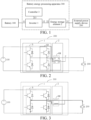
- FIG. 1 is a structural block diagram of a battery energy processing apparatus according to an exemplary embodiment.
- the battery energy processing apparatus 300 may include an inverter 1, an energy storage element 2, and a controller 3.
- a first terminal 11 of the inverter 1 is configured to be connected to a battery 100.
- a first terminal 21 of the energy storage element 2 is configured to be connected to an external power supply device 200, and a second terminal 22 of the energy storage element 2 is connected to a second terminal 12 of the inverter 1.
- the controller 3 is connected to a third terminal 13 of the inverter 1. In a first preset state, the controller 3 controls the inverter 1 to enable the energy storage element 2 to be charged and discharged by the battery 100 (for example, to be cyclically charged and discharged) so as to realize self-heating of the battery 100.
- the external power supply device 200 may be, for example, a charging pile or a storage battery.
- the cyclic charging and discharging means that charging and discharging are switched repeatedly at a specific frequency. Through the cyclic charging and discharging of the battery, the battery may generate heat, thereby realizing the self-heating of the battery.
- the first preset state is a battery self-heating state
- the second preset state is a battery charging state
- the battery energy processing apparatus includes the inverter, the energy storage element, and the controller.
- the inverter is connected to the battery and the energy storage element.
- the energy storage element is connected to the external power supply device.
- the controller controls the inverter to enable the energy storage element to be charged and discharged by the battery so as to realize the self-heating of the battery.
- electricity in the battery may be cycled between the battery and the energy storage element by using the energy storage element to realize the charging and discharging of the battery.
- the self-heating of the battery is realized to better maintain the temperature of the battery and increase the electrolyte activity and the electrochemical reaction rate of a lithium-ion battery, thereby ensuring the driving capability of a driving system of an electric vehicle.
- the self-heating of the battery has a small energy loss, uniform heat transfer, and high heating efficiency.
- at least part of the energy storage element and at least part of the inverter jointly form the adaptive voltage charger, and the controller controls the adaptive voltage charger to charge the battery.
- one battery energy processing apparatus is used for both battery charging and battery self-heating. In this way, the multifunctional reuse of the battery energy processing apparatus is realized, thereby reducing the costs and sizes of components.
- the inverter 1 includes N-phase bridge arms B, and the energy storage element 2 includes N coils KM.
- a quantity of at least one-phase bridge arm of the N-phase bridge arms B is the same as that of at least one coil of the N coils KM, and the at least one-phase bridge arm and the at least one coil jointly form the adaptive voltage charger.
- one-phase bridge arm of the N-phase bridge arms B and one coil of the N coils KM jointly form the adaptive voltage charger KB.
- first bus terminals of the N-phase bridge arms B are connected to a positive electrode of the battery 100, and second bus terminals of the N-phase bridge arms B are connected to a negative electrode of the battery 100 and a negative electrode of the external power supply device 200.
- Second terminals 22 of the N coils KM are connected to midpoints of the N-phase bridge arms B in a one-to-one correspondence, first terminals 21 of the N coils KM are connected together to form a neutral point P, and the neutral point P is configured to be connected to a positive electrode of the external power supply device 200.
- the controller 3 controls at least two-phase bridge arms of the N-phase bridge arms B to enable coils connected to the at least two-phase bridge arms of the N coils KM to be charged and discharged by the battery 100 so as to realize the self-heating of the battery 100.
- the controller 3 controls the N-phase bridge arms B to enable the N coils KM to be charged and discharged by the battery 100 so as to realize the self-heating of the battery 100.
- the N-phase bridge arms B and the N coils KM operate simultaneously, so that the heating efficiency can be maximized, thereby improving the battery self-heating effect.
- a specific process of heating the battery 100 by the battery energy processing apparatus 300 in FIG. 2 is as follows: the N coils KM are used as a current-limiting cushion apparatus, and a manner of turning on the N-phase bridge arms B is controlled, and a duty cycle of a bridge arm that is turned on is adjusted to control a loop current of the battery, to enable the internal resistance of the battery to generate heat to increase the temperature of the battery 100, thereby implementing the controlled temperature rise of the battery 100.
- At least one-phase bridge arm of the N-phase bridge arms B and at least one coil of the N coils KM jointly form the adaptive voltage charger, and the controller 3 controls an upper bridge arm of the at least one-phase bridge arm to be turned off and a lower bridge arm of the at least one-phase bridge arm to be turned on to charge the at least one coil.
- the N-phase bridge arms B include two bridge arms b1 and b2, and the N coils KM include two coils H1 and H2.
- One end of the coil H1 is connected to a midpoint of the bridge arm b1, and one end of the coil H2 is connected to a midpoint of the bridge arm b2.
- the controller 3 controls all upper bridge arms of the bridge arms b1 and b2 to be turned off, and controls all the lower bridge arms of the bridge arms b1 and b2 to be turned on.
- the controller 3 controls first switches K1 of the N first switches K1 correspondingly connected to at least two coils of the N coils KM to close, and controls at least two-phase bridge arms connected to the at least two coils of the N-phase bridge arms B to enable the at least two coils to be charged and discharged by the battery 100 so as to realize the self-heating of the battery 100.
- the controller 3 controls a first switch K1 of the N first switches K1 correspondingly connected to the at least one coil to close, and controls the adaptive voltage charger to charge the battery 100.
- the controller 3 may be further configured to: in the second preset state, detect whether every phase of bridge arm in the N-phase bridge arms B has a fault.
- a non-faulty bridge arm of the N-phase bridge arms B and a coil of the N coils KM connected to the non-faulty bridge arm jointly form the adaptive voltage charger, and the controller 3 controls a first switch K1 correspondingly connected to a coil connected to a faulty bridge arm of the N first switches K1 to open, controls a first switch K1 of the N first switches K1 correspondingly connected to a coil connected to a non-faulty bridge arm to close, and controls the adaptive voltage charger to charge the battery 100.
- a phase of bridge arm of the N-phase bridge arms B has a fault
- the faulty bridge arm can be turned off through a first switch K1 correspondingly connected thereto, to turn off a channel of the phase of bridge arm.
- Channels formed by other phases of bridge arms with normal functions are used to complete the charging of the battery, thereby improving the redundancy and fault tolerance performance of the battery energy processing apparatus 300.
- the energy storage element 2 further includes a first capacitor C1.
- a first terminal C11 of the first capacitor C1 is connected to the neutral point P and the positive electrode of the external power supply device 200, and a second terminal C12 of the first capacitor C1 is connected to the negative electrode of the battery 100 and the negative electrode of the external power supply device 200.
- the controller 3 controls at least one-phase bridge arm of the N-phase bridge arms B to enable the first capacitor C1 to be charged and discharged by the battery 100 so as to realize the self-heating of the battery 100.
- the controller 3 controls the adaptive voltage charger to charge the battery 100.
- a process of heating the battery 100 by using the N-phase bridge arms B, the N coils KM, and the first capacitor C1 in FIG. 7 in the first preset state is described below in detail with reference to FIG. 8 to FIG. 11 .
- the controller 3 may control all the lower bridge arms of the N-phase bridge arms B to be turned off, and control at least one upper bridge arm of the N-phase bridge arms B to be turned on.
- a current flows from the positive electrode of the battery 100, flows through the upper bridge arm that is turned on, a coil connected to the upper bridge arm that is turned on, and the first capacitor C1, and finally returns to the negative electrode of the battery 100.
- the battery 100 is in a discharging state, the first capacitor C1 receives energy of the coil connected to the upper bridge arm that is turned on, and the voltage keeps increasing, thereby realizing energy storage.
- the controller 3 may control all the upper bridge arms of the N-phase bridge arms B to be turned off, and control a lower bridge arm connected to a coil with a freewheeling current in the lower bridge arms of the N-phase bridge arms B to be turned on.
- a current flows from the coil with a freewheeling current, flows through the first capacitor C1 and the lower bridge arm that is turned on, and finally returns to the coil with a freewheeling current.
- the first capacitor C1 continues to receive energy of the coil, and the voltage keeps increasing.
- the first capacitor C1 automatically switches from receiving energy of the coils KM to releasing energy to the coils KM.
- a current flows from the first capacitor C1
- the voltage across the two terminals of the first capacitor C1 keeps decreasing.
- the controller 3 may control all the lower bridge arms of the N-phase bridge arms B to be turned off, and control at least one upper bridge arm of the N-phase bridge arms B to be turned on.
- a current flows from the first capacitor C1, flows through the coil connected to the upper bridge arm that is turned on, the upper bridge arm that is turned on, the positive electrode of the battery 100, and the negative electrode of the battery 100, and finally returns to the first capacitor C1.
- the battery 100 is in a charging state.
- the first capacitor C1 and the coil connected to the upper bridge arm that is turned on switch from releasing energy to the battery 100 to receiving energy of the battery 100.
- a flowing direction of the current becomes the flowing direction in the first process again, and the battery 100 starts discharging.
- the foregoing processes repeat continuously, so that quick cyclic charging/discharging can be performed between the first capacitor C1 and the battery 100. Due to the presence of the internal resistance of the battery, a large amount of heat is generated to quickly increase the temperature of the battery, thereby improving the heating efficiency of the battery.
- the apparatus further includes the N first switches K1.
- the first terminals K11 of the N first switches K1 are configured to be connected to the positive electrode of the external power supply device 200, and the second terminals K12 of the N first switches K1 are connected to the first terminals 21 of the N coils KM in a one-to-one correspondence.
- the controller 3 may be further configured to detect whether every phase of bridge arm in the N-phase bridge arms B has a fault.
- the controller 3 controls a first switch K1 of the N first switches K1 correspondingly connected to a coil connected to a faulty bridge arm to open, controls a first switch K1 of the N first switches K1 correspondingly connected to a coil connected to a non-faulty bridge arm to close, and controls a non-faulty bridge arm of the N-phase bridge arms B to enable the first capacitor C1 to be charged and discharged by the battery 100 so as to realize the self-heating of the battery 100.
- a phase of bridge arm of the N-phase bridge arms B has a fault
- the faulty bridge arm can be turned off through a first switch K1 correspondingly connected thereto, to turn off a channel of the phase of bridge arm.
- Channels formed by other phases of bridge arms with normal functions are used to complete the self-heating of the battery, thereby improving the redundancy and fault tolerance performance of the battery energy processing apparatus 300.
- the battery energy processing apparatus 300 may further include the N first switches K1 and the second switch K2.
- the energy storage element 2 further includes the first capacitor C1.
- the first terminals K11 of the N first switches K1 are configured to be connected to the positive electrode of the external power supply device 200, and the second terminals K12 of the N first switches K1 are connected to the first terminals 21 of the N coils KM in a one-to-one correspondence.
- a first terminal K21 of the second switch K2 is connected to the neutral point P, and a second terminal K22 of the second switch K2 is configured to be connected to the positive electrode of the external power supply device 200.
- the first terminal C11 of the first capacitor C1 is connected to the neutral point P and the positive electrode of the external power supply device 200, and the second terminal C12 of the first capacitor C1 is connected to the negative electrode of the battery 100 and the negative electrode of the external power supply device 200.
- the controller 3 controls first switches K1 of the N first switches K1 correspondingly connected to at least two coils of the N coils KM to close, controls the second switch K2 to open, and controls at least two-phase bridge arms connected to the at least two coils of the N-phase bridge arms B to enable the at least two coils to be charged and discharged by the battery 100 so as to realize the self-heating of the battery 100.
- the controller 3 controls a first switch K1 of the N first switches K1 correspondingly connected to a coil connected to at least one-phase bridge arm to close, controls the second switch K2 to close, and controls the at least one-phase bridge arm of the N-phase bridge arms B to enable the first capacitor C1 to be charged and discharged by the battery 100 so as to realize the self-heating of the battery 100.
- N 2
- a person skilled in the art should understand that the quantity of bridge arms and the quantity of coils in the figures are merely an example.
- the present disclosure further provides a battery energy processing method.
- the method includes:
- a first terminal of the inverter is configured to be connected to the battery, and a second terminal is connected to a second terminal of the energy storage element.
- a first terminal of the energy storage element is configured to be connected to an external power supply device.
- the self-heating of the battery is realized to better maintain the temperature of the battery and increase the electrolyte activity and the electrochemical reaction rate of a lithium-ion battery, thereby ensuring the driving capability of a driving system of an electric vehicle.
- the self-heating of the battery has a small energy loss, uniform heat transfer, and high heating efficiency.
- the foregoing battery energy processing apparatus may further reuse the energy storage element and the inverter to form the adaptive voltage charger, and control the inverter to charge the battery. In other words, one battery energy processing apparatus is used for both battery charging and battery self-heating. In this way, the multifunctional reuse of the battery energy processing apparatus is realized, thereby reducing the costs and sizes of components.
- the inverter includes at least two-phase bridge arms
- the energy storage element includes at least two coils
- a quantity of the at least two-phase bridge arms is the same as that of the at least two coils
- a quantity of at least one-phase bridge arm of the at least two-phase bridge arms is the same as that of at least one coil of the at least two coils
- the at least one-phase bridge arm and the at least one coil jointly form the adaptive voltage charger.
- first bus terminals of the at least two-phase bridge arms are connected to a positive electrode of the battery, and second bus terminals of the at least two-phase bridge arms are connected to a negative electrode of the battery and a negative electrode of the external power supply device.
- Second terminals of the at least two coils are connected to midpoints of the at least two-phase bridge arms, first terminals of the at least two coils are connected together to form a neutral point, and the neutral point is configured to be connected to a positive electrode of the external power supply device.
- the controlling an inverter to enable an energy storage element to be charged and discharged by a battery includes: controlling at least two-phase bridge arms of the at least two-phase bridge arms to enable coils connected to the at least two-phase bridge arms of the at least two coils to be charged and discharged by the battery so as to realize the self-heating of the battery.
- the making at least part of the energy storage element and at least part of the inverter jointly form an adaptive voltage charger, and controlling the adaptive voltage charger to charge the battery includes: making at least one-phase bridge arm of the at least two-phase bridge arms and at least one coil of the at least two coils jointly form the adaptive voltage charger, and controlling an upper bridge arm of the at least one-phase bridge arm to be turned off and a lower bridge arm of the at least one-phase bridge arm to be turned on to charge the at least one coil.
- the method further includes: when a voltage of the external power supply device is less than a voltage of the battery, in the second preset state, after the at least one coil is charged, controlling the lower bridge arm of the at least one-phase bridge arm to be turned off, and controlling a current to pass through a freewheeling diode of the upper bridge arm of the at least one-phase bridge arm to boost-charge the battery.
- controlling a current to pass through a freewheeling diode of the upper bridge arm of the at least one-phase bridge arm to boost-charge the battery includes: controlling an insulated gate bipolar transistor of the upper bridge arm of the at least one-phase bridge arm not to be turned on to control the current to pass through the freewheeling diode of the upper bridge arm of the at least one-phase bridge arm to boost-charge the battery.
- the method further includes: when the voltage of the external power supply device is not less than the voltage of the battery, in the second preset state, controlling insulated gate bipolar transistors of upper and lower bridge arms of the at least two-phase bridge arms not to be turned on to control currents to pass through freewheeling diodes of upper bridge arms of the at least two-phase bridge arms to directly charge the battery.
- first terminals of at least two first switches are configured to be connected to the positive electrode of the external power supply device, and second terminals of the at least two first switches are connected to the first terminals of the at least two coils in a one-to-one correspondence.
- the controlling at least two-phase bridge arms of the at least two-phase bridge arms to enable coils connected to the at least two-phase bridge arms of the at least two coils to be charged and discharged by the battery includes: controlling first switches of the at least two first switches correspondingly connected to at least two coils of the at least two coils to close, and controlling at least two-phase bridge arms connected to the at least two coils of the at least two-phase bridge arms to enable the at least two coils to be charged and discharged by the battery so as to realize the self-heating of the battery.
- the making at least one-phase bridge arm of the at least two-phase bridge arms and at least one coil of the at least two coils jointly form the adaptive voltage charger, and controlling an upper bridge arm of the at least one-phase bridge arm to be turned off and a lower bridge arm of the at least one-phase bridge arm to be turned on to charge the at least one coil includes: making at least one coil of the at least two coils and at least one-phase bridge arm correspondingly connected to the at least one coil jointly form the adaptive voltage charger, controlling a first switch of the at least two first switches correspondingly connected to the at least one coil to close, and controlling the adaptive voltage charger to charge the battery.
- first terminals of at least two first switches are configured to be connected to the positive electrode of the external power supply device, and second terminals of the at least two first switches are connected to the first terminals of the at least two coils in a one-to-one correspondence.
- the energy storage element further includes a first capacitor.
- a first terminal of the first capacitor is connected to the neutral point and the positive electrode of the external power supply device, and a second terminal of the first capacitor is connected to the negative electrode of the battery and the negative electrode of the external power supply device.
- the controlling an inverter to enable an energy storage element to be charged and discharged by a battery includes: controlling at least one-phase bridge arm of the at least two-phase bridge arms to enable the first capacitor to be charged and discharged by the battery so as to realize the self-heating of the battery.
- the making at least part of the energy storage element and at least part of the inverter jointly form an adaptive voltage charger, and controlling the adaptive voltage charger to charge the battery includes: making at least one coil of the at least two coils KM and at least one-phase bridge arm correspondingly connected to the at least one coil jointly form the adaptive voltage charger, and controlling the adaptive voltage charger to charge the battery.
- first terminals of at least two first switches are configured to be connected to the positive electrode of the external power supply device, and second terminals of the at least two first switches are connected to the first terminals of the at least two coils in a one-to-one correspondence.
- the controlling an inverter to enable an energy storage element to be charged and discharged by a battery includes: controlling a first switch of the at least two first switches correspondingly connected to a coil connected to a faulty bridge arm to open, controlling a first switch of the at least two first switches correspondingly connected to a coil connected to a non-faulty bridge arm to close, and controlling a non-faulty bridge arm of the at least two-phase bridge arms to enable the first capacitor to be charged and discharged by the battery so as to realize the self-heating of the battery.
- first terminals of at least two first switches are configured to be connected to the positive electrode of the external power supply device, and second terminals of the at least two first switches are connected to the first terminals of the at least two coils in a one-to-one correspondence.
- the energy storage element further includes the first capacitor.
- the first terminal of the first capacitor is connected to the neutral point and the positive electrode of the external power supply device, and the second terminal of the first capacitor is connected to the negative electrode of the battery and the negative electrode of the external power supply device.
- the controlling an inverter to enable an energy storage element to be charged and discharged by a battery includes:
- the present disclosure further provides a vehicle, including a battery and the foregoing battery energy processing apparatus provided in the present disclosure.
Landscapes
- Engineering & Computer Science (AREA)
- Power Engineering (AREA)
- Mechanical Engineering (AREA)
- Transportation (AREA)
- General Chemical & Material Sciences (AREA)
- Electrochemistry (AREA)
- Chemical Kinetics & Catalysis (AREA)
- Chemical & Material Sciences (AREA)
- Manufacturing & Machinery (AREA)
- Life Sciences & Earth Sciences (AREA)
- Sustainable Development (AREA)
- Sustainable Energy (AREA)
- Automation & Control Theory (AREA)
- Charge And Discharge Circuits For Batteries Or The Like (AREA)
- Secondary Cells (AREA)
Abstract
Description
- The present disclosure claims priority to and benefits of
Chinese Patent Application No. 202210583659.9, filed on May 25, 2022 - The present disclosure relates to the field of vehicle technologies, and specifically, to a battery energy processing apparatus and a vehicle.
- A power battery equipped on an electric vehicle has severe performance attenuation during charging and discharging in a low-temperature environment, and as a result the capability of a driving system or a charging system is restricted in the low-temperature environment, which severely degrades user experience.
- To reduce restrictions of a low-temperature environment on a power battery, some heating solutions for a power battery are proposed. In addition, a fast charge function for a power battery is also an essential function for a new energy vehicle.
- Therefore, it is presently urgent to seek for a technical solution that gives consideration to both charging and heating.
- In order to overcome the problems in the related art, the present disclosure provides a battery energy processing apparatus and a vehicle.
- In order to realize the objective, on a first aspect, the present disclosure provides a battery energy processing apparatus, including:
- an inverter, a first terminal of the inverter being configured to be connected to a battery;
- an energy storage element, a first terminal of the energy storage element being configured to be connected to an external power supply device, a second terminal of the energy storage element being connected to a second terminal of the first terminal of the inverter; and
- a controller, the controller being connected to a third terminal of the inverter.
- In a first preset state, the controller controls the inverter to enable the energy storage element to be charged and discharged by the battery so as to realize self-heating of the battery.
- In a second preset state, at least part of the energy storage element and at least part of the inverter jointly form an adaptive voltage charger, and the controller controls the adaptive voltage charger to charge the battery.
- Optionally, the inverter includes at least two-phase bridge arms, the energy storage element includes at least two coils, a quantity of the at least two-phase bridge arms is the same as that of the at least two coils, a quantity of at least one-phase bridge arm of the at least two-phase bridge arms is the same as that of at least one coil of the at least two coils, and the at least one-phase bridge arm and the at least one coil jointly form the adaptive voltage charger.
- Optionally, first bus terminals of the at least two-phase bridge arms are connected to a positive electrode of the battery, and second bus terminals of the at least two-phase bridge arms are connected to a negative electrode of the battery and a negative electrode of the external power supply device.
- Second terminals of the at least two coils are connected to midpoints of the at least two-phase bridge arms, first terminals of the at least two coils are connected together to form a neutral point, and the neutral point is configured to be connected to a positive electrode of the external power supply device.
- Optionally, in the first preset state, the controller controls at least two-phase bridge arms of the at least two-phase bridge arms to enable coils connected to the at least two-phase bridge arms of the at least two coils to be charged and discharged by the battery so as to realize the self-heating of the battery.
- Optionally, when a voltage of the external power supply device is less than a voltage of the battery, in the second preset state, at least one-phase bridge arm of the at least two-phase bridge arms and at least one coil of the at least two coils jointly form the adaptive voltage charger, and the controller controls an upper bridge arm of the at least one-phase bridge arm to be turned off and a lower bridge arm of the at least one-phase bridge arm to be turned on to charge the at least one coil.
- Optionally, when the voltage of the external power supply device is less than the voltage of the battery, in the second preset state, after the at least one coil is charged, the controller further controls the lower bridge arm of the at least one-phase bridge arm to be turned off and controls a current to pass through a freewheeling diode of the upper bridge arm of the at least one-phase bridge arm to boost-charge the battery.
- Optionally, the controlling the current to pass through the freewheeling diode of the upper bridge arm of the at least one-phase bridge arm to boost-charge the battery includes: controlling an insulated gate bipolar transistor of the upper bridge arm of the at least one-phase bridge arm not to be turned on to control the current to pass through the freewheeling diode of the upper bridge arm of the at least one-phase bridge arm to boost-charge the battery.
- Optionally, when the voltage of the external power supply device is not less than the voltage of the battery, in the second preset state, the controller controls insulated gate bipolar transistors of upper and lower bridge arms of the at least two-phase bridge arms not to be turned on to control currents to pass through freewheeling diodes of upper bridge arms of the at least two-phase bridge arms to directly charge the battery.
- Optionally, the apparatus further includes: at least two first switches, first terminals of the at least two first switches being configured to be connected to the positive electrode of the external power supply device, and second terminals of the at least two first switches being connected to the first terminals of the at least two coils in a one-to-one correspondence.
- Optionally, in the first preset state, the controller controls first switches of the at least two first switches correspondingly connected to at least two coils of the at least two coils to close, and controls at least two-phase bridge arms connected to the at least two coils of the at least two-phase bridge arms to enable the at least two coils to be charged and discharged by the battery so as to realize the self-heating of the battery.
- In the second preset state, at least one coil of the at least two coils and at least one-phase bridge arm correspondingly connected to the at least one coil jointly form the adaptive voltage charger, and the controller controls a first switch of the at least two first switches correspondingly connected to the at least one coil to close, and controls the adaptive voltage charger to charge the battery.
- Optionally, in the second preset state, a non-faulty bridge arm of the at least two-phase bridge arms and a coil of the at least two coils connected to the non-faulty bridge arm jointly form the adaptive voltage charger, and the controller controls a first switch of the at least two first switches correspondingly connected to a coil connected to a faulty bridge arm to open, controls a first switch of the at least two first switches correspondingly connected to a coil connected to a non-faulty bridge arm to close, and controls the adaptive voltage charger to charge the battery.
- Optionally, the energy storage element further includes a first capacitor.
a first terminal of the first capacitor is connected to the neutral point and the positive electrode of the external power supply device, and a second terminal of the first capacitor is connected to the negative electrode of the battery and the negative electrode of the external power supply device. - Optionally, in the first preset state, the controller controls at least one-phase bridge arm of the at least two-phase bridge arms to enable the first capacitor to be charged and discharged by the battery so as to realize the self-heating of the battery.
- In the second preset state, at least one coil of the at least two coils and at least one-phase bridge arm correspondingly connected to the at least one coil jointly form the adaptive voltage charger, and the controller controls the adaptive voltage charger to charge the battery.
- Optionally, the apparatus further includes:
the at least two first switches, the first terminals of the at least two first switches being configured to be connected to the positive electrode of the external power supply device, and the second terminals of the at least two first switches being connected to the first terminals of the at least two coils in a one-to-one correspondence. - In the first preset state, the controller controls a first switch of the at least two first switches correspondingly connected to a coil connected to a faulty bridge arm to open, controls a first switch of the at least two first switches correspondingly connected to a coil connected to a non-faulty bridge arm to close, and controls a non-faulty bridge arm of the at least two-phase bridge arms to enable the first capacitor to be charged and discharged by the battery so as to realize the self-heating of the battery.
- Optionally, the apparatus further includes:
- the at least two first switches, the first terminals of the at least two first switches being configured to be connected to the positive electrode of the external power supply device, and the second terminals of the at least two first switches being connected to the first terminals of the at least two coils in a one-to-one correspondence; and
- a second switch, a first terminal of the second switch being connected to the neutral point, and a second terminal of the second switch being configured to be connected to the positive electrode of the external power supply device.
- The energy storage element further includes the first capacitor. The first terminal of the first capacitor is connected to the neutral point and the positive electrode of the external power supply device, and the second terminal of the first capacitor is connected to the negative electrode of the battery and the negative electrode of the external power supply device.
- In the first preset state, in response to receiving a first control instruction configured for indicating to perform inductive self-heating on the battery, the controller controls first switches of the at least two first switches correspondingly connected to at least two coils of the at least two coils to close, controls the second switch to open, and controls at least two-phase bridge arms connected to the at least two coils of the at least two-phase bridge arms to enable the at least two coils to be charged and discharged by the battery so as to realize the self-heating of the battery.
- In the first preset state, in response to receiving a second control instruction configured for indicating to perform capacitive self-heating on the battery, the controller controls a first switch of the at least two first switches correspondingly connected to a coil connected to at least one-phase bridge arm to close, controls the second switch to close, and controls the at least one-phase bridge arm of the at least two-phase bridge arms to enable the first capacitor to be charged and discharged by the battery so as to realize the self-heating of the battery.
- On a second aspect, the present disclosure provides a vehicle, including:
- a battery; and
- the battery energy processing apparatus according to the first aspect of the present disclosure.
- In the foregoing technical solution, the battery energy processing apparatus includes the inverter, the energy storage element, and the controller. The inverter is connected to the battery and the energy storage element. The energy storage element is connected to the external power supply device. In the first preset state, the controller controls the inverter to enable the energy storage element to be charged and discharged by the battery so as to realize the self-heating of the battery. In this way, in the first preset state, electricity in the battery may be cycled between the battery and the energy storage element by using the energy storage element to realize the charging and discharging of the battery. In this way, the self-heating of the battery is realized to better maintain the temperature of the battery and increase the electrolyte activity and the electrochemical reaction rate of a lithium-ion battery, thereby ensuring the driving capability of a driving system of an electric vehicle. In addition, the self-heating of the battery has a small energy loss, uniform heat transfer, and high heating efficiency. In addition, in the second preset state, at least part of the energy storage element and at least part of the inverter jointly form the adaptive voltage charger, and the controller controls the adaptive voltage charger to charge the battery. In other words, one battery energy processing apparatus is used for both battery charging and battery self-heating. In this way, the multifunctional reuse of the battery energy processing apparatus is realized, thereby reducing the costs and sizes of components.
- Other features and advantages of the present disclosure will be described in detail in the following detailed description.
- The accompanying drawings are provided to further understand the present disclosure, and they constitute a part of the specification. The accompanying drawings, along with the specific implementations, are used to explain the present disclosure, and pose no limitation on the present disclosure. In the figures:
-
FIG. 1 is a structural block diagram of a battery energy processing apparatus according to an exemplary embodiment; -
FIG. 2 is a circuit topology diagram of a battery energy processing apparatus according to an exemplary embodiment; -
FIG. 3 andFIG. 4 are schematic diagrams of a working principle of boost-charging a battery in a second preset state according to an exemplary embodiment; -
FIG. 5 is a circuit topology diagram of a battery energy processing apparatus according to another exemplary embodiment; -
FIG. 6 is a circuit topology diagram of a battery energy processing apparatus according to another exemplary embodiment; -
FIG. 7 is a circuit topology diagram of a battery energy processing apparatus according to another exemplary embodiment; -
FIG. 8 to FIG. 11 are schematic diagrams of a working principle of heating a battery by the battery energy processing apparatus shown inFIG. 7 in a first preset state according to an exemplary embodiment; -
FIG. 12 is a circuit topology diagram of a battery energy processing apparatus according to another exemplary embodiment; -
FIG. 13 is a circuit topology diagram of a battery energy processing apparatus according to another exemplary embodiment; - The following describes the specific implementations of the present disclosure in detail with reference to the accompanying drawings. It should be understood that the specific implementations described herein are merely used to describe and explain the present disclosure, but are not intended to limit the present disclosure.
- It should be noted that all actions of obtaining a signal, information, or data in the present disclosure are performed under the premise of complying with data protection regulations and policies corresponding to countries where the actions are located and with authorization given by an owner of a corresponding apparatus.
-
FIG. 1 is a structural block diagram of a battery energy processing apparatus according to an exemplary embodiment. As shown inFIG. 1 , the batteryenergy processing apparatus 300 may include aninverter 1, anenergy storage element 2, and acontroller 3. - A
first terminal 11 of theinverter 1 is configured to be connected to abattery 100. Afirst terminal 21 of theenergy storage element 2 is configured to be connected to an externalpower supply device 200, and asecond terminal 22 of theenergy storage element 2 is connected to asecond terminal 12 of theinverter 1. Thecontroller 3 is connected to athird terminal 13 of theinverter 1. In a first preset state, thecontroller 3 controls theinverter 1 to enable theenergy storage element 2 to be charged and discharged by the battery 100 (for example, to be cyclically charged and discharged) so as to realize self-heating of thebattery 100. In a second preset state, at least part of theenergy storage element 2 and at least part of theinverter 1 jointly form an adaptive voltage charger, and thecontroller 3 controls the adaptive voltage charger to charge thebattery 100. The externalpower supply device 200 may be, for example, a charging pile or a storage battery. - The cyclic charging and discharging means that charging and discharging are switched repeatedly at a specific frequency. Through the cyclic charging and discharging of the battery, the battery may generate heat, thereby realizing the self-heating of the battery.
- In the present disclosure, the first preset state is a battery self-heating state, and the second preset state is a battery charging state.
- In the foregoing technical solution, the battery energy processing apparatus includes the inverter, the energy storage element, and the controller. The inverter is connected to the battery and the energy storage element. The energy storage element is connected to the external power supply device. In the first preset state, the controller controls the inverter to enable the energy storage element to be charged and discharged by the battery so as to realize the self-heating of the battery. In this way, in the first preset state, electricity in the battery may be cycled between the battery and the energy storage element by using the energy storage element to realize the charging and discharging of the battery. In this way, the self-heating of the battery is realized to better maintain the temperature of the battery and increase the electrolyte activity and the electrochemical reaction rate of a lithium-ion battery, thereby ensuring the driving capability of a driving system of an electric vehicle. In addition, the self-heating of the battery has a small energy loss, uniform heat transfer, and high heating efficiency. In addition, in the second preset state, at least part of the energy storage element and at least part of the inverter jointly form the adaptive voltage charger, and the controller controls the adaptive voltage charger to charge the battery. In other words, one battery energy processing apparatus is used for both battery charging and battery self-heating. In this way, the multifunctional reuse of the battery energy processing apparatus is realized, thereby reducing the costs and sizes of components.
- As shown in
FIG. 2 , theinverter 1 includes N-phase bridge arms B, and theenergy storage element 2 includes N coils KM. A quantity of at least one-phase bridge arm of the N-phase bridge arms B is the same as that of at least one coil of the N coils KM, and the at least one-phase bridge arm and the at least one coil jointly form the adaptive voltage charger. - For example, as shown in
FIG. 2 , one-phase bridge arm of the N-phase bridge arms B and one coil of the N coils KM jointly form the adaptive voltage charger KB. - As shown in
FIG. 2 , first bus terminals of the N-phase bridge arms B are connected to a positive electrode of thebattery 100, and second bus terminals of the N-phase bridge arms B are connected to a negative electrode of thebattery 100 and a negative electrode of the externalpower supply device 200.Second terminals 22 of the N coils KM are connected to midpoints of the N-phase bridge arms B in a one-to-one correspondence,first terminals 21 of the N coils KM are connected together to form a neutral point P, and the neutral point P is configured to be connected to a positive electrode of the externalpower supply device 200. - In this case, in the first preset state, the
controller 3 controls at least two-phase bridge arms of the N-phase bridge arms B to enable coils connected to the at least two-phase bridge arms of the N coils KM to be charged and discharged by thebattery 100 so as to realize the self-heating of thebattery 100. - When a voltage of the external
power supply device 200 is less than a voltage of thebattery 100, in the second preset state, at least one-phase bridge arm of the N-phase bridge arms B and at least one coil of the N coils KM jointly form the adaptive voltage charger, and thecontroller 3 controls an upper bridge arm of the at least one-phase bridge arm to be turned off and a lower bridge arm of the at least one-phase bridge arm to be turned on to charge the at least one coil. - Optionally, in the first preset state, the
controller 3 controls the N-phase bridge arms B to enable the N coils KM to be charged and discharged by thebattery 100 so as to realize the self-heating of thebattery 100. In this way, the N-phase bridge arms B and the N coils KM operate simultaneously, so that the heating efficiency can be maximized, thereby improving the battery self-heating effect. - In the second preset state, the N coils KM and the N-phase bridge arms B jointly form the adaptive voltage charger, and the
controller 3 controls the adaptive voltage charger to charge thebattery 100. In this way, the N-phase bridge arms B and the N coils operate simultaneously, so that the charging efficiency can be maximized, thereby improving the battery charging efficiency. - Although an example of N = 2 is used in
FIG. 2 , a person skilled in the art should understand that the quantity of bridge arms and the quantity of coils inFIG. 2 are merely an example. - In the first preset state, a specific process of heating the
battery 100 by the batteryenergy processing apparatus 300 inFIG. 2 is as follows: the N coils KM are used as a current-limiting cushion apparatus, and a manner of turning on the N-phase bridge arms B is controlled, and a duty cycle of a bridge arm that is turned on is adjusted to control a loop current of the battery, to enable the internal resistance of the battery to generate heat to increase the temperature of thebattery 100, thereby implementing the controlled temperature rise of thebattery 100. - When a voltage of the external
power supply device 200 is less than a voltage of thebattery 100, in the second preset state, at least one-phase bridge arm of the N-phase bridge arms B and at least one coil of the N coils KM jointly form the adaptive voltage charger, and thecontroller 3 controls an upper bridge arm of the at least one-phase bridge arm to be turned off and a lower bridge arm of the at least one-phase bridge arm to be turned on to charge the at least one coil. - In the second preset state, at least one-phase bridge arm of the N-phase bridge arms B charges the
battery 100. Thebattery 100 may be boost-charged or may be directly charged. A charging mode to use may be determined according to the voltage of thebattery 100 and the voltage of the externalpower supply device 200. - Specifically, the
controller 3 is further configured to detect whether the voltage of the externalpower supply device 200 is less than the voltage of thebattery 100. When a voltage of the externalpower supply device 200 is less than a voltage of thebattery 100, in the second preset state, at least one-phase bridge arm of the N-phase bridge arms B and at least one coil of the N coils KM jointly form the adaptive voltage charger, and thecontroller 3 controls an upper bridge arm of the at least one-phase bridge arm to be turned off and a lower bridge arm of the at least one-phase bridge arm to be turned on to charge the at least one coil, to charge a coil (i.e., at least one coil in the adaptive voltage charger) connected to the lower bridge arm that is turned on of the N coils KM. Next, thecontroller 3 further controls the lower bridge arm of the at least one-phase bridge arm correspondingly connected to the at least one coil to be turned off and controls a current to pass through a freewheeling diode of the upper bridge arm of the at least one-phase bridge arm to boost-charge thebattery 100. - In an implementation, the controlling the current to pass through the freewheeling diode of the upper bridge arm of the at least one-phase bridge arm to boost-charge the
battery 100 includes: controlling an insulated gate bipolar transistor of the upper bridge arm of the at least one-phase bridge arm not to be turned on to control the current to pass through the freewheeling diode of the upper bridge arm of the at least one-phase bridge arm to boost-charge thebattery 100. - When the voltage of the external
power supply device 200 is not less than the voltage of thebattery 100, in the second preset state, thecontroller 3 controls insulated gate bipolar transistors of upper and lower bridge arms of the N-phase bridge arms B not to be turned on to control currents to pass through freewheeling diodes of upper bridge arms of the N-phase bridge arms B to directly charge thebattery 100. - In this way, adaptive voltage charging may be automatically performed according to the voltage of the external
power supply device 200 and the voltage of thebattery 100. In this way, both a high-voltage external power supply device and a low-voltage external power supply device can realize the charging of a high-voltage battery through the batteryenergy processing apparatus 300 without additionally configuring a boost device. - A working principle of boost-charging the
battery 100 in the second preset state is described below in detail with reference toFIG. 3 andFIG. 4 . - In
FIG. 3 , thecontroller 3 controls all upper bridge arms of the N-phase bridge arms B to be turned off and controls at least one-phase lower bridge arm of the N-phase bridge arms B to be turned on. In this case, a current flows from the positive electrode of the externalpower supply device 200 and sequentially flows through a coil of the N coils KM connected to the lower bridge arm that is turned on and the lower bridge arm that is turned on of the N-phase bridge arms B to return to the negative electrode of the externalpower supply device 200. In this way, the coil connected to the lower bridge arm that is turned on of the N coils KM can be charged. In addition, a charging current can be controlled by controlling a turn-on quantity and a turn-on duty cycle of lower bridge arms, thereby controlling a charging power. - In an example, it is assumed that the N-phase bridge arms B include two bridge arms b1 and b2, and the N coils KM include two coils H1 and H2. One end of the coil H1 is connected to a midpoint of the bridge arm b1, and one end of the coil H2 is connected to a midpoint of the bridge arm b2. Next, the
controller 3 controls all upper bridge arms of the bridge arms b1 and b2 to be turned off, and controls all the lower bridge arms of the bridge arms b1 and b2 to be turned on. The positive electrode of the externalpower supply device 200, the N coils KM (i.e., the coils H1 and H2), all lower bridge arms (i.e., the lower bridge arms of the bridge arms b1 and b2) of the N-phase bridge arms B, and the negative electrode of the externalpower supply device 200 form a loop for charging the N coils KM. - Next, in
FIG. 4 , thecontroller 3 controls all the lower bridge arms of the N-phase bridge arms B to be turned off. In this case, a current flows from the positive electrode of the externalpower supply device 200 and sequentially flows through the N coils KM, freewheeling diodes of all the upper bridge arms of the N-phase bridge arms B, the positive electrode of thebattery 100, and the negative electrode of thebattery 100 to return to the negative electrode of the externalpower supply device 200. In this way, energy of the externalpower supply device 200 and the N coils KM can be transferred to thebattery 100, to realize that the N coils KM and the externalpower supply device 200 charge thebattery 100 simultaneously, i.e., realize boost-charging of thebattery 100. - The foregoing example is still used. In the foregoing example, all the lower bridge arms of the bridge arms b1 and b2 are turned on. Therefore, in this case, all the lower bridge arms of the N-phase bridge arms B (i.e., all the upper bridge arms of the bridge arms b1 and b2) are turned off. The positive electrode of the external
power supply device 200, the N coils KM (i.e., the coils H1 and H2), the freewheeling diodes of all the upper bridge arms of the N-phase bridge arms B (i.e., the upper bridge arms of the bridge arms b1 and b2), thebattery 100, and the negative electrode of the externalpower supply device 200 form a loop that transfers energy in the N coils KM and energy received by the external power supply device to thebattery 100, i.e., the N coils KM and the externalpower supply device 200 charge thebattery 100. - Therefore, cyclic work in the states in
FIG. 3 andFIG. 4 is realized by controlling an upper bridge arm of the at least one-phase bridge arm of the N-phase bridge arms B to be turned off and a lower bridge arm of the at least one-phase bridge arm to be alternately turned on or off, to complete the boost-charging of thebattery 100. - A working principle of directly charging the
battery 100 in the second preset state is described below in detail with reference toFIG. 4 . - In a case that the voltage of the external
power supply device 200 is not less than the voltage of thebattery 100, it is not necessary to boost-charge the external power supply device. In this case, as shown inFIG. 4 , thecontroller 3 may control all the lower bridge arms of the N-phase bridge arms B to be turned off. In this case, a current flows from the positive electrode of the externalpower supply device 200 and sequentially flows through the N coils KM, freewheeling diodes of all the upper bridge arms of the N-phase bridge arms B, the positive electrode of thebattery 100, and the negative electrode of thebattery 100 to return to the negative electrode of the externalpower supply device 200. In this way, energy of the externalpower supply device 200 can be transferred to thebattery 100, to realize that the externalpower supply device 200 charges thebattery 100, i.e., realize direct charging of thebattery 100. - In an embodiment, the N coils KM are motor windings (for example, motor windings of a driving motor), and the N-phase bridge arms B are bridge arm converters. That is, existing motor windings and bridge arm converters on a vehicle are reused, so that different functions can be realized as required. For example, when the battery requires self-heating or charging, the N coils KM and the N-phase bridge arms B can be used in various self-heating procedures described in the present disclosure. When the vehicle needs to be driven, the N coils KM and the N-phase bridge arms B can be switched to control the bridge arms B to enable the motors corresponding to the motor windings to output a power, thereby driving the vehicle. In this way, the motor windings and the bridge arm converters of the vehicle can be reused to realize different functions as required, and the costs of the vehicle are reduced.
- In addition, as shown in
FIG. 5 , the batteryenergy processing apparatus 300 may further include a second capacitor C2. A first terminal C21 of the second capacitor C2 is connected to the positive electrode of thebattery 100 and the first bus terminals of the N-phase bridge arms B, and a second terminal C22 of the second capacitor C2 is connected to the negative electrode of thebattery 100 and the second bus terminals of the N-phase bridge arms B. The second capacitor C2 has a voltage stabilization effect, so that an impact on the components in the batteryenergy processing apparatus 300 by a spike generated at the instant when the batteryenergy processing apparatus 300 and thebattery 100 or the externalpower supply device 200 are turned on can be avoided. - In addition, the battery
energy processing apparatus 300 may further include a third switch K3 and a fourth switch K4 (neither is shown in the figures). A first terminal of the third switch K3 is connected to the neutral point, and a second terminal of the third switch K3 is connected to the positive electrode of the externalpower supply device 200. A first terminal of the fourth switch K4 is connected to the negative electrode of thebattery 100, and a second terminal of the fourth switch K4 is connected to the negative electrode of the externalpower supply device 200. - In this case, in the first preset state, the
controller 3 controls both the third switch K3 and the fourth switch K4 to open, and controls at least two-phase bridge arms of the N-phase bridge arms B to enable coils connected to the at least two-phase bridge arms of the N coils KM to be charged and discharged by thebattery 100 so as to realize the self-heating of thebattery 100; and in the second preset state, controls both the third switch K3 and the fourth switch K4 to close, and controls the adaptive voltage charger to charge thebattery 100. - As shown in
FIG. 6 , the batteryenergy processing apparatus 300 further includes N first switches K1. First terminals K11 of the N first switches K1 are configured to be connected to the positive electrode of the externalpower supply device 200, and second terminals K12 of the N first switches K1 are connected to thefirst terminals 21 of the N coils KM in a one-to-one correspondence. - In this case, in the first preset state, the
controller 3 controls first switches K1 of the N first switches K1 correspondingly connected to at least two coils of the N coils KM to close, and controls at least two-phase bridge arms connected to the at least two coils of the N-phase bridge arms B to enable the at least two coils to be charged and discharged by thebattery 100 so as to realize the self-heating of thebattery 100. In the second preset state, at least one coil of the N coils KM and at least one-phase bridge arm correspondingly connected to the at least one coil jointly form the adaptive voltage charger, and thecontroller 3 controls a first switch K1 of the N first switches K1 correspondingly connected to the at least one coil to close, and controls the adaptive voltage charger to charge thebattery 100. - In addition, for the battery
energy processing apparatus 300 shown inFIG. 6 , thecontroller 3 may be further configured to: in the second preset state, detect whether every phase of bridge arm in the N-phase bridge arms B has a fault. In the second preset state, a non-faulty bridge arm of the N-phase bridge arms B and a coil of the N coils KM connected to the non-faulty bridge arm jointly form the adaptive voltage charger, and thecontroller 3 controls a first switch K1 correspondingly connected to a coil connected to a faulty bridge arm of the N first switches K1 to open, controls a first switch K1 of the N first switches K1 correspondingly connected to a coil connected to a non-faulty bridge arm to close, and controls the adaptive voltage charger to charge thebattery 100. In this way, if a phase of bridge arm of the N-phase bridge arms B has a fault, the faulty bridge arm can be turned off through a first switch K1 correspondingly connected thereto, to turn off a channel of the phase of bridge arm. Channels formed by other phases of bridge arms with normal functions are used to complete the charging of the battery, thereby improving the redundancy and fault tolerance performance of the batteryenergy processing apparatus 300. - As shown in
FIG. 7 , theenergy storage element 2 further includes a first capacitor C1. A first terminal C11 of the first capacitor C1 is connected to the neutral point P and the positive electrode of the externalpower supply device 200, and a second terminal C12 of the first capacitor C1 is connected to the negative electrode of thebattery 100 and the negative electrode of the externalpower supply device 200. - In this case, in the first preset state, the
controller 3 controls at least one-phase bridge arm of the N-phase bridge arms B to enable the first capacitor C1 to be charged and discharged by thebattery 100 so as to realize the self-heating of thebattery 100. In the second preset state, at least one coil of the N coils KM and at least one-phase bridge arm correspondingly connected to the at least one coil jointly form the adaptive voltage charger, and thecontroller 3 controls the adaptive voltage charger to charge thebattery 100. - A process of heating the
battery 100 by using the N-phase bridge arms B, the N coils KM, and the first capacitor C1 inFIG. 7 in the first preset state is described below in detail with reference toFIG. 8 to FIG. 11 . - First, as shown in
FIG. 8 , in a first process, thecontroller 3 may control all the lower bridge arms of the N-phase bridge arms B to be turned off, and control at least one upper bridge arm of the N-phase bridge arms B to be turned on. In this case, a current flows from the positive electrode of thebattery 100, flows through the upper bridge arm that is turned on, a coil connected to the upper bridge arm that is turned on, and the first capacitor C1, and finally returns to the negative electrode of thebattery 100. In the process, thebattery 100 is in a discharging state, the first capacitor C1 receives energy of the coil connected to the upper bridge arm that is turned on, and the voltage keeps increasing, thereby realizing energy storage. - Next, as shown in
FIG. 9 , in a second process, thecontroller 3 may control all the upper bridge arms of the N-phase bridge arms B to be turned off, and control a lower bridge arm connected to a coil with a freewheeling current in the lower bridge arms of the N-phase bridge arms B to be turned on. In this case, a current flows from the coil with a freewheeling current, flows through the first capacitor C1 and the lower bridge arm that is turned on, and finally returns to the coil with a freewheeling current. In the process, due to the freewheeling effect of the coil, the first capacitor C1 continues to receive energy of the coil, and the voltage keeps increasing. - As shown in
FIG. 10 , in a third process, as a voltage across the two terminals of the first capacitor C1 keeps increasing, the first capacitor C1 automatically switches from receiving energy of the coils KM to releasing energy to the coils KM. In this case, a current flows from the first capacitor C1, flows through the coil connected to the lower bridge arm that is turned on and the lower bridge arm that is turned on, and finally returns to the first capacitor C1. In the process, the voltage across the two terminals of the first capacitor C1 keeps decreasing. - Next, as shown in
FIG. 11 , in a fourth process, thecontroller 3 may control all the lower bridge arms of the N-phase bridge arms B to be turned off, and control at least one upper bridge arm of the N-phase bridge arms B to be turned on. In this case, a current flows from the first capacitor C1, flows through the coil connected to the upper bridge arm that is turned on, the upper bridge arm that is turned on, the positive electrode of thebattery 100, and the negative electrode of thebattery 100, and finally returns to the first capacitor C1. In the process, thebattery 100 is in a charging state. - As the voltage across the two terminals of the first capacitor C1 keeps decreasing, the first capacitor C1 and the coil connected to the upper bridge arm that is turned on switch from releasing energy to the
battery 100 to receiving energy of thebattery 100. In this case, a flowing direction of the current becomes the flowing direction in the first process again, and thebattery 100 starts discharging. - The foregoing processes repeat continuously, so that quick cyclic charging/discharging can be performed between the first capacitor C1 and the
battery 100. Due to the presence of the internal resistance of the battery, a large amount of heat is generated to quickly increase the temperature of the battery, thereby improving the heating efficiency of the battery. - As shown in
FIG. 12 , the apparatus further includes the N first switches K1. The first terminals K11 of the N first switches K1 are configured to be connected to the positive electrode of the externalpower supply device 200, and the second terminals K12 of the N first switches K1 are connected to thefirst terminals 21 of the N coils KM in a one-to-one correspondence. In this case, thecontroller 3 may be further configured to detect whether every phase of bridge arm in the N-phase bridge arms B has a fault. In this case, in the first preset state, thecontroller 3 controls a first switch K1 of the N first switches K1 correspondingly connected to a coil connected to a faulty bridge arm to open, controls a first switch K1 of the N first switches K1 correspondingly connected to a coil connected to a non-faulty bridge arm to close, and controls a non-faulty bridge arm of the N-phase bridge arms B to enable the first capacitor C1 to be charged and discharged by thebattery 100 so as to realize the self-heating of thebattery 100. - In this way, if a phase of bridge arm of the N-phase bridge arms B has a fault, the faulty bridge arm can be turned off through a first switch K1 correspondingly connected thereto, to turn off a channel of the phase of bridge arm. Channels formed by other phases of bridge arms with normal functions are used to complete the self-heating of the battery, thereby improving the redundancy and fault tolerance performance of the battery
energy processing apparatus 300. - As shown in
FIG. 13 , the batteryenergy processing apparatus 300 may further include the N first switches K1 and the second switch K2. Theenergy storage element 2 further includes the first capacitor C1. The first terminals K11 of the N first switches K1 are configured to be connected to the positive electrode of the externalpower supply device 200, and the second terminals K12 of the N first switches K1 are connected to thefirst terminals 21 of the N coils KM in a one-to-one correspondence. A first terminal K21 of the second switch K2 is connected to the neutral point P, and a second terminal K22 of the second switch K2 is configured to be connected to the positive electrode of the externalpower supply device 200. The first terminal C11 of the first capacitor C1 is connected to the neutral point P and the positive electrode of the externalpower supply device 200, and the second terminal C12 of the first capacitor C1 is connected to the negative electrode of thebattery 100 and the negative electrode of the externalpower supply device 200. - In this case, in the first preset state, in response to receiving a first control instruction configured for indicating to perform inductive self-heating on the
battery 100, thecontroller 3 controls first switches K1 of the N first switches K1 correspondingly connected to at least two coils of the N coils KM to close, controls the second switch K2 to open, and controls at least two-phase bridge arms connected to the at least two coils of the N-phase bridge arms B to enable the at least two coils to be charged and discharged by thebattery 100 so as to realize the self-heating of thebattery 100. In the first preset state, in response to receiving a second control instruction configured for indicating to perform capacitive self-heating on thebattery 100, thecontroller 3 controls a first switch K1 of the N first switches K1 correspondingly connected to a coil connected to at least one-phase bridge arm to close, controls the second switch K2 to close, and controls the at least one-phase bridge arm of the N-phase bridge arms B to enable the first capacitor C1 to be charged and discharged by thebattery 100 so as to realize the self-heating of thebattery 100. - In this way, there are two battery heating manners, i.e., an inductive self-heating manner and a capacitive self-heating manner. In this way, a user needs to select an appropriate battery heating manner as required, thereby improving user experience.
- Although an example of N = 2 is used in
FIG. 3 to FIG. 13 , a person skilled in the art should understand that the quantity of bridge arms and the quantity of coils in the figures are merely an example. - The present disclosure further provides a battery energy processing method. The method includes:
- in a first preset state, controlling an inverter to enable an energy storage element to be charged and discharged by a battery so as to realize self-heating of the battery; and
- in a second preset state, making at least part of the energy storage element and at least part of the inverter jointly form an adaptive voltage charger, and controlling the adaptive voltage charger to charge the battery.
- A first terminal of the inverter is configured to be connected to the battery, and a second terminal is connected to a second terminal of the energy storage element.
- A first terminal of the energy storage element is configured to be connected to an external power supply device.
- Through the foregoing technical solution, in the first preset state, electricity in the battery may be cycled between the battery and the energy storage element by using the energy storage element to realize the charging and discharging of the battery. In this way, the self-heating of the battery is realized to better maintain the temperature of the battery and increase the electrolyte activity and the electrochemical reaction rate of a lithium-ion battery, thereby ensuring the driving capability of a driving system of an electric vehicle. In addition, the self-heating of the battery has a small energy loss, uniform heat transfer, and high heating efficiency. In addition, in the second preset state, the foregoing battery energy processing apparatus may further reuse the energy storage element and the inverter to form the adaptive voltage charger, and control the inverter to charge the battery. In other words, one battery energy processing apparatus is used for both battery charging and battery self-heating. In this way, the multifunctional reuse of the battery energy processing apparatus is realized, thereby reducing the costs and sizes of components.
- Optionally, the inverter includes at least two-phase bridge arms, the energy storage element includes at least two coils, a quantity of the at least two-phase bridge arms is the same as that of the at least two coils, a quantity of at least one-phase bridge arm of the at least two-phase bridge arms is the same as that of at least one coil of the at least two coils, and the at least one-phase bridge arm and the at least one coil jointly form the adaptive voltage charger.
- Optionally, first bus terminals of the at least two-phase bridge arms are connected to a positive electrode of the battery, and second bus terminals of the at least two-phase bridge arms are connected to a negative electrode of the battery and a negative electrode of the external power supply device.
- Second terminals of the at least two coils are connected to midpoints of the at least two-phase bridge arms, first terminals of the at least two coils are connected together to form a neutral point, and the neutral point is configured to be connected to a positive electrode of the external power supply device.
- The controlling an inverter to enable an energy storage element to be charged and discharged by a battery includes:
controlling at least two-phase bridge arms of the at least two-phase bridge arms to enable coils connected to the at least two-phase bridge arms of the at least two coils to be charged and discharged by the battery so as to realize the self-heating of the battery. - The making at least part of the energy storage element and at least part of the inverter jointly form an adaptive voltage charger, and controlling the adaptive voltage charger to charge the battery includes:
making at least one-phase bridge arm of the at least two-phase bridge arms and at least one coil of the at least two coils jointly form the adaptive voltage charger, and controlling an upper bridge arm of the at least one-phase bridge arm to be turned off and a lower bridge arm of the at least one-phase bridge arm to be turned on to charge the at least one coil. - Optionally, the method further includes:
when a voltage of the external power supply device is less than a voltage of the battery, in the second preset state, after the at least one coil is charged, controlling the lower bridge arm of the at least one-phase bridge arm to be turned off, and controlling a current to pass through a freewheeling diode of the upper bridge arm of the at least one-phase bridge arm to boost-charge the battery. - Optionally, the controlling a current to pass through a freewheeling diode of the upper bridge arm of the at least one-phase bridge arm to boost-charge the battery includes: controlling an insulated gate bipolar transistor of the upper bridge arm of the at least one-phase bridge arm not to be turned on to control the current to pass through the freewheeling diode of the upper bridge arm of the at least one-phase bridge arm to boost-charge the battery.
- Optionally, the method further includes:
when the voltage of the external power supply device is not less than the voltage of the battery, in the second preset state, controlling insulated gate bipolar transistors of upper and lower bridge arms of the at least two-phase bridge arms not to be turned on to control currents to pass through freewheeling diodes of upper bridge arms of the at least two-phase bridge arms to directly charge the battery. - Optionally, first terminals of at least two first switches are configured to be connected to the positive electrode of the external power supply device, and second terminals of the at least two first switches are connected to the first terminals of the at least two coils in a one-to-one correspondence.
- The controlling at least two-phase bridge arms of the at least two-phase bridge arms to enable coils connected to the at least two-phase bridge arms of the at least two coils to be charged and discharged by the battery includes:
controlling first switches of the at least two first switches correspondingly connected to at least two coils of the at least two coils to close, and controlling at least two-phase bridge arms connected to the at least two coils of the at least two-phase bridge arms to enable the at least two coils to be charged and discharged by the battery so as to realize the self-heating of the battery. - The making at least one-phase bridge arm of the at least two-phase bridge arms and at least one coil of the at least two coils jointly form the adaptive voltage charger, and controlling an upper bridge arm of the at least one-phase bridge arm to be turned off and a lower bridge arm of the at least one-phase bridge arm to be turned on to charge the at least one coil includes:
making at least one coil of the at least two coils and at least one-phase bridge arm correspondingly connected to the at least one coil jointly form the adaptive voltage charger, controlling a first switch of the at least two first switches correspondingly connected to the at least one coil to close, and controlling the adaptive voltage charger to charge the battery. - Optionally, first terminals of at least two first switches are configured to be connected to the positive electrode of the external power supply device, and second terminals of the at least two first switches are connected to the first terminals of the at least two coils in a one-to-one correspondence.
- The making at least one-phase bridge arm of the at least two-phase bridge arms and at least one coil of the at least two coils jointly form the adaptive voltage charger, and controlling an upper bridge arm of the at least one-phase bridge arm to be turned off and a lower bridge arm of the at least one-phase bridge arm to be turned on to charge the at least one coil includes:
making a non-faulty bridge arm of the at least two-phase bridge arms and a coil of the at least two coils connected to the non-faulty bridge arm jointly form the adaptive voltage charger, controlling a first switch of the at least two first switches correspondingly connected to a coil connected to a faulty bridge arm to open, controlling a first switch of the at least two first switches correspondingly connected to a coil connected to a non-faulty bridge arm to close, and controlling the adaptive voltage charger to charge the battery. - Optionally, the energy storage element further includes a first capacitor. A first terminal of the first capacitor is connected to the neutral point and the positive electrode of the external power supply device, and a second terminal of the first capacitor is connected to the negative electrode of the battery and the negative electrode of the external power supply device.
- The controlling an inverter to enable an energy storage element to be charged and discharged by a battery includes:
controlling at least one-phase bridge arm of the at least two-phase bridge arms to enable the first capacitor to be charged and discharged by the battery so as to realize the self-heating of the battery. - The making at least part of the energy storage element and at least part of the inverter jointly form an adaptive voltage charger, and controlling the adaptive voltage charger to charge the battery includes:
making at least one coil of the at least two coils KM and at least one-phase bridge arm correspondingly connected to the at least one coil jointly form the adaptive voltage charger, and controlling the adaptive voltage charger to charge the battery. - Optionally, first terminals of at least two first switches are configured to be connected to the positive electrode of the external power supply device, and second terminals of the at least two first switches are connected to the first terminals of the at least two coils in a one-to-one correspondence.
- The controlling an inverter to enable an energy storage element to be charged and discharged by a battery includes:
controlling a first switch of the at least two first switches correspondingly connected to a coil connected to a faulty bridge arm to open, controlling a first switch of the at least two first switches correspondingly connected to a coil connected to a non-faulty bridge arm to close, and controlling a non-faulty bridge arm of the at least two-phase bridge arms to enable the first capacitor to be charged and discharged by the battery so as to realize the self-heating of the battery. - Optionally, first terminals of at least two first switches are configured to be connected to the positive electrode of the external power supply device, and second terminals of the at least two first switches are connected to the first terminals of the at least two coils in a one-to-one correspondence.
- The energy storage element further includes the first capacitor. The first terminal of the first capacitor is connected to the neutral point and the positive electrode of the external power supply device, and the second terminal of the first capacitor is connected to the negative electrode of the battery and the negative electrode of the external power supply device.
- The controlling an inverter to enable an energy storage element to be charged and discharged by a battery includes:
- in response to receiving a first control instruction configured for indicating to perform inductive self-heating on the battery, controlling first switches of the at least two first switches correspondingly connected to at least two coils of the at least two coils to close, controlling a second switch to open, and controlling at least two-phase bridge arms connected to the at least two coils of the at least two-phase bridge arms to enable the at least two coils to be charged and discharged by the battery so as to realize the self-heating of the battery, where a first terminal of the second switch is connected to the neutral point, and a second terminal of the second switch is configured to be connected to the positive electrode of the external power supply device; and
- in response to receiving a second control instruction configured for indicating to perform capacitive self-heating on the battery, controlling a first switch of the at least two first switches correspondingly connected to a coil connected to at least one-phase bridge arm to close, controlling the second switch to close, and controlling the at least one-phase bridge arm of the at least two-phase bridge arms to enable the first capacitor to be charged and discharged by the battery so as to realize the self-heating of the battery.
- Specific implementations of the steps in the battery energy processing method according to embodiments of the present disclosure have been described in detail in the battery energy processing apparatus according to embodiments of the present disclosure. Details are not described herein again.
- In addition, the present disclosure further provides a vehicle, including a battery and the foregoing battery energy processing apparatus provided in the present disclosure.
- The exemplary embodiments of the present disclosure are described in detail above with reference to the accompanying drawings, but the present disclosure is not limited to the specific details in the above embodiments. Various simple variations may be made to the technical solutions of the present disclosure within the scope of the technical idea of the present disclosure, and such simple variations shall all fall within the protection scope of the present disclosure.
- It should be further noted that the specific technical features described in the above specific embodiments may be combined in any suitable manner without contradiction. To avoid unnecessary repetition, various possible combinations are not further described in the present disclosure.
- In addition, the various embodiments of the present disclosure may be combined without departing from the idea of the present disclosure, and such combinations shall also fall within the scope of the present disclosure.
Claims (16)
- A battery energy processing apparatus (300), comprising:an inverter (1), a first terminal of the inverter (1) being configured to be connected to a battery (100);an energy storage element (2), a first terminal of the energy storage element (2) being configured to be connected to an external power supply device (200), and a second terminal of the energy storage element (2) being connected to a second terminal of the inverter (1); anda controller (3), the controller (3) being connected to a third terminal of the inverter (1),wherein in a first preset state, the controller (3) controls the inverter (1) to enable the energy storage element (2) to be charged and discharged by the battery (100) so as to realize self-heating of the battery (100); andin a second preset state, at least part of the energy storage element (2) and at least part of the inverter (1) jointly form an adaptive voltage charger, and the controller (3) controls the adaptive voltage charger to charge the battery (100).
- The apparatus (300) according to claim 1, wherein the inverter (1) comprises at least two-phase bridge arms (B), the energy storage element (2) comprises at least two coils (KM), a quantity of the at least two-phase bridge arms (B) is the same as that of the at least two coils (KM), a quantity of at least one-phase bridge arm of the at least two-phase bridge arms (B) is the same as that of at least one coil of the at least two coils (KM), and the at least one-phase bridge arm and the at least one coil jointly form the adaptive voltage charger.
- The apparatus (300) according to claim 2, wherein first bus terminals of the at least two-phase bridge arms (B) are connected to a positive electrode of the battery (100), and second bus terminals of the at least two-phase bridge arms (B) are connected to a negative electrode of the battery (100) and a negative electrode of the external power supply device (200); and
second terminals of the at least two coils (KM) are connected to midpoints of the at least two -phase bridge arms (B) in a one-to-one correspondence, first terminals of the at least two coils (KM) are connected together to form a neutral point, and the neutral point is configured to be connected to a positive electrode of the external power supply device (200). - The apparatus (300) according to claim 2, wherein in the first preset state, the controller (3) controls at least two-phase bridge arms of the at least two-phase bridge arms (B) to enable coils connected to the at least two-phase bridge arms of the at least two coils (KM) to be charged and discharged by the battery (100) so as to realize the self-heating of the battery (100).
- The apparatus (300) according to claim 3, wherein
when a voltage of the external power supply device (200) is less than a voltage of the battery (100), in the second preset state, at least one-phase bridge arm of the at least two-phase bridge arms (B) and at least one coil of the at least two coils (KM) jointly form the adaptive voltage charger, and the controller (3) controls an upper bridge arm of the at least one-phase bridge arm to be turned off and a lower bridge arm of the at least one-phase bridge arm to be turned on to charge the at least one coil. - The apparatus (300) according to claim 5, wherein when the voltage of the external power supply device (200) is less than the voltage of the battery (100), in the second preset state, after the at least one coil is charged, the controller (3) further controls the lower bridge arm of the at least one-phase bridge arm to be turned off and controls a current to pass through a freewheeling diode of the upper bridge arm of the at least one-phase bridge arm to boost-charge the battery (100).
- The apparatus (300) according to claim 6, wherein the controlling the current to pass through the freewheeling diode of the upper bridge arm of the at least one-phase bridge arm to boost-charge the battery (100) comprises: controlling an insulated gate bipolar transistor of the upper bridge arm of the at least one-phase bridge arm not to be turned on to control the current to pass through the freewheeling diode of the upper bridge arm of the at least one-phase bridge arm to boost-charge the battery (100).
- The apparatus (300) according to claim 5, wherein when the voltage of the external power supply device (200) is not less than the voltage of the battery (100), in the second preset state, the controller (3) controls insulated gate bipolar transistors of upper and lower bridge arms of the at least two-phase bridge arms (B) not to be turned on to control currents to pass through freewheeling diodes of upper bridge arms of the at least two-phase bridge arms (B) to directly charge the battery (100).
- The apparatus (300) according to any one of claims 3 to 8, further comprising:
at least two first switches (K1), first terminals of the at least two first switches (K1) being configured to be connected to the positive electrode of the external power supply device (200), and second terminals of the at least two first switches (K1) being connected to the first terminals of the at least two coils (KM) in a one-to-one correspondence. - The apparatus (300) according to claim 9, whereinin the first preset state, the controller (3) controls first switches (K1) of the at least two first switches (K1) correspondingly connected to at least two coils of the at least two coils (KM) to close, and controls at least two-phase bridge arms connected to the at least two coils of the at least two-phase bridge arms (B) to enable the at least two coils to be charged and discharged by the battery (100) so as to realize the self-heating of the battery (100); andin the second preset state, at least one coil of the at least two coils (KM) and at least one-phase bridge arm correspondingly connected to the at least one coil jointly form the adaptive voltage charger, and the controller (3) controls a first switch (K1) of the at least two first switches (K1) correspondingly connected to the at least one coil to close, and controls the adaptive voltage charger to charge the battery (100).
- The apparatus (300) according to claim 9 or 10, wherein
in the second preset state, a non-faulty bridge arm of the at least two-phase bridge arms (B) and a coil of the at least two coils (KM) connected to the non-faulty bridge arm jointly form the adaptive voltage charger, and the controller (3) controls a first switch (K1) of the at least two first switches (K1) correspondingly connected to a coil connected to a faulty bridge arm to open, controls a first switch (K1) of the at least two first switches (K1) correspondingly connected to a coil connected to a non-faulty bridge arm to close, and controls the adaptive voltage charger to charge the battery (100). - The apparatus (300) according to any one of claims 3 to 11, wherein the energy storage element (2) further comprises a first capacitor (C1),
a first terminal of the first capacitor (C1) being connected to the neutral point and the positive electrode of the external power supply device (200), and a second terminal of the first capacitor (C1) being connected to the negative electrode of the battery (100) and the negative electrode of the external power supply device (200). - The apparatus (300) according to claim 12, whereinin the first preset state, the controller (3) controls at least one-phase bridge arm of the at least two-phase bridge arms (B) to enable the first capacitor (C1) to be charged and discharged by the battery (100) so as to realize the self-heating of the battery (100); andin the second preset state, at least one coil of the at least two coils (KM) and at least one-phase bridge arm correspondingly connected to the at least one coil jointly form the adaptive voltage charger, and the controller (3) controls the adaptive voltage charger to charge the battery (100).
- The apparatus (300) according to claim 12 or 13, further comprising:the at least two first switches (K1), the first terminals of the at least two first switches (K1) being configured to be connected to the positive electrode of the external power supply device (200), and the second terminals of the at least two first switches (K1) being connected to the first terminals of the at least two coils (KM) in a one-to-one correspondence; andin the first preset state, the controller (3) controls a first switch (K1) of the at least two first switches (K1) correspondingly connected to a coil connected to a faulty bridge arm to open, controls a first switch (K1) of the at least two first switches (K1) correspondingly connected to a coil connected to a non-faulty bridge arm to close, and controls a non-faulty bridge arm of the at least two-phase bridge arms (B) to enable the first capacitor (C1) to be charged and discharged by the battery (100) so as to realize the self-heating of the battery (100).
- The apparatus (300) according to any one of claims 3 to 14, further comprising:the at least two first switches (K1), the first terminals of the at least two first switches (K1) being configured to be connected to the positive electrode of the external power supply device (200), and the second terminals of the at least two first switches (K1) being connected to the first terminals of the at least two coils (KM) in a one-to-one correspondence; anda second switch (K2), a first terminal of the second switch (K2) being connected to the neutral point, and a second terminal of the second switch (K2) being configured to be connected to the positive electrode of the external power supply device (200),the energy storage element (2) further comprising the first capacitor (C1), wherein the first terminal of the first capacitor (C1) is connected to the neutral point and the positive electrode of the external power supply device (200), and the second terminal of the first capacitor (C1) is connected to the negative electrode of the battery (100) and the negative electrode of the external power supply device (200);in the first preset state, in response to receiving a first control instruction configured for indicating to perform inductive self-heating on the battery (100), the controller (3) controls first switches (K1) of the at least two first switches (K1) correspondingly connected to at least two coils of the at least two coils (KM) to close, controls the second switch (K2) to open, and controls at least two-phase bridge arms connected to the at least two coils of the at least two-phase bridge arms (B) to enable the at least two coils to be charged and discharged by the battery (100) so as to realize the self-heating of the battery (100); andin the first preset state, in response to receiving a second control instruction configured for indicating to perform capacitive self-heating on the battery (100), the controller (3) controls a first switch (K1) of the at least two first switches (K1) correspondingly connected to a coil connected to at least one-phase bridge arm to close, controls the second switch (K2) to close, and controls the at least one-phase bridge arm of the at least two-phase bridge arms (B) to enable the first capacitor (C1) and the battery (100) to be charged and discharged by the battery (100) so as to realize the self-heating of the battery (100).
- A vehicle, comprising:a battery (100); andthe battery energy processing apparatus (300) according to any one of claims 1 to 15.
Applications Claiming Priority (2)
| Application Number | Priority Date | Filing Date | Title |
|---|---|---|---|
| CN202210583659.9A CN117162860B (en) | 2022-05-25 | 2022-05-25 | Battery energy processing device and vehicle |
| PCT/CN2023/086032 WO2023226597A1 (en) | 2022-05-25 | 2023-04-03 | Battery energy processing apparatus and vehicle |
Publications (2)
| Publication Number | Publication Date |
|---|---|
| EP4534343A1 true EP4534343A1 (en) | 2025-04-09 |
| EP4534343A4 EP4534343A4 (en) | 2026-04-08 |
Family
ID=88918400
Family Applications (1)
| Application Number | Title | Priority Date | Filing Date |
|---|---|---|---|
| EP23810672.8A Pending EP4534343A4 (en) | 2022-05-25 | 2023-04-03 | BATTERY ENERGY PROCESSING DEVICE AND VEHICLE |
Country Status (6)
| Country | Link |
|---|---|
| US (1) | US20250058678A1 (en) |
| EP (1) | EP4534343A4 (en) |
| JP (1) | JP7857438B2 (en) |
| KR (1) | KR20240161698A (en) |
| CN (1) | CN117162860B (en) |
| WO (1) | WO2023226597A1 (en) |
Family Cites Families (12)
| Publication number | Priority date | Publication date | Assignee | Title |
|---|---|---|---|---|
| EP0834977A3 (en) * | 1996-08-08 | 1999-04-14 | Schmidhauser AG | Apparatus for charging at least one battery, particularly a battery for an electric vehicle, and a method for operating this apparatus |
| CN101667804A (en) * | 2009-09-28 | 2010-03-10 | 南京航空航天大学 | Multiphase permanent magnet fault-tolerant motor control system in half-bridge structure |
| JP5699912B2 (en) * | 2011-11-21 | 2015-04-15 | トヨタ自動車株式会社 | Inverter for electric vehicle |
| CN207481695U (en) * | 2017-11-14 | 2018-06-12 | 河南森源重工有限公司 | A kind of electric vehicle and its driving and charging system control circuit |
| WO2020170564A1 (en) * | 2019-02-18 | 2020-08-27 | 日立オートモティブシステムズ株式会社 | Motor actuator |
| CN113752875B (en) * | 2020-06-04 | 2023-07-14 | 比亚迪股份有限公司 | Vehicle battery heating device and method, vehicle |
| CN111391718B (en) * | 2020-06-04 | 2020-10-23 | 比亚迪股份有限公司 | Battery energy processing device and method and vehicle |
| CN113752911B (en) * | 2020-06-04 | 2023-06-13 | 比亚迪股份有限公司 | Energy processing device, method and vehicle |
| CN113844334B (en) * | 2020-06-28 | 2024-05-07 | 比亚迪股份有限公司 | Vehicle, energy conversion device and control method thereof |
| CN114362333B (en) * | 2020-10-13 | 2024-07-16 | 比亚迪股份有限公司 | Charging device and vehicle having the same |
| CN214112341U (en) * | 2020-12-04 | 2021-09-03 | 比亚迪股份有限公司 | Battery energy processing device and vehicle |
| CN216033900U (en) * | 2021-06-30 | 2022-03-15 | 比亚迪股份有限公司 | Energy conversion device and vehicle |
-
2022
- 2022-05-25 CN CN202210583659.9A patent/CN117162860B/en active Active
-
2023
- 2023-04-03 WO PCT/CN2023/086032 patent/WO2023226597A1/en not_active Ceased
- 2023-04-03 EP EP23810672.8A patent/EP4534343A4/en active Pending
- 2023-04-03 JP JP2024568154A patent/JP7857438B2/en active Active
- 2023-04-03 KR KR1020247036025A patent/KR20240161698A/en active Pending
-
2024
- 2024-11-04 US US18/936,426 patent/US20250058678A1/en active Pending
Also Published As
| Publication number | Publication date |
|---|---|
| US20250058678A1 (en) | 2025-02-20 |
| EP4534343A4 (en) | 2026-04-08 |
| JP2025515910A (en) | 2025-05-20 |
| WO2023226597A1 (en) | 2023-11-30 |
| CN117162860A (en) | 2023-12-05 |
| JP7857438B2 (en) | 2026-05-12 |
| KR20240161698A (en) | 2024-11-12 |
| CN117162860B (en) | 2025-03-07 |
Similar Documents
| Publication | Publication Date | Title |
|---|---|---|
| US12266965B2 (en) | Power battery charging method, motor control circuit, and vehicle | |
| JP7564892B2 (en) | Battery energy processing device and method, and vehicle | |
| JP7576105B2 (en) | Battery energy processing device and method, and vehicle | |
| CN111404247B (en) | Battery energy processing device, method and vehicle | |
| CN111391717B (en) | Energy conversion device, method and vehicle | |
| EP4583251A1 (en) | Battery heating device and vehicle | |
| US20250219188A1 (en) | Battery self-heating circuit, and vehicle | |
| JP7857498B2 (en) | Battery self-heating system and vehicle | |
| US20250046906A1 (en) | Battery self-heating device and method, and vehicle | |
| CN114590173A (en) | Battery energy processing device, control method thereof and vehicle | |
| CN116923119A (en) | Dual-motor driving system, control method and vehicle | |
| CN214112341U (en) | Battery energy processing device and vehicle | |
| US20250058678A1 (en) | Battery energy processing apparatus and vehicle | |
| CN117656948B (en) | Battery self-heating system and vehicle | |
| CN114590172A (en) | Battery energy processing device and method and vehicle | |
| CN117656947B (en) | Battery self-heating system and vehicle | |
| CN117656946B (en) | Battery self-heating system and vehicle | |
| CN223443337U (en) | Charging system and vehicle | |
| CN121200874A (en) | Battery heating control system and vehicle | |
| WO2025177794A1 (en) | Electric power conversion apparatus |
Legal Events
| Date | Code | Title | Description |
|---|---|---|---|
| STAA | Information on the status of an ep patent application or granted ep patent |
Free format text: STATUS: THE INTERNATIONAL PUBLICATION HAS BEEN MADE |
|
| PUAI | Public reference made under article 153(3) epc to a published international application that has entered the european phase |
Free format text: ORIGINAL CODE: 0009012 |
|
| STAA | Information on the status of an ep patent application or granted ep patent |
Free format text: STATUS: REQUEST FOR EXAMINATION WAS MADE |
|
| 17P | Request for examination filed |
Effective date: 20241223 |
|
| AK | Designated contracting states |
Kind code of ref document: A1 Designated state(s): AL AT BE BG CH CY CZ DE DK EE ES FI FR GB GR HR HU IE IS IT LI LT LU LV MC ME MK MT NL NO PL PT RO RS SE SI SK SM TR |
|
| DAV | Request for validation of the european patent (deleted) | ||
| DAX | Request for extension of the european patent (deleted) | ||
| A4 | Supplementary search report drawn up and despatched |
Effective date: 20260310 |
|
| RIC1 | Information provided on ipc code assigned before grant |
Ipc: B60L 58/27 20190101AFI20260304BHEP |