EP4534342A1 - Battery circuit and vehicle - Google Patents
Battery circuit and vehicle Download PDFInfo
- Publication number
- EP4534342A1 EP4534342A1 EP23814684.9A EP23814684A EP4534342A1 EP 4534342 A1 EP4534342 A1 EP 4534342A1 EP 23814684 A EP23814684 A EP 23814684A EP 4534342 A1 EP4534342 A1 EP 4534342A1
- Authority
- EP
- European Patent Office
- Prior art keywords
- battery pack
- terminal
- switch
- battery
- unit
- Prior art date
- Legal status (The legal status is an assumption and is not a legal conclusion. Google has not performed a legal analysis and makes no representation as to the accuracy of the status listed.)
- Pending
Links
Images

Classifications
-
- B—PERFORMING OPERATIONS; TRANSPORTING
- B60—VEHICLES IN GENERAL
- B60L—PROPULSION OF ELECTRICALLY-PROPELLED VEHICLES; SUPPLYING ELECTRIC POWER FOR AUXILIARY EQUIPMENT OF ELECTRICALLY-PROPELLED VEHICLES; ELECTRODYNAMIC BRAKE SYSTEMS FOR VEHICLES IN GENERAL; MAGNETIC SUSPENSION OR LEVITATION FOR VEHICLES; MONITORING OPERATING VARIABLES OF ELECTRICALLY-PROPELLED VEHICLES; ELECTRIC SAFETY DEVICES FOR ELECTRICALLY-PROPELLED VEHICLES
- B60L58/00—Methods or circuit arrangements for monitoring or controlling batteries or fuel cells, specially adapted for electric vehicles
- B60L58/10—Methods or circuit arrangements for monitoring or controlling batteries or fuel cells, specially adapted for electric vehicles for monitoring or controlling batteries
-
- B—PERFORMING OPERATIONS; TRANSPORTING
- B60—VEHICLES IN GENERAL
- B60L—PROPULSION OF ELECTRICALLY-PROPELLED VEHICLES; SUPPLYING ELECTRIC POWER FOR AUXILIARY EQUIPMENT OF ELECTRICALLY-PROPELLED VEHICLES; ELECTRODYNAMIC BRAKE SYSTEMS FOR VEHICLES IN GENERAL; MAGNETIC SUSPENSION OR LEVITATION FOR VEHICLES; MONITORING OPERATING VARIABLES OF ELECTRICALLY-PROPELLED VEHICLES; ELECTRIC SAFETY DEVICES FOR ELECTRICALLY-PROPELLED VEHICLES
- B60L58/00—Methods or circuit arrangements for monitoring or controlling batteries or fuel cells, specially adapted for electric vehicles
- B60L58/10—Methods or circuit arrangements for monitoring or controlling batteries or fuel cells, specially adapted for electric vehicles for monitoring or controlling batteries
- B60L58/18—Methods or circuit arrangements for monitoring or controlling batteries or fuel cells, specially adapted for electric vehicles for monitoring or controlling batteries of two or more battery modules
-
- B—PERFORMING OPERATIONS; TRANSPORTING
- B60—VEHICLES IN GENERAL
- B60L—PROPULSION OF ELECTRICALLY-PROPELLED VEHICLES; SUPPLYING ELECTRIC POWER FOR AUXILIARY EQUIPMENT OF ELECTRICALLY-PROPELLED VEHICLES; ELECTRODYNAMIC BRAKE SYSTEMS FOR VEHICLES IN GENERAL; MAGNETIC SUSPENSION OR LEVITATION FOR VEHICLES; MONITORING OPERATING VARIABLES OF ELECTRICALLY-PROPELLED VEHICLES; ELECTRIC SAFETY DEVICES FOR ELECTRICALLY-PROPELLED VEHICLES
- B60L58/00—Methods or circuit arrangements for monitoring or controlling batteries or fuel cells, specially adapted for electric vehicles
- B60L58/10—Methods or circuit arrangements for monitoring or controlling batteries or fuel cells, specially adapted for electric vehicles for monitoring or controlling batteries
- B60L58/18—Methods or circuit arrangements for monitoring or controlling batteries or fuel cells, specially adapted for electric vehicles for monitoring or controlling batteries of two or more battery modules
- B60L58/19—Switching between serial connection and parallel connection of battery modules
-
- B—PERFORMING OPERATIONS; TRANSPORTING
- B60—VEHICLES IN GENERAL
- B60L—PROPULSION OF ELECTRICALLY-PROPELLED VEHICLES; SUPPLYING ELECTRIC POWER FOR AUXILIARY EQUIPMENT OF ELECTRICALLY-PROPELLED VEHICLES; ELECTRODYNAMIC BRAKE SYSTEMS FOR VEHICLES IN GENERAL; MAGNETIC SUSPENSION OR LEVITATION FOR VEHICLES; MONITORING OPERATING VARIABLES OF ELECTRICALLY-PROPELLED VEHICLES; ELECTRIC SAFETY DEVICES FOR ELECTRICALLY-PROPELLED VEHICLES
- B60L58/00—Methods or circuit arrangements for monitoring or controlling batteries or fuel cells, specially adapted for electric vehicles
- B60L58/10—Methods or circuit arrangements for monitoring or controlling batteries or fuel cells, specially adapted for electric vehicles for monitoring or controlling batteries
- B60L58/18—Methods or circuit arrangements for monitoring or controlling batteries or fuel cells, specially adapted for electric vehicles for monitoring or controlling batteries of two or more battery modules
- B60L58/21—Methods or circuit arrangements for monitoring or controlling batteries or fuel cells, specially adapted for electric vehicles for monitoring or controlling batteries of two or more battery modules having the same nominal voltage
-
- B—PERFORMING OPERATIONS; TRANSPORTING
- B60—VEHICLES IN GENERAL
- B60L—PROPULSION OF ELECTRICALLY-PROPELLED VEHICLES; SUPPLYING ELECTRIC POWER FOR AUXILIARY EQUIPMENT OF ELECTRICALLY-PROPELLED VEHICLES; ELECTRODYNAMIC BRAKE SYSTEMS FOR VEHICLES IN GENERAL; MAGNETIC SUSPENSION OR LEVITATION FOR VEHICLES; MONITORING OPERATING VARIABLES OF ELECTRICALLY-PROPELLED VEHICLES; ELECTRIC SAFETY DEVICES FOR ELECTRICALLY-PROPELLED VEHICLES
- B60L58/00—Methods or circuit arrangements for monitoring or controlling batteries or fuel cells, specially adapted for electric vehicles
- B60L58/10—Methods or circuit arrangements for monitoring or controlling batteries or fuel cells, specially adapted for electric vehicles for monitoring or controlling batteries
- B60L58/18—Methods or circuit arrangements for monitoring or controlling batteries or fuel cells, specially adapted for electric vehicles for monitoring or controlling batteries of two or more battery modules
- B60L58/22—Balancing the charge of battery modules
-
- H—ELECTRICITY
- H01—ELECTRIC ELEMENTS
- H01M—PROCESSES OR MEANS, e.g. BATTERIES, FOR THE DIRECT CONVERSION OF CHEMICAL ENERGY INTO ELECTRICAL ENERGY
- H01M10/00—Secondary cells; Manufacture thereof
- H01M10/42—Methods or arrangements for servicing or maintenance of secondary cells or secondary half-cells
- H01M10/425—Structural combination with electronic components, e.g. electronic circuits integrated to the outside of the casing
-
- H—ELECTRICITY
- H01—ELECTRIC ELEMENTS
- H01M—PROCESSES OR MEANS, e.g. BATTERIES, FOR THE DIRECT CONVERSION OF CHEMICAL ENERGY INTO ELECTRICAL ENERGY
- H01M10/00—Secondary cells; Manufacture thereof
- H01M10/42—Methods or arrangements for servicing or maintenance of secondary cells or secondary half-cells
- H01M10/425—Structural combination with electronic components, e.g. electronic circuits integrated to the outside of the casing
- H01M10/4264—Structural combination with electronic components, e.g. electronic circuits integrated to the outside of the casing with capacitors
-
- H—ELECTRICITY
- H01—ELECTRIC ELEMENTS
- H01M—PROCESSES OR MEANS, e.g. BATTERIES, FOR THE DIRECT CONVERSION OF CHEMICAL ENERGY INTO ELECTRICAL ENERGY
- H01M10/00—Secondary cells; Manufacture thereof
- H01M10/42—Methods or arrangements for servicing or maintenance of secondary cells or secondary half-cells
- H01M10/44—Methods for charging or discharging
- H01M10/441—Methods for charging or discharging for several batteries or cells simultaneously or sequentially
-
- H—ELECTRICITY
- H01—ELECTRIC ELEMENTS
- H01M—PROCESSES OR MEANS, e.g. BATTERIES, FOR THE DIRECT CONVERSION OF CHEMICAL ENERGY INTO ELECTRICAL ENERGY
- H01M10/00—Secondary cells; Manufacture thereof
- H01M10/42—Methods or arrangements for servicing or maintenance of secondary cells or secondary half-cells
- H01M10/46—Accumulators structurally combined with charging apparatus
-
- H—ELECTRICITY
- H02—GENERATION; CONVERSION OR DISTRIBUTION OF ELECTRIC POWER
- H02J—ELECTRIC POWER NETWORKS; CIRCUIT ARRANGEMENTS OR SYSTEMS FOR SUPPLYING OR DISTRIBUTING ELECTRIC POWER; SYSTEMS FOR STORING ELECTRIC ENERGY
- H02J7/00—Circuit arrangements for charging or discharging batteries or for supplying loads from batteries
-
- H—ELECTRICITY
- H02—GENERATION; CONVERSION OR DISTRIBUTION OF ELECTRIC POWER
- H02J—ELECTRIC POWER NETWORKS; CIRCUIT ARRANGEMENTS OR SYSTEMS FOR SUPPLYING OR DISTRIBUTING ELECTRIC POWER; SYSTEMS FOR STORING ELECTRIC ENERGY
- H02J7/00—Circuit arrangements for charging or discharging batteries or for supplying loads from batteries
- H02J7/34—Parallel operation in networks using both storage and other DC sources, e.g. providing buffering
- H02J7/342—The other DC source being a battery actively interacting with the first one, i.e. battery to battery charging
-
- H—ELECTRICITY
- H02—GENERATION; CONVERSION OR DISTRIBUTION OF ELECTRIC POWER
- H02J—ELECTRIC POWER NETWORKS; CIRCUIT ARRANGEMENTS OR SYSTEMS FOR SUPPLYING OR DISTRIBUTING ELECTRIC POWER; SYSTEMS FOR STORING ELECTRIC ENERGY
- H02J7/00—Circuit arrangements for charging or discharging batteries or for supplying loads from batteries
- H02J7/50—Circuit arrangements for charging or discharging batteries or for supplying loads from batteries acting upon multiple batteries simultaneously or sequentially
-
- H—ELECTRICITY
- H02—GENERATION; CONVERSION OR DISTRIBUTION OF ELECTRIC POWER
- H02J—ELECTRIC POWER NETWORKS; CIRCUIT ARRANGEMENTS OR SYSTEMS FOR SUPPLYING OR DISTRIBUTING ELECTRIC POWER; SYSTEMS FOR STORING ELECTRIC ENERGY
- H02J7/00—Circuit arrangements for charging or discharging batteries or for supplying loads from batteries
- H02J7/50—Circuit arrangements for charging or discharging batteries or for supplying loads from batteries acting upon multiple batteries simultaneously or sequentially
- H02J7/575—Parallel/serial switching of connection of batteries to charge or load circuit
-
- H—ELECTRICITY
- H02—GENERATION; CONVERSION OR DISTRIBUTION OF ELECTRIC POWER
- H02J—ELECTRIC POWER NETWORKS; CIRCUIT ARRANGEMENTS OR SYSTEMS FOR SUPPLYING OR DISTRIBUTING ELECTRIC POWER; SYSTEMS FOR STORING ELECTRIC ENERGY
- H02J7/00—Circuit arrangements for charging or discharging batteries or for supplying loads from batteries
- H02J7/60—Circuit arrangements for charging or discharging batteries or for supplying loads from batteries including safety or protection arrangements
-
- B—PERFORMING OPERATIONS; TRANSPORTING
- B60—VEHICLES IN GENERAL
- B60L—PROPULSION OF ELECTRICALLY-PROPELLED VEHICLES; SUPPLYING ELECTRIC POWER FOR AUXILIARY EQUIPMENT OF ELECTRICALLY-PROPELLED VEHICLES; ELECTRODYNAMIC BRAKE SYSTEMS FOR VEHICLES IN GENERAL; MAGNETIC SUSPENSION OR LEVITATION FOR VEHICLES; MONITORING OPERATING VARIABLES OF ELECTRICALLY-PROPELLED VEHICLES; ELECTRIC SAFETY DEVICES FOR ELECTRICALLY-PROPELLED VEHICLES
- B60L2240/00—Control parameters of input or output; Target parameters
- B60L2240/40—Drive Train control parameters
- B60L2240/54—Drive Train control parameters related to batteries
- B60L2240/547—Voltage
-
- B—PERFORMING OPERATIONS; TRANSPORTING
- B60—VEHICLES IN GENERAL
- B60Y—INDEXING SCHEME RELATING TO ASPECTS CROSS-CUTTING VEHICLE TECHNOLOGY
- B60Y2200/00—Type of vehicle
- B60Y2200/90—Vehicles comprising electric prime movers
- B60Y2200/91—Electric vehicles
-
- H—ELECTRICITY
- H01—ELECTRIC ELEMENTS
- H01M—PROCESSES OR MEANS, e.g. BATTERIES, FOR THE DIRECT CONVERSION OF CHEMICAL ENERGY INTO ELECTRICAL ENERGY
- H01M2220/00—Batteries for particular applications
- H01M2220/20—Batteries in motive systems, e.g. vehicle, ship, plane
-
- H—ELECTRICITY
- H02—GENERATION; CONVERSION OR DISTRIBUTION OF ELECTRIC POWER
- H02J—ELECTRIC POWER NETWORKS; CIRCUIT ARRANGEMENTS OR SYSTEMS FOR SUPPLYING OR DISTRIBUTING ELECTRIC POWER; SYSTEMS FOR STORING ELECTRIC ENERGY
- H02J2207/00—Details of circuit arrangements for charging or discharging batteries or supplying loads from batteries
- H02J2207/20—Charging or discharging characterised by the power electronics converter
-
- Y—GENERAL TAGGING OF NEW TECHNOLOGICAL DEVELOPMENTS; GENERAL TAGGING OF CROSS-SECTIONAL TECHNOLOGIES SPANNING OVER SEVERAL SECTIONS OF THE IPC; TECHNICAL SUBJECTS COVERED BY FORMER USPC CROSS-REFERENCE ART COLLECTIONS [XRACs] AND DIGESTS
- Y02—TECHNOLOGIES OR APPLICATIONS FOR MITIGATION OR ADAPTATION AGAINST CLIMATE CHANGE
- Y02T—CLIMATE CHANGE MITIGATION TECHNOLOGIES RELATED TO TRANSPORTATION
- Y02T10/00—Road transport of goods or passengers
- Y02T10/60—Other road transportation technologies with climate change mitigation effect
- Y02T10/70—Energy storage systems for electromobility, e.g. batteries
-
- Y—GENERAL TAGGING OF NEW TECHNOLOGICAL DEVELOPMENTS; GENERAL TAGGING OF CROSS-SECTIONAL TECHNOLOGIES SPANNING OVER SEVERAL SECTIONS OF THE IPC; TECHNICAL SUBJECTS COVERED BY FORMER USPC CROSS-REFERENCE ART COLLECTIONS [XRACs] AND DIGESTS
- Y02—TECHNOLOGIES OR APPLICATIONS FOR MITIGATION OR ADAPTATION AGAINST CLIMATE CHANGE
- Y02T—CLIMATE CHANGE MITIGATION TECHNOLOGIES RELATED TO TRANSPORTATION
- Y02T10/00—Road transport of goods or passengers
- Y02T10/60—Other road transportation technologies with climate change mitigation effect
- Y02T10/7072—Electromobility specific charging systems or methods for batteries, ultracapacitors, supercapacitors or double-layer capacitors
-
- Y—GENERAL TAGGING OF NEW TECHNOLOGICAL DEVELOPMENTS; GENERAL TAGGING OF CROSS-SECTIONAL TECHNOLOGIES SPANNING OVER SEVERAL SECTIONS OF THE IPC; TECHNICAL SUBJECTS COVERED BY FORMER USPC CROSS-REFERENCE ART COLLECTIONS [XRACs] AND DIGESTS
- Y02—TECHNOLOGIES OR APPLICATIONS FOR MITIGATION OR ADAPTATION AGAINST CLIMATE CHANGE
- Y02T—CLIMATE CHANGE MITIGATION TECHNOLOGIES RELATED TO TRANSPORTATION
- Y02T10/00—Road transport of goods or passengers
- Y02T10/60—Other road transportation technologies with climate change mitigation effect
- Y02T10/72—Electric energy management in electromobility
Definitions
- the present disclosure relates to the technical field of vehicles, and more specifically, to a battery circuit and a vehicle.
- a dual battery pack including a power-type battery pack and an energy-type battery pack is provided.
- the present disclosure is intended to provide a new technical solution for a battery circuit.
- a battery circuit which includes a power supply terminal, a first battery pack, a second battery pack of a different type from the first battery pack, a voltage transformation unit, a first switch, a second switch, and a grounding terminal.
- a positive electrode of the first battery pack is connected with the power supply terminal.
- a negative electrode of the first battery pack is connected with a positive electrode of the second battery pack.
- a negative electrode of the second battery pack is connected with the grounding terminal.
- a first terminal of the first switch is connected with the power supply terminal.
- a second terminal of the first switch is connected with a first terminal of the second switch.
- a second terminal of the second switch is connected with the grounding terminal.
- a voltage transformation unit is connected between the negative electrode of the first battery pack and the second terminal of the first switch.
- a deviation between a rated voltage of the first battery pack and a rated voltage of the second battery pack is less than a first preset range; and/or a deviation between a ratio of a capacity of the first battery pack to a capacity of the second battery pack and a ratio of a maximum discharge rate of the second battery pack to a maximum discharge rate of the first battery pack is less than a second preset range.
- the rated voltage of the first battery pack is the same as the rated voltage of the second battery pack; and/or the ratio of the capacity of the first battery pack to the capacity of the second battery pack is the same as the ratio of the maximum discharge rate of the second battery pack to the maximum discharge rate of the first battery pack.
- the battery circuit further includes a control unit.
- a first terminal of the control unit is connected with a control terminal of the first switch.
- a second terminal of the control unit is connected with a control terminal of the second switch.
- the control unit is configured to: control the first switch and the second switch to be opened or closed according to a first preset control rule under a first preset condition, to cause an output power of the second battery pack to increase; and/or
- the first battery pack is a power-type battery pack; and the second battery pack is an energy-type battery pack; or the first battery pack is an energy-type battery pack; and the second battery pack is a power-type battery pack.
- the first battery pack is a power-type battery pack
- the second battery pack is an energy-type battery pack.
- the battery circuit further includes a filtering unit.
- a first terminal of the filtering unit is connected with the positive electrode of the first battery pack.
- a second terminal of the filtering unit is connected with the power supply terminal.
- a third terminal of the filtering unit is connected with the negative electrode of the first battery pack.
- the filtering unit includes a first inductor and a first capacitor.
- a first terminal of the first inductor is connected with the positive electrode of the first battery pack.
- a second terminal of the first inductor is connected with the power supply terminal.
- a first terminal of the first capacitor is connected with the first terminal of the first inductor.
- a second terminal of the first capacitor is connected with the negative electrode of the first battery pack.
- the battery circuit further includes a first freewheeling unit and a second freewheeling unit.
- An input terminal of the first freewheeling unit is connected with the second terminal of the first switch.
- An output terminal of the first freewheeling unit is connected with the first terminal of the first switch.
- An input terminal of the second freewheeling unit is connected with the second terminal of the second switch.
- An output terminal of the second freewheeling unit is connected with the first terminal of the second switch.
- An anode of the first diode is connected with the second terminal of the first switch.
- a cathode of the first diode is connected with the first terminal of the first switch.
- An anode of the second diode is connected with the second terminal of the second switch.
- a cathode of the second diode is connected with the first terminal of the second switch.
- the battery circuit further includes a voltage stabilization unit.
- the voltage stabilization unit is connected between the power supply terminal and the grounding terminal.
- the voltage stabilization unit is a second capacitor.
- the voltage transformation unit is a second inductor.
- a vehicle includes the battery circuit in any implementation of the foregoing first aspect.
- a hardware circuit foundation is provided for controlling a dual battery pack including the first battery pack and the second battery pack.
- any specific value should be construed as merely exemplary and not as a limitation. Therefore, other examples of the exemplary embodiments may have different values.
- the battery circuit 100 includes a power supply terminal 101, a first battery pack 102, a second battery pack 103 of a different type from the first battery pack 102, a voltage transformation unit 104, a first switch 105, a second switch 106, and a grounding terminal 107.
- a positive electrode of the first battery pack 102 is connected with the power supply terminal 101.
- a negative electrode of the first battery pack 102 is connected with a positive electrode of the second battery pack 103.
- a negative electrode of the second battery pack 103 is connected with the grounding terminal 107.
- a first terminal of the first switch 105 is connected with the power supply terminal 101.
- a second terminal of the first switch 105 is connected with a first terminal of the second switch 106.
- a second terminal of the second switch 106 is connected with the grounding terminal 107.
- the voltage transformation unit 104 is connected between the negative electrode of the first battery pack 102 and the second terminal of the first switch 105.
- a deviation between a rated voltage of the first battery pack 102 and a rated voltage of the second battery pack 103 is less than a first preset range; and/or a deviation between a ratio of a capacity of the first battery pack 102 to a capacity of the second battery pack 103 and a ratio of a maximum discharge rate of the second battery pack 103 to a maximum discharge rate of the first battery pack 102 is less than a second preset threshold.
- the deviation between the rated voltage of the first battery pack and the rated voltage of the second battery pack is less than the first preset range.
- the deviation between the ratio of the capacity of the first battery pack to the capacity of the second battery pack and the ratio of the maximum discharge rate of the second battery pack to the maximum discharge rate of the first battery pack is less than the second preset range.
- the power supply terminal 101 in the battery circuit 100 is configured to connect to a power input terminal of a load
- the grounding terminal 107 in the battery circuit 100 is configured to connect to a grounding terminal of the load.
- the load may be a motor of an electric vehicle or a hybrid vehicle.
- the power supply terminal 101 in the battery circuit 100 is configured to connect to a power output terminal of a charging device
- the grounding terminal 107 in the battery circuit 100 is configured to connect to a grounding terminal of the charging device.
- the charging device may be a charging pile or a braking system of an electric vehicle or a hybrid vehicle.
- the voltage transformation unit 104 may be a second inductor 1041. Certainly, the voltage transformation unit 104 may be implemented in another manner.
- an inductance value of the second inductor 1041 may be set to a range of 2 ⁇ H to 1500 ⁇ H.
- the voltage transformation unit 104 has a low cost and a simple structure in a case that the voltage transformation unit 104 is the second inductor 1041.
- the first switch 105 and the second switch 106 may be a switch IC, a metal oxide semiconductor field effect transistor (MOSFET), an insulated gate bipolar transistor (IGBT), a silicon carbide (SiC) switch, or the like.
- MOSFET metal oxide semiconductor field effect transistor
- IGBT insulated gate bipolar transistor
- SiC silicon carbide
- the first battery pack 102 and the second battery pack 103 are of different types.
- the first battery pack 102 is a power-type battery pack
- the second battery pack 103 is an energy-type battery pack.
- the first battery pack 102 is an energy-type battery pack
- the second battery pack 103 is a power-type battery pack.
- the power-type battery pack is a battery pack with a high power density.
- the power density is a maximum energy transfer power during charging or discharging of a battery with a unit weight or volume.
- a voltage value of the power-type battery pack may be set to a range of 100 V to 1000 V.
- the energy-type battery pack is a battery pack with a high energy density.
- the energy density is energy stored in a battery with a unit weight or volume.
- a voltage value of the energy-type battery pack may be set to a range of 100 V to 1000 V.
- specific types of the first battery pack 102 and the second battery pack 103 are not limited, which can improve compatibility of the battery circuit 100 provided in the embodiments of the present disclosure.
- a deviation between a rated voltage U1 of the first battery pack 102 and a rated voltage U2 of the second battery pack 103 is less than a first preset range.
- the first preset range is an allowable range of the deviation between the rated voltage U1 of the first battery pack 102 and the rated voltage U3 of the second battery pack 103.
- the deviation between the rated voltage U1 of the first battery pack 102 and the rated voltage U2 of the second battery pack 103 is less than the first preset range, it indicates that the rated voltage U1 of the first battery pack 102 is substantially the same as the rated voltage U2 of the second battery pack 103.
- the first preset range may exemplarily be 0.2*U1 or 0.2*U2. In a case that the first preset range is 0.2*U1, 1.2*U1 ⁇ U2 ⁇ 0.8*U1. In a case that the first preset range is 0.2*U2, 1.2*U2 ⁇ U1 ⁇ 0.8*U2.
- efficient energy transfer can be achieved between the first battery pack 102 and the second battery pack 103.
- efficient mutual charging can be achieved between the first battery pack 102 and the second battery pack 103.
- the rated voltage U1 of the first battery pack 102 is the same as the rated voltage U2 of the second battery pack 103. In this way, most efficient energy transfer can be achieved between the first battery pack 102 and the second battery pack 103.
- Uout 550V.
- a deviation between a ratio of a capacity Q1 of the first battery pack 102 to a capacity Q2 of the second battery pack 103 and a ratio of a maximum discharge rate X2 of the second battery pack 103 to a maximum discharge rate X1 of the first battery pack 102 is less than a second preset range.
- the second preset range is an allowable range of the deviation between the ratio of the capacity Q1 of the first battery pack 102 to the capacity Q2 of the second battery pack 103 and the ratio of the maximum discharge rate X2 of the second battery pack 103 to the maximum discharge rate X1 of the first battery pack 102.
- the ratio of the capacity Q1 of the first battery pack 102 to the capacity Q2 of the second battery pack 103 and the ratio of the maximum discharge rate X2 of the second battery pack 103 to the maximum discharge rate X1 of the first battery pack 102 is less than the second preset range, it indicates that the ratio of the capacity Q1 of the first battery pack 102 to the capacity Q2 of the second battery pack 103 is substantially the same as the ratio of the maximum discharge rate X2 of the second battery pack 103 to the maximum discharge rate X1 of the first battery pack 102.
- the second preset range may exemplarily be ⁇ 0.5.
- maximum discharging currents of the two battery packs can be substantially the same.
- the two battery packs can be connected in series for stable discharging.
- the ratio of the capacity Q1 of the first battery pack 102 to the capacity Q2 of the second battery pack 103 is the same as the ratio of the maximum discharge rate X2 of the second battery pack 103 to the maximum discharge rate X1 of the first battery pack 102. In this way, the maximum discharging currents of the two battery packs can be exactly the same.
- Qnom 120 Ah.
- Q1 100 Ah
- Q2 20 Ah
- X1 1 C
- the battery circuit 100 shown in FIG. 1 provided in the embodiments of the present disclosure provides a hardware foundation for controlling a dual battery pack including a power-type battery pack and an energy-type battery pack.
- the dual battery pack including the power-type battery pack and the energy-type battery pack may be controlled as follows.
- the battery circuit 100 further includes a control unit 108.
- a first terminal of the control unit 108 is connected with a control terminal of the first switch 105.
- a second terminal of the control unit 108 is connected with a control terminal of the second switch 106.
- control unit 108 may exemplarily be a central processing unit (CPU), a microcontroller unit (MCU), or the like.
- the control unit 108 is configured to control the first switch 105 and the second switch 106 to be opened or closed according to a first preset control rule under a first preset condition, to cause an output power of the second battery pack 103 to increase.
- the first preset condition may be that the battery circuit 100 is in a discharging state.
- the first preset control rule may be performing a first on/off operation, which includes: controlling the first switch 105 to be opened and the second switch 106 to be closed within a first preset time period and controlling the first switch 105 to be closed and the second switch 106 to be opened within a second preset time period. The first on/off operation is repeated until the first battery pack 102 is open circuited.
- the second preset time period is a time period adjacent to the first preset time period and after the first preset time period. Durations corresponding to the first preset time period and the second preset time period may be set according to experience or otherwise.
- the first switch 105 is controlled to be opened and the second switch 106 is controlled to be closed within the first preset time period.
- the second battery pack 103 charges the voltage transformation unit 104.
- the first switch 105 is controlled to be closed and the second switch 106 is controlled to be opened within the second preset time period.
- the voltage transformation unit 104 releases the stored power.
- a voltage at the output terminal of the voltage transformation unit 104 rises.
- the first battery pack 102 is open circuited. In this way, only the second battery pack 103 is discharged, and the power outputted by the second battery pack 103 is greater than the power outputted by the second battery pack 103. In other words, the output power of the second battery pack 103 is increased.
- the control unit 108 is further configured to control the first switch 105 and the second switch 106 to be opened or closed according to a second preset control rule under a second preset condition, so that an input power of the first battery pack 102 is different from an input power of the second battery pack 103.
- the second preset condition may be that the battery circuit 100 is in a charging state.
- the second preset control rule may be performing a second on/off operation, which includes controlling the first switch 105 to be closed and the second switch 106 to be opened within a third preset time period and controlling the first switch 105 to be opened and the second switch 106 to be closed within a fourth preset time period. The second on/off operation is repeated.
- the fourth preset time period is a time period adjacent to the third preset time period and after the third preset time period. Durations corresponding to the third preset time period and the fourth preset time period may be set according to experience or otherwise.
- the first switch 105 is controlled to be closed and the second switch 106 is controlled to be opened within the third preset time period.
- the first battery pack 102 and/or a charging device charges the voltage transformation unit 104.
- the first switch 105 is controlled to be opened and the second switch 106 is controlled to be closed within the fourth preset time period.
- the voltage transformation unit 104 releases the stored power to charge the second battery pack 103 together with the charging device.
- the voltage transformation unit 104 implements a boosting function.
- an input power of the second battery pack 103 can be greater than the input power of the first battery pack 102. In other words, the input power of the second battery pack 103 is different from the input power of the first battery pack 102.
- the first switch 105 is controlled to be opened and the second switch 106 is controlled to be closed within the third preset time period, and the first switch 105 is controlled to be closed and the second switch 106 is controlled to be opened within the fourth preset time period.
- the operation is repeated.
- the input power of the first battery pack 102 can be greater than the input power of the second battery pack 103.
- the input power of the second battery pack 103 is different from the input power of the first battery pack 102.
- the control unit 108 is further configured to control the first switch 105 and the second switch 106 to be opened or closed according to a third preset control rule under a third preset condition, to cause the first battery pack 102 to charge the second battery pack 103 or cause the second battery pack 103 to charge the first battery pack 102.
- the third preset condition may be that a charging current of the second battery pack 103 is less than a maximum charging current of the second battery pack 103.
- the third preset control rule is performing a third on/off operation, which includes controlling the first switch 105 to be closed and the second switch 106 to be opened within a fifth preset time period and controlling the first switch 105 to be opened and the second switch 106 to be closed within a sixth preset time period. The third on/off operation is repeated.
- the sixth preset time period is a time period adjacent to the fifth preset time period and after the fifth preset time period. Durations corresponding to the fifth preset time period and the sixth preset time period may be set according to experience or otherwise.
- the first switch 105 is controlled be to be closed and the second switch 106 is controlled to be opened within the fifth preset time period.
- the first battery pack 102 charges the voltage transformation unit 104.
- the first switch 105 is controlled to be opened and the second switch 106 is controlled to be closed within the sixth preset time period.
- the voltage transformation unit 104 releases the stored power to the second battery pack 103.
- the voltage transformation unit 104 implements a boosting function. The process is repeated, so that the first battery pack 102 can charge the second battery pack 103.
- the third preset control rule is a control rule opposite to repeating the third on/off operation.
- the first switch 105 is controlled to be opened and the second switch 106 is controlled to be closed within the fifth preset time period, and the first switch 105 is controlled to be closed and the second switch 106 is controlled to be opened within the sixth preset time period. The operation is repeated. In this way, the second battery pack 103 can charge the first battery pack 102.
- the control unit 108 is further configured to control the first switch 105 and the second switch 106 to be opened under a fourth preset condition, to connect the first battery pack 102 and the second battery pack 103 in series for discharging or charging.
- the fourth preset condition is that the battery circuit 100 is in a discharging state or a charging state.
- the first switch 105 and the second switch 106 are controlled to be opened under the fourth preset condition. In this way, the first battery pack 102 and the second battery pack 103 are jointly discharged or charged.
- the embodiments of the present disclosure provide multiple types of control according to the battery circuit shown in FIG. 1 .
- the battery circuit which includes the power supply terminal, the first battery pack, the second battery pack of a different type from the first battery pack, the voltage transformation unit, the first switch, the second switch, and the grounding terminal.
- the positive electrode of the first battery pack is connected with the power supply terminal.
- the negative electrode of the first battery pack is connected with the positive electrode of the second battery pack.
- the negative electrode of the second battery pack is connected with the grounding terminal.
- the first terminal of the first switch is connected with the power supply terminal.
- the second terminal of the first switch is connected with the first terminal of the second switch.
- the second terminal of the second switch is connected with the grounding terminal.
- the voltage transformation unit is connected between the negative electrode of the first battery pack and the second terminal of the first switch.
- the deviation between the rated voltage of the first battery pack and the rated voltage of the second battery pack is less than the first preset range.
- the deviation between the ratio of the capacity of the first battery pack to the capacity of the second battery pack and the ratio of the maximum discharge rate of the second battery pack to the maximum discharge rate of the first battery pack is less than the second preset range.
- the battery circuit 100 provided in this embodiment of the present disclosure further includes a filtering unit 109.
- a first terminal of the filtering unit 109 is connected with the positive electrode of the first battery pack 102.
- a second terminal of the filtering unit 109 is connected with the power supply terminal 101.
- a third terminal of the filtering unit 109 is connected with the negative electrode of the first battery pack 102.
- the power-type battery pack is usually used only in a case that a peak power is generated during the traveling of the electric vehicle or the hybrid vehicle (such as the peak discharging power generated during traction and the peak charging power generated during the braking), in other cases, an output current of the power-type battery pack is expected to be 0.
- arranging the filtering unit 109 can suppress a current ripple of the first battery pack 102, to prevent the output current of the power-type battery pack (the first battery pack 102) from fluctuating around 0. In this way, high-frequency rapid charging/discharging of the first battery pack 102 can be avoided, thereby reducing a life decrease of the first battery pack 102.
- the filtering unit 109 includes a first inductor 1091 and a first capacitor 1092.
- a first terminal of the first inductor 1091 is connected with the positive electrode of the first battery pack 102.
- a second terminal of the first inductor 1091 is connected with the power supply terminal.
- a first terminal of the first capacitor 1092 is connected with the first terminal of the first inductor 1091.
- a second terminal of the first capacitor 1092 is connected with the negative electrode of the first battery pack 102.
- a filtering unit 109 of another structure may also be used, which is not described in detail in this embodiment of the present disclosure.
- the first inductor 1091 is a filter inductor, and the first inductor 1091 may be configured with a value in a range of 2 ⁇ H to 1500 ⁇ H.
- the first capacitor 1092 is a filter capacitor, the first capacitor 1092 may be configured with a value a range of 2 ⁇ F to 1500 ⁇ F.
- the first inductor 1091 and the first capacitor 1092 may be configured with relatively small values.
- the first inductor 1091 may be configured with a value of 2 ⁇ H
- the first capacitor 1092 may be configured with a value of 2 ⁇ F.
- the first inductor 1091 and the first capacitor 1092 may be configured with relatively large values.
- the first inductor 1091 may be configured with a value of 1500 ⁇ H
- the first capacitor 1092 may be configured with a value of 1500 ⁇ F.
- the filtering unit 109 with a simple structure is provided, which can reduce hardware costs, design difficulty, and a footprint of the battery circuit 100.
- the battery circuit 100 provided in this embodiment of the present disclosure further includes a first freewheeling unit 110 and a second freewheeling unit 111.
- An input terminal of the first freewheeling unit 110 is connected with the second terminal of the first switch 105.
- An output terminal of the first freewheeling unit 110 is connected with the first terminal of the first switch 105.
- An input terminal of the second freewheeling unit 111 is connected with the second terminal of the second switch 106.
- An output terminal of the second freewheeling unit 111 is connected with the first terminal of the second switch 106.
- the first switch 105 at an initial moment of closing the second switch 106 and opening the first switch 105, the first switch 105 usually cannot be controlled to be immediately opened as a result of freewheeling time and action time of the first switch 105. As a result, a short circuit quickly occurs between the first switch 105 and the second switch 106, which causes the first battery pack 102 and the second battery pack 103 to be burnt.
- the second freewheeling unit 111 is connected in parallel with the two terminals of the second switch 106, and the second freewheeling unit 111 performs freewheeling. In this way, closing time of the second switch 106 can be delayed during control of the first switch 105 to be opened, thereby preventing the first battery pack 102 and the second battery pack 103 from being burnt by a short circuit.
- the first freewheeling unit 110 is connected in parallel with the two terminals of the first switch 105, and the first freewheeling unit 110 performs freewheeling. In this way, closing time of the first switch 105 can be delayed during control of the second switch 106 to be opened, thereby preventing the first battery pack 102 and the second battery pack 103 from being burnt by a short circuit.
- the first freewheeling unit 109 is a first diode 1101
- the second freewheeling unit 111 is a second diode 1111.
- An anode of the first diode 1101 is connected with the second terminal of the first switch 105.
- a cathode of the first diode 1101 is connected with the first terminal of the first switch 105.
- An anode of the second diode 1111 is connected with the second terminal of the second switch 106.
- a cathode of the second diode 1111 is connected with the first terminal of the second switch 106.
- the first freewheeling unit 110 and the second freewheeling unit 111 with a simple structure are provided, which can reduce hardware costs, design difficulty, and a footprint of the battery circuit 100.
- the battery circuit 100 provided in this embodiment of the present disclosure further includes a voltage stabilization unit 112.
- the voltage stabilization unit 112 is connected between the power supply terminal 101 and the grounding terminal 107.
- the voltage stabilization unit 111 is configured to filter out a voltage fluctuation on a bus, that is, a line on which the power supply terminal 101 of the battery circuit 100 is located, which can stabilize a voltage supplied to the load, and is further configured to reduce negative impact of a voltage fluctuation jointly generated by the first battery pack 102 and the voltage transformation unit 104 on the second battery pack 103.
- the voltage stabilization unit 112 may exemplarily be a second capacitor 1121. Certainly, the voltage stabilization unit 112 may be implemented in another manner.
- the second capacitor 1121 is a support capacitor, and the second capacitor 1121 may be configured with a value in a range of 2 ⁇ F to 1500 ⁇ F.
- the voltage stabilization unit 112 with a simple structure is provided, which can reduce hardware costs, design difficulty, and a footprint of the battery circuit 100.
- An embodiment of the present disclosure further provides a vehicle.
- the vehicle includes the battery circuit 100 in any of the foregoing embodiments.
- the vehicle is an electric vehicle or a hybrid vehicle.
Landscapes
- Engineering & Computer Science (AREA)
- Power Engineering (AREA)
- Life Sciences & Earth Sciences (AREA)
- Sustainable Development (AREA)
- Sustainable Energy (AREA)
- Transportation (AREA)
- Mechanical Engineering (AREA)
- Manufacturing & Machinery (AREA)
- Chemical & Material Sciences (AREA)
- Chemical Kinetics & Catalysis (AREA)
- Electrochemistry (AREA)
- General Chemical & Material Sciences (AREA)
- Microelectronics & Electronic Packaging (AREA)
- Charge And Discharge Circuits For Batteries Or The Like (AREA)
- Electric Propulsion And Braking For Vehicles (AREA)
Abstract
Description
- The present disclosure claims priority to
Chinese Patent Application No. 202210614132.8, filed on May 31, 2022 - The present disclosure relates to the technical field of vehicles, and more specifically, to a battery circuit and a vehicle.
- In the related art, a dual battery pack including a power-type battery pack and an energy-type battery pack is provided.
- How to provide a hardware foundation for controlling the dual battery pack including the power-type battery pack and the energy-type battery pack becomes a technical problem urgently to be resolved.
- The present disclosure is intended to provide a new technical solution for a battery circuit.
- According to a first aspect of the present disclosure, a battery circuit is provided, which includes a power supply terminal, a first battery pack, a second battery pack of a different type from the first battery pack, a voltage transformation unit, a first switch, a second switch, and a grounding terminal.
- A positive electrode of the first battery pack is connected with the power supply terminal. A negative electrode of the first battery pack is connected with a positive electrode of the second battery pack.
- A negative electrode of the second battery pack is connected with the grounding terminal.
- A first terminal of the first switch is connected with the power supply terminal. A second terminal of the first switch is connected with a first terminal of the second switch.
- A second terminal of the second switch is connected with the grounding terminal.
- A voltage transformation unit is connected between the negative electrode of the first battery pack and the second terminal of the first switch.
- A deviation between a rated voltage of the first battery pack and a rated voltage of the second battery pack is less than a first preset range; and/or
a deviation between a ratio of a capacity of the first battery pack to a capacity of the second battery pack and a ratio of a maximum discharge rate of the second battery pack to a maximum discharge rate of the first battery pack is less than a second preset range. - According to an embodiment of the present disclosure, the rated voltage of the first battery pack is the same as the rated voltage of the second battery pack; and/or
the ratio of the capacity of the first battery pack to the capacity of the second battery pack is the same as the ratio of the maximum discharge rate of the second battery pack to the maximum discharge rate of the first battery pack. - According to an embodiment of the present disclosure, the battery circuit further includes
a control unit. A first terminal of the control unit is connected with a control terminal of the first switch. A second terminal of the control unit is connected with a control terminal of the second switch. - The control unit is configured to: control the first switch and the second switch to be opened or closed according to a first preset control rule under a first preset condition, to cause an output power of the second battery pack to increase; and/or
- control the first switch and the second switch to be opened or closed according to a second preset control rule under a second preset condition, so that an input power of the first battery pack is different from an input power of the second battery pack; and/or
- control the first switch and the second switch to be opened or closed according to a third preset control rule under a third preset condition, to cause the first battery pack to charge the second battery pack or cause the second battery pack to charge the first battery pack; and/or
- control the first switch and the second switch to be opened under a fourth preset condition, to connect the first battery pack and the second battery pack in series for discharging or charging.
- According to an embodiment of the present disclosure, the first battery pack is a power-type battery pack; and the second battery pack is an energy-type battery pack; or
the first battery pack is an energy-type battery pack; and the second battery pack is a power-type battery pack. - According to an embodiment of the present disclosure, the first battery pack is a power-type battery pack, and the second battery pack is an energy-type battery pack. The battery circuit further includes a filtering unit.
- A first terminal of the filtering unit is connected with the positive electrode of the first battery pack. A second terminal of the filtering unit is connected with the power supply terminal. A third terminal of the filtering unit is connected with the negative electrode of the first battery pack.
- According to an embodiment of the present disclosure, the filtering unit includes a first inductor and a first capacitor.
- A first terminal of the first inductor is connected with the positive electrode of the first battery pack. A second terminal of the first inductor is connected with the power supply terminal.
- A first terminal of the first capacitor is connected with the first terminal of the first inductor. A second terminal of the first capacitor is connected with the negative electrode of the first battery pack.
- According to an embodiment of the present disclosure, the battery circuit further includes a first freewheeling unit and a second freewheeling unit.
- An input terminal of the first freewheeling unit is connected with the second terminal of the first switch. An output terminal of the first freewheeling unit is connected with the first terminal of the first switch.
- An input terminal of the second freewheeling unit is connected with the second terminal of the second switch. An output terminal of the second freewheeling unit is connected with the first terminal of the second switch.
- According to an embodiment of the present disclosure, the first freewheeling unit is a first diode, and the second freewheeling unit is a second diode.
- An anode of the first diode is connected with the second terminal of the first switch. A cathode of the first diode is connected with the first terminal of the first switch.
- An anode of the second diode is connected with the second terminal of the second switch. A cathode of the second diode is connected with the first terminal of the second switch.
- According to an embodiment of the present disclosure, the battery circuit further includes a voltage stabilization unit.
- The voltage stabilization unit is connected between the power supply terminal and the grounding terminal.
- According to an embodiment of the present disclosure, the voltage stabilization unit is a second capacitor.
- According to an embodiment of the present disclosure, the voltage transformation unit is a second inductor.
- According to a second aspect of the present disclosure, a vehicle is provided. The vehicle includes the battery circuit in any implementation of the foregoing first aspect.
- According to the battery circuit in an embodiment of the present disclosure, a hardware circuit foundation is provided for controlling a dual battery pack including the first battery pack and the second battery pack.
- Other features and advantages of the present disclosure will become clear from the following detailed description of exemplary embodiments of the present disclosure provided with reference to drawings.
- Drawings that are incorporated into and constitute a part of the specification illustrate embodiments of the present disclosure, and are used to explain the principle of the present disclosure together with the description thereof.
-
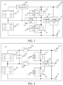
FIG. 1 is a schematic structural diagram I of a battery circuit according to an embodiment of the present disclosure; -
FIG. 2 is a schematic structural diagram II of the battery circuit according to an embodiment of the present disclosure; -
FIG. 3 is a schematic structural diagram III of the battery circuit according to an embodiment of the present disclosure; and -
FIG. 4 is a schematic structural diagram IV of the battery circuit according to an embodiment of the present disclosure. - In the drawings:
- 100-Battery circuit; 101-Power supply terminal; 102-First battery pack; 103-Second battery pack;
- 104-Voltage transformation unit; 1041-Second inductor; 105-First switch;
- 106-Second switch; 107-Grounding terminal; 108-Control unit;
- 109-Filtering unit; 1091-First inductor; 1092-First capacitor;
- 110-First freewheeling unit; 1101-First diode;
- 111-Second freewheeling unit; 1111-Second diode;
- 112-Voltage stabilization unit; 1121-Second capacitor.
- Various exemplary embodiments of the present disclosure are described in detail with reference to drawings. It should be noted that, unless otherwise specified, relative arrangement, numerical expressions, and numerical values of components and steps described in the embodiments do not limit the scope of the present disclosure.
- The following descriptions of at least one exemplary embodiment are merely illustrative, and in no way constitute any limitation on the present disclosure and the application or use thereof.
- Technologies, methods, and devices known to a person of ordinary skill in the related art may not be discussed in detail, but where appropriate, the techniques, the methods, and the devices should be considered as a part of the specification.
- In examples shown and discussed herein, any specific value should be construed as merely exemplary and not as a limitation. Therefore, other examples of the exemplary embodiments may have different values.
- It should be noted that, similar reference numerals and letters represent similar items in the following drawings. Therefore, once an item is defined in a drawing, the item does not need to be further discussed in subsequent drawings.
- An embodiment of the present disclosure provides a
battery circuit 100. As shown inFIG. 1 , thebattery circuit 100 includes apower supply terminal 101, afirst battery pack 102, asecond battery pack 103 of a different type from thefirst battery pack 102, avoltage transformation unit 104, afirst switch 105, asecond switch 106, and agrounding terminal 107. - A positive electrode of the
first battery pack 102 is connected with thepower supply terminal 101. A negative electrode of thefirst battery pack 102 is connected with a positive electrode of thesecond battery pack 103. - A negative electrode of the
second battery pack 103 is connected with thegrounding terminal 107. - A first terminal of the
first switch 105 is connected with thepower supply terminal 101. A second terminal of thefirst switch 105 is connected with a first terminal of thesecond switch 106. - A second terminal of the
second switch 106 is connected with thegrounding terminal 107. - The
voltage transformation unit 104 is connected between the negative electrode of thefirst battery pack 102 and the second terminal of thefirst switch 105. - A deviation between a rated voltage of the
first battery pack 102 and a rated voltage of thesecond battery pack 103 is less than a first preset range; and/or
a deviation between a ratio of a capacity of thefirst battery pack 102 to a capacity of thesecond battery pack 103 and a ratio of a maximum discharge rate of thesecond battery pack 103 to a maximum discharge rate of thefirst battery pack 102 is less than a second preset threshold. - In this embodiment of the present disclosure, the battery circuit is provided, which includes the power supply terminal, the first battery pack, the second battery pack of a different type from the first battery pack, the voltage transformation unit, the first switch, the second switch, and the grounding terminal. The positive electrode of the first battery pack is connected with the power supply terminal. The negative electrode of the first battery pack is connected with the positive electrode of the second battery pack. The negative electrode of the second battery pack is connected with the grounding terminal. The first terminal of the first switch is connected with the power supply terminal. The second terminal of the first switch is connected with the first terminal of the second switch. The second terminal of the second switch is connected with the grounding terminal. The voltage transformation unit is connected between the negative electrode of the first battery pack and the second terminal of the first switch. The deviation between the rated voltage of the first battery pack and the rated voltage of the second battery pack is less than the first preset range. The deviation between the ratio of the capacity of the first battery pack to the capacity of the second battery pack and the ratio of the maximum discharge rate of the second battery pack to the maximum discharge rate of the first battery pack is less than the second preset range. According to the battery circuit provided in this embodiment of the present disclosure, a hardware circuit foundation is provided for controlling a dual battery pack including the first battery pack and the second battery pack.
- In this embodiment of the present disclosure, in a case that the
battery circuit 100 is in a discharging state, thepower supply terminal 101 in thebattery circuit 100 is configured to connect to a power input terminal of a load, and thegrounding terminal 107 in thebattery circuit 100 is configured to connect to a grounding terminal of the load. Exemplarily, the load may be a motor of an electric vehicle or a hybrid vehicle. - Alternatively, in a case that the
battery circuit 100 is in a charging state, thepower supply terminal 101 in thebattery circuit 100 is configured to connect to a power output terminal of a charging device, and thegrounding terminal 107 in thebattery circuit 100 is configured to connect to a grounding terminal of the charging device. Exemplarily, the charging device may be a charging pile or a braking system of an electric vehicle or a hybrid vehicle. - In an embodiment of the present disclosure, as shown in
FIG. 4 , thevoltage transformation unit 104 may be asecond inductor 1041. Certainly, thevoltage transformation unit 104 may be implemented in another manner. - In an embodiment of the present disclosure, an inductance value of the
second inductor 1041 may be set to a range of 2 µH to 1500 µH. - In this embodiment of the present disclosure, the
voltage transformation unit 104 has a low cost and a simple structure in a case that thevoltage transformation unit 104 is thesecond inductor 1041. - In an embodiment of the present disclosure, the
first switch 105 and thesecond switch 106 may be a switch IC, a metal oxide semiconductor field effect transistor (MOSFET), an insulated gate bipolar transistor (IGBT), a silicon carbide (SiC) switch, or the like. - It may be understood that the
first switch 105 further includes a control terminal configured to control thefirst switch 105 to be closed and opened. Similarly, thesecond switch 106 further includes a control terminal configured to control thesecond switch 106 to be closed and opened. - In this embodiment of the present disclosure, the
first battery pack 102 and thesecond battery pack 103 are of different types. Specifically, thefirst battery pack 102 is a power-type battery pack, and thesecond battery pack 103 is an energy-type battery pack. Alternatively, thefirst battery pack 102 is an energy-type battery pack, and thesecond battery pack 103 is a power-type battery pack. - In this embodiment of the present disclosure, the power-type battery pack is a battery pack with a high power density. The power density is a maximum energy transfer power during charging or discharging of a battery with a unit weight or volume. In addition, in this embodiment of the present disclosure, a voltage value of the power-type battery pack may be set to a range of 100 V to 1000 V.
- The energy-type battery pack is a battery pack with a high energy density. The energy density is energy stored in a battery with a unit weight or volume. In addition, in this embodiment of the present disclosure, a voltage value of the energy-type battery pack may be set to a range of 100 V to 1000 V.
- In this embodiment of the present disclosure, specific types of the
first battery pack 102 and thesecond battery pack 103 are not limited, which can improve compatibility of thebattery circuit 100 provided in the embodiments of the present disclosure. - In this embodiment of the present disclosure, a deviation between a rated voltage U1 of the
first battery pack 102 and a rated voltage U2 of thesecond battery pack 103 is less than a first preset range. - In this embodiment of the present disclosure, the first preset range is an allowable range of the deviation between the rated voltage U1 of the
first battery pack 102 and the rated voltage U3 of thesecond battery pack 103. In a case that the deviation between the rated voltage U1 of thefirst battery pack 102 and the rated voltage U2 of thesecond battery pack 103 is less than the first preset range, it indicates that the rated voltage U1 of thefirst battery pack 102 is substantially the same as the rated voltage U2 of thesecond battery pack 103. - In an embodiment of the present disclosure, the first preset range may exemplarily be 0.2*U1 or 0.2*U2. In a case that the first preset range is 0.2*U1, 1.2*U1≥U2≥0.8*U1. In a case that the first preset range is 0.2*U2, 1.2*U2≥U1≥0.8*U2.
- It should be noted that, a specific value of the first preset range is not limited in this embodiment of the present disclosure.
- In this embodiment of the present disclosure, in a case that the deviation between the rated voltage U1 of the
first battery pack 102 and the rated voltage U2 of thesecond battery pack 103 is less than the first preset range, efficient energy transfer can be achieved between thefirst battery pack 102 and thesecond battery pack 103. For example, efficient mutual charging can be achieved between thefirst battery pack 102 and thesecond battery pack 103. - It should be noted that, generally, a sum of the rated voltage U1 of the
first battery pack 102 and the rated voltage U1 of thesecond battery pack 103 is equal to a total voltage Uout required for the load, that is, U1+U2=Uout. - In an embodiment of the present disclosure, the rated voltage U1 of the
first battery pack 102 is the same as the rated voltage U2 of thesecond battery pack 103. In this way, most efficient energy transfer can be achieved between thefirst battery pack 102 and thesecond battery pack 103. - Based on the above, in an example, Uout=550V. In this case, U1=U2=275V may be set.
- In this embodiment of the present disclosure, a deviation between a ratio of a capacity Q1 of the
first battery pack 102 to a capacity Q2 of thesecond battery pack 103 and a ratio of a maximum discharge rate X2 of thesecond battery pack 103 to a maximum discharge rate X1 of thefirst battery pack 102 is less than a second preset range. - The maximum discharge rate represents a ratio of a maximum discharging current of the battery pack to a battery capacity. For example, if a maximum discharging current of a battery pack with a battery capacity of 10 Ah is 50 A, a maximum discharge rate thereof is 50 A/10 Ah=5 C.
- In this embodiment of the present disclosure, the second preset range is an allowable range of the deviation between the ratio of the capacity Q1 of the
first battery pack 102 to the capacity Q2 of thesecond battery pack 103 and the ratio of the maximum discharge rate X2 of thesecond battery pack 103 to the maximum discharge rate X1 of thefirst battery pack 102. In a case that the deviation between the ratio of the capacity Q1 of thefirst battery pack 102 to the capacity Q2 of thesecond battery pack 103 and the ratio of the maximum discharge rate X2 of thesecond battery pack 103 to the maximum discharge rate X1 of thefirst battery pack 102 is less than the second preset range, it indicates that the ratio of the capacity Q1 of thefirst battery pack 102 to the capacity Q2 of thesecond battery pack 103 is substantially the same as the ratio of the maximum discharge rate X2 of thesecond battery pack 103 to the maximum discharge rate X1 of thefirst battery pack 102. - In an embodiment of the present disclosure, the second preset range may exemplarily be ±0.5.
- It should be noted that, a specific value of the second preset range is not limited in this embodiment of the present disclosure.
- In this embodiment of the present disclosure, in a case that the deviation between the ratio of the capacity of the
first battery pack 102 to the capacity of thesecond battery pack 103 and the ratio of the maximum discharge rate of thesecond battery pack 103 to the maximum discharge rate of thefirst battery pack 101 is less than the second preset range, maximum discharging currents of the two battery packs can be substantially the same. Based on the above, for example, the two battery packs can be connected in series for stable discharging. - It should be noted that, generally, a sum of the capacity Q1 of the
first battery pack 102 and the capacity Q2 of thesecond battery pack 103 is equal to a total capacity Qnom required for the load, that is, Q1+Q2=Qnom. - In an embodiment of the present disclosure, the ratio of the capacity Q1 of the
first battery pack 102 to the capacity Q2 of thesecond battery pack 103 is the same as the ratio of the maximum discharge rate X2 of thesecond battery pack 103 to the maximum discharge rate X1 of thefirst battery pack 102. In this way, the maximum discharging currents of the two battery packs can be exactly the same. - Based on the above, in an example, Qnom=120 Ah. In this case, Q1=100 Ah, Q2=20 Ah, X1=1 C, and X2=5 C may be set.
- The
battery circuit 100 shown inFIG. 1 provided in the embodiments of the present disclosure provides a hardware foundation for controlling a dual battery pack including a power-type battery pack and an energy-type battery pack. Specifically, according to the battery circuit shown inFIG. 1 , the dual battery pack including the power-type battery pack and the energy-type battery pack may be controlled as follows. - To achieve the control of the
first switch 105 and thesecond switch 106, as shown inFIG. 2 , thebattery circuit 100 further includes acontrol unit 108. - A first terminal of the
control unit 108 is connected with a control terminal of thefirst switch 105. A second terminal of thecontrol unit 108 is connected with a control terminal of thesecond switch 106. - In an embodiment of the present disclosure, the
control unit 108 may exemplarily be a central processing unit (CPU), a microcontroller unit (MCU), or the like. - The
control unit 108 is configured to control thefirst switch 105 and thesecond switch 106 to be opened or closed according to a first preset control rule under a first preset condition, to cause an output power of thesecond battery pack 103 to increase. - In this embodiment, the first preset condition may be that the
battery circuit 100 is in a discharging state. The first preset control rule may be performing a first on/off operation, which includes: controlling thefirst switch 105 to be opened and thesecond switch 106 to be closed within a first preset time period and controlling thefirst switch 105 to be closed and thesecond switch 106 to be opened within a second preset time period. The first on/off operation is repeated until thefirst battery pack 102 is open circuited. - In this embodiment, the second preset time period is a time period adjacent to the first preset time period and after the first preset time period. Durations corresponding to the first preset time period and the second preset time period may be set according to experience or otherwise.
- In this embodiment, in a case that the
battery circuit 100 is in the discharging state, thefirst switch 105 is controlled to be opened and thesecond switch 106 is controlled to be closed within the first preset time period. In this case, thesecond battery pack 103 charges thevoltage transformation unit 104. Thefirst switch 105 is controlled to be closed and thesecond switch 106 is controlled to be opened within the second preset time period. In this case, thevoltage transformation unit 104 releases the stored power. In other words, a voltage at the output terminal of the voltage transformation unit 104 (a terminal connected to the first switch 105) rises. The process is repeated. When the voltage at the output terminal of thevoltage transformation unit 104 rises to a same voltage as a bus, thefirst battery pack 102 is open circuited. In this way, only thesecond battery pack 103 is discharged, and the power outputted by thesecond battery pack 103 is greater than the power outputted by thesecond battery pack 103. In other words, the output power of thesecond battery pack 103 is increased. - The
control unit 108 is further configured to control thefirst switch 105 and thesecond switch 106 to be opened or closed according to a second preset control rule under a second preset condition, so that an input power of thefirst battery pack 102 is different from an input power of thesecond battery pack 103. - In this embodiment, the second preset condition may be that the
battery circuit 100 is in a charging state. The second preset control rule may be performing a second on/off operation, which includes controlling thefirst switch 105 to be closed and thesecond switch 106 to be opened within a third preset time period and controlling thefirst switch 105 to be opened and thesecond switch 106 to be closed within a fourth preset time period. The second on/off operation is repeated. - In this embodiment, the fourth preset time period is a time period adjacent to the third preset time period and after the third preset time period. Durations corresponding to the third preset time period and the fourth preset time period may be set according to experience or otherwise.
- In this embodiment, in a case that the
battery circuit 100 is in the charging state, thefirst switch 105 is controlled to be closed and thesecond switch 106 is controlled to be opened within the third preset time period. In this case, thefirst battery pack 102 and/or a charging device charges thevoltage transformation unit 104. Thefirst switch 105 is controlled to be opened and thesecond switch 106 is controlled to be closed within the fourth preset time period. In this case, thevoltage transformation unit 104 releases the stored power to charge thesecond battery pack 103 together with the charging device. In other words, thevoltage transformation unit 104 implements a boosting function. Since thefirst battery pack 102 is charged only by the charging device, while thesecond battery pack 103 is jointly charged by thevoltage transformation unit 104 and the same charging device, by repeating the process, an input power of thesecond battery pack 103 can be greater than the input power of thefirst battery pack 102. In other words, the input power of thesecond battery pack 103 is different from the input power of thefirst battery pack 102. - It may be understood that, in a case that the second preset control rule is a control rule opposite to repeating the second on/off operation, the
first switch 105 is controlled to be opened and thesecond switch 106 is controlled to be closed within the third preset time period, and thefirst switch 105 is controlled to be closed and thesecond switch 106 is controlled to be opened within the fourth preset time period. The operation is repeated. In this way, the input power of thefirst battery pack 102 can be greater than the input power of thesecond battery pack 103. In other words, the input power of thesecond battery pack 103 is different from the input power of thefirst battery pack 102. - The
control unit 108 is further configured to control thefirst switch 105 and thesecond switch 106 to be opened or closed according to a third preset control rule under a third preset condition, to cause thefirst battery pack 102 to charge thesecond battery pack 103 or cause thesecond battery pack 103 to charge thefirst battery pack 102. - In this embodiment, the third preset condition may be that a charging current of the
second battery pack 103 is less than a maximum charging current of thesecond battery pack 103. Correspondingly, the third preset control rule is performing a third on/off operation, which includes controlling thefirst switch 105 to be closed and thesecond switch 106 to be opened within a fifth preset time period and controlling thefirst switch 105 to be opened and thesecond switch 106 to be closed within a sixth preset time period. The third on/off operation is repeated. - In this embodiment, the sixth preset time period is a time period adjacent to the fifth preset time period and after the fifth preset time period. Durations corresponding to the fifth preset time period and the sixth preset time period may be set according to experience or otherwise.
- In this embodiment, in a case that the charging current of the
second battery pack 103 is less than the maximum charging current of thesecond battery pack 103, thefirst switch 105 is controlled be to be closed and thesecond switch 106 is controlled to be opened within the fifth preset time period. In this case, thefirst battery pack 102 charges thevoltage transformation unit 104. Thefirst switch 105 is controlled to be opened and thesecond switch 106 is controlled to be closed within the sixth preset time period. In this case, thevoltage transformation unit 104 releases the stored power to thesecond battery pack 103. In other words, thevoltage transformation unit 104 implements a boosting function. The process is repeated, so that thefirst battery pack 102 can charge thesecond battery pack 103. - It should be understood that, in a case that the third preset condition is that a charging current of the
first battery pack 102 is less than a maximum charging current of thefirst battery pack 102, correspondingly, the third preset control rule is a control rule opposite to repeating the third on/off operation. To be specific, thefirst switch 105 is controlled to be opened and thesecond switch 106 is controlled to be closed within the fifth preset time period, and thefirst switch 105 is controlled to be closed and thesecond switch 106 is controlled to be opened within the sixth preset time period. The operation is repeated. In this way, thesecond battery pack 103 can charge thefirst battery pack 102. - The
control unit 108 is further configured to control thefirst switch 105 and thesecond switch 106 to be opened under a fourth preset condition, to connect thefirst battery pack 102 and thesecond battery pack 103 in series for discharging or charging. - In this embodiment, the fourth preset condition is that the
battery circuit 100 is in a discharging state or a charging state. Thefirst switch 105 and thesecond switch 106 are controlled to be opened under the fourth preset condition. In this way, thefirst battery pack 102 and thesecond battery pack 103 are jointly discharged or charged. - Based on the above, the embodiments of the present disclosure provide multiple types of control according to the battery circuit shown in
FIG. 1 . - In this embodiment of the present disclosure, the battery circuit is provided, which includes the power supply terminal, the first battery pack, the second battery pack of a different type from the first battery pack, the voltage transformation unit, the first switch, the second switch, and the grounding terminal. The positive electrode of the first battery pack is connected with the power supply terminal. The negative electrode of the first battery pack is connected with the positive electrode of the second battery pack. The negative electrode of the second battery pack is connected with the grounding terminal. The first terminal of the first switch is connected with the power supply terminal. The second terminal of the first switch is connected with the first terminal of the second switch. The second terminal of the second switch is connected with the grounding terminal. The voltage transformation unit is connected between the negative electrode of the first battery pack and the second terminal of the first switch. The deviation between the rated voltage of the first battery pack and the rated voltage of the second battery pack is less than the first preset range. The deviation between the ratio of the capacity of the first battery pack to the capacity of the second battery pack and the ratio of the maximum discharge rate of the second battery pack to the maximum discharge rate of the first battery pack is less than the second preset range. According to the battery circuit provided in this embodiment of the present disclosure, a hardware circuit foundation is provided for controlling a dual battery pack including the first battery pack and the second battery pack.
- In an embodiment of the present disclosure, in a case that the
first battery pack 102 is a power-type battery pack and thesecond battery pack 103 is an energy-type battery pack, as shown inFIG. 3 , thebattery circuit 100 provided in this embodiment of the present disclosure further includes afiltering unit 109. - A first terminal of the
filtering unit 109 is connected with the positive electrode of thefirst battery pack 102. A second terminal of thefiltering unit 109 is connected with thepower supply terminal 101. A third terminal of thefiltering unit 109 is connected with the negative electrode of thefirst battery pack 102. - In this embodiment of the present disclosure, since the power-type battery pack is usually used only in a case that a peak power is generated during the traveling of the electric vehicle or the hybrid vehicle (such as the peak discharging power generated during traction and the peak charging power generated during the braking), in other cases, an output current of the power-type battery pack is expected to be 0. In these cases, arranging the
filtering unit 109 can suppress a current ripple of thefirst battery pack 102, to prevent the output current of the power-type battery pack (the first battery pack 102) from fluctuating around 0. In this way, high-frequency rapid charging/discharging of thefirst battery pack 102 can be avoided, thereby reducing a life decrease of thefirst battery pack 102. - In an embodiment of the present disclosure, as shown in
FIG. 4 , thefiltering unit 109 includes afirst inductor 1091 and afirst capacitor 1092. - A first terminal of the
first inductor 1091 is connected with the positive electrode of thefirst battery pack 102. A second terminal of thefirst inductor 1091 is connected with the power supply terminal. - A first terminal of the
first capacitor 1092 is connected with the first terminal of thefirst inductor 1091. A second terminal of thefirst capacitor 1092 is connected with the negative electrode of thefirst battery pack 102. - Certainly, a
filtering unit 109 of another structure may also be used, which is not described in detail in this embodiment of the present disclosure. - In this embodiment of the present disclosure, the
first inductor 1091 is a filter inductor, and thefirst inductor 1091 may be configured with a value in a range of 2 µH to 1500 µH. Thefirst capacitor 1092 is a filter capacitor, thefirst capacitor 1092 may be configured with a value a range of 2 µF to 1500 µF. - It should be noted that, in a case that the
first battery pack 102 has a filtering function, thefirst inductor 1091 and thefirst capacitor 1092 may be configured with relatively small values. For example, thefirst inductor 1091 may be configured with a value of 2 µH, and thefirst capacitor 1092 may be configured with a value of 2 µF. - Correspondingly, in a case that the
first battery pack 102 does not have the filtering function, thefirst inductor 1091 and thefirst capacitor 1092 may be configured with relatively large values. For example, thefirst inductor 1091 may be configured with a value of 1500 µH, and thefirst capacitor 1092 may be configured with a value of 1500 µF. - In this embodiment of the present disclosure, the
filtering unit 109 with a simple structure is provided, which can reduce hardware costs, design difficulty, and a footprint of thebattery circuit 100. - In an embodiment of the present disclosure, as shown in
FIG. 3 , thebattery circuit 100 provided in this embodiment of the present disclosure further includes a firstfreewheeling unit 110 and a secondfreewheeling unit 111. - An input terminal of the first
freewheeling unit 110 is connected with the second terminal of thefirst switch 105. An output terminal of the firstfreewheeling unit 110 is connected with the first terminal of thefirst switch 105. - An input terminal of the second
freewheeling unit 111 is connected with the second terminal of thesecond switch 106. An output terminal of the secondfreewheeling unit 111 is connected with the first terminal of thesecond switch 106. - In this embodiment of the present disclosure, at an initial moment of closing the
second switch 106 and opening thefirst switch 105, thefirst switch 105 usually cannot be controlled to be immediately opened as a result of freewheeling time and action time of thefirst switch 105. As a result, a short circuit quickly occurs between thefirst switch 105 and thesecond switch 106, which causes thefirst battery pack 102 and thesecond battery pack 103 to be burnt. - In this embodiment of the present disclosure, the second
freewheeling unit 111 is connected in parallel with the two terminals of thesecond switch 106, and the secondfreewheeling unit 111 performs freewheeling. In this way, closing time of thesecond switch 106 can be delayed during control of thefirst switch 105 to be opened, thereby preventing thefirst battery pack 102 and thesecond battery pack 103 from being burnt by a short circuit. - Similarly, in this embodiment of the present disclosure, the first
freewheeling unit 110 is connected in parallel with the two terminals of thefirst switch 105, and the firstfreewheeling unit 110 performs freewheeling. In this way, closing time of thefirst switch 105 can be delayed during control of thesecond switch 106 to be opened, thereby preventing thefirst battery pack 102 and thesecond battery pack 103 from being burnt by a short circuit. - In an embodiment of the present disclosure, as shown in
FIG. 4 , the firstfreewheeling unit 109 is afirst diode 1101, and the secondfreewheeling unit 111 is asecond diode 1111. - An anode of the
first diode 1101 is connected with the second terminal of thefirst switch 105. A cathode of thefirst diode 1101 is connected with the first terminal of thefirst switch 105. - An anode of the
second diode 1111 is connected with the second terminal of thesecond switch 106. A cathode of thesecond diode 1111 is connected with the first terminal of thesecond switch 106. - In this embodiment of the present disclosure, the first
freewheeling unit 110 and the secondfreewheeling unit 111 with a simple structure are provided, which can reduce hardware costs, design difficulty, and a footprint of thebattery circuit 100. - In an embodiment of the present disclosure, as shown in
FIG. 3 , thebattery circuit 100 provided in this embodiment of the present disclosure further includes avoltage stabilization unit 112. - The
voltage stabilization unit 112 is connected between thepower supply terminal 101 and thegrounding terminal 107. - In this embodiment of the present disclosure, the
voltage stabilization unit 111 is configured to filter out a voltage fluctuation on a bus, that is, a line on which thepower supply terminal 101 of thebattery circuit 100 is located, which can stabilize a voltage supplied to the load, and is further configured to reduce negative impact of a voltage fluctuation jointly generated by thefirst battery pack 102 and thevoltage transformation unit 104 on thesecond battery pack 103. - In an embodiment of the present disclosure, as shown in
FIG. 4 , thevoltage stabilization unit 112 may exemplarily be asecond capacitor 1121. Certainly, thevoltage stabilization unit 112 may be implemented in another manner. - In an embodiment of the present disclosure, the
second capacitor 1121 is a support capacitor, and thesecond capacitor 1121 may be configured with a value in a range of 2 µF to 1500 µF. - In this embodiment of the present disclosure, the
voltage stabilization unit 112 with a simple structure is provided, which can reduce hardware costs, design difficulty, and a footprint of thebattery circuit 100. - An embodiment of the present disclosure further provides a vehicle. The vehicle includes the
battery circuit 100 in any of the foregoing embodiments. - In this embodiment of the present disclosure, the vehicle is an electric vehicle or a hybrid vehicle.
- The embodiments of the present disclosure have been described above. The above description is exemplary and non-exhaustive, and the present disclosure is not limited to the disclosed embodiments. Many modifications and changes made without departing from the scope and the spirit of the various embodiments are apparent to a person of ordinary skill in the art. The selection of the terms used herein is intended to provide best explanation of the principles, practical applications of the various embodiments, or technical improvements of the technologies in the market, or to enable others of ordinary skill in the art to understand the embodiments disclosed herein. The scope of the present disclosure is defined by the appended claims.
Claims (12)
- A battery circuit (100), comprising a power supply terminal (101), a first battery pack (102), a second battery pack (103) of a different type from the first battery pack (102), a voltage transformation unit (104), a first switch (105), a second switch (106), and a grounding terminal (107), whereina positive electrode of the first battery pack (102) is connected with the power supply terminal (101); a negative electrode of the first battery pack (102) is connected with a positive electrode of the second battery pack (103);a negative electrode of the second battery pack (103) is connected with the grounding terminal (107);a first terminal of the first switch (105) is connected with the power supply terminal (101); a second terminal of the first switch (105) is connected with a first terminal of the second switch (106);a second terminal of the second switch (106) is connected with the grounding terminal (107); andthe voltage transformation unit (104) is connected between the negative electrode of the first battery pack (102) and the second terminal of the first switch (105);wherein a deviation between a rated voltage of the first battery pack (102) and a rated voltage of the second battery pack (103) is less than a first preset range; and/ora deviation between a ratio of a capacity of the first battery pack (102) to a capacity of the second battery pack (103) and a ratio of a maximum discharge rate of the second battery pack (103) to a maximum discharge rate of the first battery pack (102) is less than a second preset range.
- The battery circuit (100) according to claim 1, wherein the rated voltage of the first battery pack (102) is the same as the rated voltage of the second battery pack (103); and/or
the ratio of the capacity of the first battery pack (102) to the capacity of the second battery pack (103) is the same as the ratio of the maximum discharge rate of the second battery pack (103) to the maximum discharge rate of the first battery pack (102). - The battery circuit (100) according to claim 1 or 2, further comprising:a control unit (108), a first terminal of the control unit (108) being connected with a control terminal of the first switch (105), and a second terminal of the control unit (108) being connected with a control terminal of the second switch (106), whereinthe control unit (108) is configured to: control the first switch (105) and the second switch (106) to be opened or closed according to a first preset control rule under a first preset condition, to cause an output power of the second battery pack (103) to increase; and/orcontrol the first switch (105) and the second switch (106) to be opened or closed according to a second preset control rule under a second preset condition, so that an input power of the first battery pack (102) is different from an input power of the second battery pack (103); and/orcontrol the first switch (105) and the second switch (106) to be opened or closed according to a third preset control rule under a third preset condition, to cause the first battery pack (102) to charge the second battery pack (103) or cause the second battery pack (103) to charge the first battery pack (102); and/orcontrol the first switch (105) and the second switch (106) to be opened under a fourth preset condition, to connect the first battery pack (102) and the second battery pack (103) in series for discharging or charging.
- The battery circuit (100) according to any of claims 1 to 3, wherein the first battery pack (102) is a power-type battery pack; and the second battery pack (103) is an energy-type battery pack; or
the first battery pack (102) is an energy-type battery pack; and the second battery pack (103) is a power-type battery pack. - The battery circuit (100) according to claim 4, wherein the first battery pack (102) is a power-type battery pack; the second battery pack (103) is an energy-type battery pack; and the battery circuit (100) further comprises a filtering unit (109), wherein
a first terminal of the filtering unit (109) is connected with the positive electrode of the first battery pack (102); a second terminal of the filtering unit (109) is connected with the power supply terminal (101); and a third terminal of the filtering unit (109) is connected with the negative electrode of the first battery pack (102). - The battery circuit (100) according to claim 5, wherein the filtering unit (109) comprises a first inductor (1091) and a first capacitor (1092), whereina first terminal of the first inductor (1091) is connected with the positive electrode of the first battery pack (102); a second terminal of the first inductor (1091) is connected with the power supply terminal (101);a first terminal of the first capacitor (1092) is connected with the first terminal of the first inductor (1091); and a second terminal of the first capacitor (1092) is connected with the negative electrode of the first battery pack (102).
- The battery circuit (100) according to any of claims 1 to 6, further comprising a first freewheeling unit (110) and a second freewheeling unit (111), whereinan input terminal of the first freewheeling unit (110) is connected with the second terminal of the first switch (105); an output terminal of the first freewheeling unit (110) is connected with the first terminal of the first switch (105);an input terminal of the second freewheeling unit (111) is connected with the second terminal of the second switch (106); and an output terminal of the second freewheeling unit (111) is connected with the first terminal of the second switch (106).
- The battery circuit (100) according to claim 7, wherein the first freewheeling unit (110) is a first diode (1101); and the second freewheeling unit (111) is a second diode (1111), whereinan anode of the first diode (1101) is connected with the second terminal of the first switch (105); a cathode of the first diode (1101) is connected with the first terminal of the first switch (105);an anode of the second diode (1111) is connected with the second terminal of the second switch (106); and a cathode of the second diode (1111) is connected with the first terminal of the second switch (106).
- The battery circuit (100) according to any of claims 1 to 8, further comprising a voltage stabilization unit (112), wherein
the voltage stabilization unit (112) is connected between the power supply terminal (101) and the grounding terminal (107). - The battery circuit (100) according to claim 9, wherein the voltage stabilization unit (112) is a second capacitor (1121).
- The battery circuit (100) according to any of claims 1 to 10, wherein the voltage transformation unit (104) is a second inductor (1041).
- A vehicle, comprising the battery circuit (100) according to any of claims 1 to 11.
Applications Claiming Priority (2)
| Application Number | Priority Date | Filing Date | Title |
|---|---|---|---|
| CN202210614132.8A CN117183813B (en) | 2022-05-31 | 2022-05-31 | Battery circuit and vehicle |
| PCT/CN2023/079719 WO2023231485A1 (en) | 2022-05-31 | 2023-03-06 | Battery circuit and vehicle |
Publications (2)
| Publication Number | Publication Date |
|---|---|
| EP4534342A1 true EP4534342A1 (en) | 2025-04-09 |
| EP4534342A4 EP4534342A4 (en) | 2025-10-15 |
Family
ID=89002254
Family Applications (1)
| Application Number | Title | Priority Date | Filing Date |
|---|---|---|---|
| EP23814684.9A Pending EP4534342A4 (en) | 2022-05-31 | 2023-03-06 | BATTERY CIRCUIT AND VEHICLE |
Country Status (6)
| Country | Link |
|---|---|
| US (1) | US20250033526A1 (en) |
| EP (1) | EP4534342A4 (en) |
| JP (1) | JP2025515947A (en) |
| KR (1) | KR20240155898A (en) |
| CN (1) | CN117183813B (en) |
| WO (1) | WO2023231485A1 (en) |
Family Cites Families (23)
| Publication number | Priority date | Publication date | Assignee | Title |
|---|---|---|---|---|
| US5479083A (en) * | 1993-06-21 | 1995-12-26 | Ast Research, Inc. | Non-dissipative battery charger equalizer |
| JPH07123703A (en) * | 1993-10-20 | 1995-05-12 | N F Kairo Sekkei Block:Kk | Conversion circuit |
| JP3625789B2 (en) * | 2001-08-10 | 2005-03-02 | 本田技研工業株式会社 | Vehicle power supply |
| JP2009142069A (en) * | 2007-12-06 | 2009-06-25 | Gs Yuasa Corporation:Kk | Temperature regulator of battery pack and temperature regulation method of battery pack |
| JP2010057291A (en) * | 2008-08-28 | 2010-03-11 | Sanyo Electric Co Ltd | Power supply for vehicle |
| US9209644B2 (en) * | 2010-07-30 | 2015-12-08 | Byd Company Limited | Circuits and methods for heating batteries in series using resonance components in series |
| JP5887077B2 (en) * | 2011-07-21 | 2016-03-16 | 本田技研工業株式会社 | Power supply system and fuel cell vehicle |
| US9118201B2 (en) * | 2012-05-08 | 2015-08-25 | General Electric Company | Systems and methods for energy transfer control |
| JP6065821B2 (en) * | 2013-12-06 | 2017-01-25 | 株式会社豊田自動織機 | Cell charge / discharge power / current limiting device, battery charge / discharge power / current limiting device, and battery pack |
| JP2015171310A (en) * | 2014-03-11 | 2015-09-28 | 株式会社豊田自動織機 | Voltage equalization apparatus and voltage equalization method |
| FR3029709B1 (en) * | 2014-12-05 | 2018-01-19 | Valeo Equipements Electriques Moteur | POWER SUPPLY DEVICE AND IMPROVED CONTINUOUS VOLTAGE CONVERTER |
| EP4475269A3 (en) * | 2016-08-10 | 2025-03-19 | Briggs & Stratton, LLC | User-scalable power unit including removable battery packs |
| CN108808754B (en) * | 2017-05-03 | 2020-10-16 | 华为技术有限公司 | Distributed battery, battery control method and electric vehicle |
| CN109130891B (en) * | 2018-10-18 | 2020-05-19 | 西安交通大学 | Composite topological structure of multi-mode hybrid energy storage system of electric vehicle and control method |
| CN209823441U (en) * | 2018-12-21 | 2019-12-20 | 蔚来汽车有限公司 | Voltage conversion control device for power battery and electric vehicle |
| JP7370223B2 (en) * | 2019-01-24 | 2023-10-27 | 株式会社Soken | power converter |
| GB2584829B (en) * | 2019-06-04 | 2023-01-11 | Jaguar Land Rover Ltd | Vehicle traction battery circuit and control system |
| CN112848969A (en) * | 2019-11-27 | 2021-05-28 | 光阳工业股份有限公司 | Battery parallel control method for electric vehicle |
| CN111422100A (en) * | 2019-11-29 | 2020-07-17 | 蜂巢能源科技有限公司 | Heating circuits for battery packs, power systems and electric vehicles |
| JP2022002430A (en) * | 2020-06-19 | 2022-01-06 | マツダ株式会社 | Vehicular drive system |
| CN111628653B (en) * | 2020-06-30 | 2025-02-28 | 博格华纳驱动系统(苏州)有限公司 | Boost and buck control device and method for bidirectional three-level DC-DC converter |
| CN112677821B (en) * | 2020-12-30 | 2024-11-08 | 珠海冠宇动力电池有限公司 | Battery systems and electric vehicles |
| CN113696785A (en) * | 2021-09-06 | 2021-11-26 | 鲨港科技(上海)有限公司 | Control circuit of series power supply pack, charging and discharging method and vehicle |
-
2022
- 2022-05-31 CN CN202210614132.8A patent/CN117183813B/en active Active
-
2023
- 2023-03-06 EP EP23814684.9A patent/EP4534342A4/en active Pending
- 2023-03-06 WO PCT/CN2023/079719 patent/WO2023231485A1/en not_active Ceased
- 2023-03-06 JP JP2024568427A patent/JP2025515947A/en active Pending
- 2023-03-06 KR KR1020247031428A patent/KR20240155898A/en active Pending
-
2024
- 2024-10-16 US US18/917,397 patent/US20250033526A1/en active Pending
Also Published As
| Publication number | Publication date |
|---|---|
| CN117183813A (en) | 2023-12-08 |
| KR20240155898A (en) | 2024-10-29 |
| US20250033526A1 (en) | 2025-01-30 |
| CN117183813B (en) | 2025-07-11 |
| WO2023231485A1 (en) | 2023-12-07 |
| JP2025515947A (en) | 2025-05-20 |
| EP4534342A4 (en) | 2025-10-15 |
Similar Documents
| Publication | Publication Date | Title |
|---|---|---|
| EP4534341A1 (en) | Battery circuit and vehicle | |
| EP4534338A1 (en) | Battery circuit and vehicle | |
| US9000740B2 (en) | Two-directional current double-boost quadratic DC/DC converter | |
| EP2378622B1 (en) | Trickle charger for high-energy storage systems | |
| WO2010140217A1 (en) | Power supply system | |
| CN117977763A (en) | A battery energy storage parallel balanced converter topology and control method thereof | |
| EP4534342A1 (en) | Battery circuit and vehicle | |
| CN112803388B (en) | Discharging system of energy storage device and ground discharging system of new energy traffic vehicle | |
| EP4535601A1 (en) | Battery circuit and vehicle | |
| CN107910931A (en) | A kind of control method of single group and multigroup energy storage converting means | |
| CN220562583U (en) | Multi-group battery parallel control system of electric vehicle | |
| CN219339219U (en) | Charging and discharging systems and vehicles | |
| EP4470826A1 (en) | Battery circuit, control method for battery circuit, and vehicle | |
| CN117183811B (en) | Battery circuit and vehicle | |
| EP4270754A1 (en) | Conversion circuit, voltage conversion apparatus and electric vehicle | |
| CN216819431U (en) | Pulse charge-discharge system port circuit and pulse charge-discharge system | |
| WO2025161965A1 (en) | Circuit system, electric device, and vehicle operating mode control method | |
| JP2002218653A (en) | Power converter using electric double layer capacitor | |
| CN121841111A (en) | A power smoothing power converter based on buck-boost topology | |
| WO2024046180A1 (en) | Hybrid battery charging circuit, method, device, and storage medium | |
| CN120728808A (en) | A step-up/step-down circuit for sodium ion batteries |
Legal Events
| Date | Code | Title | Description |
|---|---|---|---|
| STAA | Information on the status of an ep patent application or granted ep patent |
Free format text: STATUS: THE INTERNATIONAL PUBLICATION HAS BEEN MADE |
|
| PUAI | Public reference made under article 153(3) epc to a published international application that has entered the european phase |
Free format text: ORIGINAL CODE: 0009012 |
|
| STAA | Information on the status of an ep patent application or granted ep patent |
Free format text: STATUS: REQUEST FOR EXAMINATION WAS MADE |
|
| 17P | Request for examination filed |
Effective date: 20240925 |
|
| AK | Designated contracting states |
Kind code of ref document: A1 Designated state(s): AL AT BE BG CH CY CZ DE DK EE ES FI FR GB GR HR HU IE IS IT LI LT LU LV MC ME MK MT NL NO PL PT RO RS SE SI SK SM TR |
|
| DAV | Request for validation of the european patent (deleted) | ||
| DAX | Request for extension of the european patent (deleted) | ||
| A4 | Supplementary search report drawn up and despatched |
Effective date: 20250915 |
|
| RIC1 | Information provided on ipc code assigned before grant |
Ipc: B60L 58/18 20190101AFI20250909BHEP Ipc: B60L 58/22 20190101ALI20250909BHEP |