EP4534293A1 - Drum for holding sheets of print media with automatic tensioner - Google Patents
Drum for holding sheets of print media with automatic tensioner Download PDFInfo
- Publication number
- EP4534293A1 EP4534293A1 EP23202004.0A EP23202004A EP4534293A1 EP 4534293 A1 EP4534293 A1 EP 4534293A1 EP 23202004 A EP23202004 A EP 23202004A EP 4534293 A1 EP4534293 A1 EP 4534293A1
- Authority
- EP
- European Patent Office
- Prior art keywords
- strip
- sheet holding
- cable
- drum
- tensioner
- Prior art date
- Legal status (The legal status is an assumption and is not a legal conclusion. Google has not performed a legal analysis and makes no representation as to the accuracy of the status listed.)
- Pending
Links
Images

Classifications
-
- B—PERFORMING OPERATIONS; TRANSPORTING
- B41—PRINTING; LINING MACHINES; TYPEWRITERS; STAMPS
- B41F—PRINTING MACHINES OR PRESSES
- B41F25/00—Devices for pressing sheets or webs against cylinders, e.g. for smoothing purposes
-
- B—PERFORMING OPERATIONS; TRANSPORTING
- B41—PRINTING; LINING MACHINES; TYPEWRITERS; STAMPS
- B41F—PRINTING MACHINES OR PRESSES
- B41F21/00—Devices for conveying sheets through printing apparatus or machines
- B41F21/10—Combinations of transfer drums and grippers
- B41F21/102—Combinations of transfer drums and grippers with pneumatic means
-
- B—PERFORMING OPERATIONS; TRANSPORTING
- B41—PRINTING; LINING MACHINES; TYPEWRITERS; STAMPS
- B41F—PRINTING MACHINES OR PRESSES
- B41F30/00—Devices for attaching coverings or make-ready devices; Guiding devices for coverings
- B41F30/02—Devices for attaching coverings or make-ready devices; Guiding devices for coverings attaching to impression cylinders
-
- B—PERFORMING OPERATIONS; TRANSPORTING
- B41—PRINTING; LINING MACHINES; TYPEWRITERS; STAMPS
- B41J—TYPEWRITERS; SELECTIVE PRINTING MECHANISMS, i.e. MECHANISMS PRINTING OTHERWISE THAN FROM A FORME; CORRECTION OF TYPOGRAPHICAL ERRORS
- B41J13/00—Devices or arrangements of selective printing mechanisms, e.g. ink-jet printers or thermal printers, specially adapted for supporting or handling copy material in short lengths, e.g. sheets
- B41J13/10—Sheet holders, retainers, movable guides, or stationary guides
- B41J13/22—Clamps or grippers
- B41J13/223—Clamps or grippers on rotatable drums
- B41J13/226—Clamps or grippers on rotatable drums using suction
-
- B—PERFORMING OPERATIONS; TRANSPORTING
- B65—CONVEYING; PACKING; STORING; HANDLING THIN OR FILAMENTARY MATERIAL
- B65H—HANDLING THIN OR FILAMENTARY MATERIAL, e.g. SHEETS, WEBS, CABLES
- B65H29/00—Delivering or advancing articles from machines; Advancing articles to or into piles
- B65H29/24—Delivering or advancing articles from machines; Advancing articles to or into piles by air blast or suction apparatus
- B65H29/241—Suction devices
- B65H29/243—Suction rollers
-
- B—PERFORMING OPERATIONS; TRANSPORTING
- B65—CONVEYING; PACKING; STORING; HANDLING THIN OR FILAMENTARY MATERIAL
- B65H—HANDLING THIN OR FILAMENTARY MATERIAL, e.g. SHEETS, WEBS, CABLES
- B65H5/00—Feeding articles separated from piles; Feeding articles to machines
- B65H5/08—Feeding articles separated from piles; Feeding articles to machines by grippers, e.g. suction grippers
- B65H5/12—Revolving grippers, e.g. mounted on arms, frames or cylinders
-
- B—PERFORMING OPERATIONS; TRANSPORTING
- B65—CONVEYING; PACKING; STORING; HANDLING THIN OR FILAMENTARY MATERIAL
- B65H—HANDLING THIN OR FILAMENTARY MATERIAL, e.g. SHEETS, WEBS, CABLES
- B65H5/00—Feeding articles separated from piles; Feeding articles to machines
- B65H5/08—Feeding articles separated from piles; Feeding articles to machines by grippers, e.g. suction grippers
- B65H5/14—Details of grippers; Actuating-mechanisms therefor
-
- B—PERFORMING OPERATIONS; TRANSPORTING
- B65—CONVEYING; PACKING; STORING; HANDLING THIN OR FILAMENTARY MATERIAL
- B65H—HANDLING THIN OR FILAMENTARY MATERIAL, e.g. SHEETS, WEBS, CABLES
- B65H5/00—Feeding articles separated from piles; Feeding articles to machines
- B65H5/22—Feeding articles separated from piles; Feeding articles to machines by air-blast or suction device
- B65H5/222—Feeding articles separated from piles; Feeding articles to machines by air-blast or suction device by suction devices
- B65H5/226—Feeding articles separated from piles; Feeding articles to machines by air-blast or suction device by suction devices by suction rollers
-
- B—PERFORMING OPERATIONS; TRANSPORTING
- B41—PRINTING; LINING MACHINES; TYPEWRITERS; STAMPS
- B41F—PRINTING MACHINES OR PRESSES
- B41F23/00—Devices for treating the surfaces of sheets, webs, or other articles in connection with printing
- B41F23/04—Devices for treating the surfaces of sheets, webs, or other articles in connection with printing by heat drying, by cooling, by applying powders
- B41F23/044—Drying sheets, e.g. between two printing stations
- B41F23/045—Drying sheets, e.g. between two printing stations by radiation
- B41F23/0453—Drying sheets, e.g. between two printing stations by radiation by ultraviolet dryers
-
- B—PERFORMING OPERATIONS; TRANSPORTING
- B41—PRINTING; LINING MACHINES; TYPEWRITERS; STAMPS
- B41F—PRINTING MACHINES OR PRESSES
- B41F23/00—Devices for treating the surfaces of sheets, webs, or other articles in connection with printing
- B41F23/04—Devices for treating the surfaces of sheets, webs, or other articles in connection with printing by heat drying, by cooling, by applying powders
- B41F23/044—Drying sheets, e.g. between two printing stations
- B41F23/045—Drying sheets, e.g. between two printing stations by radiation
- B41F23/0456—Drying sheets, e.g. between two printing stations by radiation by infrared dryers
-
- B—PERFORMING OPERATIONS; TRANSPORTING
- B41—PRINTING; LINING MACHINES; TYPEWRITERS; STAMPS
- B41F—PRINTING MACHINES OR PRESSES
- B41F23/00—Devices for treating the surfaces of sheets, webs, or other articles in connection with printing
- B41F23/04—Devices for treating the surfaces of sheets, webs, or other articles in connection with printing by heat drying, by cooling, by applying powders
- B41F23/044—Drying sheets, e.g. between two printing stations
- B41F23/0463—Drying sheets, e.g. between two printing stations by convection
- B41F23/0469—Drying sheets, e.g. between two printing stations by convection by using gas or fuel burners
-
- B—PERFORMING OPERATIONS; TRANSPORTING
- B41—PRINTING; LINING MACHINES; TYPEWRITERS; STAMPS
- B41J—TYPEWRITERS; SELECTIVE PRINTING MECHANISMS, i.e. MECHANISMS PRINTING OTHERWISE THAN FROM A FORME; CORRECTION OF TYPOGRAPHICAL ERRORS
- B41J11/00—Devices or arrangements of selective printing mechanisms, e.g. ink-jet printers or thermal printers, for supporting or handling copy material in sheet or web form
- B41J11/0015—Devices or arrangements of selective printing mechanisms, e.g. ink-jet printers or thermal printers, for supporting or handling copy material in sheet or web form for treating before, during or after printing or for uniform coating or laminating the copy material before or after printing
- B41J11/002—Curing or drying the ink on the copy materials, e.g. by heating or irradiating
-
- B—PERFORMING OPERATIONS; TRANSPORTING
- B65—CONVEYING; PACKING; STORING; HANDLING THIN OR FILAMENTARY MATERIAL
- B65H—HANDLING THIN OR FILAMENTARY MATERIAL, e.g. SHEETS, WEBS, CABLES
- B65H2404/00—Parts for transporting or guiding the handled material
- B65H2404/40—Shafts, cylinders, drums, spindles
Definitions
- US 9546070 B2 discloses a sheet holding drum for a printer.
- the drum comprises a cylindrical body, a strip spiraling around the cylindrical body to form a sheet holding surface, to which a sheet can be releasably held by means of a negative pressure applied to suction holes in the strip, and a tensioner assembly for exerting a tensioning force on both ends of the strip to tension the strip around the cylindrical body.
- a drum may be used in a fixation unit of a printer for drying the ink printed on the sheets by heating them.
- the drum is preferably sufficiently large to hold multiple sheets and/or to provide sufficient time to heat and/or dry the sheets.
- the drum is heated locally, which results in thermal expansion and contraction in the strip.
- the strip is tensioned by means of the tensioner assembly pulling on either end. It was found however that during operation, forces due to thermal expansion and compression could exceed that of the tensioner assembly. In addition, localized heating of the rotating drum could result in a drifting of the tensioner assembly. Manual correction is then required to restore the tensioner assembly's position.
- a sheet holding drum for printer according to claim 1 and a printer according to claim 11 are provided.
- the sheet holding drum comprises:
- the sheet holding drum is characterized in that the tensioner assembly comprises at least one automatic tensioner, which automatic tensioner comprises a one directional restrictor and urging means for compensating for movement of ends of the strip.
- the first body is formed as a housing, wherein the second body is movable inside the housing, so that amount of a cable connected to an end of the strip can be taken up inside the housing by the urging means moving the second body with respect to the first body. Cable can enter the housing by being pulled in by urging means, but once taken up that portion of the cable does not substantially exit the housing due to the one-directional restrictor preventing it from moving opposite to the direction it entered the housing.
- both ends of the strip are connected to one another via the tensioner assembly.
- the strip with the tensioner assembly connecting its ends forms an endless loop.
- a single spring can be used to provide a pre-tension on both ends.
- a respective tensioner assembly may be provided between the cylindrical body and each end of the strip, wherein in one or both tensioner assembly may comprise an automatic tensioner.
- the tensioner assembly is positioned inside the cylindrical body.
- the cylindrical body has a hollow center, in which the tensioner assembly is placed.
- the tensioner assembly extends diagonally from one edge of the cylindrical body to the other.
- the strip may extend into the hollow center or be provided with e.g. levers to connect to the tensioner assembly. This results in a compact embodiment, wherein the sheet holding surface on the drum can be maximized.
- the one directional restrictor of one automatic tensioner is arranged opposite to that of the other automatic tensioner.
- the two automatic tensioners are arranged to act opposite to one another. Thermal expansion causes both ends of the strip to move towards the tensioning spring, but in opposite directions. The length increase or slack at each end is compensated by the respective automatic tensioner there. Thereby, the tensioner assembly remains effectively in place inside the cylindrical body.
- each automatic tensioner comprises a first and a second body movable with respect to one another within a predetermined range defined by a limiter, preferably substantially fixed with respect to the cylindrical body.
- the movement range defined limiter by the limiter may preferably be fixed relative to the cylindrical body.
- the second body is thus able to move within a limited range with respect to the cylindrical body. The range is selected, so that the strip remains operational on the drum, preventing damage or drifting.
- the limiter comprises guide slits in the first body that limit movement of the second body.
- Guide slits are a simple to manufacture embodiment.
- the first body may be a housing that holds the second body.
- the second body has one or more protrusions that engage the guide slits.
- the guide slits are formed in a housing which holds the second body, and wherein the housing is rigidly connected to the cylindrical body.
- the housing is mounted onto the cylindrical at a fixed, relative position.
- the housing may be pivotable or rotatable with respect to the cylindrical body, but its connection is substantially rigid. Thereby, the range is defined with respect to the cylindrical body, allowing it to be set accurately.
- the guide slits thus define end points for or a range of movement of the second body with respect to the cylindrical body.
- the one-directional restrictor comprises a plate with an opening through which the cable extends, which plate is tiltable with respect the first body between:
- the cable In the open state, the cable can move freely through the opening in the direction wherein the urging means pull or push the second body.
- the plate In the close state, the plate is tilted, so that the opening effectively becomes too narrow for the cable to pass through, resulting in the cable becoming trapped by the plate.
- the two states are defined by end points fixed with respect to the housing, so that the plate is movable within a limited range with respect to the first body.
- the end points for open state preferably position the plate substantially perpendicular to said direction, while in the closed state the plate is skewed or inclined with respect to said direction, so that the opening when viewed in said direction is smaller as compared to the open state.
- the urging means drive the plate against the end points for open state in said direction, while in case of sufficient tension on the respective end of the strip the plate is pulled into its inclined orientation against the end points which define the closed state by said tension.
- the present invention further relates to a printer comprising a sheet holding drum as described above.
- the drum is preferably provided with a drive for rotating it, as well as releasing means to release sheets from the drum.
- the printer further comprises a fixation unit for heating sheets held on the sheet holding drum, which in consequence also heats the drum. Heat is applied to the drum along a fixed angular portion, so that the rotating periphery of the drum is locally heated. Outside this angular portion, the periphery of the drum cools down, which results in a temperature gradient across the drum. The angular velocity of the drum may affect the temperature gradient.
- the strip undergoes cycles of thermal expansion and contraction while on the rotating drum. The effects of those cycles are reduced by means of the above described tensioner assembly.
- the fixation unit may comprise a heating system to transfer energy to the sheets, for example a heater gas blower or IR or UV radiator.
- Fig. 1 schematically illustrates a sheet holding drum 1 for use in a sheet printer.
- the drum 1 forms part of the transport path of the printer and is configured to releasable hold sheets against its outer surface.
- the drum 1 may be used in any suitable position along the transport path, but is particularly advantageous when applied in a fixation unit for solidifying ink on the sheets.
- Such a drum 1 is known from e.g. US 9546070 B2 , the contents of which are herein incorporated by reference.
- Fig. 2 illustrates a cross-sectional view of the drum 1.
- the cylindrical body 2 is provided with suction channels 4, which are formed as axially extending chambers at the periphery of the cylindrical body 2. At least one axial end of the suction channels 4 is connected to a suction channel or manifold (not shown) besides the cylindrical body 2 to connect the suction channels 4 to the suction source.
- the suction source can e.g. be a pump or fan.
- the suction channels 4 comprise an open side in the outward radial direction, which open side is covered by the spiraling strip 3. Thus, a negative pressure can be applied to the suction holes in the strip 3 to hold sheets against the drum 1.
- the hollow cylindrical body 2 further defines a substantially empty or free inner volume 5.
- the tensioner assembly 10 is positioned.
- the tensioner assembly 10 connects the opposite ends of the spiraling strip 3 together, so that a substantially constant tension force is applied to the strip 3.
- the tensioner assembly 10 comprises a tensioning spring 14, which on both ends is provided with automatic tensioners 20, 20'.
- Each automatic tensioner 20, 20' comprises a slack compensating mechanism, so that the tensioner assembly 10 remains substantially in position if the positions of the ends of the strip 3 change due to thermal effects.
- Each automatic tensioners 20, 20' is mounted onto the cylindrical body 2 by means of the fasteners 11, 11'.
- the fasteners 11, 11' are optional, but aid in maintaining the automatic tensioners 20, 20' in position with respect to the cylindrical body 2.
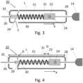
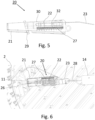
- the first automatic tensioner 20 is illustrated schematically in Fig. 3 and 4 and in detail in Fig. 5 and 6 .
- the first automatic tensioner 20 will be discussed here below.
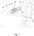
- the second automatic tensioner 20' is illustrated in Fig. 7 . It will be appreciated that the second automatic tensioner 20' is configured similar to the first automatic tensioner 20, but arranged so that it acts in the opposite direction. Preferably the two automatic tensioners 20, 20' are mirror symmetric with respect to one another.
- the automatic tensioner 20 comprises a first body 21 and a second body 22.
- the second body 22 is mounted movably in the first body 21, so that the bodies 21, 22 can move with respect to one another in the direction X of the tensioning spring 14 in the direction X.
- the first body 21 is formed as a housing 31 which movably holds the second body 22.
- the housing 31 comprises a limiter 32 in the form of guide slits that define and restrict the movement of the second body 22 with respect to cylindrical body 2 and/or the first body 21.
- the second body 22 may comprise a protrusion 24 fitted into the guide slits.
- the housing 31 may be attached to the cylindrical body 2 of the drum 1 by means of the fastener 11.
- the plate of the one-directional restrictor 29 is tilted, so that the opening through which the cable 26 passes grips the cable 26.
- the one-directional restrictor 29 is arranged to move into the closed state C when a force opposite to the direction X is exerted on the cable 26. This force tilts the plate of the restrictor 29, so that its opening when viewed in the direction X becomes too small for the cable 26 to pass through.
- the tilted plate is held in place on the housing 31 by means of pre-defined end stops formed by openings in the housing 31.
- the cable 26 can substantially freely pass through the opening in the one-directional restrictor 29.
- this is achieved by the plate of the restrictor 29 tilting into an upright position, so that its opening is greater than the cross-section of the cable 26.
- the openings in the housing 31 further define end stops for the plate in the open state in the direction X. Any slack on the cable 26 due to thermal expansion of the strip 3 is thus taken up by the automatic tensioner 20 inside the housing 31.
- urging means 30 in the form of a spring is provided. The urging means 30 are engage and/or are attached to the second body 22 and the one-directional restrictor 29.
- the second body 22 has been displaced by a distance D with respect to Fig. 3 by taking up an amount of slack from the cable 26.
- the length L of the automatic tensioner 20 in the direction X remains substantially the same or constant, despite the amount D of cable 26 taken up into the housing 31.
- One automatic tensioner 20 is preferably used for taking up slack on one side of the tensioning spring 14 while the other automatic tensioner 20' does the same on the opposite of the tensioning spring 14. It will be appreciated that a single automatic tensioner 20 can be applied as well, or that the two automatic tensioners 20, 20' may be embodied as different types of tensioners.
- one automatic tensioner 20 as in Figs 3 to 6 may be provided at one end of the strip 3, while the other end of the strip 3 is connected to the cylindrical body 2 via a mechanical spring, as such as the ones described in US 9546070 B2 .
- the urging means 30 may be provided with any suitable actuator, such as a mechanical, hydraulic, or pneumatic spring system.
- the one-directional restrictor 29 is herein illustrated as a plate with an opening, but any suitable one-directional restrictor may be applied.
Landscapes
- Engineering & Computer Science (AREA)
- Mechanical Engineering (AREA)
- Devices For Conveying Motion By Means Of Endless Flexible Members (AREA)
Abstract
An improved sheet holding drum for a printer is provided, which requires less maintenance or adjustment due compensate for the thermal expansion and contraction of a strip spiraling around a cylindrical body (2) to form a sheet holding surface, to which a sheet can be releasably held by means of a negative pressure applied to suction holes in the strip. A tensioner assembly is provided for exerting a tensioning force on both ends of the strip to tension the strip around the cylindrical body (2). This solution is characterized in that the tensioner assembly comprises at least one automatic tensioner (20), which comprises a one directional restrictor and urging means for compensating for movement of ends of the strip.
Description
- The present invention relates to a sheet holding drum and a printer comprising such a drum.
-
US 9546070 B2 - It is an object of the invention to provide an improved sheet holding drum for a printer, specifically one requiring less maintenance and/or adjustment.
- In accordance with the present invention, a sheet holding drum for printer according to
claim 1 and a printer according toclaim 11 are provided. - The sheet holding drum comprises:
- a cylindrical body
- a strip spiraling around the cylindrical body to form a sheet holding surface, to which a sheet can be releasably held by means of a negative pressure applied to suction holes in the strip;
- a tensioner assembly for exerting a tensioning force on both ends of the strip to tension the strip around the cylindrical body.
- The sheet holding drum is characterized in that the tensioner assembly comprises at least one automatic tensioner, which automatic tensioner comprises a one directional restrictor and urging means for compensating for movement of ends of the strip.
- The tensioner assembly provides a constant tension on the strip, preventing it from coming loose of the cylindrical body. Thermal expansion causes the strip to lengthen, which moves the ends of the strips respectively towards the tensioner assembly. To prevent the pre-tension of the tensioner assembly from becoming reduced, the automatic tensioners take up any increased length coming from the thermal expansion of the strip. The urging means are pretensioned, so that in case of an end of the strip moving towards the tensioner assembly, this displacement is compensated. The one-directional restrictor prevents the end of the strip from moving back, ensuring that the tensioning is constant. Thereby, the effectiveness of the tensioner assembly is improved. By compensating for the thermally induced movement of the ends of the strip, the tensioner assembly's position remains more stable over time, so that less adjustment is required. Thereby, the object of the present invention has been achieved.
- In an embodiment, the first body is formed as a housing, wherein the second body is movable inside the housing, so that amount of a cable connected to an end of the strip can be taken up inside the housing by the urging means moving the second body with respect to the first body. Cable can enter the housing by being pulled in by urging means, but once taken up that portion of the cable does not substantially exit the housing due to the one-directional restrictor preventing it from moving opposite to the direction it entered the housing. In another embodiment, both ends of the strip are connected to one another via the tensioner assembly. The strip with the tensioner assembly connecting its ends forms an endless loop. Thus, a single spring can be used to provide a pre-tension on both ends. It will be appreciated that in a further embodiment, a respective tensioner assembly may be provided between the cylindrical body and each end of the strip, wherein in one or both tensioner assembly may comprise an automatic tensioner.
- In an embodiment, the tensioner assembly is positioned inside the cylindrical body. The cylindrical body has a hollow center, in which the tensioner assembly is placed. Preferably, the tensioner assembly extends diagonally from one edge of the cylindrical body to the other. The strip may extend into the hollow center or be provided with e.g. levers to connect to the tensioner assembly. This results in a compact embodiment, wherein the sheet holding surface on the drum can be maximized.
- In an embodiment, the tensioner assembly comprises a tensioning spring provided with an automatic tensioner between either end of the strip and a respective end of the tensioning spring. The tensioning spring can be mechanical, pneumatic, or hydraulic spring, which is pre-tensioned between the ends of the strip. Between the strip and each end of the tensioning spring an automatic tensioner is arranged. In this manner, the thermal expansion effect on either end of the strip can be compensated.
- In an embodiment, the one directional restrictor of one automatic tensioner is arranged opposite to that of the other automatic tensioner. The two automatic tensioners are arranged to act opposite to one another. Thermal expansion causes both ends of the strip to move towards the tensioning spring, but in opposite directions. The length increase or slack at each end is compensated by the respective automatic tensioner there. Thereby, the tensioner assembly remains effectively in place inside the cylindrical body.
- In an embodiment, each automatic tensioner comprises a first and a second body movable with respect to one another within a predetermined range defined by a limiter, preferably substantially fixed with respect to the cylindrical body. Thereby, the movement range defined limiter by the limiter may preferably be fixed relative to the cylindrical body. The second body is thus able to move within a limited range with respect to the cylindrical body. The range is selected, so that the strip remains operational on the drum, preventing damage or drifting.
- In an embodiment, the strip is connected to the second body by means of a cable, wherein the urging means urge the first and second bodies with respect to a direction defined by the one-directional restrictor, so that slack on the cable results in the first and second bodies moving with respect to one another to take up the slack, and wherein the one-directional restrictor substantially prevents the cable from moving with respect to the first body opposite the direction. Slack herein is defined as the thermal expansion of the strip that moves the respective end with respect to the cylindrical body in the direction of the tensioner assembly. Urging means drive the first and second bodies, so that these are displaced with respect to one another proportional or equal to the displacement of the edge of the strip with respect to the cylindrical body. The motion is one way due to the one-directional restrictor, so that the strip is constantly tensioned. Slack is taken up, but once taken up, that portion of the cable is not released.
- In an embodiment, the limiter comprises guide slits in the first body that limit movement of the second body. Guide slits are a simple to manufacture embodiment. The first body may be a housing that holds the second body. The second body has one or more protrusions that engage the guide slits.
- In an embodiment, the guide slits are formed in a housing which holds the second body, and wherein the housing is rigidly connected to the cylindrical body. The housing is mounted onto the cylindrical at a fixed, relative position. The housing may be pivotable or rotatable with respect to the cylindrical body, but its connection is substantially rigid. Thereby, the range is defined with respect to the cylindrical body, allowing it to be set accurately. The guide slits thus define end points for or a range of movement of the second body with respect to the cylindrical body.
- In an embodiment, the one-directional restrictor comprises a plate with an opening through which the cable extends, which plate is tiltable with respect the first body between:
- an open state wherein the cable passes substantially freely through the opening; and
- a closed state wherein the plate is tilted so that the cable is fixed in the opening.
- In the open state, the cable can move freely through the opening in the direction wherein the urging means pull or push the second body. In the close state, the plate is tilted, so that the opening effectively becomes too narrow for the cable to pass through, resulting in the cable becoming trapped by the plate. The two states are defined by end points fixed with respect to the housing, so that the plate is movable within a limited range with respect to the first body. The end points for open state preferably position the plate substantially perpendicular to said direction, while in the closed state the plate is skewed or inclined with respect to said direction, so that the opening when viewed in said direction is smaller as compared to the open state. In case of slack, the urging means drive the plate against the end points for open state in said direction, while in case of sufficient tension on the respective end of the strip the plate is pulled into its inclined orientation against the end points which define the closed state by said tension.
- The present invention further relates to a printer comprising a sheet holding drum as described above. The drum is preferably provided with a drive for rotating it, as well as releasing means to release sheets from the drum. The printer further comprises a fixation unit for heating sheets held on the sheet holding drum, which in consequence also heats the drum. Heat is applied to the drum along a fixed angular portion, so that the rotating periphery of the drum is locally heated. Outside this angular portion, the periphery of the drum cools down, which results in a temperature gradient across the drum. The angular velocity of the drum may affect the temperature gradient. The strip undergoes cycles of thermal expansion and contraction while on the rotating drum. The effects of those cycles are reduced by means of the above described tensioner assembly. The fixation unit may comprise a heating system to transfer energy to the sheets, for example a heater gas blower or IR or UV radiator.
- Further scope of applicability of the present invention will become apparent from the detailed description given hereinafter. However, it should be understood that the detailed description and specific examples, while indicating preferred embodiments of the present invention, are given by way of illustration only, since various changes and modifications within the spirit and scope of the present invention will become apparent to those skilled in the art from this detailed description.
- The present invention will become more fully understood from the detailed description given herein below and the accompanying drawings which are given by way of illustration only, and thus are not limitative of the present invention, and wherein:
- Fig. 1
- is a schematic perspective view of sheet holding drum for a sheet printer;
- Fig. 2
- is a schematic cross-sectional view of the view of the sheet holding drum in
Fig. 1 ; - Fig. 3
- is a schematic cross-sectional view of an automatic tensioner of the sheet holding drum in
Fig. 1 in a first state; - Fig. 4
- is a schematic cross-sectional view of an automatic tensioner of the sheet holding drum in
Fig. 1 in a second state; - Fig. 5
- is a cross-sectional view of an embodiment of the automatic tensioner in
Figs. 3 and 4 ; - Fig. 6
- is a cross-sectional view of the automatic tensioner in
Figs. 3 and 4 mounted on the cylindrical body of the drum inFig. 1 ; and - Fig. 7
- is a cross-section view of automatic tensioner configured opposite to the one in
Figs. 5 and 6 mounted on the cylindrical body of the drum inFig. 1 . - The present invention will now be described with reference to the accompanying drawings, wherein the same reference numerals have been used to identify the same or similar elements throughout the several views.
-
Fig. 1 schematically illustrates asheet holding drum 1 for use in a sheet printer. Thedrum 1 forms part of the transport path of the printer and is configured to releasable hold sheets against its outer surface. Thedrum 1 may be used in any suitable position along the transport path, but is particularly advantageous when applied in a fixation unit for solidifying ink on the sheets. Such adrum 1 is known from e.g.US 9546070 B2 - The
drum 1 comprises acylindrical body 2 around which astrip 3 spirals to form the sheet holding surface. Thestrip 3 wraps multiple times around thecylindrical body 2 forming substantially parallel strokes, that together form a relatively smooth sheet holding surface. Thestrip 3 is provided with suction holes, which are in fluid connection to a suction source. This allows a negative pressure to be applied to the suction holes in thestrip 3, so that sheets can be adhered against the sheet holding surface. As shown inFig. 1 , thestrip 3 is attached to thecylindrical body 2 under pre-tension to ensure a tight fit during operation, wherein thedrum 1 is heated and/or cooled. -
Fig. 2 illustrates a cross-sectional view of thedrum 1. Thecylindrical body 2 is provided withsuction channels 4, which are formed as axially extending chambers at the periphery of thecylindrical body 2. At least one axial end of thesuction channels 4 is connected to a suction channel or manifold (not shown) besides thecylindrical body 2 to connect thesuction channels 4 to the suction source. The suction source can e.g. be a pump or fan. Thesuction channels 4 comprise an open side in the outward radial direction, which open side is covered by the spiralingstrip 3. Thus, a negative pressure can be applied to the suction holes in thestrip 3 to hold sheets against thedrum 1. - The hollow
cylindrical body 2 further defines a substantially empty or freeinner volume 5. In thisvolume 5, thetensioner assembly 10 is positioned. Thetensioner assembly 10 connects the opposite ends of the spiralingstrip 3 together, so that a substantially constant tension force is applied to thestrip 3. Thetensioner assembly 10 comprises atensioning spring 14, which on both ends is provided withautomatic tensioners 20, 20'. Eachautomatic tensioner 20, 20' comprises a slack compensating mechanism, so that thetensioner assembly 10 remains substantially in position if the positions of the ends of thestrip 3 change due to thermal effects. Eachautomatic tensioners 20, 20' is mounted onto thecylindrical body 2 by means of thefasteners 11, 11'. Thefasteners 11, 11' are optional, but aid in maintaining theautomatic tensioners 20, 20' in position with respect to thecylindrical body 2. - The first
automatic tensioner 20 is illustrated schematically inFig. 3 and 4 and in detail inFig. 5 and 6 . The firstautomatic tensioner 20 will be discussed here below. The second automatic tensioner 20' is illustrated inFig. 7 . It will be appreciated that the second automatic tensioner 20' is configured similar to the firstautomatic tensioner 20, but arranged so that it acts in the opposite direction. Preferably the twoautomatic tensioners 20, 20' are mirror symmetric with respect to one another. - The
automatic tensioner 20 comprises afirst body 21 and asecond body 22. Thesecond body 22 is mounted movably in thefirst body 21, so that thebodies tensioning spring 14 in the direction X. Thefirst body 21 is formed as ahousing 31 which movably holds thesecond body 22. Thehousing 31 comprises alimiter 32 in the form of guide slits that define and restrict the movement of thesecond body 22 with respect tocylindrical body 2 and/or thefirst body 21. Thesecond body 22 may comprise aprotrusion 24 fitted into the guide slits. Thehousing 31 may be attached to thecylindrical body 2 of thedrum 1 by means of thefastener 11. Thefastener 11 fixes thehousing 31 with thelimiter 32 in the direction X of thetensioning spring 14, though thefastener 11 may allow thehousing 31 to e.g. rotate or pivot with respect to thecylindrical body 2. One end of thestrip 3 is connected to thesecond body 22 via thecable 26. Thecable 26 is provided with aprotective cover 33 to reduce wear on thecable 26, at least inside thehousing 31. Thecable 26 passes through the one-directional restrictor 29, which comprises a plate movable and tiltable with respect to thehousing 31. As shown inFig. 3 and 4 respectively, the one-directional restrictor 29 is movable between two states or positions C and O. In the closed position C inFig. 3 , the plate of the one-directional restrictor 29 is tilted, so that the opening through which thecable 26 passes grips thecable 26. In the closed state C, thecable 26 is prevented from moving opposite to the direction X. The one-directional restrictor 29 is arranged to move into the closed state C when a force opposite to the direction X is exerted on thecable 26. This force tilts the plate of the restrictor 29, so that its opening when viewed in the direction X becomes too small for thecable 26 to pass through. The tilted plate is held in place on thehousing 31 by means of pre-defined end stops formed by openings in thehousing 31. When a force in the direction X is present in thecable 26, the plate of the one-directional restrictor 29 moves into its open state O inFig. 4 . In the open state O, thecable 26 can substantially freely pass through the opening in the one-directional restrictor 29. InFig. 4 , this is achieved by the plate of the restrictor 29 tilting into an upright position, so that its opening is greater than the cross-section of thecable 26. The openings in thehousing 31 further define end stops for the plate in the open state in the direction X. Any slack on thecable 26 due to thermal expansion of thestrip 3 is thus taken up by theautomatic tensioner 20 inside thehousing 31. To ensure that in case of slack thecable 26 is pulled into theautomatic tensioner 20, urging means 30 in the form of a spring is provided. The urging means 30 are engage and/or are attached to thesecond body 22 and the one-directional restrictor 29. The one-directional restrictor 29 is substantially fixed with respect to thehousing 31, which forms thefirst body 21, so that the urging means 30 drive the first andsecond bodies second body 22 is urged to pull thecable 26 intofirst body 21 in case there is slack on thecable 26, as shown inFig. 4 . Thesecond body 22 in this example moves in the direction X to take up the slack inside thehousing 31. The one-directional restrictor 29 prevents taken upcable 26 from passing back through it opposite the direction X. Thesecond body 22 is connected to thetensioning spring 14 viaconnector 28, which may be a cable or plate. InFig. 4 , thesecond body 22 has been displaced by a distance D with respect toFig. 3 by taking up an amount of slack from thecable 26. The length L of theautomatic tensioner 20 in the direction X remains substantially the same or constant, despite the amount D ofcable 26 taken up into thehousing 31. - One
automatic tensioner 20 is preferably used for taking up slack on one side of thetensioning spring 14 while the other automatic tensioner 20' does the same on the opposite of thetensioning spring 14. It will be appreciated that a singleautomatic tensioner 20 can be applied as well, or that the twoautomatic tensioners 20, 20' may be embodied as different types of tensioners. For example, oneautomatic tensioner 20 as inFigs 3 to 6 may be provided at one end of thestrip 3, while the other end of thestrip 3 is connected to thecylindrical body 2 via a mechanical spring, as such as the ones described inUS 9546070 B2 - In case the
strip 3 locally expands or moves due to thermal effects, theautomatic tensioner 20 ensures thetensioner assembly 10 remains substantially in position by taking up any slack in theautomatic tensioners 20, 20'. - It will be appreciated that the urging means 30 may be provided with any suitable actuator, such as a mechanical, hydraulic, or pneumatic spring system. The one-
directional restrictor 29 is herein illustrated as a plate with an opening, but any suitable one-directional restrictor may be applied. - Although specific embodiments of the invention are illustrated and described herein, it will be appreciated by those of ordinary skill in the art that a variety of alternate and/or equivalent implementations exist. It should be appreciated that the exemplary embodiment or exemplary embodiments are examples only and are not intended to limit the scope, applicability, or configuration in any way. Rather, the foregoing summary and detailed description will provide those skilled in the art with a convenient road map for implementing at least one exemplary embodiment, it being understood that various changes may be made in the function and arrangement of elements described in an exemplary embodiment without departing from the scope as set forth in the appended claims and their legal equivalents. Generally, this application is intended to cover any adaptations or variations of the specific embodiments discussed herein.
- It will also be appreciated that in this document the terms "comprise", "comprising", "include", "including", "contain", "containing", "have", "having", and any variations thereof, are intended to be understood in an inclusive (i.e. non-exclusive) sense, such that the process, method, device, apparatus or system described herein is not limited to those features or parts or elements or steps recited but may include other elements, features, parts or steps not expressly listed or inherent to such process, method, article, or apparatus. Furthermore, the terms "a" and "an" used herein are intended to be understood as meaning one or more unless explicitly stated otherwise. Moreover, the terms "first", "second", "third", etc. are used merely as labels, and are not intended to impose numerical requirements on or to establish a certain ranking of importance of their objects.
- The present invention being thus described, it will be obvious that the same may be varied in many ways. Such variations are not to be regarded as a departure from the spirit and scope of the present invention, and all such modifications as would be obvious to one skilled in the art are intended to be included within the scope of the following claims.
Claims (11)
- A sheet holding drum (1) for a printer, the drum (1) comprising:- a cylindrical body (2);- a strip (3) spiraling around the cylindrical body (2) to form a sheet holding surface, to which a sheet can be releasably held by means of a negative pressure applied to suction holes in the strip (3);- a tensioner assembly (10) for exerting a tensioning force on both ends of the strip (3) to tension the strip (3) around the cylindrical body (2),characterized in that the tensioner assembly (10) comprises at least one automatic tensioner (20, 20'), which automatic tensioner (20, 20') comprises a one directional restrictor (29) and urging means (30) for compensating for movement of ends of the strip (3).
- The sheet holding drum (1) according to claim 1, wherein the first body (21) is formed as a housing (31), wherein the second body is movable inside the housing (31), so that amount of a cable (26) connected to an end of the strip (3) can be taken up inside the housing (31) by the urging means (30) moving the second body (22) with respect to the first body (21).
- The sheet holding drum (1) according to any of the previous claims, wherein the tensioner assembly (10) is positioned inside the cylindrical body (2).
- The sheet holding drum (1) according to any of the previous claims, wherein the tensioner assembly comprises a tensioning spring (14) provided with an automatic tensioner (20, 20') between either end of the strip (3) and a respective end of the tensioning spring (14).
- The sheet holding drum (1) according to claim 4, wherein the one directional restrictor (29) of one automatic tensioner (20) is arranged opposite to that of the other automatic tensioner (20').
- The sheet holding drum (1) according to any of the previous claims, wherein each automatic tensioner (20, 20') comprises a first and a second body (21, 22) movable with respect one another within a predetermined range defined by a limiter (32).
- The sheet holding drum (1) according to claim 6, wherein the strip (3) is connected to the second body (22) by means of a cable (26), wherein the urging means (30) urge the first and second bodies (21, 22) with respect to a direction (X) defined by the one-directional restrictor (29), so that slack on the cable (26) results in the first and second bodies (21, 22) moving with respect to one another to take-up the slack, and wherein the one-directional restrictor (29) substantially prevents the cable from moving with respect to the first body (21) opposite the direction (X).
- The sheet holding drum (1) according to claim 6 or 7, wherein the limiter (32) comprises guide slits in the first body (21) that limit movement of the second body (22).
- The sheet holding drum (1) according to claim 8, wherein the guide slits are formed in a housing (31) which holds the first and second bodies (32), and wherein the housing (31) is rigidly connected to the cylindrical body (2).
- The sheet holding drum (1) according to any of the claims 6 to 9, wherein the one-directional restrictor (29) comprises a plate with an opening through which the cable (26) extends, which plate is tiltable with respect the first body (21) between- an open state (O) wherein the cable (26) passes substantially freely through the opening; and- a closed state (C) wherein the plate is tilted so that the cable (26) is fixed in the opening.
- A printer comprising a sheet holding drum (1) according to any of the previous claims, further comprising a fixation unit for heating sheets held on the sheet holding drum (1).
Priority Applications (1)
| Application Number | Priority Date | Filing Date | Title |
|---|---|---|---|
| EP23202004.0A EP4534293A1 (en) | 2023-10-06 | 2023-10-06 | Drum for holding sheets of print media with automatic tensioner |
Applications Claiming Priority (1)
| Application Number | Priority Date | Filing Date | Title |
|---|---|---|---|
| EP23202004.0A EP4534293A1 (en) | 2023-10-06 | 2023-10-06 | Drum for holding sheets of print media with automatic tensioner |
Publications (1)
| Publication Number | Publication Date |
|---|---|
| EP4534293A1 true EP4534293A1 (en) | 2025-04-09 |
Family
ID=88295757
Family Applications (1)
| Application Number | Title | Priority Date | Filing Date |
|---|---|---|---|
| EP23202004.0A Pending EP4534293A1 (en) | 2023-10-06 | 2023-10-06 | Drum for holding sheets of print media with automatic tensioner |
Country Status (1)
| Country | Link |
|---|---|
| EP (1) | EP4534293A1 (en) |
Citations (5)
| Publication number | Priority date | Publication date | Assignee | Title |
|---|---|---|---|---|
| DE2720673A1 (en) * | 1977-05-07 | 1978-11-09 | Maschf Augsburg Nuernberg Ag | Rubber sheet tensioning equipment for offset printing cylinder - has spindle with greater diameter at centre than at ends and flat support surfaces for clamping strips |
| DE3517115A1 (en) * | 1984-07-02 | 1986-01-09 | VEB Kombinat Polygraph "Werner Lamberz" Leipzig, DDR 7050 Leipzig | Sheet-conducting device in sheet-feeding cylinders of perfecting machines |
| US4833986A (en) * | 1987-03-05 | 1989-05-30 | M.A.N. Roland Druckmaschinen Ag | Holding and tensioning system for a cover layer on a printing machine cylinder |
| US20150246525A1 (en) * | 2014-02-28 | 2015-09-03 | Heidelberger Druckmaschinen Ag | Vacuum drum system in a printing material sheet processing machine and drying unit |
| US9546070B2 (en) | 2014-12-02 | 2017-01-17 | Océ-Technologies B.V. | Sheet handling apparatus with rotary drum |
-
2023
- 2023-10-06 EP EP23202004.0A patent/EP4534293A1/en active Pending
Patent Citations (5)
| Publication number | Priority date | Publication date | Assignee | Title |
|---|---|---|---|---|
| DE2720673A1 (en) * | 1977-05-07 | 1978-11-09 | Maschf Augsburg Nuernberg Ag | Rubber sheet tensioning equipment for offset printing cylinder - has spindle with greater diameter at centre than at ends and flat support surfaces for clamping strips |
| DE3517115A1 (en) * | 1984-07-02 | 1986-01-09 | VEB Kombinat Polygraph "Werner Lamberz" Leipzig, DDR 7050 Leipzig | Sheet-conducting device in sheet-feeding cylinders of perfecting machines |
| US4833986A (en) * | 1987-03-05 | 1989-05-30 | M.A.N. Roland Druckmaschinen Ag | Holding and tensioning system for a cover layer on a printing machine cylinder |
| US20150246525A1 (en) * | 2014-02-28 | 2015-09-03 | Heidelberger Druckmaschinen Ag | Vacuum drum system in a printing material sheet processing machine and drying unit |
| US9546070B2 (en) | 2014-12-02 | 2017-01-17 | Océ-Technologies B.V. | Sheet handling apparatus with rotary drum |
Similar Documents
| Publication | Publication Date | Title |
|---|---|---|
| JP7482175B2 (en) | Endless flexible belts for printing systems | |
| CN110884263B (en) | Printer and substrate cooler for maintaining flatness of printed substrate in ink jet printer | |
| JP3223628B2 (en) | Fixing device | |
| CN104345618B (en) | Fixing device | |
| EP2834176B1 (en) | Registration and transport unit for a sheet feeder and method of use | |
| DE19827210C1 (en) | Fixing station for fixing toner images on a carrier material with a movable cover device | |
| US5321480A (en) | Fuser having a detachable belt | |
| US9207591B2 (en) | Fixing device and image forming apparatus | |
| US12017464B2 (en) | Thermal printing apparatus comprising a cooler | |
| JP6213733B2 (en) | Liquid ejection device | |
| EP0460207B1 (en) | Method and apparatus for fusing thermal transfer prints | |
| NL2036166B1 (en) | Tensioning a strip around a sheet holding drum in a fixation unit for a sheet printer | |
| JPH05301B2 (en) | ||
| EP0518674B1 (en) | Ink jet printer architecture and method | |
| KR102004412B1 (en) | Printer | |
| CN211808439U (en) | A print cartridge and printer | |
| US20080038018A1 (en) | Image Generating Apparatus | |
| US9682575B2 (en) | Liquid discharging apparatus | |
| JPH06298425A (en) | Tractor and continuous paper feed mechanism using this tractor | |
| JP2025064698A (en) | Sheet conveying device | |
| JP5804954B2 (en) | Device and system for fixing a belt roll type fixing device | |
| JP2532371Y2 (en) | Ink ribbon cassette | |
| HK40002435B (en) | Endless flexible belt for a printing system | |
| JPH07199695A (en) | Belt type fixing device | |
| WO2006026839A2 (en) | Device for attaching a printing media roll to a shaft |
Legal Events
| Date | Code | Title | Description |
|---|---|---|---|
| PUAI | Public reference made under article 153(3) epc to a published international application that has entered the european phase |
Free format text: ORIGINAL CODE: 0009012 |
|
| STAA | Information on the status of an ep patent application or granted ep patent |
Free format text: STATUS: THE APPLICATION HAS BEEN PUBLISHED |
|
| AK | Designated contracting states |
Kind code of ref document: A1 Designated state(s): AL AT BE BG CH CY CZ DE DK EE ES FI FR GB GR HR HU IE IS IT LI LT LU LV MC ME MK MT NL NO PL PT RO RS SE SI SK SM TR |
|
| STAA | Information on the status of an ep patent application or granted ep patent |
Free format text: STATUS: REQUEST FOR EXAMINATION WAS MADE |
|
| 17P | Request for examination filed |
Effective date: 20251009 |