EP4534260A1 - Gripping mechanism and robot - Google Patents
Gripping mechanism and robot Download PDFInfo
- Publication number
- EP4534260A1 EP4534260A1 EP22944757.8A EP22944757A EP4534260A1 EP 4534260 A1 EP4534260 A1 EP 4534260A1 EP 22944757 A EP22944757 A EP 22944757A EP 4534260 A1 EP4534260 A1 EP 4534260A1
- Authority
- EP
- European Patent Office
- Prior art keywords
- divided
- longitudinal
- transverse
- leg
- leg portion
- Prior art date
- Legal status (The legal status is an assumption and is not a legal conclusion. Google has not performed a legal analysis and makes no representation as to the accuracy of the status listed.)
- Pending
Links
Images








Classifications
-
- B—PERFORMING OPERATIONS; TRANSPORTING
- B25—HAND TOOLS; PORTABLE POWER-DRIVEN TOOLS; MANIPULATORS
- B25J—MANIPULATORS; CHAMBERS PROVIDED WITH MANIPULATION DEVICES
- B25J15/00—Gripping heads and other end effectors
- B25J15/0052—Gripping heads and other end effectors multiple gripper units or multiple end effectors
-
- B—PERFORMING OPERATIONS; TRANSPORTING
- B25—HAND TOOLS; PORTABLE POWER-DRIVEN TOOLS; MANIPULATORS
- B25J—MANIPULATORS; CHAMBERS PROVIDED WITH MANIPULATION DEVICES
- B25J15/00—Gripping heads and other end effectors
- B25J15/0047—Gripping heads and other end effectors for internally gripping hollow or recessed objects
-
- B—PERFORMING OPERATIONS; TRANSPORTING
- B25—HAND TOOLS; PORTABLE POWER-DRIVEN TOOLS; MANIPULATORS
- B25J—MANIPULATORS; CHAMBERS PROVIDED WITH MANIPULATION DEVICES
- B25J15/00—Gripping heads and other end effectors
- B25J15/02—Gripping heads and other end effectors servo-actuated
- B25J15/0253—Gripping heads and other end effectors servo-actuated comprising parallel grippers
-
- B—PERFORMING OPERATIONS; TRANSPORTING
- B25—HAND TOOLS; PORTABLE POWER-DRIVEN TOOLS; MANIPULATORS
- B25J—MANIPULATORS; CHAMBERS PROVIDED WITH MANIPULATION DEVICES
- B25J15/00—Gripping heads and other end effectors
- B25J15/08—Gripping heads and other end effectors having finger members
- B25J15/10—Gripping heads and other end effectors having finger members with three or more finger members
- B25J15/106—Gripping heads and other end effectors having finger members with three or more finger members moving in parallel relationship
Definitions
- the present invention relates to a gripping mechanism and a robot, and in particular to a technique suitable for use in enabling gripping of an irregular surface.
- PTL 1 discloses a configuration including a leg or an arm and a gripping structure provided at an end portion of the leg or the arm.
- the gripping structure includes a plurality of claws, a plurality of elastic members having one end portion coupled to one of the plurality of claws and elastically deformable, and a support supporting the plurality of elastic members.
- NPL 1 and NPL 2 disclose other examples of the configuration of a gripper.
- the plurality of leg portions supported by the support portion so as to be regulated from moving in the longitudinal direction independently move in the longitudinal direction. Accordingly, in the gripping mechanism positioned facing the uneven surface having an irregular shape, tip ends of the leg portions come to fit the shape of the uneven surface by adapting to the shape of the uneven surface by the biasing member.
- the divided leg portions driven by the transverse moving portion move so as to be separated from each other in the transverse direction, so that the tip ends of the plurality of divided leg portions come into contact with a recessed portion or a protrusion of the uneven surface having an irregular shape from the transverse direction.
- the tip ends of the divided leg portions in sets adjacent or not adjacent to each other correspondingly come to sandwich the protrusion of the uneven surface in case of protrusion or press to stretch out the recessed portion of the uneven surface in case of recessed portion. Accordingly, it is possible to grip the uneven surface having an irregular shape with the gripping mechanism.
- the longitudinal direction, the transverse direction, and the front-rear direction are not limited to an advancing direction of the gripping mechanism or a gravity direction as long as being intersecting with one another.
- a configuration of the biasing member is not limited as long as the biasing force can be applied, and various configurations may be adopted.
- the gripping mechanism of the invention according to the above (1) has the configuration of the above (2).
- the divided leg portions of the respective sets move relatively in the transverse direction by the same distance so that the tip ends of the plurality of divided leg portions come into contact with the recessed portion or the protrusion of the uneven surface having an irregular shape from the transverse direction.
- the tip ends of the divided leg portions come to sandwich the protrusion of the uneven surface in case of protrusion or press to stretch out the recessed portion of the uneven surface in case of recessed portion correspondingly to the movement distance. That is, in accordance with the movement distance between the tip end of the moved divided leg portion and the tip end of the divided leg portion that is not moved, the tip ends press the uneven surface in contact in the transverse direction. Since all the divided leg portions are supported by the support portion and pressing forces in the transverse direction are opposed to each other, the gripping mechanism can grip the uneven surface having an irregular shape.
- the gripping mechanism of the invention according to the above (1) or (2) has the configuration of the above (3).
- the divided leg portions in the leg portions arranged in a plurality of rows in the transverse direction and the front-rear direction, the divided leg portions can be relatively moved in the transverse direction by the same distance in all the sets. Accordingly, in a range in which the leg portions are arranged in a plurality of rows in the transverse direction and the front-rear direction, a large number of leg portions can be brought into contact with the recessed portion or protrusion of the uneven surface having an irregular shape from the transverse direction. Accordingly, it is possible to grip the uneven surface in a wider range in correspondence with the shape of the uneven surface, and thus it is possible to perform more reliable gripping.
- the transverse biasing portion may be formed of an elastic member having a plate shape.
- the transverse biasing portion may be implemented as a configuration in which a tip end portion, which is rotatable around a rotation shaft provided in the divided leg portion and extending in the front-rear direction, is provided and can be biased in the transverse direction by a predetermined actuator or the like.
- the actuator can apply a biasing force to each of the leg portions or each of the divided leg portions independently, can apply a biasing force to a plurality of leg portions or divided leg portions collectively, or can apply all the biasing forces equally.
- the gripping mechanism of the invention according to any one of the above (1) to (4) has the configuration of the above (5).
- the robot according to another aspect of the invention has the configuration of the above (6).
- the gripping mechanism of the invention according to any one of the above (1) to (5) may have a configuration in which the leg portion includes a divided longitudinal position maintaining portion that causes the divided leg portions, which are in a set, to be at the same position in the longitudinal direction by the longitudinal biasing portion.
- the divided leg portions in a set can be maintained at the same position in the longitudinal direction by the divided longitudinal position maintaining portion.
- the divided longitudinal position maintaining portion can ensure that a relative position of the divided leg portions in a set in the longitudinal direction do not change even when the leg portion moves in the longitudinal direction, and that the relative position of the divided leg portions in the longitudinal direction do not change even when the leg portion moves in the transverse direction by the transverse moving portion.
- the gripping mechanism of the invention may have a configuration in which the longitudinal biasing portion includes a longitudinal detection unit that detects a position of the leg portion in the longitudinal direction.
- the shape of the uneven surface can be estimated (recognized) by the contact with both the recessed portion and the protrusion, the shape of the uneven surface can be griped through both the recessed portion and the protrusion, and further the estimation and gripping can be performed at the same time.
- the estimation and gripping can be enabled without providing a complicated control mechanism, an optical mechanism for acquiring visual information, or the like.
- the gripping mechanism of the invention according to any one of the above (1) to (5), (7) or (8) may have a configuration in which
- the gripping mechanism of the invention according to any one of the above (1) to (5) and (7) to (9) may have a configuration in which
- the gripping mechanism of the invention according to in any one of the above (1) to (5) and (7) to (10) may have a configuration in which
- the gripping mechanism of the invention according to any one of the above (1) to (5) and (7) to (11) may have a configuration in which
- the gripping mechanism of the invention according to any one of the above (1) to (5) and (7) to (12) may have a configuration in which
- a longitudinal direction in which a leg portion extends is defined as a Z direction
- a transverse direction orthogonal to the Z direction is defined as an X direction
- a front-rear direction orthogonal to the X direction and the Z direction is defined as a Y direction.
- the X direction, the Y direction, and the Z direction are used in the description of the gripping mechanism, and have different implication from a longitudinal direction and a horizontal direction corresponding to gravity with respect to an uneven surface to be griped by the gripping mechanism.
- the X direction, the Y direction, and the Z direction may not coincide with the longitudinal direction or the horizontal direction.
- the gripping mechanism 100 takes an uneven surface S (see FIG. 2 ) having an irregular shape as an object to be gripped.
- leg portion 110 Since the plurality of leg portions 110 have the same structure, one leg portion 110 will be described hereinafter.
- the leg portion 110 is rod-shaped having a substantially rectangular cross section.
- the leg portion 110 extends in the longitudinal direction (Z direction).
- a tip end 110a of the leg portion 110 in the longitudinal direction (Z direction) is positioned outside the frame portion 101.
- the tip ends 110a protrude outward by the same length from the frame portion 101 in a state where the gripping mechanism 100 is not in contact with the uneven surface S.
- a configuration may be implemented in which the static divided leg portion 120 and the dynamic divided leg portion 130 are driven simultaneously in the X direction.
- a configuration for driving like the transverse moving portion can be provided for the static divided leg portion 120.
- a static contact portion 122 is formed at a position in the X direction of a peripheral side surface of a tip end 120a of the static divided leg portion 120.
- the static contact portion 122 may protrude in the X direction from the peripheral side surface of the tip end 120a of the static divided leg portion 120.
- the static contact portion 122 can come into contact with the object to be gripped.
- the shape, material, hardness, elasticity, and the like of the static contact portion 122 can be selected according to characteristics of the object to be gripped.
- the static contact portion 122 is a pin (needle) that is made of metal and has a pointed tip end for contact.
- a metal needle or the like can be used as the material of the static contact portion 122.
- a silicone resin or the like can be used as the material of the static contact portion 122 depending on the various materials of the object to be griped, such as metal, plastic, and rubber.
- the dynamic contact portion 132 can also adopt various configurations. As will be described later, the dynamic contact portion 132 is provided at a position on the front side in a moving direction of the dynamic divided leg portion 130 when being driven in the X direction so that the static divided leg portion 120 and the dynamic divided leg portion 130 are separated from each other.
- the dynamic contact portion 132 and the static contact portion 122 have substantially the same configuration, and protruding directions thereof are opposite to each other in the X direction.
- the protrusion means extending in a direction away from an axis in the Z direction of the static divided leg portion 120 and the dynamic divided leg portion 130.
- the dynamic contact portion 132 and the static contact portion 122 are formed at the same position in the Z direction. This is to achieve a state where reaction forces are close to being on the same straight line as much as possible when the dynamic contact portion 132 and the static contact portion 122 press the object to be griped, as will be described later.
- a configuration in which the dynamic contact portion 132 and the static contact portion 122 are close to the tip ends 130a and 120a as much as possible in the Z direction may be preferred and a configuration in which the dynamic contact portion 132 and the static contact portion 122 are separated from the tip ends 130a and 120a by a predetermined Z-direction length may be preferred.
- the dynamic contact portion 132 and the static contact portion 122 are formed in point-symmetry with respect to a center of the leg portion 110 with respect to the divided sliding surfaces 121 and 131, that is, at positions at substantially the same separation distance from the divided sliding surfaces 121 and 131 in opposite directions in the Y direction.
- the dynamic contact portion 132 and the static contact portion 122 are separated from each other in the X direction by the same amount as an X direction dimension of each of the tip end 120a of the static divided leg portion 120 and the tip end 130a of the dynamic divided leg portion 130.
- the dynamic contact portion 132 and the static contact portion 122 are biased in the transverse direction by a transverse biasing portion 133 and a transverse biasing portion 123, respectively.
- the transverse biasing portion 123 also absorbs displacement of the static contact portion 122 in the X direction when the static contact portion 122 comes into contact with the uneven surface S that is an object to be gripped. At the same time, the transverse biasing portion 123 allows the static contact portion 122 to press the uneven surface S in the X direction to an extent that the uneven surface S can be gripped.
- the transverse biasing portion 133 and the transverse biasing portion 123 may be formed to be thinner than a thickness (X-direction width dimension) of a position close to the base end 110b of the leg portion 110, differently from an X-direction width dimension illustrated in the drawings.
- transverse biasing portion 133 and the transverse biasing portion 123 are not limited to this configuration as long as the transverse biasing portion 133 and the transverse biasing portion 123 can bias the dynamic contact portion 132 and the static contact portion 122 in the X direction.
- Positions of the static divided leg portion 120 and the dynamic divided leg portion 130 in the Z direction are restricted by a divided longitudinal position maintaining portion 111.
- the divided longitudinal position maintaining portion 111 can be, for example, a step that extends in the X direction and is formed corresponding to each of the divided sliding surfaces 121 and 131 close to the base end 110b of the leg portion 110.
- the divided longitudinal position maintaining portion 111 may be formed as a pair of a groove and a projection on the divided sliding surfaces 121 and 131, respectively, that extend in the X direction and engage with each other.
- Each of the plurality of leg portions 110 is supported by the frame portion (support portion) 101 at a middle portion 110c that is at the middle in the Z direction.
- a plurality of static frame grooves (support grooves) 102 extending in the Z direction are formed on a sliding surface 101a extending along a ZX plane.
- the sliding surface 101a extends in the X direction and has a predetermined length W1z in the Z direction.
- the static frame grooves 102 are formed so as to be parallel to each other at positions separated in the X direction, corresponding to the number of the leg portions 110.
- the static frame groove 102 has a length W1z in the Z direction equal to the length (width dimension) W1z of the sliding surface 101a in the Z direction.
- the lengths W1z of the plurality of static frame grooves 102 in the Z direction are all equal.
- the static frame grooves 102 accommodate the static divided leg portions 120 of the leg portions 110, respectively.
- the static divided leg portion 120 accommodated in the static frame groove 102 is movable in the Z direction, and movements thereof in the X direction and Y direction are restricted by the shape of the static frame groove 102.
- a depth of the static frame groove 102 in the Y direction is equal to a thickness dimension of the static divided leg portion 120 in the Y direction at the middle portion 110c.
- the divided sliding surface 121 is flush with the sliding surface 101a.
- the transverse moving frame portion 151 constitutes a support portion.
- the transverse moving frame portion 151 extends in the X direction.
- the transverse moving frame portion 151 has a substantially rectangular cross-sectional shape along a YZ plane.
- the transverse moving frame portion 151 can reciprocate in the X direction with respect to the fixed frame portion 101A.
- the transverse moving frame portion 151 does not move in the Y direction or the z direction with respect to the frame portion 101.
- the dynamic frame grooves 153 accommodate the dynamic divided leg portions 130 of the leg portions 110, respectively.
- the dynamic divided leg portion 130 accommodated in the dynamic frame groove 153 is movable in the Z direction, and movements thereof in the X direction and Y direction are restricted by the shape of the dynamic frame groove 153.
- a depth of the dynamic frame groove 153 in the Y direction is equal to a thickness dimension of the dynamic divided leg portion 130 in the Y direction at the middle portion 110c.
- the divided sliding surface 131 is flush with the sliding surface 151a.
- the transverse moving portion 150 can reciprocate the plurality of dynamic divided leg portions 130 in the X direction.
- the transverse moving portion 150 includes the transverse moving frame portion 151, a transverse movement drive unit 155 that reciprocates the transverse moving frame portion 151 in the X direction, and a connection portion 156 that connects the transverse moving frame portion 151 and the transverse movement drive unit 155.
- the transverse movement drive unit 155 includes a motor 155a serving as a drive source, a pinion 155b rotated by the motor 155a, and a rack 155c meshing with the pinion 155b and capable of reciprocating in the X direction.
- the rack 155c can be integrated with the connection portion 156.
- the transverse moving portion 150 rotates the pinion 155b by driving of the drive source 155a such as a motor in the transverse movement drive unit 155, and operates the rack 155c in the X direction, which meshes with the opinion 155b, by the rotation of the pinion 155b.
- the transverse moving frame portion 151 integrally connected to the rack 155c and the connection portion 156 can reciprocate in the X direction in a reciprocating manner.
- the plurality of dynamic divided leg portions 130 accommodated in the dynamic frame grooves 153 reciprocate in the X direction integrally with the transverse moving frame portion 151.
- the plurality of dynamic divided leg portions 130 can perform the same movement in the X direction.
- the longitudinal biasing portion 170 is disposed in contact with the base end 110b of the leg portion 110.
- the longitudinal detection unit 180 is disposed between the longitudinal biasing portion 170 and the frame portion 101.
- the longitudinal detection unit 180 is, for example, a pressure sensor.
- the pressure sensor can detect a pressing force, by which the longitudinal biasing portion 170 presses the longitudinal detection unit 180, in response to a change in a Z-direction position of the base end 110b of the leg portion 110.
- the biasing force of the longitudinal biasing portion 170 increases or decreases in accordance with the Z-direction position of the leg portion 110. That is, in a case where the Z-direction position of the tip end 110a is closer to the transverse moving frame portion 151 in the Z direction than when the tip end 110a is spaced apart from the transverse moving frame portion 151 in the Z direction, the biasing force of the longitudinal biasing portion 170 is larger. Similarly, in a case where the Z-direction position of the base end 110b is closer to the transverse moving frame portion 151 in the Z direction than when the tip end 110b is spaced apart from the transverse moving frame portion 151 in the Z direction, the biasing force of the longitudinal biasing portion 170 is smaller.
- an output from the longitudinal detection unit 180 varies.
- the outputs collectively and referring to the position of the corresponding leg portion 110 in the XY plane it is possible to estimate distribution of a shape of the object to be gripped in the Z direction in the XY plane, that is, the uneven shape when the object to be gripped such as the uneven surface S is in contact with the tip end 110a.
- the longitudinal biasing portion 170 may be configured to be in contact with only the static divided leg portion 120 at a position in contact with the base end 110b of the leg portion 110. In this case, even when the longitudinal biasing portion 170 biases the static divided leg portion 120 in the Z direction, the dynamic divided leg portion 130 can freely move in the X direction without being affected by the biasing force of the longitudinal biasing portion 170. Therefore, at the base end 110b of the leg portion 110, a contour shape presented by end portions 120b of the static divided leg portions 120 along the XY plane can have a contour shape presented by the end portions 120b, which coincides with or larger than an end portion shape presented by the longitudinal biasing portions 170 along the XY plane.
- the longitudinal detection unit 180 is not limited to the pressure sensor as long as the output can vary in accordance with the change in the Z-direction position of the leg portion 110.
- a predetermined actuator is adopted as the longitudinal biasing portion 170, it is possible to adopt a configuration in which the change in the Z-direction position of the leg portion 110 is detected by the operation of the actuator.
- the gripping mechanism 100 may include a longitudinal position regulation portion 190.
- the longitudinal position regulation portion 190 regulates a longitudinal position of the leg portion 110 when the dynamic divided leg portion 130 moves relative to the static divided leg portion 120 in the X direction by the transverse moving portion 150.
- the longitudinal regulation protrusion 192 is inserted into any one of the plurality of longitudinal regulation recessed portions 191 according to the Z-direction position of the leg portion 110 when the dynamic divided leg portion 130 moves in the X direction. Accordingly, the longitudinal regulation recessed portion 191 and the longitudinal regulation protrusion 192 are engaged with each other, and the Z-direction position of the dynamic divided leg portion 130 is regulated with respect to the frame portion 101. In this state, as viewed in the Y direction, the leg portion 110 does not move in the Z direction until the dynamic divided leg portion 130 returns to its original position in the X direction so as to align with the static divided leg portion 120.
- both an X-direction depth of the plurality of longitudinal regulation recessed portions 191 and an X-direction protrusion dimension of the longitudinal regulation protrusion 192 correspond to a relative movement distance Tx in the X direction between the dynamic divided leg portion 130 and the static divided leg portion 120.
- the longitudinal position regulation portion 190 may be formed of a material having a large friction such as a rubber pad, and the regulation can be achieved by a frictional force generated when pressing against the uneven surface S.
- the tip end 110a of the leg portion 110 comes into contact with the uneven surface S.
- the tip end 110a of the leg portion 110 comes into contact with the uneven surface S in the order of a Z-direction distance between the tip end 110a and the uneven surface S decreasing.
- the leg portion 110 is accommodated inside a columnar space extending in the Z direction, which is formed by the static frame groove 102 and the dynamic frame groove 153. That is, the static divided leg portion 120 is accommodated inside the static frame groove 102, and the dynamic divided leg portion 130 is accommodated inside the dynamic frame groove 153. Further, opening edge portions of the static frame groove 102 and the dynamic frame groove 153 on the sliding surfaces 101a and 151a are in contact with each other and are aligned with each other in the X direction.
- the leg portion 110 is regulated from moving in the X direction and the Y direction and moves only in the Z direction.
- the longitudinal biasing portion 170 When the leg portion 110 moves in the Z direction, the longitudinal biasing portion 170 is pressed in the Z direction.
- the longitudinal biasing portion 170 presses the longitudinal detection unit 180 in the Z direction.
- a Z-direction length of the longitudinal biasing portion 170 varies according to the magnitude of a Z-direction movement distance of the leg portion 110.
- the pressing force applied to the longitudinal detection unit 180 increases or decreases. That is, the pressing force applied to the longitudinal detection unit 180 increases or decreases according to the magnitude of the Z-direction movement distance of the leg portion 110.
- the longitudinal detection unit 180 as a press sensor outputs a detection result. At this time, it is preferable that information on the position along the XY plane of the leg portion 110 corresponding to the output can be determined simultaneously.
- the approaching movement is stopped.
- This state is illustrated in FIG. 2 .
- the tip ends 110a of all the leg portions 110 are in contact with the uneven surface S when the approaching movement is stopped. But it is conceivable that there is a leg portion 110 whose tip end 110a is not in contact with the uneven surface S depending on the uneven shape of the uneven surface S.
- the stop of the approaching movement can be achieved by adopting a condition that an output value from the longitudinal detection unit 180 exceeds a predetermined set value.
- a depth camera (camera with a depth measurement sensor such as stereo or ToF capable of visualizing, in a camera image, information on a distance to an object) can also be used.
- the longitudinal movable range Kz is set so as to maintain the following relationship with a support length Wz that is a Z-direction dimension of the dynamic frame groove 153. This setting can be set based on a Z-direction dimension Wz of the transverse moving frame portion 151.
- a value of a ratio Kz/Wz can be in a range of 0 ⁇ Kz / Wz ⁇ 1.77 28.3 / 16 .
- This range is an example of a case where the gripping mechanism is applied as a gripping mechanism provided at an arm tip end of a lunar surface exploration robot as will be described later.
- Other ranges are also possible depending on the uneven shape of the uneven surface S, and depending on the weight, size, and the like of the gripping mechanism 100.
- leg portion 110 is regulated from moving in the X direction and the Y direction and is movable only in the Z direction.
- the pinion 155b is rotated by driving of the drive source 155a such as a motor.
- the meshing rack 155c is operated in the X direction by the rotation of the pinion 155b.
- the connection portion 156 integrally connected to the rack 155c is operated in the X direction.
- the transverse moving frame portion 151 integrally connected to the connection portion 156 moves in the X direction as illustrated in FIG. 3 .
- the plurality of dynamic divided leg portions 130 accommodated in the dynamic frame grooves 153 move in the X direction integrally with the transverse moving frame portion 151.
- the dynamic divided leg portion 130 moves in a direction away from the static divided leg portion 120 in the X direction. That is, the dynamic contact portion 132 moves away from the static contact portion 122 in the X direction.
- An X-direction separation distance between the dynamic contact portion 132 and the static contact portion 122 increases.
- the plurality of dynamic divided leg portions 130 move by the same distance Tx in the X direction.
- the plurality of dynamic divided leg portions 130 move simultaneously in the X direction.
- the distance Tx is set so as to maintain the following relationship with the arrangement pitch Px between the leg portions 110 in the X direction. This setting can be performed based on a rotation amount for rotating the pinion 155b.
- a value of a ratio Tx/Px can be in a range of 0 ⁇ Tx / Px ⁇ 0.45 6 / 13.3 .
- the dynamic frame groove 153 and the static frame groove 102 are shifted in the X direction as viewed in the Y direction. Accordingly, after the movement of the dynamic divided leg portion 130 in the X direction, the divided sliding surface 131 is in contact with the divided sliding surface 121 and the sliding surface 101a. After movement of the dynamic divided leg portion 130 in the X direction, the divided sliding surface 121 is in contact with the divided sliding surface 131 and the sliding surface 151a.
- the divided sliding surface 131 moves in the X direction along the divided sliding surface 121 and the sliding surface 101a. Therefore, the dynamic divided leg portion 130 moves in the X direction along the divided sliding surface 121 and the sliding surface 101a. Accordingly, the dynamic divided leg portion 130 moves in the X direction without being displaced in the Y direction.
- the Z-direction position of the leg portion 110 can be maintained unless the dynamic divided leg portion 130 moved in the X direction is released to return to its original position.
- the dynamic contact portion 132 and the static contact portion 122 are biased in the transverse direction by the transverse biasing portion 133 and the transverse biasing portion 123, respectively.
- the transverse biasing portion 133 absorbs the displacement of the dynamic contact portion 132 in the X direction.
- the transverse biasing portion 133 causes the dynamic contact portion 132 to press the uneven surface S in the X direction to an extent that the uneven surface S can be griped.
- a pressing force of the dynamic contact portion 132 varies depending on a longitudinal length Fz of the transverse biasing portion 133 and the distance Tx.
- a value of a ratio Tx/Fz can be in a range of 0 ⁇ Tx / Fz ⁇ 0.4 6 / 15 .
- This range is an example of a case where the gripping mechanism is applied as a gripping mechanism provided at an arm tip end of a lunar surface exploration robot as will be described later.
- Other ranges are also possible depending on the uneven shape of the uneven surface S, and depending on the weight, size, and the like of the gripping mechanism 100.
- an upper limit of the pressing force of the dynamic contact portion 132 is related to the longitudinal movable distance Kz affected by the support length Wz. Therefore, for the Z-direction length Fz and the longitudinal movable distance Kz, a value of ratio Kz/Fz can be in a range of 0 ⁇ Kz / Fz ⁇ 1.89 28.3 / 15 .
- the Z-direction length Fz of the transverse biasing portion 123 is also set to be equal to the Z-direction length Fz of the transverse biasing portion 133.
- the transverse biasing portion 123 When the static contact portion 122 is in contact with the uneven surface S, the transverse biasing portion 123 absorbs the displacement of the static contact portion 122 in the X direction. At the same time, the transverse biasing portion 123 causes the static contact portion 122 to press the uneven surface S in the X direction to an extent that the uneven surface S can be griped.
- the plurality of leg portions 110 are arranged linearly in the X direction, and the dynamic contact portion 132 and the static contact portion 122 are arranged in the opposite directions in the X direction. Accordingly, gripping can be implemented in a manner of sandwiching a protrusion of the uneven surface S . Similarly, gripping can be implemented in a manner of stretching out a recessed portion of the uneven surface S. This is based on a fact that the pressing forces applied to the uneven surface S by the dynamic contact portion 132 and the static contact portion 122 act as substantially linear reaction forces. Z-direction distances between the dynamic contact portion 132 and the static contact portion 122 and the uneven surface S can be maintained without change.
- the plurality of leg portions 110 are supported by the transverse moving frame portion 151 and the fixed frame portion 101A.
- the transverse moving frame portion 151 moves in a direction in which the dynamic contact portion 132 and the static contact portion 122 approach each other in the X direction. Accordingly, the dynamic contact portion 132 and the static contact portion 122 that are in contact with the uneven surface S separate from the uneven surface S. As illustrated in FIG. 2 , the pressing force applied to the uneven surface S by the dynamic contact portion 132 and the static contact portion 122 is also released. The opening edge portions of the static frame groove 102 and the dynamic frame groove 153 on the sliding surfaces 101a and 151a come into contact with each other and are aligned with each other in the X direction. Accordingly, the regulation by the longitudinal position regulation portion 190 is released at the same time.
- the frame portion 101 is moved in the Z direction so as to be separated from the uneven surface S.
- leg portions 110 are arranged in a row in the X direction.
- the number and the arrangement of the leg portion are not limited.
- gripping can be implemented in a manner of sandwiching a protrusion of the uneven surface S in each column.
- gripping can be implemented in a manner of stretching out a recessed portion of the uneven surface S, and thus the reliability of gripping can be further improved.
- the upper frame portion 105a is close to the base end 110b of the leg portion 110 and supports the longitudinal detection unit 180.
- the upper frame portion 105a extends in the X direction.
- the sidewall frame portion 105b is formed at both ends of the upper frame portion 105a in the X direction so as to face the fixed frame portion 101A in the Z direction.
- the sidewall frame portion 105b extends in the Z direction and connects the upper frame portion 105a and the fixed frame portion 101A.
- the longitudinal biasing portion 170 extends in the Z direction between the upper frame portion 105a and the base end 110b of the leg portion 110.
- the sliding surface 101a is formed in the fixed frame portion 101A, and can slide in contact with the transverse moving frame portion 151.
- a Z-direction dimension Wz of the fixed frame portion 101A is equal to or slightly smaller than a support length W1z of the sliding surface 101a. This is because, in the fixed frame portion 101A, the Z-direction dimension is larger than that of the transverse moving frame portion 151 correspondingly to a portion where the longitudinal regulation protrusion 192 of the longitudinal position regulation portion 190 is provided.
- Both ends of the fixed frame portion 101A in the X direction are supported so as to be fitted into slide grooves 105f formed in the respective sidewall frame portions 105b.
- a moving direction of the fixed frame portion 101A is regulated in the X direction by the slide groove 105f.
- a regulation portion 105g that restricts a movement range of the fixed frame portion 101A in the X direction is formed at a position close to the slide groove 105f.
- the fixed frame portion 101A is in contact with the regulation portion 105g, and thus its movement range in the X direction is regulated.
- the motor support portion 105d protrudes to a side of the side wall frame portion 105b opposite to the leg portion 110.
- a motor serving as the drive source 155a of the transverse movement drive unit 155 is supported by the side wall frame portion 105b.
- the majority of the surface of the static divided leg portion 120 in a front direction is flush with the sliding surface 121.
- the front-direction surface of the static divided leg portion 120 is formed with a transverse step (step) 125a protruding forward in the Y direction from the sliding surface 121.
- the transverse step 125a extends in the X direction.
- a portion 126 protruding forward in the Y direction from the upper step (step) 125c constitutes a base end (end portion) 120b serving as the base end 110b of the leg portion 110.
- a contour shape of the base end 120b of the static divided leg portion 120 along the XY plane is larger than an end portion shape of the longitudinal biasing portion 170 along the XY plane.
- a recessed portion 125d recessed in the Z direction is formed in the base end (end portion) 120b so that the end portion of the longitudinal biasing portion 170 is fitted.
- an end surface 135c of a base end 130b of the dynamic divided leg portion 130 is in contact with the upper step (step) 125c of the static divided leg portion 120.
- the end surface 135c extends along the XY plane.
- the longitudinal regulation protrusion 192 is inserted into any one of the plurality of longitudinal regulation recessed portions 191 depending on the Z-direction position of the leg portion 110. Accordingly, the longitudinal regulation recessed portion 191 and the longitudinal regulation protrusion 192 are engaged with each other, and the Z-direction position of the dynamic divided leg portion 130 is regulated with respect to the fixed frame portion 101A. In this state, as viewed in the Y direction, the leg portion 110 does not move in the Z direction until the dynamic divided leg portion 130 returns to its original position in the X direction so as to align with the static divided leg portion 120.
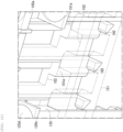
- FIG. 11 is a perspective view of the vicinity of the tip end of the leg portion in a gripping state of the gripping mechanism according to the embodiment as viewed from a rear side.
- FIG. 12 is a perspective view of the vicinity of the support groove 102 of the frame portion (support portion) 101 in the gripping state.
- FIG. 13 is a partially see-through perspective view of the vicinity of the longitudinal position regulation portion in the gripping state according to the embodiment.
- the longitudinal regulation protrusion 192 is inserted into any one of the plurality of longitudinal regulation recessed portions 191. Further, when the tip end 120a of the transverse biasing portion 123 and the tip end 130a of the transverse biasing portion 133 move by the relative movement distance Tx, the gripping is performed.
- the embodiment is different from the first and second embodiments in that a gripping mechanism is provided in a robot.
- Other corresponding components are assigned the same reference signs and the description thereof is omitted.
- a weight of the gripping mechanism is 200g to 400g.
- the material of the transverse moving frame portion 151 is ABS resin.
- the material of the fixed frame portion 101A is ABS resin.
- the material of the rack 155c is ABS resin.
- handling of objects on a production line includes, for example,
- utilization examples of serving as a robot leg include
Landscapes
- Engineering & Computer Science (AREA)
- Robotics (AREA)
- Mechanical Engineering (AREA)
- Manipulator (AREA)
Abstract
Description
- The present invention relates to a gripping mechanism and a robot, and in particular to a technique suitable for use in enabling gripping of an irregular surface.
- As a probe used on the ground and in an outer space, PTL 1 discloses a configuration including a leg or an arm and a gripping structure provided at an end portion of the leg or the arm. The gripping structure includes a plurality of claws, a plurality of elastic members having one end portion coupled to one of the plurality of claws and elastically deformable, and a support supporting the plurality of elastic members.
- Further, NPL 1 and NPL 2 disclose other examples of the configuration of a gripper.
- PTL 1:
WO2018/173250 -
- NPL 1: Uno, K., Takada, N., Okawara, T., Haji, K., Candalot, A., Ribeiro, W. F., ... & Yoshida, K. (2021, July). Hubrobo: a lightweight multi-limbed climbing robot for exploration in challenging terrain. In 2020 IEEE-RAS 20th International Conference on Humanoid Robots (Humanoids) (pp. 209-215). IEEE.
- NPL 2: Nagaoka, K., Minote, H., Maruya, K., Shirai, Y., Yoshida, K., Hakamada, T., Sawada, H., Kubota, T. (2018, Juanuary) Passive Spine Gripper for Free-Climbing Robot in Extreme Terrain, IEEE Robotics and Automation Letters. IEEE.
- However, since a gripping structure in the related art can only grip a protruding portion of an object to be gripped having an uneven shape, there was a problem that it was not possible to obtain a reliable grip for various uneven shapes. Further, on uneven ground close to being vertical, an overhanging lower side surface, or the like, there is a problem that a gripping force may be insufficient to obtain a reliable grip for the uneven shape.
- The invention has been made in view of the above circumstances, and an object of the invention is to provide a gripping mechanism and a robot capable of reliably gripping a recessed portion in addition to a protruding portion in handling an uneven shape of an irregular surface with a simple configuration.
-
- (1) In order to solve the above problems, a gripping mechanism according to an aspect of the invention is a gripping mechanism that takes an uneven surface having an irregular shape as an object to be gripped, the gripping mechanism including:
- a plurality of leg portions extending in a longitudinal direction and arranged in a transverse direction intersecting the longitudinal direction; and
- a support portion supporting each leg portion such that the leg portion is able to reciprocate independently in the longitudinal direction, in which
- the leg portion includes a set of divided leg portions that are divided in a front-rear direction intersecting the longitudinal direction and the transverse direction and that are adjacent to each other in the front-rear direction, and
- the support portion includes
- a transverse moving portion configured to relatively move each set of the divided leg portions in the transverse direction, and
- a longitudinal biasing portion configured to bias the leg portion in the longitudinal direction.
- (2) The gripping mechanism of the invention according to the above (1), in which
the transverse moving portion may relatively move each set of the divided leg portions in the transverse direction by a same distance in the plurality of leg portions. - (3) The gripping mechanism of the invention according to the above (1), in which
- the plurality of leg portions arranged in the transverse direction may be arranged in a plurality of rows in the front-rear direction, and
- the transverse moving portion may relatively move each row of the divided leg portions by a same distance in the transverse direction.
- (4) The gripping mechanism of the invention according to the above (1), in which
the leg portion- may include a contact portion, which is possible to come into contact with an object to be gripped, at a position in the transverse direction at a tip end of the divided leg portion, and
- may be provided with a transverse biasing portion configured to bias the contact portion in the transverse direction.
- (5) The gripping mechanism of the invention according to the above (1), further including:
a longitudinal position regulation portion configured to regulate a longitudinal position of the leg portion when the divided leg portion is moved relatively in the transverse direction by the transverse moving portion. - (6) A robot according to another aspect of the invention including:
- the gripping mechanism according to any one of the above (1) to (5); and
- an arm whose tip end is provided with the gripping mechanism.
- (1) The gripping mechanism according to an aspect of the invention has the configuration of the above (1).
- According to this configuration, the plurality of leg portions supported by the support portion so as to be regulated from moving in the longitudinal direction independently move in the longitudinal direction. Accordingly, in the gripping mechanism positioned facing the uneven surface having an irregular shape, tip ends of the leg portions come to fit the shape of the uneven surface by adapting to the shape of the uneven surface by the biasing member. In this state, the divided leg portions driven by the transverse moving portion move so as to be separated from each other in the transverse direction, so that the tip ends of the plurality of divided leg portions come into contact with a recessed portion or a protrusion of the uneven surface having an irregular shape from the transverse direction.
- At this time, the tip ends of the divided leg portions in sets adjacent or not adjacent to each other correspondingly come to sandwich the protrusion of the uneven surface in case of protrusion or press to stretch out the recessed portion of the uneven surface in case of recessed portion. Accordingly, it is possible to grip the uneven surface having an irregular shape with the gripping mechanism.
- Further, the divided leg portions driven by the transverse moving portion in the gripping state move so as to return to their original positions in the transverse direction, so that the tip ends of the plurality of divided leg portions are separated from the recessed portion or protrusion of the uneven surface having an irregular shape from the transverse direction. Accordingly, it is possible to release the uneven surface having an irregular shape from the grip of the gripping mechanism. Therefore, it is easy to reliably perform holding of the gripping mechanism to an uneven surface having an irregular shape or support for an object having an uneven surface having an irregular shape by the gripping mechanism and release of the holding and the support.
- Moreover, since gripping and release are possible by just moving the divided leg portion in the transverse direction, which is one direction, by the transverse moving portion, only a single drive mechanism is required, and this operation can be implemented at low cost with a simple lightweight configuration and maintaining high operation reliability.
- The longitudinal direction, the transverse direction, and the front-rear direction are not limited to an advancing direction of the gripping mechanism or a gravity direction as long as being intersecting with one another.
- A configuration of the biasing member is not limited as long as the biasing force can be applied, and various configurations may be adopted.
- (2) The gripping mechanism of the invention according to the above (1) has the configuration of the above (2).
- According to this configuration, in the plurality of leg portions, the divided leg portions of the respective sets move relatively in the transverse direction by the same distance so that the tip ends of the plurality of divided leg portions come into contact with the recessed portion or the protrusion of the uneven surface having an irregular shape from the transverse direction. At this time, regardless of whether the sets are adjacent to each other or not, the tip ends of the divided leg portions come to sandwich the protrusion of the uneven surface in case of protrusion or press to stretch out the recessed portion of the uneven surface in case of recessed portion correspondingly to the movement distance. That is, in accordance with the movement distance between the tip end of the moved divided leg portion and the tip end of the divided leg portion that is not moved, the tip ends press the uneven surface in contact in the transverse direction. Since all the divided leg portions are supported by the support portion and pressing forces in the transverse direction are opposed to each other, the gripping mechanism can grip the uneven surface having an irregular shape.
- Although divided leg portions that are not in contact with the uneven surface in the transverse direction do not contribute to the pressing force for gripping, since a plurality of leg portions are provided, the gripping can be performed even when there are divided leg portions that are not in contact with the uneven surface.
- (3) The gripping mechanism of the invention according to the above (1) or (2) has the configuration of the above (3).
- According to this configuration, in the leg portions arranged in a plurality of rows in the transverse direction and the front-rear direction, the divided leg portions can be relatively moved in the transverse direction by the same distance in all the sets. Accordingly, in a range in which the leg portions are arranged in a plurality of rows in the transverse direction and the front-rear direction, a large number of leg portions can be brought into contact with the recessed portion or protrusion of the uneven surface having an irregular shape from the transverse direction. Accordingly, it is possible to grip the uneven surface in a wider range in correspondence with the shape of the uneven surface, and thus it is possible to perform more reliable gripping.
- (4) The gripping mechanism of the invention according to any one of the above (1) to (3) has the configuration of the above (4).
- According to this configuration, when the contact portion at the tip end of the leg portion is brought into contact with the uneven surface having an irregular shape from the transverse direction, a large number of leg portions can be brought into contact with the recessed portion or the protrusion on the uneven surface from the transverse direction in a state where the contact portion is biased by the transverse biasing portion. Accordingly, in accordance with the shape of the uneven surface, it is possible to sandwich the protrusion of the uneven surface by the biased contact portions in case of protrusion and press to stretch out the recessed portion by the biased contact portions in case of recessed portion. Accordingly, it is possible to obtain a grip in accordance with the shape of the uneven surface more accurately, and thus it is possible to obtain a more reliable grip.
- The transverse biasing portion may be formed of an elastic member having a plate shape. Alternatively, the transverse biasing portion may be implemented as a configuration in which a tip end portion, which is rotatable around a rotation shaft provided in the divided leg portion and extending in the front-rear direction, is provided and can be biased in the transverse direction by a predetermined actuator or the like. In this case, the actuator can apply a biasing force to each of the leg portions or each of the divided leg portions independently, can apply a biasing force to a plurality of leg portions or divided leg portions collectively, or can apply all the biasing forces equally.
- (5) The gripping mechanism of the invention according to any one of the above (1) to (4) has the configuration of the above (5).
- According to this configuration, when the divided leg portions move relatively in the transverse direction and a distance of the relative movement is the maximum, the longitudinal position regulation portion regulates the longitudinal position of the leg portion. Accordingly, the leg portions at different longitudinal positions are held so as not to move in the longitudinal direction, and the divided leg portions moved in the transverse direction or the leg portions in the sets of the divided leg portions can maintain the position in the longitudinal direction required in the gripping state. Accordingly, even if a force in the longitudinal direction acts on the leg portion that grips the uneven surface in the gripping state, the state is maintained and the gripping is not released.
- Further, by simply moving the divided leg portions so as to reduce the relative distance in the transverse direction, it is possible to release the longitudinal position regulation of the leg portion posed by the longitudinal position regulation portion.
- Specifically, a plurality of longitudinal regulation recessed portions may be formed in the longitudinal direction at a position on the front side of the divided leg portion that moves so as to increase the relative distance in the transverse direction, and a longitudinal regulation protrusion corresponding to the longitudinal regulation recessed portion may be formed in the transverse moving portion at a position close to the divided leg portion that does not move. Further, the longitudinal regulation recessed portion and the longitudinal regulation protrusion may be engaged with each other when the divided leg portions move relatively in the transverse direction and the distance of the relative movement is the maximum, and may be disengaged when the relative movement distance of the divided leg portions in the transverse direction is reduced.
- (6) The robot according to another aspect of the invention has the configuration of the above (6).
- According to this configuration, by repeating the gripping and release of the uneven surface by the gripping mechanism according to any one of the above configurations, a gripping force sufficient to support the own weight of the robot can be presented even on an uneven surface, in particular, uneven ground close to being vertical, an overhanging lower side surface or the like, and a reliable grip can be obtained.
- (7) The gripping mechanism of the invention according to any one of the above (1) to (5) may have a configuration in which the leg portion includes a divided longitudinal position maintaining portion that causes the divided leg portions, which are in a set, to be at the same position in the longitudinal direction by the longitudinal biasing portion.
- According to this configuration, when the leg portion is biased in the longitudinal direction by the longitudinal biasing portion, the divided leg portions in a set can be maintained at the same position in the longitudinal direction by the divided longitudinal position maintaining portion. Specifically, the divided longitudinal position maintaining portion can ensure that a relative position of the divided leg portions in a set in the longitudinal direction do not change even when the leg portion moves in the longitudinal direction, and that the relative position of the divided leg portions in the longitudinal direction do not change even when the leg portion moves in the transverse direction by the transverse moving portion.
- (8) The gripping mechanism of the invention according to any one of the above (1) to (5) and (7) may have a configuration in which the longitudinal biasing portion includes a longitudinal detection unit that detects a position of the leg portion in the longitudinal direction.
- According to this configuration, when a plurality of leg portions move in the longitudinal direction independently of each other, the tip ends of the plurality of leg portions come into contact with the uneven surface having an irregular shape and adapt to the uneven shape, and when the longitudinal position is changed in each leg portion, a biasing force corresponding to the shape of the uneven surface is applied to the longitudinal detection unit by the biasing force of the longitudinal biasing portion in each leg portion. The longitudinal detection unit outputs the biasing force and the outputs of the respective leg portions are compared, whereby it is possible to estimate the shape of the uneven surface by using the gripping mechanism as a shaping gauge by only bringing the gripping mechanism into contact with the uneven surface to an extent that the leg portions are longitudinally moved.
- That is, with the gripping mechanism, the shape of the uneven surface can be estimated (recognized) by the contact with both the recessed portion and the protrusion, the shape of the uneven surface can be griped through both the recessed portion and the protrusion, and further the estimation and gripping can be performed at the same time. Moreover, the estimation and gripping can be enabled without providing a complicated control mechanism, an optical mechanism for acquiring visual information, or the like.
- (9) The gripping mechanism of the invention according to any one of the above (1) to (5), (7) or (8) may have a configuration in which
- for an arrangement pitch Px of the leg portions in the transverse direction and a relative movement distance Tx of the divided leg portions in the transverse direction, a value of a ratio Tx/Px is in a range of

- For example,


- (10) The gripping mechanism of the invention according to any one of the above (1) to (5) and (7) to (9) may have a configuration in which
- for a longitudinal movable distance Kz in which the leg portion is movable with respect to the support portion by the longitudinal biasing portion in the longitudinal direction and a support length Wz at which the leg portion is supported by the transverse moving portion in the longitudinal direction, a value of a ratio Kz/Wz is in a range of

- For example,


- (11) The gripping mechanism of the invention according to in any one of the above (1) to (5) and (7) to (10) may have a configuration in which
- the plurality of leg portions arranged in the transverse direction are arranged in a plurality of rows in the front-rear direction, and
- for an arrangement pitch Py of the leg portions in the front-rear direction and a relative movement distance Tx of the divided leg portion in the transverse direction, a value of a ratio Tx/Py is in a range of

- For example,


- (12) The gripping mechanism of the invention according to any one of the above (1) to (5) and (7) to (11) may have a configuration in which
- the leg portion
- includes a contact portion, which is possible to come into contact with an object to be gripped, at a position in the transverse direction at a tip end of the divided leg portion, and
- is provided with a transverse biasing portion configured to bias the contact portion in the transverse direction,
- the transverse biasing portion is an elastic plate body, and
- for a longitudinal length Fz of the transverse biasing portion and a longitudinal movable distance Kz in which the leg portion is movable with respect to the support portion by the longitudinal biasing portion in the longitudinal direction, a value of a ratio Kz/Fz is in a range of

- For example,


- (13) The gripping mechanism of the invention according to any one of the above (1) to (5) and (7) to (12) may have a configuration in which
- the leg portion
- includes a contact portion, which is possible to come into contact with an object to be gripped, at a position in the transverse direction at a tip end of the divided leg portion, and
- is provided with a transverse biasing portion configured to bias the contact portion in the transverse direction,
- the transverse biasing portion is an elastic plate body, and
- for a longitudinal length Fz of the transverse biasing portion and a relative movement distance Tx of the divided leg portion in the transverse direction, a value of a ratio Tx/Fz is in a range of

- For example,


- According to the invention, it is possible to provide a gripping mechanism and a robot capable of gripping not only a protrusion but also a recessed portion on an irregular surface by a simple configuration to enable a reliable grip sufficiently corresponding to the uneven shape.
-
- [
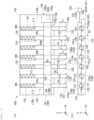
FIG. 1] FIG. 1 is a schematic diagram illustrating a gripping mechanism according to a first embodiment of the invention, in which (a) is a front view and (b) is a bottom view. - [
FIG. 2] FIG. 2 is a schematic diagram illustrating a state in which the gripping mechanism according to the first embodiment of the invention is in contact with an uneven surface, in which (a) is a front view and (b) is a bottom view. - [
FIG. 3] FIG. 3 is a schematic diagram illustrating a state in which an uneven surface is gripped by the gripping mechanism according to the first embodiment of the invention, in which (a) is a front view and (b) is a bottom view. - [
FIG. 4] FIG. 4 is a bottom view illustrating another example of the gripping mechanism according to the first embodiment of the invention. - [
FIG. 5] FIG. 5 is a bottom view illustrating another example of the first embodiment of the gripping mechanism according to the invention. - [
FIG. 6] FIG. 6 is a perspective view of a gripping mechanism according to a second embodiment of the invention as viewed from the front. - [
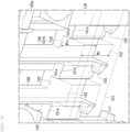
FIG. 7] FIG. 7 is a perspective view of the vicinity of a tip end of a leg in the gripping mechanism according to the second embodiment of the invention. - [
FIG. 8] FIG. 8 is a perspective view of the vicinity of a support groove of a support portion in the gripping mechanism according to the second embodiment of the invention. - [
FIG. 9] FIG. 9 is an exploded view of a divided leg portion of the gripping mechanism according to the second embodiment of the invention as viewed from a front surface and a rear surface. - [
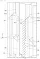
FIG. 10] FIG. 10 is a partially see-through perspective view of the vicinity of a longitudinal position regulation portion in the gripping mechanism according to the second embodiment of the invention. - [
FIG. 11] FIG. 11 is a perspective view of the vicinity of the tip end of the leg portion in a gripping state of the gripping mechanism according to the second embodiment of the invention. - [
FIG. 12] FIG. 12 is a perspective view of the vicinity of the support groove of the support portion in a gripping state of the gripping mechanism according to the second embodiment of the invention. - [
FIG. 13] FIG. 13 is a partially see-through perspective view of the vicinity of the longitudinal position regulation portion in a gripping state of the gripping mechanism according to the second embodiment of the invention. - [
FIG. 14] FIG. 14 is an exploded view of another example of the divided leg portion in the gripping mechanism according to the second embodiment of the invention as viewed from a front surface and a rear surface. - [
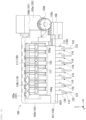
FIG. 15] FIG. 15 is a schematic diagram illustrating a third embodiment of a robot including a gripping mechanism according to the invention. - [
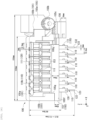
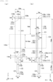
FIG. 16] FIG. 16 is a diagram illustrating dimensions corresponding to the gripping mechanism of the second embodiment, as an example of the invention. - [
FIG. 17] FIG. 17 is a diagram illustrating dimensions corresponding to the gripping mechanism of the second embodiment, as an example of the invention. - [
FIG. 18] FIG. 18 is a diagram illustrating dimensions corresponding to the gripping mechanism of the second embodiment, as an example of the invention. - Hereinafter, a first embodiment of a gripping mechanism according to the invention will be described with reference to the drawings.
-
FIG. 1 is a schematic diagram illustrating a gripping mechanism according to the embodiment. In the drawing, areference numeral 100 denotes the gripping mechanism. - In the following description, a longitudinal direction in which a leg portion extends is defined as a Z direction, and a transverse direction orthogonal to the Z direction is defined as an X direction. A front-rear direction orthogonal to the X direction and the Z direction is defined as a Y direction. The X direction, the Y direction, and the Z direction are used in the description of the gripping mechanism, and have different implication from a longitudinal direction and a horizontal direction corresponding to gravity with respect to an uneven surface to be griped by the gripping mechanism. The X direction, the Y direction, and the Z direction may not coincide with the longitudinal direction or the horizontal direction.
- The
gripping mechanism 100 according to the embodiment takes an uneven surface S (seeFIG. 2 ) having an irregular shape as an object to be gripped. - As illustrated in
FIG. 1 , thegripping mechanism 100 according to the embodiment includes a frame portion (support portion) 101, a plurality ofleg portions 110 supported by theframe portion 101, a transverse movingportion 150, alongitudinal biasing portion 170, and alongitudinal detection unit 180. - Each of the plurality of
leg portions 110 extends in the Z direction. The plurality ofleg portions 110 are separated from one another in the X direction. A separation distance (arrangement pitch) Px of the plurality ofleg portions 110 in the X direction is equal between anyadjacent leg portions 110. The plurality ofleg portions 110 are arranged parallel to one another. - Since the plurality of
leg portions 110 have the same structure, oneleg portion 110 will be described hereinafter. - The
leg portion 110 is rod-shaped having a substantially rectangular cross section. Theleg portion 110 extends in the longitudinal direction (Z direction). Atip end 110a of theleg portion 110 in the longitudinal direction (Z direction) is positioned outside theframe portion 101. In the plurality ofleg portions 110, the tip ends 110a protrude outward by the same length from theframe portion 101 in a state where thegripping mechanism 100 is not in contact with the uneven surface S. - As illustrated in (b) of
FIG. 1 , theleg portion 110 is longitudinally divided into two in the front-rear direction (Y direction) and includes a set of a static divided leg portion (divided leg portion) 120 and a dynamic divided leg portion (divided leg portion) 130. The static divided leg portion (divided leg portion) 120 and the dynamic divided leg portion (divided leg portion) 130 have substantially the same rectangular cross section on an XY plane, and are not limited to this shape. The static dividedleg portion 120 and the dynamic dividedleg portion 130 have substantially the same rectangular shape as viewed in the Y direction, and are not limited to this shape. The static dividedleg portion 120 and the dynamic dividedleg portion 130 are arranged adjacent to each other in the Y direction. - A surface of the static divided
leg portion 120 and a surface of the dynamic dividedleg portion 130 facing each other are defined as divided slidingsurfaces surfaces - Here, as will be described later, "static" and "dynamic" are adopted in names of the divided
leg portions - Further, a configuration may be implemented in which the static divided
leg portion 120 and the dynamic dividedleg portion 130 are driven simultaneously in the X direction. In this case, similar to the transverse movingportion 150 for the dynamic dividedleg portion 130, a configuration for driving like the transverse moving portion can be provided for the static dividedleg portion 120. In this case, it is possible to separately drive the static dividedleg portion 120 and the dynamic dividedleg portion 130 and to simultaneously drive the static dividedleg portion 120 and the dynamic dividedleg portion 130. - In a case of simultaneously driving the static divided
leg portion 120 and the dynamic dividedleg portion 130, it is preferable to provide a mechanism capable of driving the static dividedleg portion 120 and the dynamic dividedleg portion 130 to separate from each other simultaneously in the X direction or driving the static dividedleg portion 120 and the dynamic dividedleg portion 130 to approach each other simultaneously in the X direction. Further, in the case of simultaneously driving the static dividedleg portion 120 and the dynamic dividedleg portion 130, a configuration is preferably implemented in which operations of the static dividedleg portion 120 and the dynamic dividedleg portion 130 are synchronized. - A
static contact portion 122 is formed at a position in the X direction of a peripheral side surface of atip end 120a of the static dividedleg portion 120. Thestatic contact portion 122 may protrude in the X direction from the peripheral side surface of thetip end 120a of the static dividedleg portion 120. Thestatic contact portion 122 can come into contact with the object to be gripped. The shape, material, hardness, elasticity, and the like of thestatic contact portion 122 can be selected according to characteristics of the object to be gripped. - For example, when the object to be griped is a hard uneven surface of a rock or the like, it is possible to form the
static contact portion 122 as a pin (needle) that is made of metal and has a pointed tip end for contact. - Alternatively, when the object to be griped is a material having flexibility or having resilience and elasticity, the
static contact portion 122 can be made of a material having elasticity such as silicone resin and can be deformed according to the shape of the object to be griped. In this case, a portion of thestatic contact portion 122 facing the object to be griped may have a flat surface portion, may be a spherical surface whose center is protruding toward the object to be griped or a curved surface or conical surface equivalent to the spherical surface, or may be a spherical surface whose center is recessed against the object to be gripped or a curved surface, conical surface or a recess having a flat bottom surface equivalent to the spherical surface. - Further, when the object to be griped is a rock or the like, a metal needle or the like can be used as the material of the
static contact portion 122. Alternatively, a silicone resin or the like can be used as the material of thestatic contact portion 122 depending on the various materials of the object to be griped, such as metal, plastic, and rubber. - A
dynamic contact portion 132 is formed at a position in the X direction of a peripheral side surface of atip end 130a of the dynamic dividedleg portion 130. Thedynamic contact portion 132 may protrude in the X direction from the peripheral side surface of thetip end 130a of the dynamic dividedleg portion 130. Thedynamic contact portion 132 can come into contact with the object to be gripped. The shape, material, hardness, elasticity, and the like of thedynamic contact portion 132 can be selected according to the characteristics of the object to be gripped. - Similarly to the above-described
static contact portion 122, thedynamic contact portion 132 can also adopt various configurations. As will be described later, thedynamic contact portion 132 is provided at a position on the front side in a moving direction of the dynamic dividedleg portion 130 when being driven in the X direction so that the static dividedleg portion 120 and the dynamic dividedleg portion 130 are separated from each other. - The
dynamic contact portion 132 and thestatic contact portion 122 have substantially the same configuration, and protruding directions thereof are opposite to each other in the X direction. Here, the protrusion means extending in a direction away from an axis in the Z direction of the static dividedleg portion 120 and the dynamic dividedleg portion 130. - The
dynamic contact portion 132 and thestatic contact portion 122 are formed at the same position in the Z direction. This is to achieve a state where reaction forces are close to being on the same straight line as much as possible when thedynamic contact portion 132 and thestatic contact portion 122 press the object to be griped, as will be described later. Depending on an uneven shape of the object to be gripped, a configuration in which thedynamic contact portion 132 and thestatic contact portion 122 are close to the tip ends 130a and 120a as much as possible in the Z direction may be preferred and a configuration in which thedynamic contact portion 132 and thestatic contact portion 122 are separated from the tip ends 130a and 120a by a predetermined Z-direction length may be preferred. - The
dynamic contact portion 132 and thestatic contact portion 122 are formed in point-symmetry with respect to a center of theleg portion 110 with respect to the divided slidingsurfaces surfaces - The
dynamic contact portion 132 and thestatic contact portion 122 are separated from each other in the X direction by the same amount as an X direction dimension of each of thetip end 120a of the static dividedleg portion 120 and thetip end 130a of the dynamic dividedleg portion 130. - The
dynamic contact portion 132 and thestatic contact portion 122 are biased in the transverse direction by atransverse biasing portion 133 and atransverse biasing portion 123, respectively. - The
transverse biasing portion 133 and thetransverse biasing portion 123 can be implemented by an elastic member having a predetermined Z-direction length Fz from thetip end 130a and thetip end 120a toward abase end 110b of theleg portion 110. - The
transverse biasing portion 133 absorbs displacement of thedynamic contact portion 132 in the X direction when thedynamic contact portion 132 comes into contact with the uneven surface S that is an object to be gripped. At the same time, thetransverse biasing portion 133 allows thedynamic contact portion 132 to press the uneven surface S in the X direction to an extent that the uneven surface S can be gripped. - Similarly to the
dynamic contact portion 132, in the case of thestatic contact portion 122, thetransverse biasing portion 123 also absorbs displacement of thestatic contact portion 122 in the X direction when thestatic contact portion 122 comes into contact with the uneven surface S that is an object to be gripped. At the same time, thetransverse biasing portion 123 allows thestatic contact portion 122 to press the uneven surface S in the X direction to an extent that the uneven surface S can be gripped. - The
transverse biasing portion 133 and thetransverse biasing portion 123 may be formed to be thinner than a thickness (X-direction width dimension) of a position close to thebase end 110b of theleg portion 110, differently from an X-direction width dimension illustrated in the drawings. - Further, the
transverse biasing portion 133 and thetransverse biasing portion 123 are not limited to this configuration as long as thetransverse biasing portion 133 and thetransverse biasing portion 123 can bias thedynamic contact portion 132 and thestatic contact portion 122 in the X direction. - Positions of the static divided
leg portion 120 and the dynamic dividedleg portion 130 in the Z direction are restricted by a divided longitudinalposition maintaining portion 111. The divided longitudinalposition maintaining portion 111 can be, for example, a step that extends in the X direction and is formed corresponding to each of the divided slidingsurfaces base end 110b of theleg portion 110. Alternatively, the divided longitudinalposition maintaining portion 111 may be formed as a pair of a groove and a projection on the divided slidingsurfaces - By maintaining a state in which the divided longitudinal
position maintaining portions 111 engage with each other, the positions of the static dividedleg portion 120 and the dynamic dividedleg portion 130 in the Z direction are maintained in a state where a relative position thereof can be changed in the X direction. - Accordingly, even when a Z direction position of the
leg portion 110 is changed, a state can be maintained where the static dividedleg portion 120 and the dynamic dividedleg portion 130 in a pair are not displaced in the Z direction. - When a step extending in the X direction is formed as the divided longitudinal
position maintaining portion 111, it is possible to further provide a step extending in the X direction formed correspondingly to each of the divided slidingsurfaces tip end 110a of theleg portion 110. - Alternatively, when the divided longitudinal
position maintaining portion 111 is formed as a pair of a groove and a projection on the divided slidingsurfaces surfaces - Each of the plurality of
leg portions 110 is supported by the frame portion (support portion) 101 at amiddle portion 110c that is at the middle in the Z direction. In a fixedframe portion 101A of theframe portion 101, a plurality of static frame grooves (support grooves) 102 extending in the Z direction are formed on a slidingsurface 101a extending along a ZX plane. The slidingsurface 101a extends in the X direction and has a predetermined length W1z in the Z direction. - The
static frame grooves 102 are formed so as to be parallel to each other at positions separated in the X direction, corresponding to the number of theleg portions 110. Thestatic frame groove 102 has a length W1z in the Z direction equal to the length (width dimension) W1z of the slidingsurface 101a in the Z direction. The lengths W1z of the plurality ofstatic frame grooves 102 in the Z direction are all equal. - A distance at which the plurality of
static frame grooves 102 are separated from each other in the X direction, that is, an arrangement interval of thestatic frame grooves 102 is equal to an arrangement pitch Px of theleg portions 110. - The
static frame grooves 102 accommodate the static dividedleg portions 120 of theleg portions 110, respectively. The static dividedleg portion 120 accommodated in thestatic frame groove 102 is movable in the Z direction, and movements thereof in the X direction and Y direction are restricted by the shape of thestatic frame groove 102. A depth of thestatic frame groove 102 in the Y direction is equal to a thickness dimension of the static dividedleg portion 120 in the Y direction at themiddle portion 110c. At this time, the divided slidingsurface 121 is flush with the slidingsurface 101a. - A sliding
surface 151a of a transverse movingframe portion 151 is in contact with the slidingsurface 101a of the fixedframe portion 101A. - The transverse moving
frame portion 151 constitutes a support portion. The transverse movingframe portion 151 extends in the X direction. The transverse movingframe portion 151 has a substantially rectangular cross-sectional shape along a YZ plane. The transverse movingframe portion 151 can reciprocate in the X direction with respect to the fixedframe portion 101A. The transverse movingframe portion 151 does not move in the Y direction or the z direction with respect to theframe portion 101. - The transverse moving
frame portion 151 has a length (width dimension) Wz in the Z direction that is equal to or slightly smaller than the length (width dimension) W1z of the slidingsurface 101a in the Z direction. A plurality ofdynamic frame grooves 153 extending in the Z direction are formed on the slidingsurface 151a of the transverse movingframe portion 151, correspondingly to thestatic frame grooves 102 of the slidingsurface 101a. Similarly to the slidingsurface 101a, the slidingsurface 151a extends in the X direction and has a predetermined length Wz in the Z direction. - Similarly to the
static frame grooves 102, thedynamic frame grooves 153 are formed so as to be parallel to each other at positions separated in the X direction, corresponding to the number of theleg portions 110. The dynamic frame groove (support groove) 153 has a length Wz in the Z direction equal to the length (width dimension) Wz of the slidingsurface 151a in the Z direction. The lengths Wz of the plurality ofdynamic frame grooves 153 in the Z direction are all equal. - A distance at which the plurality of
dynamic frame grooves 153 are separated from each other in the X direction, that is, an arrangement interval of thedynamic frame grooves 153 is equal to the arrangement pitch Px of theleg portions 110. - The
dynamic frame grooves 153 accommodate the dynamic dividedleg portions 130 of theleg portions 110, respectively. The dynamic dividedleg portion 130 accommodated in thedynamic frame groove 153 is movable in the Z direction, and movements thereof in the X direction and Y direction are restricted by the shape of thedynamic frame groove 153. A depth of thedynamic frame groove 153 in the Y direction is equal to a thickness dimension of the dynamic dividedleg portion 130 in the Y direction at themiddle portion 110c. At this time, the divided slidingsurface 131 is flush with the slidingsurface 151a. - The transverse moving
frame portion 151 constitutes the transverse movingportion 150. - The transverse moving
portion 150 can reciprocate the plurality of dynamic dividedleg portions 130 in the X direction. The transverse movingportion 150 includes the transverse movingframe portion 151, a transversemovement drive unit 155 that reciprocates the transverse movingframe portion 151 in the X direction, and aconnection portion 156 that connects the transverse movingframe portion 151 and the transversemovement drive unit 155. The transversemovement drive unit 155 includes amotor 155a serving as a drive source, apinion 155b rotated by themotor 155a, and arack 155c meshing with thepinion 155b and capable of reciprocating in the X direction. Therack 155c can be integrated with theconnection portion 156. - The transverse moving
portion 150 rotates thepinion 155b by driving of thedrive source 155a such as a motor in the transversemovement drive unit 155, and operates therack 155c in the X direction, which meshes with theopinion 155b, by the rotation of thepinion 155b. By the operation of therack 155c in the X direction, the transverse movingframe portion 151 integrally connected to therack 155c and theconnection portion 156 can reciprocate in the X direction in a reciprocating manner. - Along with the reciprocating operation of the transverse moving
frame portion 151 in the X direction, the plurality of dynamic dividedleg portions 130 accommodated in thedynamic frame grooves 153 reciprocate in the X direction integrally with the transverse movingframe portion 151. At this time, the plurality of dynamic dividedleg portions 130 can perform the same movement in the X direction. In addition, in the movement of the transverse movingframe portion 151 in the X direction, it is possible to maintain a state in which the operation of the dynamic dividedleg portion 130 in the Z direction and the Y direction is not affected. - Further, before the dynamic divided
leg portion 130 moves in the X direction, thedynamic frame groove 153 and thestatic frame groove 102 are aligned in a manner of overlapping each other as viewed in the Y direction. Accordingly, before the dynamic dividedleg portion 130 moves in the X direction, the divided slidingsurface 131 is in contact with only the divided slidingsurface 121. Before the dynamic dividedleg portion 130 moves in the X direction, the slidingsurface 151a is in contact with only the slidingsurface 101a. - When the dynamic divided
leg portion 130 moves in the X direction, the divided slidingsurface 131 comes into contact with the divided slidingsurface 121 and the slidingsurface 101a. Similarly, before the dynamic dividedleg portion 130 moves in the X direction, the divided slidingsurface 121 is in contact with only the divided slidingsurface 131. When the dynamic dividedleg portion 130 moves in the X direction, the divided slidingsurface 121 comes into contact with the divided slidingsurface 131 and the slidingsurface 151a. - At this time, since the divided sliding
surface 131 is flush with the slidingsurface 151a and the divided slidingsurface 121 is flush with the slidingsurface 101a, the movement of the divided slidingsurface 131 and divided slidingsurface 121 in the X direction is not hindered by the slidingsurface 151a and the slidingsurface 101a. - The
longitudinal biasing portion 170 is disposed in contact with thebase end 110b of theleg portion 110. - The
longitudinal biasing portion 170 biases theleg portion 110 in the Z direction. Eachlongitudinal biasing portion 170 biases thecorresponding leg portions 110 independently. Thelongitudinal biasing portion 170 may be implemented by an elastic member such as a spring disposed between theframe portion 101 and thebase end 110b of theleg portion 110. A longitudinal movable distance Kz in the Z direction of theleg portion 110 based on expansion and contraction of thelongitudinal biasing portion 170 can be set (seeFIG. 2 ). - Further, the
longitudinal detection unit 180 is disposed between thelongitudinal biasing portion 170 and theframe portion 101. Thelongitudinal detection unit 180 is, for example, a pressure sensor. In this case, the pressure sensor can detect a pressing force, by which thelongitudinal biasing portion 170 presses thelongitudinal detection unit 180, in response to a change in a Z-direction position of thebase end 110b of theleg portion 110. - The Z-direction position of the
leg portion 110 can be changed by a biasing force of thelongitudinal biasing portion 170. When thetip end 110a of theleg portion 110 comes into contact with the object to be gripped such as the uneven surface S, theleg portion 110 is displaced in the Z direction corresponding to the uneven shape thereof. At this time, since thetip end 110a is biased by the biasing force of thelongitudinal biasing portion 170 toward the object to be gripped, a Z-direction position of thetip end 110a follows a Z-direction position of the object to be gripped such as the uneven surface S. Accordingly, thebase end 110b of theleg portion 110 follows the Z-direction position corresponding to the Z-direction position of the object to be gripped such as the uneven surface S. - The biasing force of the
longitudinal biasing portion 170 increases or decreases in accordance with the Z-direction position of theleg portion 110. That is, in a case where the Z-direction position of thetip end 110a is closer to the transverse movingframe portion 151 in the Z direction than when thetip end 110a is spaced apart from the transverse movingframe portion 151 in the Z direction, the biasing force of thelongitudinal biasing portion 170 is larger. Similarly, in a case where the Z-direction position of thebase end 110b is closer to the transverse movingframe portion 151 in the Z direction than when thetip end 110b is spaced apart from the transverse movingframe portion 151 in the Z direction, the biasing force of thelongitudinal biasing portion 170 is smaller. - In response to the increase or decrease in the biasing force of the
longitudinal biasing portion 170, an output from thelongitudinal detection unit 180 varies. By comparing the outputs collectively and referring to the position of thecorresponding leg portion 110 in the XY plane, it is possible to estimate distribution of a shape of the object to be gripped in the Z direction in the XY plane, that is, the uneven shape when the object to be gripped such as the uneven surface S is in contact with thetip end 110a. - The
longitudinal biasing portion 170 may be configured to be in contact with only the static dividedleg portion 120 at a position in contact with thebase end 110b of theleg portion 110. In this case, even when thelongitudinal biasing portion 170 biases the static dividedleg portion 120 in the Z direction, the dynamic dividedleg portion 130 can freely move in the X direction without being affected by the biasing force of thelongitudinal biasing portion 170. Therefore, at thebase end 110b of theleg portion 110, a contour shape presented byend portions 120b of the static dividedleg portions 120 along the XY plane can have a contour shape presented by theend portions 120b, which coincides with or larger than an end portion shape presented by thelongitudinal biasing portions 170 along the XY plane. - The
longitudinal biasing portion 170 is not limited to the above-described configuration as long as thelongitudinal biasing portion 170 can bias theleg portion 110 in the Z direction. - For example, a predetermined actuator that operates on a drive source such as a hydraulic pressure, an air pressure, or a motor may be employed as the
longitudinal biasing portion 170. In this case, it is possible to adopt a configuration in which Z-direction position control can be separately performed in theindividual leg portions 110. - Further, the
longitudinal detection unit 180 is not limited to the pressure sensor as long as the output can vary in accordance with the change in the Z-direction position of theleg portion 110. When a predetermined actuator is adopted as thelongitudinal biasing portion 170, it is possible to adopt a configuration in which the change in the Z-direction position of theleg portion 110 is detected by the operation of the actuator. - The
gripping mechanism 100 may include a longitudinalposition regulation portion 190. - Although not illustrated in detail in the embodiment, the longitudinal
position regulation portion 190 regulates a longitudinal position of theleg portion 110 when the dynamic dividedleg portion 130 moves relative to the static dividedleg portion 120 in the X direction by the transverse movingportion 150. - Specifically, as the longitudinal
position regulation portion 190, a plurality of longitudinal regulation recessedportion 191 recessed in the X direction are formed side by side in the Z direction at a Z-direction position corresponding to themiddle portion 110c of the dynamic dividedleg portion 130, which is also a position on the front side of the dynamic dividedleg portions 130 that move relatively in a shifted manner in the X direction. At the same time, alongitudinal regulation protrusion 192 can be formed in the fixedframe portion 101A that is in the vicinity of an opening position of thestatic frame groove 102 that is close to thetip end 110a. Thelongitudinal regulation protrusion 192 protrudes in the X direction toward the dynamic dividedleg portion 130 at a position closer to the transverse movingframe portion 151 than the slidingsurface 101a and can correspond to the longitudinal regulation recessedportion 191. - The
longitudinal regulation protrusion 192 is inserted into any one of the plurality of longitudinal regulation recessedportions 191 according to the Z-direction position of theleg portion 110 when the dynamic dividedleg portion 130 moves in the X direction. Accordingly, the longitudinal regulation recessedportion 191 and thelongitudinal regulation protrusion 192 are engaged with each other, and the Z-direction position of the dynamic dividedleg portion 130 is regulated with respect to theframe portion 101. In this state, as viewed in the Y direction, theleg portion 110 does not move in the Z direction until the dynamic dividedleg portion 130 returns to its original position in the X direction so as to align with the static dividedleg portion 120. - In the longitudinal
position regulation portion 190, both an X-direction depth of the plurality of longitudinal regulation recessedportions 191 and an X-direction protrusion dimension of thelongitudinal regulation protrusion 192 correspond to a relative movement distance Tx in the X direction between the dynamic dividedleg portion 130 and the static dividedleg portion 120. That is, the shapes of the plurality of longitudinal regulation recessedportions 191 and thelongitudinal regulation protrusion 192 can be configured such that when the dynamic dividedleg portion 130 moves in the X direction with respect to the static dividedleg portion 120 and a movement distance thereof is the maximum relative movement distance Tx, the mutual engagement is established, and when the relative movement distance between the dynamic dividedleg portion 130 and the static dividedleg portion 120 in the X direction is decreased by a predetermined amount from the relative movement distance Tx, the engagement is released (referring toFIG. 3 ). - In addition to the above configuration, the longitudinal
position regulation portion 190 may be formed of a material having a large friction such as a rubber pad, and the regulation can be achieved by a frictional force generated when pressing against the uneven surface S. - Hereinafter, an operation of the
gripping mechanism 100 according to the embodiment will be described. -
FIG. 2 is a schematic diagram illustrating a state in which the gripping mechanism according to the embodiment is in contact with an uneven surface.FIG. 3 is a schematic diagram illustrating a state in which an uneven surface is gripped by the gripping mechanism according to the embodiment. - In the
gripping mechanism 100 according to the embodiment, in a state before coming into contact with the uneven surface S as an object to be gripped, the Z-direction positions of all theleg portions 110 are the same with respect to theframe portion 101 as illustrated in (a) ofFIG. 1 . That is, the tip ends 110a of all theleg portions 110 are separated from the transverse movingframe portion 151 in the Z direction at the same distance. At this time, eachleg portion 110 is biased by thelongitudinal biasing portion 170 in a direction away from the transverse movingframe portion 151 in the Z direction. - In all the
leg portions 110, the static dividedleg portion 120 and the dynamic dividedleg portion 130 are located at positions overlapping each other as viewed in the Y direction. That is, thestatic frame groove 102 and thedynamic frame groove 153 in the X direction overlap each other as viewed in the Y direction. As illustrated in (b) ofFIG. 1 , in the transverse movingframe portion 151 facing the fixedframe portion 101A, an opening of thestatic frame groove 102 in the slidingsurface 101a and an opening of thedynamic frame groove 153 in the slidingsurface 151a align with each other and edge portions thereof are in contact with each other. That is, X-direction positions of the opening of thestatic frame groove 102 and the opening of thedynamic frame groove 153 coincide with each other. - In this state, the
gripping mechanism 100 is brought close to the uneven surface S. At this time, for example, thegripping mechanism 100 can be brought close to the uneven surface S along the Z direction. That is, thegripping mechanism 100 is brought close to the uneven surface S in the Z direction along theleg portion 110. This is because the uneven surface S has an irregular shape, and therefore thegripping mechanism 100 is brought close to the uneven surface S such that the axis of theleg portion 110 is not displaced, without taking into consideration the shape of the uneven surface S. - It is preferable to bring the
gripping mechanism 100 close to the uneven surface S in a state where theframe portion 101 is held and a thrust force is applied to theframe portion 101. - As a Z-direction distance between the
frame portion 101 and the uneven surface S decreases, thetip end 110a of theleg portion 110 comes into contact with the uneven surface S. At this time, although the time varies depending on a Z-direction shape of the uneven surface S at the position along the XY plane, in each of theleg portions 110, thetip end 110a of theleg portion 110 comes into contact with the uneven surface S in the order of a Z-direction distance between thetip end 110a and the uneven surface S decreasing. - For the
leg portion 110 whosetip end 110a comes into contact with the uneven surface S, theleg portion 110 moves toward the inside of theframe portion 101 as the Z-direction distance between theframe portion 101 and the uneven surface S decreases. That is, in accordance with the decrease in the Z-direction distance between theframe portion 101 and the uneven surface S, theleg portion 110 relatively moves in the Z direction such that thetip end 110a comes close to the transverse movingframe portion 151. Although there is a difference in time due to the position along the XY plane, theleg portion 110 whosetip end 110a is in contact with the uneven surface S moves in the Z direction relatively. - Here, the
leg portion 110 is accommodated inside a columnar space extending in the Z direction, which is formed by thestatic frame groove 102 and thedynamic frame groove 153. That is, the static dividedleg portion 120 is accommodated inside thestatic frame groove 102, and the dynamic dividedleg portion 130 is accommodated inside thedynamic frame groove 153. Further, opening edge portions of thestatic frame groove 102 and thedynamic frame groove 153 on the slidingsurfaces - Therefore, the
leg portion 110 is regulated from moving in the X direction and the Y direction and moves only in the Z direction. - When the
leg portion 110 moves in the Z direction, thelongitudinal biasing portion 170 is pressed in the Z direction. Thelongitudinal biasing portion 170 presses thelongitudinal detection unit 180 in the Z direction. At this time, a Z-direction length of thelongitudinal biasing portion 170 varies according to the magnitude of a Z-direction movement distance of theleg portion 110. Accordingly, the pressing force applied to thelongitudinal detection unit 180 increases or decreases. That is, the pressing force applied to thelongitudinal detection unit 180 increases or decreases according to the magnitude of the Z-direction movement distance of theleg portion 110. Thelongitudinal detection unit 180 as a press sensor outputs a detection result. At this time, it is preferable that information on the position along the XY plane of theleg portion 110 corresponding to the output can be determined simultaneously. - When the Z-direction distance between the
frame portion 101 and the uneven surface S decreases to a predetermined value, the approaching movement is stopped. This state is illustrated inFIG. 2 . In order to perform a gripping operation of thegripping mechanism 100, it is preferable that the tip ends 110a of all theleg portions 110 are in contact with the uneven surface S when the approaching movement is stopped. But it is conceivable that there is aleg portion 110 whosetip end 110a is not in contact with the uneven surface S depending on the uneven shape of the uneven surface S. - In stopping the approaching movement of the
gripping mechanism 100, it is possible to adopt a condition that there is aleg portion 110 that is moved in the Z direction to have a minimal expansion and contraction length of thelongitudinal biasing portion 170. In other words, in stopping the approaching movement of thegripping mechanism 100, it is possible to adopt a condition that there is aleg portion 110 of which the Z-direction movement distance is equal to the longitudinal movable distance Kz. In this case, the stop of the approaching movement can be achieved by adopting a condition that an output value from thelongitudinal detection unit 180 exceeds a predetermined set value. - Alternatively, a state in which a sum of the biasing forces of all the
longitudinal biasing portions 170 expanding and contracting according to the Z-direction position of the uneven surface along the XY plane and an own weight of thegripping mechanism 100 are balanced with each other may be adopted as a condition for stopping the approaching movement of thegripping mechanism 100. In this case, theframe portion 101 needs to be positioned higher in a gravity direction than the uneven surface S such that theleg portion 110 is retracted into theframe portion 101 by the own weight of thegripping mechanism 100. It is preferable that an approach drive actuator such as an arm capable of applying a pressing force, which acts similarly to the gravity in a direction in which thegripping mechanism 100 approaches the uneven surface S, to theframe portion 101 is connected. - Further, as a condition for stopping the approaching movement of the
gripping mechanism 100, a distance measuring mechanism capable of measuring an approach distance to the uneven surface S to be gripped may be provided at a position facing the uneven surface S to be gripped in theframe portion 101, and it is possible to stop the approach of thegripping mechanism 100 based on a measurement result. In this case, as the distance measuring mechanism, a distance measuring instrument using a sound wave, laser, or the like can be used as the measuring means. - Alternatively, as the distance measuring mechanism, a depth camera (camera with a depth measurement sensor such as stereo or ToF capable of visualizing, in a camera image, information on a distance to an object) can also be used.
- In
FIG. 2 , theleg portion 110 located at the center in a left-right direction is in a state where thetip end 110a thereof is not in contact with the uneven surface S. In (a) ofFIG. 2 , in thesecond leg portion 110 from the left, a Z-direction dimension of thelongitudinal biasing portion 170 is the smallest. Therefore, a difference in the Z-direction position of thetip end 110a between the twoleg portions 110 is equal to a longitudinal movable range Kz. - The longitudinal movable range Kz is set so as to maintain the following relationship with a support length Wz that is a Z-direction dimension of the
dynamic frame groove 153. This setting can be set based on a Z-direction dimension Wz of the transverse movingframe portion 151. - For the longitudinal movable range Kz and the support length Wz, a value of a ratio Kz/Wz can be in a range of

- Here, it is possible to set to


- This range is an example of a case where the gripping mechanism is applied as a gripping mechanism provided at an arm tip end of a lunar surface exploration robot as will be described later. Other ranges are also possible depending on the uneven shape of the uneven surface S, and depending on the weight, size, and the like of the
gripping mechanism 100. - When a support length W1z, which is the Z-direction dimension of the
static frame groove 102, is the same as the support length Wz, the above relationship is satisfied. - Here, as illustrated in (b) of
FIG. 2 , a state is maintained in which theleg portion 110 is accommodated in the columnar space having a rectangular cross section, which is formed by thestatic frame groove 102 and thedynamic frame groove 153 and extends in the Z direction. That is, the static dividedleg portion 120 is accommodated inside thestatic frame groove 102, and the dynamic dividedleg portion 130 is accommodated inside thedynamic frame groove 153. Further, the opening edge portions of thestatic frame groove 102 and thedynamic frame groove 153 on the slidingsurfaces - Therefore, a state is maintained in which the
leg portion 110 is regulated from moving in the X direction and the Y direction and is movable only in the Z direction. - Next, the transverse moving
portion 150 is driven. - First, in the transverse
movement drive unit 155 of the transverse movingportion 150, thepinion 155b is rotated by driving of thedrive source 155a such as a motor. Themeshing rack 155c is operated in the X direction by the rotation of thepinion 155b. By the operation of therack 155c in the X direction, theconnection portion 156 integrally connected to therack 155c is operated in the X direction. By the operation of theconnection portion 156 in the X direction, the transverse movingframe portion 151 integrally connected to theconnection portion 156 moves in the X direction as illustrated inFIG. 3 . - As the transverse moving
frame portion 151 moves in the X direction, the plurality of dynamic dividedleg portions 130 accommodated in thedynamic frame grooves 153 move in the X direction integrally with the transverse movingframe portion 151. The dynamic dividedleg portion 130 moves in a direction away from the static dividedleg portion 120 in the X direction. That is, thedynamic contact portion 132 moves away from thestatic contact portion 122 in the X direction. An X-direction separation distance between thedynamic contact portion 132 and thestatic contact portion 122 increases. - Here, the plurality of dynamic divided
leg portions 130 move by the same distance Tx in the X direction. The plurality of dynamic dividedleg portions 130 move simultaneously in the X direction. At this time, in the movement of the transverse movingframe portion 151 in the X direction, it is possible to maintain a state in which the operation of the dynamic dividedleg portion 130 in the Z direction and the Y direction is not affected. That is, the plurality of dynamic dividedleg portions 130 having different Z-direction positions simultaneously move in the X direction. - The distance Tx is set so as to maintain the following relationship with the arrangement pitch Px between the
leg portions 110 in the X direction. This setting can be performed based on a rotation amount for rotating thepinion 155b. - For the arrangement pitch Px and the relative movement distance (distance) Tx, a value of a ratio Tx/Px can be in a range of

- Here, it is possible to set to


- This range is an example of a case where the gripping mechanism is applied as a gripping mechanism provided at an arm tip end of a lunar surface exploration robot as will be described later. Other ranges are also possible depending on the uneven shape of the uneven surface S, and depending on the weight, size, and the like of the
gripping mechanism 100. - After the dynamic divided
leg portion 130 moves in the X direction, as illustrated in (b) ofFIG. 3 , thedynamic frame groove 153 and thestatic frame groove 102 are shifted in the X direction as viewed in the Y direction. Accordingly, after the movement of the dynamic dividedleg portion 130 in the X direction, the divided slidingsurface 131 is in contact with the divided slidingsurface 121 and the slidingsurface 101a. After movement of the dynamic dividedleg portion 130 in the X direction, the divided slidingsurface 121 is in contact with the divided slidingsurface 131 and the slidingsurface 151a. - At this time, since the divided sliding
surface 131 is flush with the slidingsurface 151a and the divided slidingsurface 121 is flush with the slidingsurface 101a, the movement of the divided slidingsurface 131 and divided slidingsurface 121 in the X direction is not hindered by the slidingsurface 151a and the slidingsurface 101a. - The divided sliding
surface 131 moves in the X direction along the divided slidingsurface 121 and the slidingsurface 101a. Therefore, the dynamic dividedleg portion 130 moves in the X direction along the divided slidingsurface 121 and the slidingsurface 101a. Accordingly, the dynamic dividedleg portion 130 moves in the X direction without being displaced in the Y direction. - At the same time, when the dynamic divided
leg portion 130 moves in the X direction, a distance in the X direction between thelongitudinal regulation protrusion 192 and the longitudinal regulation recessedportion 191 of the longitudinalposition regulation portion 190 decreases, and thelongitudinal regulation protrusion 192 is inserted into any one of the plurality of longitudinal regulation recessedportions 191 in a facing Z-direction position. When the longitudinal regulation recessedportion 191 and thelongitudinal regulation protrusion 192 engage with each other, the Z-direction position of the dynamic dividedleg portion 130 is regulated with respect to the fixedframe portion 101A. - Accordingly, the plurality of
leg portions 110 are held and the Z-direction positions thereof are maintained by the longitudinalposition regulation portions 190 when the dynamic dividedleg portion 130 moves in the X direction. - That is, the Z-direction position of the
leg portion 110 can be maintained unless the dynamic dividedleg portion 130 moved in the X direction is released to return to its original position. - At the same time, when the dynamic divided
leg portion 130 moves in the X direction, thedynamic contact portion 132 and thestatic contact portion 122, of which the X-direction separation distance increases, come into contact with corresponding portions of the facing uneven surface S. Further, corresponding to the movement distance of the dynamic dividedleg portion 130 in the X direction, both thedynamic contact portion 132 and thestatic contact portion 122 press contact portions of the uneven surface S. - At this time, the
dynamic contact portion 132 and thestatic contact portion 122 are biased in the transverse direction by thetransverse biasing portion 133 and thetransverse biasing portion 123, respectively. When thedynamic contact portion 132 is in contact with the uneven surface S, thetransverse biasing portion 133 absorbs the displacement of thedynamic contact portion 132 in the X direction. At the same time, thetransverse biasing portion 133 causes thedynamic contact portion 132 to press the uneven surface S in the X direction to an extent that the uneven surface S can be griped. - A pressing force of the
dynamic contact portion 132 varies depending on a longitudinal length Fz of thetransverse biasing portion 133 and the distance Tx. Here, for the Z-direction length Fz of thetransverse biasing portion 133 and the relative movement distance Tx of the dynamic dividedleg portion 130 in the X direction, a value of a ratio Tx/Fz can be in a range of
- Here, it is possible to set to


- This range is an example of a case where the gripping mechanism is applied as a gripping mechanism provided at an arm tip end of a lunar surface exploration robot as will be described later. Other ranges are also possible depending on the uneven shape of the uneven surface S, and depending on the weight, size, and the like of the
gripping mechanism 100. - Further, an upper limit of the pressing force of the
dynamic contact portion 132 is related to the longitudinal movable distance Kz affected by the support length Wz. Therefore, for the Z-direction length Fz and the longitudinal movable distance Kz, a value of ratio Kz/Fz can be in a range of
- Here, it is possible to set to


- This range is an example of a case where the gripping mechanism is applied as a gripping mechanism provided at an arm tip end of a lunar surface exploration robot as will be described later. Other ranges are also possible depending on the uneven shape of the uneven surface S, and depending on the weight, size, and the like of the
gripping mechanism 100. - The Z-direction length Fz of the
transverse biasing portion 123 is also set to be equal to the Z-direction length Fz of thetransverse biasing portion 133. - When the
static contact portion 122 is in contact with the uneven surface S, thetransverse biasing portion 123 absorbs the displacement of thestatic contact portion 122 in the X direction. At the same time, thetransverse biasing portion 123 causes thestatic contact portion 122 to press the uneven surface S in the X direction to an extent that the uneven surface S can be griped. - Here, the plurality of
leg portions 110 are arranged linearly in the X direction, and thedynamic contact portion 132 and thestatic contact portion 122 are arranged in the opposite directions in the X direction. Accordingly, gripping can be implemented in a manner of sandwiching a protrusion of the uneven surface S . Similarly, gripping can be implemented in a manner of stretching out a recessed portion of the uneven surface S. This is based on a fact that the pressing forces applied to the uneven surface S by thedynamic contact portion 132 and thestatic contact portion 122 act as substantially linear reaction forces. Z-direction distances between thedynamic contact portion 132 and thestatic contact portion 122 and the uneven surface S can be maintained without change. - At the same time, with the longitudinal
position regulation portion 190, a distance between thegripping mechanism 100 and the uneven surface S does not change. The plurality ofleg portions 110 are supported by the transverse movingframe portion 151 and the fixedframe portion 101A. - Accordingly, it is possible to firmly grip the uneven surface S so that a positional relationship between the
gripping mechanism 100 and the uneven surface S does not change. - In order to release the uneven surface S from the grip of the
gripping mechanism 100, the transversemovement drive unit 155 of the transverse movingportion 150 is driven. At this time, thedrive source 155a is driven so that thepinion 155b is reversely rotated with respect to the driving for gripping. - The transverse moving
frame portion 151 moves in a direction in which thedynamic contact portion 132 and thestatic contact portion 122 approach each other in the X direction. Accordingly, thedynamic contact portion 132 and thestatic contact portion 122 that are in contact with the uneven surface S separate from the uneven surface S. As illustrated inFIG. 2 , the pressing force applied to the uneven surface S by thedynamic contact portion 132 and thestatic contact portion 122 is also released. The opening edge portions of thestatic frame groove 102 and thedynamic frame groove 153 on the slidingsurfaces position regulation portion 190 is released at the same time. - As a result, a change in distance is possible so that the
dynamic contact portion 132 and thestatic contact portion 122 can be separated from the uneven surface S in the Z direction. - Next, the
frame portion 101 is moved in the Z direction so as to be separated from the uneven surface S. - As the
frame portion 101 moves, thetip end 110a of eachleg portion 110 moves in the direction of approaching the transverse movingframe portion 151 by the biasing force of thelongitudinal biasing portion 170. - In all the
leg portions 110, thetip end 110a is separated from the uneven surface S. At this time, all the tip ends 110a are located at the same position in the Z direction. - Thus, the uneven surface S is completely released from the grip of the
gripping mechanism 100. - According to the
gripping mechanism 100 of the embodiment, a gripping state can be achieved simply by approaching in the Z direction to come into contact with the object to be gripped and driving a motor serving as thedrive source 155a of the transverse movingportion 150. At this time, it is not necessary to perform control of visually recognizing or scanning the shape of the uneven surface S before the gripping operation that is the object to be gripped having an irregular shape, or calculating driving control or the like corresponding to the shape of the uneven surface S before the gripping operation. In addition, it is possible to securely grip the object to be griped. - When releasing the gripping state, it is sufficient to drive the motor serving as the
drive source 155a of the transverse movingportion 150 and move thegripping mechanism 100 away from the object to be gripped in the Z direction. - Therefore, it is possible to reduce the size and weight of the
gripping mechanism 100 with a simple configuration and to exhibit a reliable gripping capability. - At the same time, before the motor serving as the
drive source 155a of the transverse movingportion 150 is driven, the uneven shape of the uneven surface S to be gripped can be estimated by comparing outputs from the respectivelongitudinal detection units 180 in theleg portions 110 corresponding to the Z-direction positions of the tip ends 110a that are brought close to the object to be gripped in the Z direction and come into contact with the object to be gripped. - Accordingly, it is possible to estimate the uneven shape of the uneven surface S without providing an optical detection mechanism, and to maintain a reliable gripping state.
- Further, in the embodiment, in a case of using as a gripping mechanism of a climbing robot or the like, it is possible to achieve an effect of being applicable not only to estimation of a shape of an object to be gripped but also to construction of an environment map.
- Although a configuration in which seven
leg portions 110 are arranged in a row in the X direction is described in the embodiment, the number and the arrangement of the leg portion are not limited. - For example, in the invention, as illustrated in
FIG. 4 , it is also possible to adopt a gripping mechanism in which 21leg portions 110 in total are arranged along the XY plane in three rows, each row including 7leg portions 110. At this time, three rows of the plurality ofleg portions 110 arranged in the X direction are arranged in parallel in the Y direction. - At this time, for an arrangement pitch Py of the
leg portions 110 in the front-rear direction (Y direction) and the relative movement distance Tx of the dynamic dividedleg portion 130 in the X direction, a value of a ratio Tx/Py can be in a range of
- Here, it is possible to set to


- This range is an example of a case where the gripping mechanism is applied as a gripping mechanism provided at an arm tip end of a lunar surface exploration robot as will be described later. Other ranges are also possible depending on the uneven shape of the uneven surface S, and depending on the weight, size, and the like of the
gripping mechanism 100. - Three transverse moving
frame portions 151 are arranged in parallel, and may be connected to the transversemovement drive unit 155 by theconnection portion 156 to reciprocate integrally in the X direction. - In this case, the number of leg portions increases, and as a result, the number of pairs of the
static contact portion 122 and thedynamic contact portion 132 that come into contact with the uneven surface S increases, further leading to a plurality of straight lines the reaction force follows in holding the uneven surface S. Accordingly, gripping can be implemented in a manner of sandwiching a protrusion of the uneven surface S in each column. Similarly, gripping can be implemented in a manner of stretching out a recessed portion of the uneven surface S, and thus the reliability of gripping can be improved. - Alternatively, rows in which a plurality of
leg portions 110 are arranged may be arranged in parallel and shifted in the X direction. In the example illustrated inFIG. 4 , a row located at the center in the Y direction is shifted to the right side in the drawing as compared with upper and lower rows. Here, in a case of shifting a certain column, it is preferable that a shift X direction dimension is smaller than the relative movement distance (distance) Tx. - Further, in this configuration example, since the pitch in an X-axis direction is smaller as a whole than in the case of one row, it is possible to achieve an effect that the
dynamic contact portion 132 and thestatic contact portion 122, which are pins, can be brought into contact with various portions of the uneven surface S. - Further, as illustrated in
FIG. 5 , a configuration can be adopted in which arrangement rows of a plurality ofleg portions 110 are arranged parallel to each other in the X direction and the Y direction. - In this case, in the example illustrated in
FIG. 5 , three transverse movingframe portions 151 extending in the X direction and three transverse movingframe portions 151 extending in the Y direction have different positions in the Z direction. Further, at positions where the respective transverse movingframe portions 151 intersect as viewed in the Z direction, theleg portions 110 may not be provided so as not to interfere with each other. - In the drawing, the illustration of some configurations is omitted.
- According to this configuration example, gripping can be implemented in a manner of sandwiching a protrusion of the uneven surface S in each column. Similarly, gripping can be implemented in a manner of stretching out a recessed portion of the uneven surface S, and thus the reliability of gripping can be further improved.
- Further, in this configuration example, an object that can not be gripped by a gripping mechanism in which the leg portions are arranged only in one direction as in the case of an arrangement in the related art can be gripped. For example, in a case of gripping a cylinder or a prism as an object to be gripped, if an axial direction of the object and the X-axis direction of the gripping mechanism are parallel to each other, it is not possible to grip the object with the arrangement in the related art, but it is possible to grip the object with the arrangement in the configuration example, which is the effect obtained.
- Hereinafter, a second embodiment of the gripping mechanism according to the invention will be described with reference to the drawings.
-
FIG. 6 is a perspective view of the gripping mechanism according to the embodiment as viewed from the front.FIG. 7 is a perspective view of the vicinity of a tip end of a leg portion of the gripping mechanism according to the embodiment as viewed from a rear side.FIG. 8 is a perspective view of the vicinity of asupport groove 102 of a frame portion (support portion) 101. - The embodiment is different from the first embodiment in that a specific configuration is shown. Other configurations corresponding to those of the first embodiment described above are assigned the same reference signs and the description thereof is omitted.
- In the
gripping mechanism 100 of the embodiment, as illustrated inFIG. 6 , theframe portion 101 includes anupper frame portion 105a, asidewall frame portion 105b, a motor support portion 105d, and asupport rail 106 in addition to the fixedframe portion 101A. - As the
support portion 101 in the first embodiment, theupper frame portion 105a is close to thebase end 110b of theleg portion 110 and supports thelongitudinal detection unit 180. Theupper frame portion 105a extends in the X direction. Thesidewall frame portion 105b is formed at both ends of theupper frame portion 105a in the X direction so as to face the fixedframe portion 101A in the Z direction. Thesidewall frame portion 105b extends in the Z direction and connects theupper frame portion 105a and the fixedframe portion 101A. Thelongitudinal biasing portion 170 extends in the Z direction between theupper frame portion 105a and thebase end 110b of theleg portion 110. - As illustrated in
FIGS. 7 and8 , the slidingsurface 101a is formed in the fixedframe portion 101A, and can slide in contact with the transverse movingframe portion 151. A Z-direction dimension Wz of the fixedframe portion 101A is equal to or slightly smaller than a support length W1z of the slidingsurface 101a. This is because, in the fixedframe portion 101A, the Z-direction dimension is larger than that of the transverse movingframe portion 151 correspondingly to a portion where thelongitudinal regulation protrusion 192 of the longitudinalposition regulation portion 190 is provided. - Both ends of the fixed
frame portion 101A in the X direction are supported so as to be fitted intoslide grooves 105f formed in the respectivesidewall frame portions 105b. A moving direction of the fixedframe portion 101A is regulated in the X direction by theslide groove 105f. Further, in thesidewall frame portion 105b, aregulation portion 105g that restricts a movement range of the fixedframe portion 101A in the X direction is formed at a position close to theslide groove 105f. The fixedframe portion 101A is in contact with theregulation portion 105g, and thus its movement range in the X direction is regulated. - The motor support portion 105d protrudes to a side of the side
wall frame portion 105b opposite to theleg portion 110. A motor serving as thedrive source 155a of the transversemovement drive unit 155 is supported by the sidewall frame portion 105b. - In the
leg portion 110, as illustrated inFIGS. 7 and8 , thetransverse biasing portion 123 and thetransverse biasing portion 133 are formed in the vicinity of thetip end 110a. Thetransverse biasing portion 123 and thetransverse biasing portion 133 have a smaller X-direction dimension than portions supported by the fixedframe portion 101A. Thetransverse biasing portion 123 and thetransverse biasing portion 133 have a plate shape having a dimension Fz in the Z direction. Thetransverse biasing portion 123 and thetransverse biasing portion 133 may be made of an elastic material such as polycarbonate resin, polyvinyl chloride, or a thin plate spring made of stainless steel. - As illustrated in
FIGS. 7 and8 , thelongitudinal regulation protrusion 192 of the longitudinalposition regulation portion 190 is formed in the fixedframe portion 101A of the frame portion (support portion) 101 at a position closer to thetip end 110a than the transverse movingframe portion 151. Thesupport rail 106 extending toward theupper frame portion 105a in the Z direction is formed in the fixedframe portion 101A at a position serving as a corner of thestatic frame groove 102. Both ends of thesupport rail 106 are connected to the fixedframe portion 101A and theupper frame portion 105a. Thesupport rail 106 is formed to have an L-shaped cross section along the XY plane, and each surface is formed along an inner surface of thestatic frame groove 102. That is, the static dividedleg portion 120 moves in the Z direction along the surface of thesupport rail 106. Thesupport rail 106 improves the strength of theframe portion 101, and exhibits a Z-direction movement regulation ability for the static dividedleg portion 120. - In
FIG. 9, (a) is an exploded view of the static divided leg portion according to the embodiment as viewed from a front surface, and (b) is an exploded view of the dynamic divided leg portion as viewed from a rear surface.FIG. 10 is a partially see-through perspective view of the vicinity of the longitudinal position regulation portion according to the embodiment. - As illustrated in (a) of
FIG. 9 , the majority of the surface of the static dividedleg portion 120 in a front direction is flush with the slidingsurface 121. Further, at a position close to thetip end 110a, that is, a position closer to thebase end 110b than thetransverse biasing portion 123, the front-direction surface of the static dividedleg portion 120 is formed with a transverse step (step) 125a protruding forward in the Y direction from the slidingsurface 121. Thetransverse step 125a extends in the X direction. In X-direction end portions of thetransverse step 125a, an end portion in a direction in which the dynamic dividedleg portion 130 moving in the X direction approaches the static dividedleg portion 120 is formed with alongitudinal step 125b facing the slidingsurface 121 in the Z direction, with the same Y-direction dimension as thetransverse step 125a. - The
transverse biasing portion 123 is fitted in a portion of the static dividedleg portion 120 that is closer to thetip end 120a than thetransverse step 125a. - Further, at a position close to the
base end 110b, the front-direction surface of the static dividedleg portion 120 is formed with an upper step (step) 125c protruding forward in the Y direction with respect to the slidingsurface 121. The upper step (step) 125c extends in the X direction. Thetransverse step 125a and the upper step (step) 125c are parallel to each other. Thetransverse step 125a, thelongitudinal step 125b, and the upper step (step) 125c constitute the divided longitudinalposition maintaining portion 111. - A portion 126 protruding forward in the Y direction from the upper step (step) 125c constitutes a base end (end portion) 120b serving as the
base end 110b of theleg portion 110. A contour shape of thebase end 120b of the static dividedleg portion 120 along the XY plane is larger than an end portion shape of thelongitudinal biasing portion 170 along the XY plane. A recessedportion 125d recessed in the Z direction is formed in the base end (end portion) 120b so that the end portion of thelongitudinal biasing portion 170 is fitted. - As illustrated in (b) of
FIG. 9 , anend surface 135c of abase end 130b of the dynamic dividedleg portion 130 is in contact with the upper step (step) 125c of the static dividedleg portion 120. Theend surface 135c extends along the XY plane. - The majority of the surface of the dynamic divided
leg portion 130 in a rear direction is flush with the slidingsurface 131. The slidingsurface 131 is continuous up to thebase end 130b in the Z direction. In the dynamic dividedleg portion 130, a plurality of longitudinal regulation recessedportions 191 are formed at an end portion in a forward direction in which the dynamic dividedleg portion 130 moving in the X direction is separated from the static dividedleg portion 120. The longitudinal regulation recessedportion 191 is formed such that the step that is recessed forward in the Y direction with respect to the slidingsurface 131 has a step surface that is bent in the X direction and the Z direction. A portion facing forward in the Y direction with respect to the longitudinal regulation recessedportion 191 is asurface 131f parallel to the slidingsurface 131. - At a position close to the
tip end 110a, that is, a position closer to thebase end 110b than thetransverse biasing portion 133, a rear-direction surface of the dynamic dividedleg portion 130 is formed with a transverse step (step) 135a recessed forward in the Y direction with respect to the slidingsurface 131. Thetransverse step 135a extends in the X direction. In X-direction end portions of thetransverse step 135a, an end portion in a direction in which the dynamic dividedleg portion 130 moving in the X direction away from the static dividedleg portion 120 is formed with alongitudinal step 135b facing the slidingsurface 131 in the Z direction, with the same Y-direction dimension as thetransverse step 135a. - The
transverse biasing portion 133 is fitted in a portion of the dynamic dividedleg portion 130 that is closer to thetip end 130a than thetransverse step 135a. - The
transverse step 135a, thelongitudinal step 135b, and theend surface 135c constitute the divided longitudinalposition maintaining portion 111. - In the divided longitudinal
position maintaining portion 111, thetransverse step 125a is formed at a Z-direction position corresponding to thetransverse step 135a. Thetransverse step 125a and thetransverse step 135a are slidable in contact with each other. - The
longitudinal step 125b corresponds to thelongitudinal step 135b. Thelongitudinal step 125b and thelongitudinal step 135b are configured such that when the dynamic dividedleg portion 130 moves in the X direction to approach the static dividedleg portion 120, thelongitudinal step 125b and thelongitudinal step 135b come into contact with each other so that the dynamic dividedleg portion 130 cannot move further in the X direction relative to the static dividedleg portion 120. The upper step (step) 125c and theend surface 135c are slidable in contact with each other. - In the divided longitudinal
position maintaining portion 111, thetransverse step 125a and thetransverse step 135a as well as the upper step (step) 125c and theend surface 135c slide while maintained in contact with each other, and thus, even when the dynamic dividedleg portion 130 and the static dividedleg portion 120 move in the X direction, the Z-direction position of the dynamic dividedleg portion 130 and the static dividedleg portion 120 does not change. - As illustrated in (b) of
FIG. 9 andFIG. 10 , the longitudinal regulation recessedportion 191 is formed in a manner of being recessed in the X direction so as to engage with thelongitudinal regulation protrusion 192 when the dynamic dividedleg portion 130 moves in the X direction to be separated from the static dividedleg portion 120. A plurality of longitudinal regulation recessedportions 191 are arranged in the Z direction. The longitudinal regulation recessedportion 191 is formed in a range in the Z direction corresponding to the longitudinal movable distance Kz. - At the longitudinal
position regulation portion 190, when the dynamic dividedleg portion 130 moves in the X direction, thelongitudinal regulation protrusion 192 is inserted into any one of the plurality of longitudinal regulation recessedportions 191 depending on the Z-direction position of theleg portion 110. Accordingly, the longitudinal regulation recessedportion 191 and thelongitudinal regulation protrusion 192 are engaged with each other, and the Z-direction position of the dynamic dividedleg portion 130 is regulated with respect to the fixedframe portion 101A. In this state, as viewed in the Y direction, theleg portion 110 does not move in the Z direction until the dynamic dividedleg portion 130 returns to its original position in the X direction so as to align with the static dividedleg portion 120. -
FIG. 11 is a perspective view of the vicinity of the tip end of the leg portion in a gripping state of the gripping mechanism according to the embodiment as viewed from a rear side.FIG. 12 is a perspective view of the vicinity of thesupport groove 102 of the frame portion (support portion) 101 in the gripping state.FIG. 13 is a partially see-through perspective view of the vicinity of the longitudinal position regulation portion in the gripping state according to the embodiment. - In the embodiment, as illustrated in
FIGS. 11 to 13 , in the gripping state, thelongitudinal regulation protrusion 192 is inserted into any one of the plurality of longitudinal regulation recessedportions 191. Further, when thetip end 120a of thetransverse biasing portion 123 and thetip end 130a of thetransverse biasing portion 133 move by the relative movement distance Tx, the gripping is performed. - In the embodiment, the same effects as those of the above-described embodiment can be achieved.
- In
FIG. 14, (a) is an exploded view of the static divided leg portion in another example according to the embodiment as viewed from a front surface, and (b) is an exploded view of the dynamic divided leg portion as viewed from a rear surface. - In the invention, as illustrated in
FIG. 14 , in the dividedleg portions transverse biasing portions tip end members rotation shafts tip end members actuators 122p and 133p for biasing thetip end members actuators 122p and 133p, thelongitudinal biasing portion 170, and the transverse movingportion 150 may be provided. - Hereinafter, a robot according to a third embodiment of the invention will be described with reference to the drawings.
-
FIG. 15 is a schematic diagram illustrating a robot including a gripping mechanism according to the embodiment. - The embodiment is different from the first and second embodiments in that a gripping mechanism is provided in a robot. Other corresponding components are assigned the same reference signs and the description thereof is omitted.
- In a
robot 1000 according to the embodiment, as illustrated inFIG. 15 , thegripping mechanism 100 can be provided at a tip end of anarm 1001 having a joint 1002. Accordingly, it is possible to grip firmly and release even the uneven surface S having an irregular shape repeatedly and hold a weight of amain body 1003. Accordingly, themultilegged robot 1000 can support an own weight including themain body 1003 and reliably perform a climbing operation. - The individual configurations in the above-described embodiments may be appropriately selected and combined separately.
- Hereinafter, an example of dimensions and the like in a case where the gripping mechanism described in the second embodiment is applied to a lunar surface probe or the like as an example according to the invention will be described.
-
FIGS. 16 to 18 are diagrams illustrating actual dimensions of thegripping mechanism 100 of the second embodiment as an example of the invention. - A weight of the gripping mechanism is 200g to 400g.
- In addition, the following items are listed again:


- The material of the static divided
leg portion 120 and the dynamic dividedleg portion 130 is ABS resin. - The material of the
static contact portion 122 and thedynamic contact portion 132 is an iron material or an SUS material. - The material of the
transverse biasing portion 123 and thetransverse biasing portion 133 is polycarbonate resin. - The material of the
frame portion 101 is ABS resin. - The material of the transverse moving
frame portion 151 is ABS resin. - The material of the fixed
frame portion 101A is ABS resin. - The material of the
pinion 155b is monomer-cast nylon. - The material of the
rack 155c is ABS resin. - It was found that, with the configuration described in the above example, it was possible to suitably grip not only a protrusion but also a recessed portion on the uneven surface S imitating a lunar surface or the like. In addition, it was also found that it was possible to climb a surface at an angle close to being vertical. Further, it was found that it was possible to favorably hold the own weight of the robot such as a probe by the gripping mechanism even in the case of an uneven surface that was beyond being vertical like an overhanging lower surface.
- As an utilization example of the invention, handling of objects on a production line includes, for example,
- • gripping metal or plastic parts, and
- • gripping objects having an irregular shape such as finished products and agricultural products. In this case, it is conceivable that the gripping mechanism according to the invention is used as an end effector of a robot arm.
- Further, handling of objects in the field includes, for example,
- removal of debris and sampling at disaster sites, and
- sampling activities during exploration and investigation.
- Further, utilization examples of serving as a robot leg include
- • exploration of extreme environments and disaster relief operations, and
- • landing and airframe support mechanisms in microgravity environments (in orbit, on the surface of an asteroid).
- In addition, it is conceivable to adapt the invention to an outdoor infrastructure, a construction site, a moving body holding mechanism of an inspection work robot in a factory, and the like.
-
- 100: gripping mechanism
- 101: frame portion (support portion)
- 101a, 151a: sliding surface
- 101A: fixed frame portion
- 102: static frame groove (support groove)
- 110: leg portion
- 110a, 120a, 130a: tip end
- 110b, 120b, 130b: base end
- 110c: middle portion
- 111: divided longitudinal position maintaining portion
- 120: static divided leg portion (divided leg portion)
- 121, 131: divided sliding surface (sliding surface)
- 122: static contact portion (contact portion)
- 123, 133: transverse biasing portion
- 130: dynamic divided leg portion (divided leg portion)
- 132: dynamic contact portion (contact portion)
- 150: transverse moving portion
- 151: transverse moving frame portion
- 153: dynamic frame groove (support groove)
- 155: transverse movement drive unit
- 170: longitudinal biasing portion
- 180: longitudinal detection unit
- 190: longitudinal position regulation portion
- 191: longitudinal regulation recessed portion
- 192: longitudinal regulation protrusion
Claims (6)
- A gripping mechanism that takes an uneven surface having an irregular shape as an object to be gripped, the gripping mechanism comprising:a plurality of leg portions extending in a longitudinal direction and arranged in a transverse direction intersecting the longitudinal direction; anda support portion supporting each leg portion such that the leg portion is able to reciprocate independently in the longitudinal direction, whereinthe leg portion includes a set of divided leg portions that are divided in a front-rear direction intersecting the longitudinal direction and the transverse direction and that are adjacent to each other in the front-rear direction, andthe support portion includesa transverse moving portion configured to relatively move each set of the divided leg portions in the transverse direction, anda longitudinal biasing portion configured to bias the leg portion in the longitudinal direction.
- The gripping mechanism according to claim 1, wherein
the transverse moving portion relatively moves each set of the divided leg portions in the transverse direction by a same distance in the plurality of leg portions. - The gripping mechanism according to claim 1, whereinthe plurality of leg portions arranged in the transverse direction are arranged in a plurality of rows in the front-rear direction, andthe transverse moving portion relatively moves each row of the divided leg portions by a same distance in the transverse direction.
- The gripping mechanism according to claim 1, wherein
the leg portionincludes a contact portion, which is possible to come into contact with an object to be gripped, at a position in the transverse direction at a tip end of the divided leg portion, andis provided with a transverse biasing portion configured to bias the contact portion in the transverse direction. - The gripping mechanism according to claim 1, further comprising:
a longitudinal position regulation portion configured to regulate a longitudinal position of the leg portion when the divided leg portion is moved relatively in the transverse direction by the transverse moving portion. - A robot comprising:the gripping mechanism according to any one of claims 1 to 5; andan arm whose tip end is provided with the gripping mechanism.
Applications Claiming Priority (1)
| Application Number | Priority Date | Filing Date | Title |
|---|---|---|---|
| PCT/JP2022/021947 WO2023233468A1 (en) | 2022-05-30 | 2022-05-30 | Gripping mechanism and robot |
Publications (2)
| Publication Number | Publication Date |
|---|---|
| EP4534260A1 true EP4534260A1 (en) | 2025-04-09 |
| EP4534260A4 EP4534260A4 (en) | 2026-05-06 |
Family
ID=89025947
Family Applications (1)
| Application Number | Title | Priority Date | Filing Date |
|---|---|---|---|
| EP22944757.8A Pending EP4534260A4 (en) | 2022-05-30 | 2022-05-30 | GRIP MECHANISM AND ROBOT |
Country Status (3)
| Country | Link |
|---|---|
| EP (1) | EP4534260A4 (en) |
| JP (1) | JP7751335B2 (en) |
| WO (1) | WO2023233468A1 (en) |
Family Cites Families (14)
| Publication number | Priority date | Publication date | Assignee | Title |
|---|---|---|---|---|
| NL6604115A (en) * | 1966-03-29 | 1967-10-02 | ||
| GB2148239B (en) * | 1983-09-12 | 1987-06-03 | Imperial College | Artificial hand device |
| JPS61244485A (en) * | 1985-04-22 | 1986-10-30 | オムロン株式会社 | Work hand device |
| JPS6478782A (en) * | 1987-09-21 | 1989-03-24 | Toshiba Corp | Work gripper |
| DE4339102A1 (en) * | 1992-11-26 | 1994-06-01 | Friedhelm Prof Dipl Ing Sehrt | Mechanical handling apparatus for hot, corrosive and radiative objects - has holding pins held in guide plate elastically deformed to match contour region of object to be handling |
| DE19702848C1 (en) * | 1997-01-27 | 1998-02-12 | Hubert W Meintrup | Workpiece holder with retaining pins |
| JP3893713B2 (en) * | 1998-01-12 | 2007-03-14 | 株式会社明電舎 | Clamping hand |
| US5957517A (en) * | 1998-11-17 | 1999-09-28 | Chen; Yu-Fu | Structure clamp device for the clinching and conveyance of unusually shaped objects |
| DE102007055105A1 (en) * | 2007-11-16 | 2009-05-20 | Manfred Husslein | Device for mechanical gripping |
| FR2945468B1 (en) * | 2009-05-15 | 2015-07-17 | Sodeme | GRIPPING DEVICE WITH INCLINABLE RODS |
| DE102014210331A1 (en) * | 2014-06-02 | 2015-12-03 | Kuka Systems Gmbh | Jaw security with tongue and groove for MRK |
| DE102014219381A1 (en) * | 2014-09-25 | 2016-03-31 | Robert Bosch Gmbh | Gripper device for a handling device, handling device with the gripper device and method for gripping a workpiece with the gripper device |
| CN107471234B (en) * | 2017-09-29 | 2018-05-15 | 安徽理工大学 | Foundry robot refers to asynchronous handgrip with omnidirectional more |
| JP7417851B2 (en) * | 2019-10-11 | 2024-01-19 | パナソニックIpマネジメント株式会社 | End effectors, sets of end effectors, and control systems |
-
2022
- 2022-05-30 EP EP22944757.8A patent/EP4534260A4/en active Pending
- 2022-05-30 JP JP2024524529A patent/JP7751335B2/en active Active
- 2022-05-30 WO PCT/JP2022/021947 patent/WO2023233468A1/en not_active Ceased
Also Published As
| Publication number | Publication date |
|---|---|
| JP7751335B2 (en) | 2025-10-08 |
| WO2023233468A1 (en) | 2023-12-07 |
| EP4534260A4 (en) | 2026-05-06 |
| JPWO2023233468A1 (en) | 2023-12-07 |
Similar Documents
| Publication | Publication Date | Title |
|---|---|---|
| DE102016108966B4 (en) | Visual-haptic sensor for 6D force / torque | |
| DE102013017007B4 (en) | Robot with a end manipulator arm with end effector and method for determining a force and torque input to an end effector of a robot | |
| US20170151670A1 (en) | Tool calibration apparatus of robot manipulator | |
| Qi et al. | A novel continuum-style robot with multilayer compliant modules | |
| US20240009857A1 (en) | Information processing device, information processing method, and program | |
| EP3831552B1 (en) | End effector device | |
| EP3326037A1 (en) | System and method for determining tool offsets | |
| JP2024008988A (en) | Displacement regulation mechanism, tracing mechanism | |
| EP3831549B1 (en) | End effector device | |
| Back et al. | Control a contact sensing finger for surface haptic exploration | |
| CN117162119A (en) | Robot handling system | |
| Mannam et al. | Characterization of compliant parallelogram links for 3D-printed delta manipulators | |
| US20250042043A1 (en) | Finger sub-assembly for a robotic manipulator | |
| Hartisch et al. | Flexure-based environmental compliance for high-speed robotic contact tasks | |
| JP7379151B2 (en) | Multi-product pallet equipment, control system for multi-product pallet equipment | |
| JP7751335B2 (en) | Mechanisms, robots | |
| Ohka et al. | Object exploration and manipulation using a robotic finger equipped with an optical three-axis tactile sensor | |
| Matsuhira et al. | Manoeuvrability of a master-slave manipulator with different configurations and its evaluation tests | |
| DE102019103973B4 (en) | robot | |
| Tsumugiwa et al. | Development of mechanical-impedance-varying mechanism in admittance control | |
| Yamamoto et al. | Prototyping ubiquitous micro-manipulation system | |
| JP7207886B2 (en) | Sensor, sensor control method, robot hand, robot hand control method, robot device, article control method using robot device, structure, control program, and recording medium | |
| JPH0469183A (en) | Holding device | |
| US20190225434A1 (en) | Transfer apparatus and method of operating same | |
| Kirschner et al. | Manual Maneuverability: Metrics for Analysing and Benchmarking Kinesthetic Robot Guidance |
Legal Events
| Date | Code | Title | Description |
|---|---|---|---|
| STAA | Information on the status of an ep patent application or granted ep patent |
Free format text: STATUS: THE INTERNATIONAL PUBLICATION HAS BEEN MADE |
|
| PUAI | Public reference made under article 153(3) epc to a published international application that has entered the european phase |
Free format text: ORIGINAL CODE: 0009012 |
|
| STAA | Information on the status of an ep patent application or granted ep patent |
Free format text: STATUS: REQUEST FOR EXAMINATION WAS MADE |
|
| 17P | Request for examination filed |
Effective date: 20241122 |
|
| AK | Designated contracting states |
Kind code of ref document: A1 Designated state(s): AL AT BE BG CH CY CZ DE DK EE ES FI FR GB GR HR HU IE IS IT LI LT LU LV MC MK MT NL NO PL PT RO RS SE SI SK SM TR |
|
| DAV | Request for validation of the european patent (deleted) | ||
| DAX | Request for extension of the european patent (deleted) | ||
| A4 | Supplementary search report drawn up and despatched |
Effective date: 20260402 |
|
| RIC1 | Information provided on ipc code assigned before grant |
Ipc: B25J 15/08 20060101AFI20260327BHEP Ipc: B25J 15/00 20060101ALI20260327BHEP Ipc: B25J 15/10 20060101ALI20260327BHEP Ipc: B25J 15/02 20060101ALI20260327BHEP |