EP4534237A2 - Method for producing a press-hardened laser welded steel part and press-hardened laser welded steel part - Google Patents
Method for producing a press-hardened laser welded steel part and press-hardened laser welded steel part Download PDFInfo
- Publication number
- EP4534237A2 EP4534237A2 EP25156288.0A EP25156288A EP4534237A2 EP 4534237 A2 EP4534237 A2 EP 4534237A2 EP 25156288 A EP25156288 A EP 25156288A EP 4534237 A2 EP4534237 A2 EP 4534237A2
- Authority
- EP
- European Patent Office
- Prior art keywords
- substrate
- precoated
- aluminum
- press
- precoated steel
- Prior art date
- Legal status (The legal status is an assumption and is not a legal conclusion. Google has not performed a legal analysis and makes no representation as to the accuracy of the status listed.)
- Pending
Links
Images
Classifications
-
- B—PERFORMING OPERATIONS; TRANSPORTING
- B23—MACHINE TOOLS; METAL-WORKING NOT OTHERWISE PROVIDED FOR
- B23K—SOLDERING OR UNSOLDERING; WELDING; CLADDING OR PLATING BY SOLDERING OR WELDING; CUTTING BY APPLYING HEAT LOCALLY, e.g. FLAME CUTTING; WORKING BY LASER BEAM
- B23K26/00—Working by laser beam, e.g. welding, cutting or boring
- B23K26/20—Bonding
- B23K26/21—Bonding by welding
-
- B—PERFORMING OPERATIONS; TRANSPORTING
- B23—MACHINE TOOLS; METAL-WORKING NOT OTHERWISE PROVIDED FOR
- B23K—SOLDERING OR UNSOLDERING; WELDING; CLADDING OR PLATING BY SOLDERING OR WELDING; CUTTING BY APPLYING HEAT LOCALLY, e.g. FLAME CUTTING; WORKING BY LASER BEAM
- B23K26/00—Working by laser beam, e.g. welding, cutting or boring
- B23K26/12—Working by laser beam, e.g. welding, cutting or boring in a special environment or atmosphere, e.g. in an enclosure
- B23K26/123—Working by laser beam, e.g. welding, cutting or boring in a special environment or atmosphere, e.g. in an enclosure in an atmosphere of particular gases
-
- B—PERFORMING OPERATIONS; TRANSPORTING
- B23—MACHINE TOOLS; METAL-WORKING NOT OTHERWISE PROVIDED FOR
- B23K—SOLDERING OR UNSOLDERING; WELDING; CLADDING OR PLATING BY SOLDERING OR WELDING; CUTTING BY APPLYING HEAT LOCALLY, e.g. FLAME CUTTING; WORKING BY LASER BEAM
- B23K26/00—Working by laser beam, e.g. welding, cutting or boring
- B23K26/20—Bonding
- B23K26/32—Bonding taking account of the properties of the material involved
-
- B—PERFORMING OPERATIONS; TRANSPORTING
- B23—MACHINE TOOLS; METAL-WORKING NOT OTHERWISE PROVIDED FOR
- B23K—SOLDERING OR UNSOLDERING; WELDING; CLADDING OR PLATING BY SOLDERING OR WELDING; CUTTING BY APPLYING HEAT LOCALLY, e.g. FLAME CUTTING; WORKING BY LASER BEAM
- B23K26/00—Working by laser beam, e.g. welding, cutting or boring
- B23K26/20—Bonding
- B23K26/32—Bonding taking account of the properties of the material involved
- B23K26/322—Bonding taking account of the properties of the material involved involving coated metal parts
-
- B—PERFORMING OPERATIONS; TRANSPORTING
- B23—MACHINE TOOLS; METAL-WORKING NOT OTHERWISE PROVIDED FOR
- B23K—SOLDERING OR UNSOLDERING; WELDING; CLADDING OR PLATING BY SOLDERING OR WELDING; CUTTING BY APPLYING HEAT LOCALLY, e.g. FLAME CUTTING; WORKING BY LASER BEAM
- B23K26/00—Working by laser beam, e.g. welding, cutting or boring
- B23K26/20—Bonding
- B23K26/32—Bonding taking account of the properties of the material involved
- B23K26/323—Bonding taking account of the properties of the material involved involving parts made of dissimilar metallic material
-
- B—PERFORMING OPERATIONS; TRANSPORTING
- B23—MACHINE TOOLS; METAL-WORKING NOT OTHERWISE PROVIDED FOR
- B23K—SOLDERING OR UNSOLDERING; WELDING; CLADDING OR PLATING BY SOLDERING OR WELDING; CUTTING BY APPLYING HEAT LOCALLY, e.g. FLAME CUTTING; WORKING BY LASER BEAM
- B23K35/00—Rods, electrodes, materials, or media, for use in soldering, welding, or cutting
- B23K35/22—Rods, electrodes, materials, or media, for use in soldering, welding, or cutting characterised by the composition or nature of the material
- B23K35/24—Selection of soldering or welding materials proper
- B23K35/30—Selection of soldering or welding materials proper with the principal constituent melting at less than 1550°C
- B23K35/3053—Fe as the principal constituent
- B23K35/3073—Fe as the principal constituent with Mn as next major constituent
-
- B—PERFORMING OPERATIONS; TRANSPORTING
- B62—LAND VEHICLES FOR TRAVELLING OTHERWISE THAN ON RAILS
- B62B—HAND-PROPELLED VEHICLES, e.g. HAND CARTS OR PERAMBULATORS; SLEDGES
- B62B3/00—Hand carts having more than one axis carrying transport wheels; Steering devices therefor; Equipment therefor
- B62B3/02—Hand carts having more than one axis carrying transport wheels; Steering devices therefor; Equipment therefor involving parts being adjustable, collapsible, attachable, detachable or convertible
-
- B—PERFORMING OPERATIONS; TRANSPORTING
- B62—LAND VEHICLES FOR TRAVELLING OTHERWISE THAN ON RAILS
- B62B—HAND-PROPELLED VEHICLES, e.g. HAND CARTS OR PERAMBULATORS; SLEDGES
- B62B3/00—Hand carts having more than one axis carrying transport wheels; Steering devices therefor; Equipment therefor
- B62B3/10—Hand carts having more than one axis carrying transport wheels; Steering devices therefor; Equipment therefor characterised by supports specially adapted to objects of definite shape
- B62B3/106—Hand carts having more than one axis carrying transport wheels; Steering devices therefor; Equipment therefor characterised by supports specially adapted to objects of definite shape the objects being bags
-
- B—PERFORMING OPERATIONS; TRANSPORTING
- B62—LAND VEHICLES FOR TRAVELLING OTHERWISE THAN ON RAILS
- B62B—HAND-PROPELLED VEHICLES, e.g. HAND CARTS OR PERAMBULATORS; SLEDGES
- B62B3/00—Hand carts having more than one axis carrying transport wheels; Steering devices therefor; Equipment therefor
- B62B3/12—Hand carts having more than one axis carrying transport wheels; Steering devices therefor; Equipment therefor characterised by three-wheeled construction
-
- C—CHEMISTRY; METALLURGY
- C21—METALLURGY OF IRON
- C21D—MODIFYING THE PHYSICAL STRUCTURE OF FERROUS METALS; GENERAL DEVICES FOR HEAT TREATMENT OF FERROUS OR NON-FERROUS METALS OR ALLOYS; MAKING METAL MALLEABLE, e.g. BY DECARBURISATION OR TEMPERING
- C21D1/00—General methods or devices for heat treatment, e.g. annealing, hardening, quenching or tempering
- C21D1/18—Hardening; Quenching with or without subsequent tempering
-
- C—CHEMISTRY; METALLURGY
- C21—METALLURGY OF IRON
- C21D—MODIFYING THE PHYSICAL STRUCTURE OF FERROUS METALS; GENERAL DEVICES FOR HEAT TREATMENT OF FERROUS OR NON-FERROUS METALS OR ALLOYS; MAKING METAL MALLEABLE, e.g. BY DECARBURISATION OR TEMPERING
- C21D1/00—General methods or devices for heat treatment, e.g. annealing, hardening, quenching or tempering
- C21D1/18—Hardening; Quenching with or without subsequent tempering
- C21D1/185—Hardening; Quenching with or without subsequent tempering from an intercritical temperature
-
- C—CHEMISTRY; METALLURGY
- C21—METALLURGY OF IRON
- C21D—MODIFYING THE PHYSICAL STRUCTURE OF FERROUS METALS; GENERAL DEVICES FOR HEAT TREATMENT OF FERROUS OR NON-FERROUS METALS OR ALLOYS; MAKING METAL MALLEABLE, e.g. BY DECARBURISATION OR TEMPERING
- C21D1/00—General methods or devices for heat treatment, e.g. annealing, hardening, quenching or tempering
- C21D1/62—Quenching devices
- C21D1/673—Quenching devices for die quenching
-
- C—CHEMISTRY; METALLURGY
- C21—METALLURGY OF IRON
- C21D—MODIFYING THE PHYSICAL STRUCTURE OF FERROUS METALS; GENERAL DEVICES FOR HEAT TREATMENT OF FERROUS OR NON-FERROUS METALS OR ALLOYS; MAKING METAL MALLEABLE, e.g. BY DECARBURISATION OR TEMPERING
- C21D9/00—Heat treatment, e.g. annealing, hardening, quenching or tempering, adapted for particular articles; Furnaces therefor
- C21D9/46—Heat treatment, e.g. annealing, hardening, quenching or tempering, adapted for particular articles; Furnaces therefor for sheet metals
-
- C—CHEMISTRY; METALLURGY
- C21—METALLURGY OF IRON
- C21D—MODIFYING THE PHYSICAL STRUCTURE OF FERROUS METALS; GENERAL DEVICES FOR HEAT TREATMENT OF FERROUS OR NON-FERROUS METALS OR ALLOYS; MAKING METAL MALLEABLE, e.g. BY DECARBURISATION OR TEMPERING
- C21D9/00—Heat treatment, e.g. annealing, hardening, quenching or tempering, adapted for particular articles; Furnaces therefor
- C21D9/50—Heat treatment, e.g. annealing, hardening, quenching or tempering, adapted for particular articles; Furnaces therefor for welded joints
-
- C—CHEMISTRY; METALLURGY
- C22—METALLURGY; FERROUS OR NON-FERROUS ALLOYS; TREATMENT OF ALLOYS OR NON-FERROUS METALS
- C22C—ALLOYS
- C22C38/00—Ferrous alloys, e.g. steel alloys
-
- C—CHEMISTRY; METALLURGY
- C22—METALLURGY; FERROUS OR NON-FERROUS ALLOYS; TREATMENT OF ALLOYS OR NON-FERROUS METALS
- C22C—ALLOYS
- C22C38/00—Ferrous alloys, e.g. steel alloys
- C22C38/001—Ferrous alloys, e.g. steel alloys containing N
-
- C—CHEMISTRY; METALLURGY
- C22—METALLURGY; FERROUS OR NON-FERROUS ALLOYS; TREATMENT OF ALLOYS OR NON-FERROUS METALS
- C22C—ALLOYS
- C22C38/00—Ferrous alloys, e.g. steel alloys
- C22C38/002—Ferrous alloys, e.g. steel alloys containing In, Mg, or other elements not provided for in one single group C22C38/001 - C22C38/60
-
- C—CHEMISTRY; METALLURGY
- C22—METALLURGY; FERROUS OR NON-FERROUS ALLOYS; TREATMENT OF ALLOYS OR NON-FERROUS METALS
- C22C—ALLOYS
- C22C38/00—Ferrous alloys, e.g. steel alloys
- C22C38/02—Ferrous alloys, e.g. steel alloys containing silicon
-
- C—CHEMISTRY; METALLURGY
- C22—METALLURGY; FERROUS OR NON-FERROUS ALLOYS; TREATMENT OF ALLOYS OR NON-FERROUS METALS
- C22C—ALLOYS
- C22C38/00—Ferrous alloys, e.g. steel alloys
- C22C38/04—Ferrous alloys, e.g. steel alloys containing manganese
-
- C—CHEMISTRY; METALLURGY
- C22—METALLURGY; FERROUS OR NON-FERROUS ALLOYS; TREATMENT OF ALLOYS OR NON-FERROUS METALS
- C22C—ALLOYS
- C22C38/00—Ferrous alloys, e.g. steel alloys
- C22C38/06—Ferrous alloys, e.g. steel alloys containing aluminium
-
- C—CHEMISTRY; METALLURGY
- C22—METALLURGY; FERROUS OR NON-FERROUS ALLOYS; TREATMENT OF ALLOYS OR NON-FERROUS METALS
- C22C—ALLOYS
- C22C38/00—Ferrous alloys, e.g. steel alloys
- C22C38/18—Ferrous alloys, e.g. steel alloys containing chromium
- C22C38/28—Ferrous alloys, e.g. steel alloys containing chromium with titanium or zirconium
-
- C—CHEMISTRY; METALLURGY
- C22—METALLURGY; FERROUS OR NON-FERROUS ALLOYS; TREATMENT OF ALLOYS OR NON-FERROUS METALS
- C22C—ALLOYS
- C22C38/00—Ferrous alloys, e.g. steel alloys
- C22C38/18—Ferrous alloys, e.g. steel alloys containing chromium
- C22C38/32—Ferrous alloys, e.g. steel alloys containing chromium with boron
-
- C—CHEMISTRY; METALLURGY
- C22—METALLURGY; FERROUS OR NON-FERROUS ALLOYS; TREATMENT OF ALLOYS OR NON-FERROUS METALS
- C22C—ALLOYS
- C22C38/00—Ferrous alloys, e.g. steel alloys
- C22C38/18—Ferrous alloys, e.g. steel alloys containing chromium
- C22C38/38—Ferrous alloys, e.g. steel alloys containing chromium with more than 1.5% by weight of manganese
-
- C—CHEMISTRY; METALLURGY
- C22—METALLURGY; FERROUS OR NON-FERROUS ALLOYS; TREATMENT OF ALLOYS OR NON-FERROUS METALS
- C22C—ALLOYS
- C22C38/00—Ferrous alloys, e.g. steel alloys
- C22C38/18—Ferrous alloys, e.g. steel alloys containing chromium
- C22C38/40—Ferrous alloys, e.g. steel alloys containing chromium with nickel
- C22C38/42—Ferrous alloys, e.g. steel alloys containing chromium with nickel with copper
-
- C—CHEMISTRY; METALLURGY
- C22—METALLURGY; FERROUS OR NON-FERROUS ALLOYS; TREATMENT OF ALLOYS OR NON-FERROUS METALS
- C22C—ALLOYS
- C22C38/00—Ferrous alloys, e.g. steel alloys
- C22C38/18—Ferrous alloys, e.g. steel alloys containing chromium
- C22C38/40—Ferrous alloys, e.g. steel alloys containing chromium with nickel
- C22C38/44—Ferrous alloys, e.g. steel alloys containing chromium with nickel with molybdenum or tungsten
-
- C—CHEMISTRY; METALLURGY
- C22—METALLURGY; FERROUS OR NON-FERROUS ALLOYS; TREATMENT OF ALLOYS OR NON-FERROUS METALS
- C22C—ALLOYS
- C22C38/00—Ferrous alloys, e.g. steel alloys
- C22C38/18—Ferrous alloys, e.g. steel alloys containing chromium
- C22C38/40—Ferrous alloys, e.g. steel alloys containing chromium with nickel
- C22C38/50—Ferrous alloys, e.g. steel alloys containing chromium with nickel with titanium or zirconium
-
- C—CHEMISTRY; METALLURGY
- C22—METALLURGY; FERROUS OR NON-FERROUS ALLOYS; TREATMENT OF ALLOYS OR NON-FERROUS METALS
- C22C—ALLOYS
- C22C38/00—Ferrous alloys, e.g. steel alloys
- C22C38/18—Ferrous alloys, e.g. steel alloys containing chromium
- C22C38/40—Ferrous alloys, e.g. steel alloys containing chromium with nickel
- C22C38/54—Ferrous alloys, e.g. steel alloys containing chromium with nickel with boron
-
- C—CHEMISTRY; METALLURGY
- C22—METALLURGY; FERROUS OR NON-FERROUS ALLOYS; TREATMENT OF ALLOYS OR NON-FERROUS METALS
- C22C—ALLOYS
- C22C38/00—Ferrous alloys, e.g. steel alloys
- C22C38/18—Ferrous alloys, e.g. steel alloys containing chromium
- C22C38/40—Ferrous alloys, e.g. steel alloys containing chromium with nickel
- C22C38/58—Ferrous alloys, e.g. steel alloys containing chromium with nickel with more than 1.5% by weight of manganese
-
- C—CHEMISTRY; METALLURGY
- C22—METALLURGY; FERROUS OR NON-FERROUS ALLOYS; TREATMENT OF ALLOYS OR NON-FERROUS METALS
- C22C—ALLOYS
- C22C38/00—Ferrous alloys, e.g. steel alloys
- C22C38/60—Ferrous alloys, e.g. steel alloys containing lead, selenium, tellurium, or antimony, or more than 0.04% by weight of sulfur
-
- C—CHEMISTRY; METALLURGY
- C23—COATING METALLIC MATERIAL; COATING MATERIAL WITH METALLIC MATERIAL; CHEMICAL SURFACE TREATMENT; DIFFUSION TREATMENT OF METALLIC MATERIAL; COATING BY VACUUM EVAPORATION, BY SPUTTERING, BY ION IMPLANTATION OR BY CHEMICAL VAPOUR DEPOSITION, IN GENERAL; INHIBITING CORROSION OF METALLIC MATERIAL OR INCRUSTATION IN GENERAL
- C23C—COATING METALLIC MATERIAL; COATING MATERIAL WITH METALLIC MATERIAL; SURFACE TREATMENT OF METALLIC MATERIAL BY DIFFUSION INTO THE SURFACE, BY CHEMICAL CONVERSION OR SUBSTITUTION; COATING BY VACUUM EVAPORATION, BY SPUTTERING, BY ION IMPLANTATION OR BY CHEMICAL VAPOUR DEPOSITION, IN GENERAL
- C23C2/00—Hot-dipping or immersion processes for applying the coating material in the molten state without affecting the shape; Apparatus therefor
- C23C2/26—After-treatment
-
- B—PERFORMING OPERATIONS; TRANSPORTING
- B23—MACHINE TOOLS; METAL-WORKING NOT OTHERWISE PROVIDED FOR
- B23K—SOLDERING OR UNSOLDERING; WELDING; CLADDING OR PLATING BY SOLDERING OR WELDING; CUTTING BY APPLYING HEAT LOCALLY, e.g. FLAME CUTTING; WORKING BY LASER BEAM
- B23K2101/00—Articles made by soldering, welding or cutting
- B23K2101/006—Vehicles
-
- B—PERFORMING OPERATIONS; TRANSPORTING
- B23—MACHINE TOOLS; METAL-WORKING NOT OTHERWISE PROVIDED FOR
- B23K—SOLDERING OR UNSOLDERING; WELDING; CLADDING OR PLATING BY SOLDERING OR WELDING; CUTTING BY APPLYING HEAT LOCALLY, e.g. FLAME CUTTING; WORKING BY LASER BEAM
- B23K2101/00—Articles made by soldering, welding or cutting
- B23K2101/18—Sheet panels
- B23K2101/185—Tailored blanks
-
- B—PERFORMING OPERATIONS; TRANSPORTING
- B23—MACHINE TOOLS; METAL-WORKING NOT OTHERWISE PROVIDED FOR
- B23K—SOLDERING OR UNSOLDERING; WELDING; CLADDING OR PLATING BY SOLDERING OR WELDING; CUTTING BY APPLYING HEAT LOCALLY, e.g. FLAME CUTTING; WORKING BY LASER BEAM
- B23K2103/00—Materials to be soldered, welded or cut
- B23K2103/02—Iron or ferrous alloys
- B23K2103/04—Steel or steel alloys
-
- B—PERFORMING OPERATIONS; TRANSPORTING
- B23—MACHINE TOOLS; METAL-WORKING NOT OTHERWISE PROVIDED FOR
- B23K—SOLDERING OR UNSOLDERING; WELDING; CLADDING OR PLATING BY SOLDERING OR WELDING; CUTTING BY APPLYING HEAT LOCALLY, e.g. FLAME CUTTING; WORKING BY LASER BEAM
- B23K26/00—Working by laser beam, e.g. welding, cutting or boring
- B23K26/20—Bonding
- B23K26/21—Bonding by welding
- B23K26/24—Seam welding
-
- B—PERFORMING OPERATIONS; TRANSPORTING
- B62—LAND VEHICLES FOR TRAVELLING OTHERWISE THAN ON RAILS
- B62B—HAND-PROPELLED VEHICLES, e.g. HAND CARTS OR PERAMBULATORS; SLEDGES
- B62B2202/00—Indexing codes relating to type or characteristics of transported articles
- B62B2202/22—Flexible bags, e.g. for rubbish
-
- B—PERFORMING OPERATIONS; TRANSPORTING
- B62—LAND VEHICLES FOR TRAVELLING OTHERWISE THAN ON RAILS
- B62B—HAND-PROPELLED VEHICLES, e.g. HAND CARTS OR PERAMBULATORS; SLEDGES
- B62B2205/00—Hand-propelled vehicles or sledges being foldable or dismountable when not in use
- B62B2205/30—Detachable, retractable or collapsible load supporting means
-
- C—CHEMISTRY; METALLURGY
- C21—METALLURGY OF IRON
- C21D—MODIFYING THE PHYSICAL STRUCTURE OF FERROUS METALS; GENERAL DEVICES FOR HEAT TREATMENT OF FERROUS OR NON-FERROUS METALS OR ALLOYS; MAKING METAL MALLEABLE, e.g. BY DECARBURISATION OR TEMPERING
- C21D2211/00—Microstructure comprising significant phases
- C21D2211/001—Austenite
-
- C—CHEMISTRY; METALLURGY
- C21—METALLURGY OF IRON
- C21D—MODIFYING THE PHYSICAL STRUCTURE OF FERROUS METALS; GENERAL DEVICES FOR HEAT TREATMENT OF FERROUS OR NON-FERROUS METALS OR ALLOYS; MAKING METAL MALLEABLE, e.g. BY DECARBURISATION OR TEMPERING
- C21D2211/00—Microstructure comprising significant phases
- C21D2211/002—Bainite
-
- C—CHEMISTRY; METALLURGY
- C21—METALLURGY OF IRON
- C21D—MODIFYING THE PHYSICAL STRUCTURE OF FERROUS METALS; GENERAL DEVICES FOR HEAT TREATMENT OF FERROUS OR NON-FERROUS METALS OR ALLOYS; MAKING METAL MALLEABLE, e.g. BY DECARBURISATION OR TEMPERING
- C21D2211/00—Microstructure comprising significant phases
- C21D2211/005—Ferrite
-
- C—CHEMISTRY; METALLURGY
- C21—METALLURGY OF IRON
- C21D—MODIFYING THE PHYSICAL STRUCTURE OF FERROUS METALS; GENERAL DEVICES FOR HEAT TREATMENT OF FERROUS OR NON-FERROUS METALS OR ALLOYS; MAKING METAL MALLEABLE, e.g. BY DECARBURISATION OR TEMPERING
- C21D2211/00—Microstructure comprising significant phases
- C21D2211/008—Martensite
-
- C—CHEMISTRY; METALLURGY
- C22—METALLURGY; FERROUS OR NON-FERROUS ALLOYS; TREATMENT OF ALLOYS OR NON-FERROUS METALS
- C22C—ALLOYS
- C22C38/00—Ferrous alloys, e.g. steel alloys
- C22C38/18—Ferrous alloys, e.g. steel alloys containing chromium
- C22C38/40—Ferrous alloys, e.g. steel alloys containing chromium with nickel
- C22C38/48—Ferrous alloys, e.g. steel alloys containing chromium with nickel with niobium or tantalum
Definitions
- the present invention relates to a method for producing a press-hardened laser welded steel part and to the thus obtained press-hardened laser welded steel part.
- Steel parts of this type are used in particular in the automobile industry, and more particularly for the fabrication of crash management parts, such as anti-intrusion or shock absorption parts, structural parts or parts that contribute to the safety of motor vehicles.
- crash management parts such as anti-intrusion or shock absorption parts, structural parts or parts that contribute to the safety of motor vehicles.
- the motor vehicle manufacturers prescribe that the weld joint should not constitute the weakest zone of the welded steel part.
- the steel sheets used for manufacturing such welded steel parts are precoated with an aluminum-based precoating through hot dip coating in an aluminum-containing bath. If the steel sheets are welded without any prior preparation, the aluminum-based pre-coating will be diluted with the steel substrate within the molten metal during the welding operation.
- the aluminum tends to increase the full austenitization temperature of the molten metal, and therefore prevents the complete transformation into austenite during hot forming using conventional heat treatment temperatures. Consequently, it may no longer be possible to obtain an entirely martensitic or bainitic microstructure in the weld joint during the press-cooling occurring during the hot forming process.
- EP2007545 describes a first solution which consists in removing the superficial layer of metal alloy at the weld edges of the precoated steel sheets so as to significantly decrease the total content of aluminum in the weld joint and therefore obtain a full austenitization temperature close to that of the base material of the precoated steel sheets.
- EP 2737971 , US 2016/0144456 and WO 2014075824 describe a second solution which consists in welding the precoated steel sheets using a filler wire comprising austenite-stabilizing elements, such as carbon, manganese or nickel, so as to compensate for the presence of aluminum in the weld joint and to decrease the full austenitization temperature thereof, such that a fully martensitic structure may be obtained in the weld joint after hot forming and quenching using conventional heat treatment temperatures.
- austenite-stabilizing elements such as carbon, manganese or nickel
- the first method is relatively time consuming.
- the second method may necessitate the addition of a relatively large amount of austenite-forming elements in order to be able to obtain an entirely martensitic structure in the weld joint after heat treatment.
- This addition increases the production cost, and further may result in issues resulting from a non-satisfactory weld joint geometry or from a non-homogeneous mix between the material from the precoated steel sheets and from the filler wire in the weld joint with the risk to have locally retained austenite.
- An object of the invention is therefore to provide a method for producing a welded steel blank from two such precoated sheets that allows obtaining, after press-hardening, a part having satisfactory crash performance properties, even for relatively high aluminum contents in the weld joint, at relatively low cost.
- the invention relates to a method for producing a press-hardened laser welded steel part comprising the following successive steps:
- the invention further relates to a press-hardened laser welded steel part, said steel part comprising a first coated steel part portion and a second coated steel part portion,
- the ratio between the ultimate tensile strength of the substrate of the first coated steel part portion and the ultimate tensile strength of the substrate of the second coated steel part portion is greater than or equal to 1.2;
- the method comprises a first step of providing a first precoated steel sheet 1 and a second precoated steel sheet 2.
- the substrate 3, 4 may be obtained, depending on its desired thickness, by hot rolling and/or by cold-rolling followed by annealing, or by any other appropriate method.
- the substrate 3, 4 advantageously has a thickness comprised between 0.6 mm and 5 mm, more particularly comprised between 0.8 mm and 5 mm, and even more particularly comprised between 1.0 mm and 2.5 mm.
- the thickness of the substrate 3 of the first precoated steel sheet 1 is different from the thickness of the substrate 4 of the second precoated steel sheet 2.
- the substrates 3, 4 of the first and second precoated steel sheets 1, 2 have the same thickness.
- the substrate 3 of the first precoated steel sheet 1 has, after press-hardening, an ultimate tensile strength Ts 1 that is strictly greater than the ultimate tensile strength Ts 2 , after press-hardening, of the substrate 4 of the second precoated steel sheet 2.
- after press-hardening means after heating to a temperature greater than or equal to the full austenitization temperature Ac3 of the considered steel substrate, hot press forming and thereafter cooling so as to obtain hardening as compared to the initial state.
- the ultimate tensile strength Ts 1 of the substrate 3 of the first precoated steel sheet 1 after press-hardening is comprised between 1400 MPa and 1600 MPa or between 1700 MPa and 2000 MPa.
- the ratio ( Ts 1 Ts 2 ) between the ultimate tensile strength Ts 1 of the substrate 3 of the first precoated steel sheet 1 after press-hardening and the ultimate tensile strength Ts 2 of the substrate 4 of the second precoated steel sheet 2 after press-hardening is greater than or equal to 1.2, more particularly greater than or equal to 1.4.
- first precoated steel sheet 1 has a first thickness t 1 .
- the second precoated steel sheet 1 has a second thickness t 2 .
- the thicknesses t 1 , t 2 are for example comprised between 0.6 mm and 5 mm, more particularly comprised between 0.8 mm and 5 mm, and even more particularly comprised between 1.0 mm and 2.5 mm.
- the thicknesses t 1 and t 2 are identical. According to an alternative, the thicknesses t 1 and t 2 are different.
- the product of the first thickness t 1 by the ultimate tensile strength Ts 1 of the first precoated steel sheet 1 is strictly greater than the product of the second thickness t 2 by the ultimate tensile strength Ts 2 of the second precoated steel sheet 1.
- compositions of the substrates 3 and 4 of the first and second precoated steel sheets 1, 2 are chosen among the above-described compositions.
- the steel of the substrate 3 of the first precoated steel sheet 1 comprises, by weight: 0.15 % ⁇ C ⁇ 0.25 % 0.8 % ⁇ Mn ⁇ 1.8 % 0.1 % ⁇ Si ⁇ 0.35 % 0.01 % ⁇ Cr ⁇ 0.5 % Ti ⁇ 0.1 % Al ⁇ 0.1 % S ⁇ 0.05 % P ⁇ 0.1 % B ⁇ 0.005 % the rest being iron and impurities resulting from manufacturing,
- the steel of the substrate 3 of the first precoated steel sheet 1 comprises, by weight: 0.24 % ⁇ C ⁇ 0.38 % 0.40 % ⁇ Mn ⁇ 3 % 0.10 % ⁇ Si ⁇ 0.70 % 0.015 % ⁇ Al ⁇ 0.070 % 0 % ⁇ Cr ⁇ 2 % 0.25 % ⁇ Ni ⁇ 2 % 0.015 % ⁇ Ti ⁇ 0.10 % 0 % ⁇ Nb ⁇ 0.060 % 0.0005 % ⁇ B ⁇ 0.0040 % 0.003 % ⁇ N ⁇ 0.010 % 0.0001 % ⁇ S ⁇ 0.005 % 0.0001 % ⁇ P ⁇ 0.025 % wherein the titanium and nitrogen contents satisfy the following relationship : Ti / N > 3.42 .
- the steel optionally comprising one or more of the following elements: 0.05 % ⁇ Mo ⁇ 0.65 % 0.001 % ⁇ W ⁇ 0.30 % % 0.0005 % ⁇ Ca ⁇ 0.005 % the rest being iron and impurities inevitably resulting from manufacturing.
- the steel of the substrate 4 of the second precoated steel sheet 2 comprises, by weight: 0.06 % ⁇ C ⁇ 0.100 % 1.4 % ⁇ Mn ⁇ 1.9 % 0.2 % ⁇ Si ⁇ 0.5 % 0.010 % ⁇ Al ⁇ 0.070 % 0.04 % ⁇ Nb ⁇ 0.06 % 3.4 ⁇ N ⁇ Ti ⁇ 8 ⁇ N 0.02 % ⁇ Cr ⁇ 0.1 % 0.0005 % ⁇ B ⁇ 0.004 % 0.001 % ⁇ S ⁇ 0.009 % the rest being iron and impurities resulting from manufacturing.
- the carbon content of the substrate 3 of the first precoated steel sheet 1 is greater by at least 0.05 wt.% than the carbon content of the substrate 4 of the second precoated steel sheet 2.
- the aluminum-containing precoating 7, 8 comprises at least 50% by weight of aluminum.
- the precoating 7, 8 is obtained by hot-dip coating, i.e. by immersion of the substrate 3, 4 into a bath of molten metal.
- the precoating 7, 8 comprises at least an intermetallic alloy layer 9, 10 in contact with the substrate 3, 4.
- the intermetallic alloy layer 9, 10 comprises an intermetallic compound comprising at least iron and aluminum.
- the intermetallic alloy layer 9, 10 is in particular formed by reaction between the substrate 3, 4 and the molten metal of the bath. More particularly, the intermetallic alloy layer 9, 10 comprises intermetallic compounds of the Fe x -Al y type, and more particularly Fe 2 Al 5 .
- the precoating 7, 8 further comprises a metallic alloy layer 11, 12 extending atop the intermetallic alloy layer 9, 10.
- the metallic alloy layer 11, 12 has a composition which is close to that of the molten metal in the bath. It is formed by the molten metal carried away by the sheet as it travels through the molten metal bath during hot-dip coating.
- an aluminum alloy refers to an alloy comprising more than 50% by weight of aluminum.
- An aluminum-based alloy is an alloy in which aluminum is the main element, by weight.
- the metallic alloy layer 11, 12 has, for example, a thickness comprised between 19 ⁇ m and 33 ⁇ m or between 10 ⁇ m and 20 ⁇ m.
- the above formula may be used even in the case where a filler material is used, as long as the filler material comprises an aluminum content smaller than or equal to 0.05 wt.%.
- the proportion ⁇ of steel-based filler material optionally added to the weld pool is for example comprised between 0 and 0.5, i.e. between 0% and 50% when the proportion is expressed in percentage.
- the metallic alloy layer 11, 12 is removed, while the intermetallic alloy layer 9, 10 remains over at least a fraction of its thickness.
- the metallic alloy layer 11, 12 is removed, while the intermetallic alloy layer 9, 10 remains intact.
- the metallic alloy layer 11, 12 has been removed at the weld edge 14 over a removal zone 18, leaving the intermetallic alloy layer 9, 10 intact.
- the precoating 7, 8 may be removed over at least a fraction of its thickness at the weld edge 14 on at least one main face 5, 6 of at least one of the precoated steel sheets 1, 2, and for example on only one main face 5, 6 of at least one of the two precoated steel sheets 1, 2.
- the precoating 7, 8 is removed over at least a fraction of its thickness at the weld edge 14 on only one main face 5, 6 of each of the two precoated steel sheets 1, 2.
- This optional removal step is carried out in such a manner that the theoretical average aluminum content Al weld th in the weld joint 22 obtained by welding the thus prepared first and second precoated steel sheet(s) 1, 2, possibly using a filler material containing at most 0.05 wt.% of aluminum, remains comprised between 0.5 and 1.25 wt.%.
- the method further comprises a step of butt welding the first precoated steel sheet 1 to the second precoated steel sheet 2 using laser welding so as to obtain a weld joint 22 between the first and second precoated steel sheets 1, 2 and thus obtain a welded steel blank 15.
- the weld joint 22 has an aluminum content comprised between 0.5 and 1.25 wt.%.
- the welding step includes the use of a filler material.
- the filler material has the following composition, by weight: 0.1 % ⁇ C ⁇ 1.2 % 0.01 % ⁇ Mn ⁇ 10 % 0.02 % ⁇ Ni ⁇ 7 % 0.02 % ⁇ Cr ⁇ 5 % 0.01 % ⁇ Si ⁇ 2 % optionally: traces ⁇ Mo ⁇ 1 % traces ⁇ Ti ⁇ 0.1 % traces ⁇ V ⁇ 0.1 % traces ⁇ B ⁇ 0.01 % traces ⁇ Nb ⁇ 0.1 % traces ⁇ Al ⁇ 0.05 % the rest being iron and impurities inevitably resulting from manufacturing.
- the filler material may have one of the compositions W1, W2 or W3 described in Table 1 below.
- Table 1 Compositions of filler wires %C %Mn %Al %Ni %Cr %Si %Mo %Ti %B W1 0.29 0.85 0.03 0.1 0.15 0.15 0.025 0.035 0.004 W2 0.70 2.00 0.03 - 1.0 0.40 - 0.2 - W3 0.10 3.61 0.03 1.84 0.36 0.68 0.45 - -
- the welding step is an autogenous welding step, which means that the welding is carried out without using a filler material.
- the composition of the weld joint 22 depends only on the composition of the substrates 3, 4 of the first and second precoated steel sheets 1, 2 and on the amount of precoating 7, 8 incorporated into the weld joint 22.
- the welding operation results in the formation of a weld joint 22 at the junction between the two sheets 1, 2.
- the power of the laser is chosen depending on the thickness of the first and second precoated steel sheets 1, 2. In particular, the power is chosen so as to allow the fusion of the weld edges 14 of the precoated steel sheets 1, 2, as well as a sufficient mixing in the weld joint 22.
- the laser power is for example comprised between 3 and 12 kW.
- the laser power is for example comprised between 2 and 8 kW.
- the diameter of the laser beam 24 at the point of its impact 26 on the precoated steel sheets 1, 2 may be equal to about 600 ⁇ m for both types of laser sources.
- the welding is for example carried out under a protective atmosphere.
- a protective atmosphere in particular prevents the oxidation and decarburization of the area where the weld is being performed, the formation of boron nitride in the weld joint 22 and possible cold cracking due to hydrogen absorption.
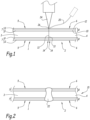
- the welding step comprises the use of a filler wire 20, as shown in dashed lines in Figure 1 .
- the laser beam 24 is additionally configured for melting the filler wire 20 at the point of impact 26 of the laser beam 24.
- the method according to the invention comprises a step of heating the thus obtained welded steel blank 15 in a heat treatment oven.
- the heating step comprises heating the welded steel blank 15 to a heat treatment temperature T t .
- a substrate is weaker than the other one if it has a lower ultimate tensile strength Ts, after press-hardening.
- the minimum temperature T min can therefore be calculated based on:
- the step of heating the welded blank 15 further includes a step of holding the welded steel blank 15 at the heat treatment temperature T t for a time comprised between 2 and 10 minutes.
- the microstructure of the weld joint 22 is not entirely austenitic.
- the fraction of intercritical ferrite in the weld joint 22 depends on the temperature difference between the heat treatment temperature T t and the full austenitization temperature Ac3(WJ) of the weld joint 22.
- the fraction of intercritical ferrite ⁇ IC in the weld joint 22 is greater than or equal to 15% and lower by at least 5% than a maximum intercritical ferrite fraction ⁇ IC max 15 % ⁇ ⁇ IC ⁇ ⁇ IC max ⁇ 5 % .
- the phases that are formed from the austenite during subsequent cooling such as martensite, transformation ferrite and/or bainite, inherit the Mn content of the austenite, while the intercritical ferrite retains its lower Mn content resulting from the partitioning. Therefore, on the Mn elemental mapping image, the intercritical ferrite can be distinguished from other phases, and in particular from other types of ferrite, and corresponds to the areas in which the Mn content is minimum.
- the microstructure of the substrates 3, 4 of the first and second precoated steel sheets 1, 2 is entirely austenitic.
- the full austenitization temperature Ac3 of the substrates 3, 4 is strictly lower than the full austenitization temperature Ac3(WJ) of the weld joint 22.
- the cooling step is carried out in the press-forming tool, for example by using a forming tool provided with a cooling system, comprising, for example, cooling channels formed in the press-forming tool.
- both substrates 3, 4 have a mainly martensitic and/or bainitic structure.
- microstructure consists of martensite and/or bainite and at most 5% of ferrite.
- each coated steel part portion comprises a steel substrate having, on at least one of its main faces, an aluminum-containing coating comprising iron and at least 30 wt.% of aluminum.
- the aluminum-containing coating of the first and second steel part portions results from the at least partial alloying of the precoating 7, 8 during the hot-press forming.
- the substrates of the first and second steel part portions have the compositions described above for the precoated steel sheets 1,2. They result from the hot press-forming and cooling of the substrates 3,4 of the precoated steel sheets 1,2.
- the substrate of the first coated steel part portion has an ultimate tensile strength Ts 1 strictly greater than the ultimate tensile strength Ts 2 of the substrate of the second coated steel part portion.
- the first coated steel part portion has a first thickness and the second coated steel part portion has a second thickness, and the product of the first thickness by the ultimate tensile strength of the first coated steel part portion is strictly greater than the product of the second thickness by the ultimate tensile strength Ts 2 of the second coated steel part portion.
- the weld joint 22 has an aluminum content comprised between 0.5 wt.% and 1.25 wt.%.
- the weld joint 22 has a microstructure comprising martensite and/or bainite and an intercritical ferrite fraction ⁇ IC greater than or equal to 15% and lower by at least 5% than a maximum intercritical ferrite fraction ⁇ IC max 15 % ⁇ ⁇ IC ⁇ ⁇ IC max ⁇ 5 % .
- the maximum intercritical ferrite fraction ⁇ IC max may be determined as explained above.
- the carbon content C FW of the filler material may then be determined based on the carbon contents of the substrates 3, 4, the proportion ⁇ of filler material determined based on the aluminum content of the weld joint 22, and the measured content of carbon in the weld joint 22.
- the ultimate tensile strength of the weld joint 22 is greater than or equal to that of the weakest substrate 4 after press-hardening.
- the steel on at least one side of the weld joint 22, corresponding to the steel of at least the first substrate 3, has a mainly martensitic and/or bainitic structure.
- the steel on either side of the weld joint 22, corresponding to the steel of the first substrate 3 and of the second substrate 4 has a mainly martensitic and/or bainitic structure.
- the inventors of the present invention have found out, surprisingly, that when the welded blank 15 is subjected to a heat treatment under the above-described conditions, the ultimate tensile strength of the weld joint 22 will be strictly greater than the ultimate tensile strength of the substrate 4 of the second precoated steel sheet 2, i.e. the substrate having the lowest ultimate tensile strength. Therefore, when subjected to a tensile test in a direction perpendicular to the weld joint 22, the part obtained after the above-described heat treatment does not fail in the weld joint 22, even though the structure of the weld joint 22 after heat treatment is not entirely martensitic or bainitic.
- the method according to the invention is particularly advantageous, since it allows obtaining satisfactory mechanical properties at reduced cost. Indeed, when welding together precoated steel sheets comprising an aluminum-containing precoating, it is no longer necessary to tailor the composition of the weld joint in such a manner that the full austenitization temperature of the weld joint is smaller than or equal to that of the substrates, for example by removing the precoating on both sides of the precoated steel sheets or by adding high amounts of austenite-forming elements into the weld using a filler material such as a filler wire. In particular, avoiding a removal of the precoating on both faces of the steel sheets reduces the total processing time.
- the total weight per unit area of the residual precoating 7, 8 on each of the precoated steel sheets 1, 2 was 100 g/m 2 .
- compositions of the substrates used for the experiments are disclosed in the Table 3 below.
- compositions of the filler wires used for the experiments are disclosed in Table 4 below.
- Table 3 Compositions of the substrates used in the experiments %C %Mn %Al %Ni %Cr %Si %Mo %Ti %B %Nb %S %P S1 0.22 1.22 0.043 0.02 0.228 0.304 - 0.050 0.003 0.003 0.001 0.015 S2 0.07 1.60 0.038 0.01 0.071 0.443 - 0.022 0.004 0.054 0.001 0.007 S3 0.07 1.57 0.022 - 0.003 0.041 - 0.081 - 0.046 0.002 0.014
- Table 4 Compositions of the filler wires used in the experiments %C %Mn %Al %Ni %Cr %Si %Mo %Ti %B W1 0.29 0.
- compositions are expressed in weight percent.
- the method according to the invention is therefore particularly advantageous, since it allow determining the optimal process parameters (including the minimum heat treatment temperature and amount of filler material to be added) in order to obtain a part having satisfactory properties while minimizing the production cost and time.
Landscapes
- Chemical & Material Sciences (AREA)
- Engineering & Computer Science (AREA)
- Mechanical Engineering (AREA)
- Physics & Mathematics (AREA)
- Materials Engineering (AREA)
- Metallurgy (AREA)
- Organic Chemistry (AREA)
- Optics & Photonics (AREA)
- Crystallography & Structural Chemistry (AREA)
- Thermal Sciences (AREA)
- Plasma & Fusion (AREA)
- Transportation (AREA)
- Combustion & Propulsion (AREA)
- Chemical Kinetics & Catalysis (AREA)
- Laser Beam Processing (AREA)
- Heat Treatment Of Articles (AREA)
- Coating With Molten Metal (AREA)
- Handcart (AREA)
Abstract
- providing a first and a second precoated sheet (1,2),
- butt welding the first and second precoated sheets (1) to obtain a blank (15),
- heating the blank (15) to a heat treatment temperature at least 10°C lower than the full austenitization temperature of the weld joint (22) and at least 15°C higher than a minimum temperature Tmin:

Ac3(WJ) is the full austenitization temperature of the weld joint (22)

where
Ts1 and Ts2 are the ultimate tensile strengths of the strongest and the weakest substrate after press-hardening
CFW is the carbon content of the filler material
β is the proportion of filler material
ρ is the ratio between the thicknesses of the weakest and the strongest substrate
and holding the blank (15) at the heat treatment temperature for a time between 2 and 10 minutes;
- press-forming the blank (15) into a part and cooling.
Description
- The present invention relates to a method for producing a press-hardened laser welded steel part and to the thus obtained press-hardened laser welded steel part.
- Steel parts of this type are used in particular in the automobile industry, and more particularly for the fabrication of crash management parts, such as anti-intrusion or shock absorption parts, structural parts or parts that contribute to the safety of motor vehicles.
- For such types of parts, the motor vehicle manufacturers prescribe that the weld joint should not constitute the weakest zone of the welded steel part.
- In order to prevent corrosion, the steel sheets used for manufacturing such welded steel parts are precoated with an aluminum-based precoating through hot dip coating in an aluminum-containing bath. If the steel sheets are welded without any prior preparation, the aluminum-based pre-coating will be diluted with the steel substrate within the molten metal during the welding operation. The aluminum tends to increase the full austenitization temperature of the molten metal, and therefore prevents the complete transformation into austenite during hot forming using conventional heat treatment temperatures. Consequently, it may no longer be possible to obtain an entirely martensitic or bainitic microstructure in the weld joint during the press-cooling occurring during the hot forming process.
- Furthermore, using higher heat treatment temperatures, which would allow a complete austenitization of the weld joint, is not possible, since it would result in an over-alloying of the coating with potential negative consequences on the adhesion of paint and/or on the spot weldability of the press-hardened part.
- Faced with this situation, when manufacturing parts from such precoated steel sheets, two types of solutions have been developed in the prior art in order to be able to obtain a fully martensitic structure in the weld joint after hot forming and quenching using conventional heat treatment temperatures.
- In particular,
EP2007545 describes a first solution which consists in removing the superficial layer of metal alloy at the weld edges of the precoated steel sheets so as to significantly decrease the total content of aluminum in the weld joint and therefore obtain a full austenitization temperature close to that of the base material of the precoated steel sheets. - Furthermore,
EP 2737971 ,US 2016/0144456 andWO 2014075824 describe a second solution which consists in welding the precoated steel sheets using a filler wire comprising austenite-stabilizing elements, such as carbon, manganese or nickel, so as to compensate for the presence of aluminum in the weld joint and to decrease the full austenitization temperature thereof, such that a fully martensitic structure may be obtained in the weld joint after hot forming and quenching using conventional heat treatment temperatures. - These methods are, however, not entirely satisfactory.
- Indeed, the first method is relatively time consuming. Furthermore, the second method may necessitate the addition of a relatively large amount of austenite-forming elements in order to be able to obtain an entirely martensitic structure in the weld joint after heat treatment. This addition increases the production cost, and further may result in issues resulting from a non-satisfactory weld joint geometry or from a non-homogeneous mix between the material from the precoated steel sheets and from the filler wire in the weld joint with the risk to have locally retained austenite.
- An object of the invention is therefore to provide a method for producing a welded steel blank from two such precoated sheets that allows obtaining, after press-hardening, a part having satisfactory crash performance properties, even for relatively high aluminum contents in the weld joint, at relatively low cost.
- For this purpose, the invention relates to a method for producing a press-hardened laser welded steel part comprising the following successive steps:
- providing a first precoated steel sheet and a second precoated steel sheet, each of the first and second precoated steel sheets comprising a steel substrate, at least one of the first and second precoated steel sheets having, on at least one of its main faces, an aluminum-containing precoating comprising at least 50% by weight of aluminum,
- the first precoated steel sheet having a first thickness and the second precoated steel sheet having a second thickness,
- the substrate of the first precoated steel sheet having, after press-hardening, an ultimate tensile strength strictly greater than the ultimate tensile strength, after press-hardening, of the substrate of the second precoated steel sheet, and
- the product of the first thickness by the ultimate tensile strength, after press-hardening, of the first precoated steel sheet being strictly greater than the product of the second thickness by the ultimate tensile strength of the second precoated steel sheet, then
- removing the aluminum-containing precoating over at least a fraction of its thickness on at least one main face at a weld edge or edge to be welded of at least one of the first and second precoated steel sheets, at least if the theoretical average aluminum content in the weld joint obtained by butt welding the first and second precoated steel sheets provided at the provision step, possibly using a filler material containing at most 0.05 wt.% of aluminum, is strictly greater than 1.25 wt.%, such that the theoretical average aluminum content in the weld joint obtained by butt welding the thus prepared first and second precoated steel sheets, possibly using a filler material containing at most 0.05 wt.% of aluminum, is comprised between 0.5 wt.% and 1.25 wt.%,
- butt welding the first precoated steel sheet and the second precoated steel sheet using laser welding so as to obtain a weld joint between the first and second precoated steel sheets thereby obtaining a welded blank, the welding step possibly including the use of a filler material,
- heating the welded blank to a heat treatment temperature, the heat treatment temperature being at least 10°C lower than the full austenitization temperature of the weld joint and at least 15°C higher than a minimum temperature Tmin, where

- Ac3(WJ) is the full austenitization temperature of the weld joint, in °C and Al is the content of aluminum in the weld joint, in wt.%
- and


- Ts1 is the ultimate tensile strength of the strongest substrate after press-hardening, in MPa
- Ts2 is the ultimate tensile strength of the weakest substrate after press-hardening, in MPa
- CFW is the carbon content of the filler material, in wt.%
- β is the proportion of filler material added to the weld pool, comprised between 0 and 1
- ρ is the ratio between the thickness of the precoated steel sheet comprising the weakest substrate and the thickness of the precoated steel sheet comprising the strongest substrate (ρ= t2/t1)
- and holding the welded blank at the heat treatment temperature for a time comprised between 2 and 10 minutes;
- press-forming the welded blank into a steel part; and
- cooling the thus formed steel part with a cooling speed greater than or equal to the critical martensitic or bainitic cooling speed of the most hardenable substrate among the substrates of the first and second precoated steel sheets so as to obtain a press-hardened welded steel part.
- According to particular embodiments of the method:
- the step of removing the aluminum-containing precoating is carried out:
- if the theoretical average aluminum content in the weld joint obtained by butt welding the first and second precoated steel sheets provided at the provision step, possibly using a filler material containing at most 0.05 wt.% of aluminum, is strictly greater than 1.25 wt.%,
- and optionally, if the theoretical average aluminum content in the weld joint obtained by butt welding the first and second precoated steel sheets provided at the provision step, possibly using a filler material containing at most 0.05 wt.% of aluminum, is comprised between 0.5 wt.% and 1.25 wt.%, and more particularly strictly greater than 0.5 wt.%,
- this step being carried out such that the theoretical average aluminum content in the weld joint obtained by butt welding the thus prepared first and second precoated steel sheets, possibly using a filler material containing at most 0.05 wt.% of aluminum, is comprised between 0.5 wt.% and 1.25 wt.%;
- at the end of the heating step, the microstructure of the substrates of the first and second precoated steel sheets is entirely austenitic;- the ratio between the ultimate tensile strength after press-hardening of the substrate of the first precoated steel sheet and the ultimate tensile strength after press-hardening of the substrate of the second precoated steel sheet is greater than or equal to 1.2;
- the carbon content of the substrate of the first precoated steel sheet is higher by at least 0.05 wt.% than the carbon content of the substrate of the second precoated steel sheet ;
- each of the first and second precoated steel sheets provided in the provision step comprises an aluminum-containing precoating comprising at least 50% by weight of aluminum on at least one of its main faces ;
- the first and second precoated steel sheets provided in the provision step comprise an aluminum-containing precoating comprising at least 50% by weight of aluminum on both of their main faces ;
- at the time of butt welding, the aluminum-containing precoating remains integral on both main faces of at least one among the first precoated steel sheet and the second precoated steel sheet, and for example each of the first and the second precoated steel sheets ;
- the method further comprises, prior to butt welding, a step of preparing the weld edge of at least one among the first and the second precoated steel sheet, which is intended to be incorporated at least partially into the weld joint, by removing the aluminum-containing precoating over at least a fraction of its thickness on at least one main face thereof, even if the theoretical average aluminum content in the weld joint obtained by butt welding the first and second precoated steel sheets provided at the provision step, possibly using a filler material containing at most 0.05 wt.% of aluminum, is comprised between 0.5 wt.% and 1.25 wt.%,
- the method further comprises, prior to butt welding, a step of preparing the weld edge of at least one among the first and the second precoated steel sheet, which is intended to be incorporated at least partially into the weld joint, by removing the aluminum-containing precoating over at least a fraction of its thickness on at least one main face thereof, even if the theoretical average aluminum content in the weld joint obtained by butt welding the first and second precoated steel sheets provided at the provision step, possibly using a filler material containing at most 0.05 wt.% of aluminum, is comprised between 0.5 wt.% and 1.25 wt.%, the removal step being carried out in such a manner that the theoretical average aluminum content in the weld joint obtained by butt welding the thus prepared first and second precoated steel sheets, possibly using a filler material containing at most 0.05 wt.% of aluminum, remains comprised between 0.5 wt.% and 1.25 wt.%;
- for at least one among the first and the second precoated steel sheets, the steel of the substrate comprises, by weight:


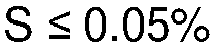


- for at least one among the first and the second precoated steel sheets, the steel of the substrate comprises, by weight:


- for at least one among the first and the second precoated steel sheets, the steel of the substrate comprises, by weight:


- for at least one among the first and the second precoated steel sheets, the steel of the substrate comprises, by weight:


- for at least one among the first and the second precoated steel sheets, the steel of the substrate comprises, by weight:



- wherein the titanium and nitrogen contents satisfy the following relationship :

- and the carbon, manganese, chromium and silicon contents satisfy the following relationship :

- the steel optionally comprising one or more of the following elements:



- the rest being iron and impurities inevitably resulting from manufacturing;
- wherein the titanium and nitrogen contents satisfy the following relationship :
- the laser welding is performed using a protection gas, in particular helium and/or argon; and
- the first and the second precoated steel sheets have different thicknesses.
- The invention further relates to a press-hardened laser welded steel part, said steel part comprising a first coated steel part portion and a second coated steel part portion,
- each coated steel part portion comprising a steel substrate, at least one among the first coated steel part portion and the second coated steel sheet having, on at least one of its main faces, an aluminum-containing coating comprising at least 30% by weight of aluminum,
- the first coated steel part portion having a first thickness and the second coated steel sheet having a second thickness, the substrate of the first coated steel part portion having an ultimate tensile strength strictly greater than the ultimate tensile strength of the substrate of the second coated steel part portion, and the product of the first thickness by the ultimate tensile strength of the first coated steel part portion being strictly greater than the product of the second thickness by the ultimate tensile strength of the second coated steel part portion;
- the first and second coated steel part portions being joined by a weld joint, said weld joint having an aluminum content comprised between 0.5 wt.% and 1.25 wt.%, and the microstructure of said weld joint comprising martensite and/or bainite and a fraction of intercritical ferrite comprised between 15% and a maximum intercritical ferrite fraction - 5%, the maximum intercritical ferrite fraction being determined using the following formula:

- Ts1 is the ultimate tensile strength of the strongest substrate after press-hardening, in MPa
- Ts2 is the ultimate tensile strength of the weakest substrate after press-hardening, in MPa
- β is the proportion of filler material added to the weld pool, comprised between 0 and 1
- CFW is the carbon content of the filler material, in wt.%
- ρ is the ratio between the thickness of the coated steel part portion comprising the weakest substrate and the thickness of the coated steel part portion comprising the strongest substrate (ρ= t2/t1)
and - the substrate of at least one among the first and the second coated steel part portions having a mainly martensitic and/or bainitic microstructure.
- According to particular embodiments of the steel part, the ratio between the ultimate tensile strength of the substrate of the first coated steel part portion and the ultimate tensile strength of the substrate of the second coated steel part portion is greater than or equal to 1.2;
- for at least one among the first and the second coated steel part portions, the steel of the substrate comprises, by weight:


- for at least one among the first and the second coated steel part portions, the steel of the substrate comprises, by weight:


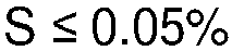


- for at least one among the first and the second coated steel part portions, the steel of the substrate comprises, by weight:





- for at least one among the first and the second coated steel part portions, the steel of the substrate comprises, by weight:









- for at least one among the first and the second coated steel part portions, the steel of the substrate comprises, by weight:


- The invention will be better understood upon reading the following specification, given only by way of example and with reference to the appended drawings, wherein:
-
Figure 1 is a schematic cross-sectional view of the beginning of the welding step of the method according to the invention, -
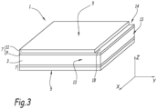
Figure 2 is a schematic cross-sectional view of a welded blank obtained at the end of the welding step, and -
Figure 3 is a perspective view of a precoated steel sheet after a preparation step. - In the entire patent application, the contents of the elements are expressed in weight percent (wt.%).
- The invention relates to a method for producing a press-hardened laser welded steel part.
- More particularly, the method comprises a first step of providing a first precoated steel sheet 1 and a second precoated steel sheet 2.
- Each precoated steel sheet 1, 2 comprises two opposite
main faces side face 13, extending between the two oppositemain faces main face Figure 3 , the precoated steel sheets 1,2 comprises four side faces 13. For example, the side faces 13 form an angle comprised between 60° and 90° with one of themain faces - As shown in
Figure 1 , each precoated steel sheet 1, 2 comprises ametallic substrate 3, 4 having, on at least one of its main faces, an aluminum-containingprecoating precoating substrate 3, 4 and in contact therewith. - The
metallic substrate 3, 4 is more particularly a steel substrate. - The steel of the
substrate 3, 4 is more particularly a steel having a ferrito-perlitic microstructure. - Preferably, the
substrate 3, 4 is made of a steel intended for thermal treatment, more particularly a press-hardenable steel, and for example a manganese-boron steel, such as a 22MnB5 type steel. - According to one embodiment, the steel of the
substrate 3, 4 comprises, by weight:





- More particularly, the steel of the
substrate 3, 4 comprises, by weight:


- According to an alternative, the steel of the
substrate 3, 4 comprises, by weight:


- According to an alternative, the steel of the
substrate 3, 4 comprises, by weight:





- According to an alternative, the steel of the
substrate 3, 4 comprises, by weight:




- The
substrate 3, 4 may be obtained, depending on its desired thickness, by hot rolling and/or by cold-rolling followed by annealing, or by any other appropriate method. - The
substrate 3, 4 advantageously has a thickness comprised between 0.6 mm and 5 mm, more particularly comprised between 0.8 mm and 5 mm, and even more particularly comprised between 1.0 mm and 2.5 mm. - According to one example, the thickness of the
substrate 3 of the first precoated steel sheet 1 is different from the thickness of the substrate 4 of the second precoated steel sheet 2. - According to an alternative, the
substrates 3, 4 of the first and second precoated steel sheets 1, 2 have the same thickness. - According to the invention, the
substrate 3 of the first precoated steel sheet 1 has, after press-hardening, an ultimate tensile strength Ts1 that is strictly greater than the ultimate tensile strength Ts2, after press-hardening, of the substrate 4 of the second precoated steel sheet 2. - In this context, "after press-hardening" means after heating to a temperature greater than or equal to the full austenitization temperature Ac3 of the considered steel substrate, hot press forming and thereafter cooling so as to obtain hardening as compared to the initial state.
- For example, the ultimate tensile strength Ts1 of the
substrate 3 of the first precoated steel sheet 1 after press-hardening is comprised between 1400 MPa and 1600 MPa or between 1700 MPa and 2000 MPa. - For example, the ultimate tensile strength Ts2 of the
substrate 3 of the second precoated steel sheet 2 after press-hardening is comprised between 500 MPa and 700 MPa or between 1000 MPa and 1200 MPa. - For example, the ratio (

substrate 3 of the first precoated steel sheet 1 after press-hardening and the ultimate tensile strength Ts2 of the substrate 4 of the second precoated steel sheet 2 after press-hardening is greater than or equal to 1.2, more particularly greater than or equal to 1.4. - Furthermore, the first precoated steel sheet 1 has a first thickness t1. The second precoated steel sheet 1 has a second thickness t2.
- The thicknesses t1, t2 are for example comprised between 0.6 mm and 5 mm, more particularly comprised between 0.8 mm and 5 mm, and even more particularly comprised between 1.0 mm and 2.5 mm.
- According to one embodiment, the thicknesses t1 and t2 are identical. According to an alternative, the thicknesses t1 and t2 are different.
- The product of the first thickness t1 by the ultimate tensile strength Ts1 of the first precoated steel sheet 1 is strictly greater than the product of the second thickness t2 by the ultimate tensile strength Ts2 of the second precoated steel sheet 1.
- In particular, the compositions of the
substrates 3 and 4 of the first and second precoated steel sheets 1, 2 are chosen among the above-described compositions. - For example, the steel of the
substrate 3 of the first precoated steel sheet 1 comprises, by weight:





- According to another example, the steel of the
substrate 3 of the first precoated steel sheet 1 comprises, by weight:





- For example, the steel of the substrate 4 of the second precoated steel sheet 2 comprises, by weight:


- According to another example, the steel of the substrate 4 of the second precoated steel sheet 2 comprises, by weight:


- Preferably, the carbon content of the
substrate 3 of the first precoated steel sheet 1 is greater by at least 0.05 wt.% than the carbon content of the substrate 4 of the second precoated steel sheet 2. - According to the invention, for at least one among the first precoated steel sheet 1 and the second precoated steel sheet 2, the aluminum-containing
precoating - Preferably, the
precoating substrate 3, 4 into a bath of molten metal. In this case, as shown inFigure 1 , theprecoating intermetallic alloy layer 9, 10 in contact with thesubstrate 3, 4. - The
intermetallic alloy layer 9, 10 comprises an intermetallic compound comprising at least iron and aluminum. Theintermetallic alloy layer 9, 10 is in particular formed by reaction between thesubstrate 3, 4 and the molten metal of the bath. More particularly, theintermetallic alloy layer 9, 10 comprises intermetallic compounds of the Fex-Aly type, and more particularly Fe2Al5. - In the example shown in
Figure 1 , theprecoating metallic alloy layer 11, 12 extending atop theintermetallic alloy layer 9, 10. Themetallic alloy layer 11, 12 has a composition which is close to that of the molten metal in the bath. It is formed by the molten metal carried away by the sheet as it travels through the molten metal bath during hot-dip coating. - The
metallic alloy layer 11, 12 is for example a layer of aluminum, a layer of aluminum alloy or a layer of aluminum-based alloy. - In this context, an aluminum alloy refers to an alloy comprising more than 50% by weight of aluminum. An aluminum-based alloy is an alloy in which aluminum is the main element, by weight.
- For example, the
metallic alloy layer 11, 12 is a layer of aluminum alloy further comprising silicon. More particularly, themetallic alloy layer 11, 12 comprises, by weight:

- The
metallic alloy layer 11, 12 has, for example, a thickness comprised between 19 µm and 33 µm or between 10 µm and 20 µm. - In the example shown in
Figure 1 , where theprecoating metallic alloy layer 11, 12, the thickness of theintermetallic alloy layer 9, 10 is generally of the order of a few micrometers. In particular, its mean thickness is typically comprised between 2 and 7 micrometers. - The particular structure of the
precoating intermetallic alloy layer 9, 10 and themetallic alloy layer 11, 12 obtained by hot-dip coating is in particular disclosed in patentEP 2 007 545 . - According to another embodiment, the aluminum-containing
precoating intermetallic alloy layer 9, 10 as described above. In this case, the thickness of theintermetallic alloy layer 9, 10 is for example comprised between 10 µm and 40 µm. Such aprecoating intermetallic alloy layer 9, 10 may for example be obtained by subjecting aprecoating intermetallic alloy layer 9, 10 and ametallic alloy layer 11, 12 as disclosed above to a pre-alloying treatment. Such a pre-alloying treatment is carried out at a temperature and for a holding time chosen so as to alloy theprecoating substrate 3, 4 over at least a fraction of the thickness of theprecoating - More particularly, the pre-alloying treatment comprises the following steps: heating the sheet to a pre-alloying temperature comprised between 620°C and 1000°C and holding the pre-alloyed sheet at this temperature for a time varying between a few minutes and several hours depending on the treatment temperature used. In this case, the
intermetallic alloy layer 9, 10 can be itself composed of different intermetallic sublayers, such as Fe2Al5, FeAl3, FeAl, Fe6Al12Si5 and FeAl3 sublayers. - Advantageously, as illustrated in
Figure 1 , thesubstrate 3, 4 is provided with an aluminum-containingprecoating - The first and second precoated steel sheets 1, 2 may carry an
identical precoating - Alternatively, the
precoatings - The theoretical average content of aluminum

- In case a filler material is intended to be used, the filler material preferably is a steel-based filler material having an aluminum content smaller than or equal to 0.05 wt.%.
- This determination is carried out in any manner known to the skilled person.
- For example, the theoretical average content of aluminum in the weld joint 22 may be determined using the following formula:

-

- Alcoating is the average aluminum content in the aluminum-containing
precoating - Mc is the weight per unit area of the aluminum-containing
precoating - β is the proportion of steel-based filler material optionally added to the weld pool, comprised between 0 and 1, where β equals zero in the case where no filler material is added to the weld pool,
- t1 is the thickness of the first precoated steel sheet 1, in mm, and
- t2 is the thickness of the second precoated steel sheet 2, in mm.
- The above formula may be used even in the case where a filler material is used, as long as the filler material comprises an aluminum content smaller than or equal to 0.05 wt.%.
- The above formula may further be used even in the case where the
substrates 3, 4 comprise aluminum, as long as the aluminum content of thesubstrates 3, 4 is smaller than or equal to 0.05 wt.%. - The proportion β of steel-based filler material optionally added to the weld pool is for example comprised between 0 and 0.5, i.e. between 0% and 50% when the proportion is expressed in percentage.
- In the case where the theoretical average content

weld edge 14 of at least one of the precoated steel sheets 1, 2 in such a manner that, after preparation, the theoretical average content of aluminum
- More particularly, the
weld edge 14 of a considered precoated steel sheet 1, 2 is the edge of the precoated steel sheet 1, 2 that is intended to be welded to the other precoated steel sheet 1, 2. - As shown more particularly in
Figure 3 , theweld edge 14 comprises a peripheral portion of the precoated steel sheet 1, 2 which is intended to be at least partially incorporated into the weld joint 22 during butt welding. More particularly, theweld edge 14 comprises aside face 13 of the precoated steel sheet 1, 2 and a portion of the precoated sheet 1,2 extending from thisside face 13 and comprising a portion of theprecoating substrate 3,4. - More particularly, the step of preparing the
weld edge 14 comprises removing the aluminum-containingprecoating main face precoating removal zone 18 extending at theweld edge 14, from theside face 13 of the precoated steel sheet 1, 2. Theremoval zone 18 may extend over a width comprised between 0.5 mm and 2 mm from theside face 13 of the precoated steel sheet 1, 2. An example of a thus prepared precoated steel sheet 1 is shown inFigure 3 . - The removal is preferably carried out using a laser beam.
- Advantageously, in the
removal zone 18, themetallic alloy layer 11, 12 is removed, while theintermetallic alloy layer 9, 10 remains over at least a fraction of its thickness. - More particularly, in the
removal zone 18, themetallic alloy layer 11, 12 is removed, while theintermetallic alloy layer 9, 10 remains intact. - The residual
intermetallic alloy layer 9, 10 protects the areas of the welded blank immediately adjacent to the weld joint 22 from oxidation and decarburization during subsequent hot-forming steps, and from corrosion during the in-use service. - In the example shown in
Figure 3 , themetallic alloy layer 11, 12 has been removed at theweld edge 14 over aremoval zone 18, leaving theintermetallic alloy layer 9, 10 intact. - In particular, the fraction of
precoating precoating 
- In particular, the
precoating - only one
main face - on two main faces in total, for example on only one
main face main faces - on three
main faces main faces main face - on four
main faces main faces - In the case where the theoretical average aluminum content

precoating precoating - Optionally, even in the case where the theoretical average aluminum content

precoating weld edge 14 on at least onemain face main face precoating weld edge 14 on only onemain face 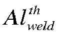
- In particular, such a removal may be carried out in order to even further decrease the heat treatment temperature Tt used for the subsequent thermal treatment, the heat treatment temperature Tt being determined as described later. Indeed, the austenitization temperature Ac3(WJ) of the weld joint 22 decreases with decreasing aluminum content. In particular, this optional removal step may be carried out in the case where the heat treatment temperature Tt determined in the absence of removal would be strictly greater than 950°C. Indeed, in order to maintain a good paintability and weldability, it is preferable to use heat treatment temperatures Tt smaller than or equal to 950°C.
- After the determination of the theoretical average aluminum content

steel blank 15. - The weld joint 22 has an aluminum content comprised between 0.5 and 1.25 wt.%.
- According to one embodiment, the welding step includes the use of a filler material.
- The filler material is advantageously a steel-based filler material having an aluminum content smaller than or equal to 0.05 wt.%. The filler material has a low content of aluminum so as to dilute the aluminum from the coating.
- For example, the filler material further comprises austenite-forming elements so as to partially balance the ferrite-forming and/or the intermetallic compound forming effect of the aluminum from the
precoating - The filler material is, for example, a filler wire or powder.
- The proportion of filler material added to the weld pool is for example comprised between 0 and 0.5.
- According to one example, the filler material has the following composition, by weight:


- According to particular examples, the filler material may have one of the compositions W1, W2 or W3 described in Table 1 below.
Table 1: Compositions of filler wires %C %Mn %Al %Ni %Cr %Si %Mo %Ti %B W1 0.29 0.85 0.03 0.1 0.15 0.15 0.025 0.035 0.004 W2 0.70 2.00 0.03 - 1.0 0.40 - 0.2 - W3 0.10 3.61 0.03 1.84 0.36 0.68 0.45 - - - In all these compositions, the contents are expressed in weight percent.
- Furthermore, for each of the compositions, the rest of the composition is iron and unavoidable impurities.
- In the above Table 1, "-" means that the composition comprises at most traces of the element.
- According to a variant, the welding step is an autogenous welding step, which means that the welding is carried out without using a filler material. In this case, the composition of the weld joint 22 depends only on the composition of the
substrates 3, 4 of the first and second precoated steel sheets 1, 2 and on the amount ofprecoating - The welding operation results in the formation of a weld joint 22 at the junction between the two sheets 1, 2.
- The welding step is a laser welding step, in which a
laser beam 24 is directed towards the junction between the two precoated steel sheets 1, 2. - The laser welding step is for example carried out using a CO2 laser or a solid state laser or a semi-conductor laser.
- The laser source is preferably a high-power laser source. It may be for example be selected from among a CO2 laser with a wavelength of 10 micrometers, a solid state laser source with a wavelength of 1 micrometer or a semi-conductor laser source, for example a diode laser with a wavelength comprised between 0.8 and 1 micrometers.
- The power of the laser is chosen depending on the thickness of the first and second precoated steel sheets 1, 2. In particular, the power is chosen so as to allow the fusion of the weld edges 14 of the precoated steel sheets 1, 2, as well as a sufficient mixing in the weld joint 22. For a CO2 laser, the laser power is for example comprised between 3 and 12 kW. For a solid state laser or a semi-conductor laser, the laser power is for example comprised between 2 and 8 kW.
- The diameter of the
laser beam 24 at the point of itsimpact 26 on the precoated steel sheets 1, 2 may be equal to about 600 µm for both types of laser sources. - During the welding step, the welding is for example carried out under a protective atmosphere. Such a protective atmosphere in particular prevents the oxidation and decarburization of the area where the weld is being performed, the formation of boron nitride in the weld joint 22 and possible cold cracking due to hydrogen absorption.
- The protective atmosphere is, for example, formed by an inert gas or a mixture of inert gases. The inert gases may be helium or argon or a mixture of these gases.
- The welding may be carried out using the laser beam as the only heat source.
- Optionally, the laser welding step includes, in addition to the laser beam, an additional heat source, such as, for example, an electric arc or an induction heating. This additional heat source contributes to melt the edges of the first and second precoated steel sheets 1, 2 in order to form the weld joint 22.
- Optionally, the welding step comprises the use of a
filler wire 20, as shown in dashed lines inFigure 1 . In this case, thelaser beam 24 is additionally configured for melting thefiller wire 20 at the point ofimpact 26 of thelaser beam 24. - During the welding step, the distance between the facing weld edges 14 of the two precoated steel sheets 1, 2 is for example smaller than or equal to 0.3 mm, and more particularly smaller than or equal to 0.1 mm. Providing such a clearance between the facing weld edges 14 of the two sheets 1, 2 promotes the deposition of the material from a
possible filler wire 20 during the welding operation and prevents the forming of an over-thickness at the weld joint 22. - At the end of the welding step, a welded
steel blank 15 as shown inFigure 2 is obtained. - After the welding step, the method according to the invention comprises a step of heating the thus obtained welded
steel blank 15 in a heat treatment oven. - More particularly, the heating step comprises heating the welded
steel blank 15 to a heat treatment temperature Tt. - According to the invention, the heat treatment temperature Tt is at least 10°C lower than the full austenitization temperature Ac3(WJ) of the weld joint 22.
- The full austenitization temperature Ac3(WJ) of the weld joint 22, in °C, is for example determined from the composition of the weld joint 22 using the following formula:
Ac3(WJ) = 102.2 × Al + 439 × C + 181.9 × Mn + 364.1 × Si + 148 × Al2 - 425.2 × C2 -29.2 × Mn2 - 497.8 × Si2- 400 × Al × C + 9.9 × Al × Mn - 50.5 × Al × Si - 208.9 × C × Mn + 570.3, where Al, C, Mn and Si refers, respectively, to the content of aluminum, carbon, manganese and silicon in the weld joint 22, in wt %. - The above formula for Ac3(WJ) may be used in the content ranges expressed in Table 2 below:
Table 2: Content ranges for Ac3 formula %Min %Max C 0.05 0.35 Mn 0.1 5 Si 0.1 0.5 Al 0.03 1.5 Cr 0.01 2 Ni - 2 Ti 0.001 0.2 Nb 0.001 0.1 Mo - 0.1 Cu 0.001 0.1 B - 0.004 N - 0.01 Ca - 0.006 W - 0.30 S - 0.05 P - 0.1 - In the above Table 2:
- all the contents are expressed in percentage by weight.
- "-" means that there is no lower limit.
- According to the invention, the heat treatment temperature Tt is further greater by at least 15°C than a minimum temperature Tmin. In this context, the minimum temperature Tmin is defined as follows:

- Ac3(WJ) is the full austenitization temperature of the weld joint 22, in °C,
- Al is the content of aluminum in the weld joint 22, in wt.%, and

- Ts1 is the ultimate tensile strength of the
strongest substrate 3 after press-hardening, in MPa - Ts2 is the ultimate tensile strength of the weakest substrate 4 after press-hardening, in MPa
- β is the proportion of filler material added to the weld pool, comprised between 0 and 1
- CFW is the carbon content of the filler material, in wt.%
- ρ is the ratio between the thickness of the precoated steel sheet 2 comprising the weakest substrate 4 and the thickness of the precoated steel sheet 1 comprising the strongest substrate 3 (ρ= t2/t1).
- Ts1 is the ultimate tensile strength of the
- In this context, a substrate is weaker than the other one if it has a lower ultimate tensile strength Ts, after press-hardening.
- The minimum temperature Tmin can therefore be calculated based on:
- the chemical composition of the weld joint 22,
- the properties of the
substrates 3,4 of the precoated steel sheets 1, 2, - in the case where a filler material is used, the proportion and composition of the filler material.
- The step of heating the welded blank 15 further includes a step of holding the welded
steel blank 15 at the heat treatment temperature Tt for a time comprised between 2 and 10 minutes. - At the end of the heating step, since the welded
steel blank 15 has been heated to a temperature which is at least 10°C lower than the full austenitization temperature Ac3(WJ) of the weld joint 22, the microstructure of the weld joint 22 is not entirely austenitic. The fraction of intercritical ferrite in the weld joint 22 depends on the temperature difference between the heat treatment temperature Tt and the full austenitization temperature Ac3(WJ) of the weld joint 22. In particular, at the end of the heating step, the fraction of intercritical ferrite αIC in the weld joint 22 is greater than or equal to 15% and lower by at least 5% than a maximum intercritical ferrite fraction
- The maximum intercritical ferrite fraction


- Ts1 is the ultimate tensile strength of the
strongest substrate 3 after press-hardening, in MPa - Ts2 is the ultimate tensile strength of the weakest substrate 4 after press-hardening, in MPa
- β is the proportion of filler material added to the weld pool, comprised between 0 and 1
- CFW is the carbon content of the filler material, in wt.%
- ρ is the ratio between the thickness of the precoated steel sheet 2 comprising the weakest substrate 4 and the thickness of the precoated steel sheet 1 comprising the strongest substrate 3 (ρ= t2/t1).
- As is known to the skilled person, the intercritical ferrite fraction can be measured for example by direct quenching of the welded blank 15 after heating to the heat treatment temperature Tt. After adapted Nital etching, the intercritical ferrite appears as a pale constituent over a greyish martensite matrix.
- The intercritical ferrite fraction in the weld joint 22 may also be determined through analysis of a manganese elemental mapping image of a sample, showing the distribution of the manganese content in the sample. Such a mapping image may for example be obtained by analysis of a sample through electron probe micro-analysis (EPMA). In this Mn mapping image, the areas exhibiting Mn content minima coincide with the intercritical ferrite areas, while the areas having a higher Mn content correspond to the phases resulting from the transformation of the austenite formed during intercritical annealing. Therefore, the surface fraction of intercritical ferrite corresponds to the surface fraction of the areas of Mn content minima in this image. This method is, for example, described in the document Hanlon, D; Rijkenberg, A; Leunis, E et al: Quantitative phase analysis of multi-phase steels, PHAST (2007), ISBN 92-79-02658-5, pages 77-79. Indeed, it is known that, during intercritical annealing, a partitioning of the manganese occurs between the austenite and the ferrite, the manganese migrating from the ferrite to the austenite such that, at the end of the intercritical annealing, the Mn content of the intercritical ferrite is strictly smaller than the Mn content of the austenite. The phases that are formed from the austenite during subsequent cooling, such as martensite, transformation ferrite and/or bainite, inherit the Mn content of the austenite, while the intercritical ferrite retains its lower Mn content resulting from the partitioning. Therefore, on the Mn elemental mapping image, the intercritical ferrite can be distinguished from other phases, and in particular from other types of ferrite, and corresponds to the areas in which the Mn content is minimum.
- In the context of this patent application, all the fractions relating to the microstructure are expressed in surface percent.
- At the end of the heating step, the microstructure of the
substrates 3, 4 of the first and second precoated steel sheets 1, 2 is entirely austenitic. In particular, due to the presence of aluminum from theprecoating substrates 3, 4 is strictly lower than the full austenitization temperature Ac3(WJ) of the weld joint 22. - At the end of the heating step, the welded
steel blank 15 is hot formed in a press into a steel part in a press-forming tool. For example, the weldedsteel blank 15 is formed into the steel part by hot stamping using an adapted hot stamping tool. - Preferably, the transfer time between the heat treatment oven and the press-forming tool is smaller than or equal to 10 seconds. It is for example comprised between 5 and 10 seconds. The transfer time is chosen to be as short as possible in order to avoid metallurgical transformations in the welded blank 15, in particular the formation of ferrite, prior to hot forming.
- The thus formed steel part is then cooled with a cooling speed greater than or equal to the critical martensitic or bainitic cooling speed of the most
hardenable substrate 3, 4 among thesubstrates 3, 4 of the first and second precoated steel sheets 1, 2. - Advantageously, the cooling step is carried out in the press-forming tool, for example by using a forming tool provided with a cooling system, comprising, for example, cooling channels formed in the press-forming tool.
- According to the invention, at the end of the cooling step, the weld joint 22 has a microstructure comprising martensite and/or bainite and an intercritical ferrite fraction αIC greater than or equal to 15% and lower by at least 5% than a maximum intercritical ferrite fraction


- At the end of the cooling step, at least one among the
substrates 3, 4 has a mainly martensitic and/or bainitic microstructure. The martensite and/or the bainite result from the transformation, during the cooling step, of the austenite formed during the heating step. - According to one example, both
substrates 3, 4 have a mainly martensitic and/or bainitic structure. - In this context, "mainly" means that the microstructure consists of martensite and/or bainite and at most 5% of ferrite.
- The present invention also relates to a press-hardened laser welded steel part obtained using the method described above.
- The part is in particular a crash management part, for example an anti-intrusion part or a shock absorbing part, a structural part or a part that contributes to the safety of a motor vehicle.
- The press-hardened laser welded steel part comprises a first coated steel part portion and a second coated steel part portion joined by a weld joint 22 as described above.
- More particularly, the first coated steel part portion and the second coated steel part portion respectively result from the hot press-forming and cooling in the press-forming tool of the first and second precoated steel sheets 1, 2.
- More particularly, each coated steel part portion comprises a steel substrate having, on at least one of its main faces, an aluminum-containing coating comprising iron and at least 30 wt.% of aluminum.
- In particular, the aluminum-containing coating of the first and second steel part portions results from the at least partial alloying of the
precoating - The substrates of the first and second steel part portions have the compositions described above for the precoated steel sheets 1,2. They result from the hot press-forming and cooling of the
substrates 3,4 of the precoated steel sheets 1,2. - The substrate of the first coated steel part portion has an ultimate tensile strength Ts1 strictly greater than the ultimate tensile strength Ts2 of the substrate of the second coated steel part portion.
- For example, the first coated steel part portion has a first thickness and the second coated steel part portion has a second thickness, and the product of the first thickness by the ultimate tensile strength of the first coated steel part portion is strictly greater than the product of the second thickness by the ultimate tensile strength Ts2 of the second coated steel part portion.
- The weld joint 22 has an aluminum content comprised between 0.5 wt.% and 1.25 wt.%.
- The weld joint 22 has a microstructure comprising martensite and/or bainite and an intercritical ferrite fraction αIC greater than or equal to 15% and lower by at least 5% than a maximum intercritical ferrite fraction

- The maximum intercritical ferrite fraction

- On the press-hardened laser welded steel part, the proportion β of filler material added to the weld pool during the welding operation may be determined by measuring the content of aluminum Alweld in the weld joint 22 through any adapted method. Knowing the content Alcoating of aluminum in the coatings of the welded steel sheets, and considering that the amount of aluminum in the filler material is negligible, the proportion β may be calculated using the formula:


substrates 3, 4, the proportion β of filler material determined based on the aluminum content of the weld joint 22, and the measured content of carbon in the weld joint 22. - The ultimate tensile strength of the weld joint 22 is greater than or equal to that of the weakest substrate 4 after press-hardening.
- The steel on at least one side of the weld joint 22, corresponding to the steel of at least the
first substrate 3, has a mainly martensitic and/or bainitic structure. For example, the steel on either side of the weld joint 22, corresponding to the steel of thefirst substrate 3 and of the second substrate 4 has a mainly martensitic and/or bainitic structure. - The inventors of the present invention have found out, surprisingly, that when the welded blank 15 is subjected to a heat treatment under the above-described conditions, the ultimate tensile strength of the weld joint 22 will be strictly greater than the ultimate tensile strength of the substrate 4 of the second precoated steel sheet 2, i.e. the substrate having the lowest ultimate tensile strength. Therefore, when subjected to a tensile test in a direction perpendicular to the weld joint 22, the part obtained after the above-described heat treatment does not fail in the weld joint 22, even though the structure of the weld joint 22 after heat treatment is not entirely martensitic or bainitic.
- Therefore, the method according to the invention is particularly advantageous, since it allows obtaining satisfactory mechanical properties at reduced cost. Indeed, when welding together precoated steel sheets comprising an aluminum-containing precoating, it is no longer necessary to tailor the composition of the weld joint in such a manner that the full austenitization temperature of the weld joint is smaller than or equal to that of the substrates, for example by removing the precoating on both sides of the precoated steel sheets or by adding high amounts of austenite-forming elements into the weld using a filler material such as a filler wire. In particular, avoiding a removal of the precoating on both faces of the steel sheets reduces the total processing time. Furthermore, reducing the amount of austenite-forming elements that have to be added through a filler material or even avoiding the use of a filler material entirely reduces the production cost, and prevents issues resulting from the addition of a high proportion of filler material, in particular relating to the geometry of the weld joint and to the obtention of a homogeneous mix between the material from the precoated steel sheets and from the filler material in the weld joint.
- The inventors of the present invention have carried out experiments E1 to E36 in which welded
steel blanks 15 were produced using precoated steel sheets 1, 2. Each precoated steel sheet 1, 2 has asubstrate 3, 4 having the composition described below (see Table 5), and, on both main faces, aprecoating precoating metal alloy layer 11, 12 comprising 88 wt.% of aluminum, 10 wt.% of silicon and 2% of iron. - The total weight per unit area of the
precoating - After removal of the
metal alloy layer 11, 12 on only one of themain faces intermetallic alloy layer 9, 10 intact, the total weight per unit area of theresidual precoating - The compositions of the substrates used for the experiments are disclosed in the Table 3 below. The compositions of the filler wires used for the experiments are disclosed in Table 4 below.
Table 3: Compositions of the substrates used in the experiments %C %Mn %Al %Ni %Cr %Si %Mo %Ti %B %Nb %S %P S1 0.22 1.22 0.043 0.02 0.228 0.304 - 0.050 0.003 0.003 0.001 0.015 S2 0.07 1.60 0.038 0.01 0.071 0.443 - 0.022 0.004 0.054 0.001 0.007 S3 0.07 1.57 0.022 - 0.003 0.041 - 0.081 - 0.046 0.002 0.014 Table 4: Compositions of the filler wires used in the experiments %C %Mn %Al %Ni %Cr %Si %Mo %Ti %B W1 0.29 0.85 0.03 0.1 0.15 0.15 0.025 0.035 0.004 W2 0.70 2.00 0.03 - 1.0 0.40 - 0.2 - W3 0.10 3.61 0.03 1.84 0.36 0.68 0.45 - - - In the above Tables 3 and 4, the compositions are expressed in weight percent.
- Furthermore, for each of the compositions in Tables 3 and 4, the rest of the composition is iron and unavoidable impurities.
- "-" means that the composition comprises at most traces of the element.
- The full austenitization temperatures Ac3 and the ultimate tensile strengths Ts of the above substrates S1, S2 and S3 are as follows:
- S1: 834°C ; Ts=1500 MPa
- S2: 858°C ; Ts=1050 MPa
- S3: 806°C ; Ts=700 MPa
- The precoated steel sheets 1, 2 were butt laser welded, using a disk laser with a power of 5.6 kW or a YAG laser with a power of 4 kW.
- In all the examples, a protective atmosphere consisting of helium or argon was used in order to avoid oxidation and decarburization of the area where the weld is being performed, as well as the formation of boron nitride in the weld joint and possible cold cracking due to hydrogen absorption. The flow rate of the gas was greater than or equal to 15 l/min.
- The welded blanks 1 were then subjected to a thermal treatment including heating to a heat treatment temperature Tt of 920°C and holding at this temperature for six minutes, transferring the blank to the hot press-forming tool with a transfer time chosen so as to prevent the formation of ferrite between the heating oven and the hot forming tool and then cooling in the press-forming tool for one minute at a cooling speed greater than or equal to 30°C/s so as to obtain a press-hardened blank.
- The experimental conditions used for experiments E1 to E36 are summarized in Tables 5 and 6 below.
- Tensile specimens were then cut from the thus obtained heat treated blanks in a direction perpendicular to the weld joint.
- Tensile testing was carried out at ambient temperature (about 20°C) using the method disclosed in the following standards: NF EN ISO 4136 and NF ISO 6892-1 on a longitudinal tensile specimen of the
type EN 12,5 x 50 (240 x 30 mm), extracted parallel to the rolling direction. For each heat treated welded blank, 5 tensile tests were carried out. - The results of the tensile testing are indicated in the column entitled "Failure location" in the Table 6 below, which indicates the location at which the failure occurred during tensile testing.
- In this column:
- "BM" refers to a failure in the base metal, i.e. in the substrate of one of the precoated sheets,
- "Weld" refers to a failure in the weld joint; and
- "Mix" refers to cases where some of the tensile specimens failed in the weld joint while others failed in the base metal.
- In the above Table 5, a precoating weight of 150 g/m2 corresponds to a case in which no preparation step has been carried out prior to welding, i.e. the precoating remains intact on both main faces of the precoated steel sheets at the time of welding, whereas a precoating weight of 100 g/m2 corresponds to a case in which the precoated steel sheets have been prepared prior to welding by removing the
metallic alloy layer 11, 12 on only one main face of each of the precoated steel sheets 1, 2, leaving theintermetallic alloy layer 9, 10 intact.Table 6: Experimental conditions (continued) and test results Experiment Tmin (°C) +15°C Tt (°C) Ac3 (WJ) (°C) - 10°C Tmin (°C)+15°C ≤ Tt (°C) ≤ Ac3(WJ) (°C) - 10°C? Failure location 
αIC (obtained at Tt) (%) + 5% αIC (obtained at Tt) + 5% ≤ 
E1 892 920 1072 Yes BM 57 50 Yes E2 853 920 1009 Yes BM 59 37 Yes E3 1022 920 1128 No Weld 32 58 No E4 954 920 1058 No Weld 37 48 No E5 899 920 995 Yes BM 42 34 Yes E6 1005 920 1119 No Weld 34 57 No E7 1107 920 1207 No Weld 26 66 No E8 956 920 1010 No Weld 26 38 No E9 924 920 1178 No Mix 61 64 No E10 838 920 987 Yes BM 61 32 Yes E11 925 920 1025 No Mix 39 41 No E12 814 920 943 Yes BM 63 18 Yes E13 892 920 946 Yes BM 32 19 Yes E14 941 920 919 No Weld 1 09 No E15 1055 920 935 No Weld 0 15 No E16 860 920 1051 Yes BM 64 46 Yes E17 958 920 1004 No Weld 23 36 No E18 876 920 920 Yes BM 30 09 Yes E19 1098 920 1181 No Weld 23 63 No E20 950 920 1019 No Mix 30 40 No E21 1034 920 1095 No Weld 23 53 No E22 916 920 971 Yes BM 29 27 Yes E23 1255 920 1375 No Weld 23 78 No E24 1032 920 1128 No Mix 29 58 No E25 1044 920 1346 No Weld 53 76 No E26 983 920 1225 No Weld 53 67 No E27 974 920 1208 No Weld 53 66 No E28 933 920 1129 No Mix 53 57 No E29 914 920 1093 Yes BM 53 53 Yes E30 890 920 1048 Yes BM 53 45 Yes E31 864 920 1000 Yes BM 53 35 Yes E32 854 920 981 Yes BM 53 30 Yes E33 1232 920 1191 No Weld 0 64 No E34 1153 920 1118 No Weld 0 56 No E35 1017 920 992 No Weld 0 33 No E36 1000 920 977 No Weld 1 28 No - In the above Tables 5 and 6, the examples which are not according to the invention are underlined.
- These results show that, when the welded blank 15 is heated to a heat treatment temperature comprised within the above-described temperature range, with a holding time comprised between 2 and 10 minutes at the heat treatment temperature, before press-forming and cooling, the failure occurs in the weakest base metal ("substrate of the second precoated steel sheet" in the above Tables 5 and 6) of the assembly, and not in the weld joint 22 (experiments E1, E2, E5, E10, E12, E13, E16, E18, E22 and E29 to E32).
- On the contrary, for a heat treatment temperature that is strictly smaller than the minimum heat treatment temperature Tmin + 15°C and for a holding time comprised between 2 and 10 minutes at the heat treatment temperature, failure is observed to either always occur in the weld joint 22 (experiments E3, E4, E6 to E8, E14, E15, E17, E19, E21, E23, E27 to E27 and E33 to E36) or to occur in the weld joint 22 in at least some of the tensile specimens for a considered experiment (experiments E9, E11, E20, E24 and E28, referenced "mix" in the table).
- The inventors have further noted that, in all the experiments that are according to the invention, the weld joint 22 has a microstructure comprising a fraction of intercritical ferrite αIC comprised between 15% and

- These results evidence that, when the welded blank 15 is heat treated using the heat treatment conditions according to the invention, the weld joint 22 has an ultimate tensile strength that is strictly greater than that of the weakest base material, corresponding to the substrate 4 of the second precoated steel sheet 2. Therefore, it is this substrate 4 that forms the weakest zone of the part, and not the weld joint 22. Failure will thus occur in the substrate 4 of the second precoated steel sheet 2 and not in the weld joint 22 itself. These results are surprising, since they are obtained even though the weld joint 22 has not been entirely austenitized and therefore does not have a mainly martensitic and/or bainitic microstructure after heat treatment.
- The method according to the invention is therefore particularly advantageous, since it allow determining the optimal process parameters (including the minimum heat treatment temperature and amount of filler material to be added) in order to obtain a part having satisfactory properties while minimizing the production cost and time.
| Experiment | Substrate of the first precoated steel sheet | Thickness t1 of the first precoated steel sheet (mm) | Substrate of the second precoated steel sheet | Thickness t2 of the second precoated steel sheet (mm) | P (t2/t1) | Ts1xt1-Ts2xt2 (mm.MPa) | Filler wire | Filler wire proportion (%) | Precoating weight per unit area at the time of butt welding (g/m2) | Calculated aluminum content in the obtained weld joint (in wt.%) |
| E1 | S1 | 1.5 | S3 | 1.5 | 1.00 | 1200 | W1 | 10 | 150 | 1.02 |
| E2 | S1 | 2.0 | S3 | 1.5 | 0.75 | 1950 | W1 | 10 | 150 | 0.87 |
| E3 | S1 | 1.2 | S3 | 1.5 | 1.25 | 750 | W1 | 10 | 150 | 1.13 |
| E4 | S1 | 1.2 | S3 | 1.5 | 1.25 | 750 | W1 | 20 | 150 | 1.00 |
| E5 | S1 | 1.2 | S3 | 1.5 | 1.25 | 750 | W1 | 30 | 150 | 0.88 |
| E6 | S1 | 1.2 | S3 | 1.5 | 1.25 | 750 | W2 | 10 | 150 | 1.13 |
| E7 | S1 | 1.2 | S3 | 1.5 | 1.25 | 750 | - | 0 | 150 | 1.25 |
| E8 | S1 | 1.2 | S3 | 1.5 | 1.25 | 750 | - | 0 | 100 | 0.84 |
| E9 | S1 | 1.0 | S3 | 1.0 | 1.00 | 800 | W1 | 25 | 150 | 1.27 |
| E10 | S1 | 1.5 | S3 | 1.5 | 1.00 | 1200 | W1 | 25 | 150 | 0.85 |
| E11 | S1 | 1.2 | S3 | 1.5 | 1.25 | 750 | W1 | 25 | 150 | 0.94 |
| E12 | S1 | 2.0 | S3 | 1.5 | 0.75 | 1950 | W1 | 25 | 150 | 0.73 |
| E13 | S1 | 1.5 | S3 | 2.0 | 1.33 | 850 | W1 | 25 | 150 | 0.73 |
| E14 | S1 | 1.5 | S3 | 2.5 | 1.67 | 500 | W1 | 25 | 150 | 0.63 |
| E15 | S1 | 1.2 | S3 | 2.5 | 2.08 | 50 | W1 | 25 | 150 | 0.69 |
| E16 | S1 | 1.5 | S3 | 1.0 | 0.67 | 1550 | W1 | 25 | 150 | 1.02 |
| E17 | S1 | 1.6 | S2 | 1.2 | 0.75 | 1140 | - | 0 | 100 | 0.81 |
| E18 | S1 | 1.6 | S2 | 1.2 | 0.75 | 1140 | W1 | 25 | 100 | 0.60 |
| E19 | S1 | 1.6 | S2 | 1.2 | 0.75 | 1140 | - | 0 | 150 | 1.21 |
| E20 | S1 | 1.6 | S2 | 1.2 | 0.75 | 1140 | W1 | 25 | 150 | 0.91 |
| E21 | S1 | 1.2 | S2 | 1.0 | 0.83 | 750 | - | 0 | 100 | 1.03 |
| E22 | S1 | 1.2 | S2 | 1.0 | 0.83 | 750 | W1 | 25 | 100 | 0.77 |
| E23 | S1 | 1.2 | S2 | 1.0 | 0.83 | 750 | - | 0 | 150 | 1.54 |
| E24 | S1 | 1.2 | S2 | 1.0 | 0.83 | 750 | W1 | 25 | 150 | 1.15 |
| E25 | S1 | 1.0 | S3 | 1.0 | 1.00 | 800 | W3 | 15 | 150 | 1.44 |
| E26 | S1 | 1.0 | S3 | 1.0 | 1.00 | 800 | W3 | 30 | 150 | 1.18 |
| E27 | S1 | 1.2 | S3 | 1.2 | 1.00 | 960 | W3 | 15 | 150 | 1.20 |
| E28 | S1 | 1.2 | S3 | 1.2 | 1.00 | 960 | W3 | 30 | 150 | 0.99 |
| E29 | S1 | 1.5 | S3 | 1.5 | 1.00 | 1200 | W3 | 15 | 150 | 0.96 |
| E30 | S1 | 1.5 | S3 | 1.5 | 1.00 | 1200 | W3 | 30 | 150 | 0.79 |
| E31 | S1 | 2.0 | S3 | 2.0 | 1.00 | 1600 | W3 | 15 | 150 | 0.72 |
| E32 | S1 | 2.0 | S3 | 2.0 | 1.00 | 1600 | W3 | 30 | 150 | 0.59 |
| E33 | S1 | 1.0 | S3 | 1.5 | 1.50 | 450 | W3 | 15 | 150 | 1.15 |
| E34 | S1 | 1.0 | S3 | 1.5 | 1.50 | 450 | W3 | 30 | 150 | 0.95 |
| E35 | S1 | 1.7 | S3 | 2.5 | 1.47 | 800 | W3 | 15 | 150 | 0.68 |
| E36 | S1 | 1.7 | S3 | 2.5 | 1.47 | 800 | W3 | 30 | 150 | 0.56 |
Claims (23)
- Method for producing a press-hardened laser welded steel part comprising the following successive steps:- providing a first precoated steel sheet (1) and a second precoated steel sheet (2), each of the first and second precoated steel sheets (1, 2) comprising a steel substrate (3, 4), at least one of the first and second precoated steel sheets (1, 2) having, on at least one of its main faces, an aluminum-containing precoating (7, 8) comprising at least 50% by weight of aluminum,the first precoated steel sheet (1) having a first thickness (t1) and the second precoated steel sheet (2) having a second thickness (t2),the substrate (3, 4) of the first precoated steel sheet (1) having, after press-hardening, an ultimate tensile strength (Ts1) strictly greater than the ultimate tensile strength (Ts2), after press-hardening, of the substrate (4) of the second precoated steel sheet (2), andthe product of the first thickness (t1) by the ultimate tensile strength (Ts1), after press-hardening, of the first precoated steel sheet (1) being strictly greater than the product of the second thickness (t2) by the ultimate tensile strength (Ts2) of the second precoated steel sheet (1), then- removing the aluminum-containing precoating (7, 8) over at least a fraction of its thickness on at least one main face (5, 6) at a weld edge (14) of at least one of the first and the second precoated steel sheets (1,2), at least if the theoretical average aluminum content (

 - butt welding the first precoated steel sheet (1) and the second precoated steel sheet (2) using laser welding so as to obtain a weld joint (22) between the first and second precoated steel sheets (1,2) thereby obtaining a welded blank (15), the welding step possibly including the use of a filler material (20),- heating the welded blank (15) to a heat treatment temperature (Tt), the heat treatment temperature (Tt) being at least 10°C lower than the full austenitization temperature (Ac3(WJ)) of the weld joint (22) and at least 15°C higher than a minimum temperature Tmin, where
 Ac3(WJ) is the full austenitization temperature of the weld joint (22), in °C and Al is the content of aluminum in the weld joint (22), in wt.%and
 Ts1 is the ultimate tensile strength of the strongest substrate (3) after press-hardening, in MPaTs2 is the ultimate tensile strength of the weakest substrate (4) after press-hardening, in MPaCFW is the carbon content of the filler material, in wt.%β is the proportion of filler material added to the weld pool, comprised between 0 and 1ρ is the ratio between the thickness of the precoated steel sheet (2) comprising the weakest substrate and the thickness of the precoated steel sheet (1) comprising the strongest substrate (ρ= t2/t1)and holding the welded blank (15) at the heat treatment temperature (Tt) for a time comprised between 2 and 10 minutes;- press-forming the welded blank (15) into a steel part; and- cooling the thus formed steel part with a cooling speed greater than or equal to the critical martensitic or bainitic cooling speed of the most hardenable substrate among the substrates (3,4) of the first and second precoated steel sheets (1, 2) so as to obtain a press-hardened welded steel part.
 - Method according to claim 1, wherein, after press-hardening, the ratio between the ultimate tensile strength (Ts1) of the substrate (3) of the first precoated steel sheet (1) and the ultimate tensile strength (Ts2) of the substrate (4) of the second precoated steel sheet (2) is greater than or equal to 1.2.
- Method according to any one of the preceding claims, wherein the carbon content of the substrate (3) of the first precoated steel sheet (1) is higher by at least 0.05 wt.% than the carbon content of the substrate (4) of the second precoated steel sheet (2).
- Method according to any one of the preceding claims, wherein each of the first and second precoated steel sheets (1, 2) provided in the provision step comprises an aluminum-containing precoating (7, 8) comprising at least 50% by weight of aluminum on at least one of its main faces (5, 6).
- Method according to any one of the preceding claims, wherein the first and second precoated steel sheets (1, 2) provided in the provision step comprise an aluminum-containing precoating (7, 8) comprising at least 50% by weight of aluminum on both of their main faces (5, 6).
- Method according to any one of the preceding claims, wherein, at the time of butt welding, the aluminum-containing precoating (7, 8) remains integral on both main faces (5, 6) of at least one among the first precoated steel sheet (1) and the second precoated steel sheet (2), and for example each of the first and the second precoated steel sheets (1, 2).
- Method according to any one of the preceding claims, further comprising, prior to butt welding, a step of preparing the weld edge (14) of at least one among the first and the second precoated steel sheet (1,2) by removing the aluminum-containing precoating (7, 8) over at least a fraction of its thickness on at least one main face (5, 6) thereof, even if the theoretical average aluminum content (

- Method according to any one of the previous claims, wherein, for at least one among the first and the second precoated steel sheets (1, 2), the steel of the substrate (3, 4) comprises, by weight:



- Method according to claim 8, wherein, for at least one among the first and the second precoated steel sheets (1, 2), the steel of the substrate (3, 4) comprises, by weight:





- Method according to any one of claims 1 to 9, wherein, for at least one among the first and the second precoated steel sheets (1, 2), the steel of the substrate (3, 4) comprises, by weight:


- Method according to any one of claims 1 to 10, wherein, for at least one among the first and the second precoated steel sheets (1, 2), the steel of the substrate (3, 4) comprises, by weight:


- Method according to any one of claims 1 to 11, wherein, for at least one among the first and the second precoated steel sheets (1, 2), the steel of the substrate (3, 4) comprises, by weight:





- Method according to any one of the preceding claims, wherein the laser welding is performed using a protection gas, in particular helium and/or argon.
- Method according to any one of the preceding claims, wherein the first and the second precoated steel sheets (1, 2) have different thicknesses.
- Method according to any one of the previous claims, wherein the welding is carried out without using a filler material.
- Method according to any one of claims 1 to 14, wherein the welding is carried out using a filler material, the filler material preferably having the following composition, by weight:





- Press-hardened laser welded steel part, said steel part comprising a first coated steel part portion and a second coated steel part portion,each coated steel part portion comprising a steel substrate, at least one among the first coated steel part portion and the second coated steel sheet having, on at least one of its main faces, an aluminum-containing coating comprising at least 30% by weight of aluminum,the first coated steel part portion having a first thickness (t1) and the second coated steel sheet having a second thickness (t2), the substrate of the first coated steel part portion having an ultimate tensile strength (Ts1) strictly greater than the ultimate tensile strength (Ts2) of the substrate (4) of the second coated steel part portion, and the product of the first thickness (t1) by the ultimate tensile strength (Ts1) of the first coated steel part portion being strictly greater than the product of the second thickness (t2) by the ultimate tensile strength (Ts2) of the second coated steel part portion;the first and second coated steel part portions being joined by a weld joint (22), said weld joint (22) having an aluminum content comprised between 0.5 wt.% and 1.25 wt.%, and the microstructure of said weld joint (22) comprising martensite and/or bainite and a fraction of intercritical ferrite (αIC ) comprised between 15% and a maximum intercritical ferrite fraction (


 Ts1 is the ultimate tensile strength of the strongest substrate (3) after press-hardening, in MPaTs2 is the ultimate tensile strength of the weakest substrate (4) after press-hardening, in MPaβ is the proportion of filler material added to the weld pool, comprised between 0 and 1CFW is the carbon content of the filler material, in wt.%ρ is the ratio between the thickness of the coated steel part portion comprising the weakest substrate and the thickness of the coated steel part portion comprising the strongest substrate (ρ= t2/t1)
andthe substrate (3, 4) of at least one among the first and the second coated steel part portions having a mainly martensitic and/or bainitic microstructure. - Press-hardened laser welded steel part according to claim 17, wherein the ratio between the ultimate tensile strength (Ts1) of the substrate of the first coated steel part portion and the ultimate tensile strength (Ts2) of the substrate of the second coated steel part portion is greater than or equal to 1.2.
- Press-hardened laser welded steel part according to any one of claims 17 or 18, wherein, for at least one among the first and the second coated steel part portions, the steel of the substrate comprises, by weight:





- Press-hardened laser welded steel part according to claim 19, wherein, for at least one among the first and the second coated steel part portions, the steel of the substrate comprises, by weight:


- Press-hardened laser welded steel part according to any one of claims 17 to 20, wherein, for at least one among the first and the second coated steel part portions, the steel of the substrate comprises, by weight:








- Press-hardened laser welded steel part according to any one of claims 17 to 21, wherein, for at least one among the first and the second coated steel part portions, the steel of the substrate comprises, by weight:










- Press-hardened laser welded steel part according to any one of claims 17 to 22, wherein, for at least one among the first and the second coated steel part portions, the steel of the substrate comprises, by weight:


Applications Claiming Priority (3)
| Application Number | Priority Date | Filing Date | Title |
|---|---|---|---|
| PCT/IB2018/051237 WO2019166852A1 (en) | 2018-02-27 | 2018-02-27 | Method for producing a press-hardened laser welded steel part and press-hardened laser welded steel part |
| EP19712842.4A EP3758886B1 (en) | 2018-02-27 | 2019-02-26 | Method for producing a press-hardened laser welded steel part and press-hardened laser welded steel part |
| PCT/IB2019/051528 WO2019166941A1 (en) | 2018-02-27 | 2019-02-26 | Method for producing a press-hardened laser welded steel part and press-hardened laser welded steel part |
Related Parent Applications (2)
| Application Number | Title | Priority Date | Filing Date |
|---|---|---|---|
| EP19712842.4A Division EP3758886B1 (en) | 2018-02-27 | 2019-02-26 | Method for producing a press-hardened laser welded steel part and press-hardened laser welded steel part |
| EP19712842.4A Division-Into EP3758886B1 (en) | 2018-02-27 | 2019-02-26 | Method for producing a press-hardened laser welded steel part and press-hardened laser welded steel part |
Publications (2)
| Publication Number | Publication Date |
|---|---|
| EP4534237A2 true EP4534237A2 (en) | 2025-04-09 |
| EP4534237A3 EP4534237A3 (en) | 2025-07-02 |
Family
ID=61837780
Family Applications (2)
| Application Number | Title | Priority Date | Filing Date |
|---|---|---|---|
| EP25156288.0A Pending EP4534237A3 (en) | 2018-02-27 | 2019-02-26 | Method for producing a press-hardened laser welded steel part and press-hardened laser welded steel part |
| EP19712842.4A Active EP3758886B1 (en) | 2018-02-27 | 2019-02-26 | Method for producing a press-hardened laser welded steel part and press-hardened laser welded steel part |
Family Applications After (1)
| Application Number | Title | Priority Date | Filing Date |
|---|---|---|---|
| EP19712842.4A Active EP3758886B1 (en) | 2018-02-27 | 2019-02-26 | Method for producing a press-hardened laser welded steel part and press-hardened laser welded steel part |
Country Status (17)
| Country | Link |
|---|---|
| US (4) | US20210362762A1 (en) |
| EP (2) | EP4534237A3 (en) |
| JP (4) | JP7191983B2 (en) |
| KR (3) | KR102650255B1 (en) |
| CN (5) | CN116117319B (en) |
| BR (1) | BR122022025885B1 (en) |
| CA (2) | CA3206436A1 (en) |
| ES (1) | ES3030700T3 (en) |
| FI (1) | FI3758886T3 (en) |
| HU (1) | HUE070989T2 (en) |
| MA (1) | MA69245B1 (en) |
| MX (2) | MX2020008911A (en) |
| PL (1) | PL3758886T3 (en) |
| RU (1) | RU2746702C1 (en) |
| UA (1) | UA130336C2 (en) |
| WO (2) | WO2019166852A1 (en) |
| ZA (1) | ZA202005048B (en) |
Families Citing this family (22)
| Publication number | Priority date | Publication date | Assignee | Title |
|---|---|---|---|---|
| CN111215751B (en) * | 2019-03-29 | 2022-06-28 | 宝山钢铁股份有限公司 | A steel differentially welded component with aluminum or aluminum alloy coating and its manufacturing method |
| WO2021130524A1 (en) * | 2019-12-24 | 2021-07-01 | Arcelormittal | Pre-coated steel sheet comprising an additional coating for increasing the mechanical strength of the weld metal zone of a welded steel part prepared from said pre-coated sheet |
| KR102273869B1 (en) * | 2020-06-02 | 2021-07-06 | 현대제철 주식회사 | Aluminum coated blank, manufacturing method thereof and manufacturing device for aluminum coated blank |
| US20230373038A1 (en) * | 2020-10-21 | 2023-11-23 | Verdicio Solutions A.I.E. | A method for the manufacture of a welded joint by Narrow Gap Welding |
| KR102308832B1 (en) * | 2020-10-29 | 2021-10-05 | 현대제철 주식회사 | Aluminum coated blank and manufacturing method thereof |
| KR102381830B1 (en) * | 2020-10-30 | 2022-04-01 | 주식회사 포스코 | Apparatus for preventing welding distortion, and method for welding pipe and flange using the same |
| CN112548395A (en) * | 2020-11-27 | 2021-03-26 | 无锡朗贤轻量化科技股份有限公司 | Welding wire for laser filler wire welding, preparation method and tailor-welded blank manufacturing process |
| CN112593153A (en) * | 2020-11-27 | 2021-04-02 | 无锡朗贤轻量化科技股份有限公司 | High-temperature-oxidation-resistant high-toughness laser tailor-welded blank and hot stamping process thereof |
| CN112455024B (en) * | 2021-02-03 | 2021-04-27 | 育材堂(苏州)材料科技有限公司 | Laser Tailored Welded Pre-Coated Steel Plate and Its Hot Stamped Components |
| KR102440343B1 (en) * | 2021-06-30 | 2022-09-05 | 현대제철 주식회사 | Aluminum coated blank and manufacturing method thereof |
| KR102785702B1 (en) * | 2021-08-05 | 2025-03-26 | 주식회사 포스코 | Tailor welded blanks, hot press formed part and manufacturing method for thereof |
| CN115961212A (en) * | 2021-10-12 | 2023-04-14 | 通用汽车环球科技运作有限责任公司 | Assembly with spliced mechanical and corrosive properties |
| WO2023095477A1 (en) * | 2021-11-29 | 2023-06-01 | Jfeスチール株式会社 | Method for producing laser/arc hybrid welded joint |
| JP7832450B2 (en) * | 2021-12-14 | 2026-03-18 | 日本製鉄株式会社 | Solid wire for welding aluminum-plated steel sheets, and method for manufacturing welded joints. |
| CN114871633B (en) * | 2022-06-02 | 2024-04-30 | 马鞍山钢铁股份有限公司 | A welding wire for laser welding of aluminum-silicon pre-plated steel plates, an aluminum-silicon pre-plated steel plate laser welding component and a production method thereof |
| CN115596170B (en) * | 2022-10-17 | 2025-12-02 | 江苏君安新材料科技有限公司 | A pre-coated prefabricated panel |
| WO2024129408A1 (en) * | 2022-12-12 | 2024-06-20 | Apex Brands, Inc. | Technology receptacle for a utility cart |
| CN116921862A (en) * | 2023-08-28 | 2023-10-24 | 中国科学院上海光学精密机械研究所 | Solder for coated hot forming steel, laser welding method and welding seam thereof |
| CN118595605B (en) * | 2024-06-27 | 2026-01-09 | 鞍钢股份有限公司 | A laser welding method for hot-rolled substrates of 1200MPa grade cold-rolled high-strength steel |
| WO2026022518A1 (en) * | 2024-07-26 | 2026-01-29 | Arcelormittal | Welding method for press hardening steels having an aluminum-based coating and associated hot stamped part |
| CN119239715A (en) * | 2024-08-15 | 2025-01-03 | 宁波宝星户外用品有限公司 | Adjustable beach trolley |
| CN118756057B (en) * | 2024-09-05 | 2025-01-07 | 张家港荣盛特钢有限公司 | Wire rod for 80 kg-level welding wire and production method thereof |
Family Cites Families (41)
| Publication number | Priority date | Publication date | Assignee | Title |
|---|---|---|---|---|
| US2520226A (en) * | 1947-11-24 | 1950-08-29 | Donald E Smith | Combined golf bag and caddie cart |
| US3782752A (en) * | 1972-04-03 | 1974-01-01 | G Gobetz | Multi-purpose cart |
| US4767128A (en) * | 1987-07-27 | 1988-08-30 | T. Entrepreneur, Inc. | Wheelbarrow construction |
| US5028060A (en) * | 1990-09-12 | 1991-07-02 | Martin David A | Utility cart |
| FR2795740B1 (en) * | 1999-07-01 | 2001-08-03 | Lorraine Laminage | CALM LOW-CARBON STEEL SHEET WITH ALUMINUM FOR PACKAGING |
| US7377538B2 (en) * | 2003-02-07 | 2008-05-27 | Myrna Lea Stuart | Shopping buddy |
| US6644493B1 (en) * | 2003-02-19 | 2003-11-11 | Sandra T. Walton | Weighted garbage can with legs |
| US20050040616A1 (en) * | 2003-08-18 | 2005-02-24 | Dar-Hsiang Cheng | Golf bag cart |
| US20060185999A1 (en) * | 2005-02-18 | 2006-08-24 | Brad Keays | Golf travel cover |
| US7243929B2 (en) * | 2005-04-21 | 2007-07-17 | Suchecki Glen R | Utility cart |
| WO2007118939A1 (en) | 2006-04-19 | 2007-10-25 | Arcelor France | Method of producing a welded part having very high mechanical properties from a rolled and coated sheet |
| FI2086755T4 (en) * | 2006-10-30 | 2026-01-23 | Arcelormittal | Coated steel strips, methods of making the same, methods of using the same, stamping blanks prepared from the same, stamped products prepared from the same, and articles of manufacture which contain such a stamped product |
| WO2008110670A1 (en) * | 2007-03-14 | 2008-09-18 | Arcelormittal France | Steel for hot working or quenching with a tool having an improved ductility |
| WO2010085983A1 (en) * | 2009-02-02 | 2010-08-05 | Arcelormittal Investigacion Y Desarrollo S.L. | Fabrication process of coated stamped parts and parts prepared from the same |
| DE102009043926A1 (en) * | 2009-09-01 | 2011-03-10 | Thyssenkrupp Steel Europe Ag | Method and device for producing a metal component |
| EP2374910A1 (en) * | 2010-04-01 | 2011-10-12 | ThyssenKrupp Steel Europe AG | Steel, flat, steel product, steel component and method for producing a steel component |
| CN102162574B (en) | 2011-03-31 | 2012-12-19 | 山东建筑大学 | Ultrahigh-strength steel laser tailor welded blank and forming process thereof |
| DE102011114555A1 (en) | 2011-09-30 | 2013-04-04 | Thyssenkrupp Tailored Blanks Gmbh | Method and apparatus for joining welding coated metal sheets |
| JP5316664B2 (en) | 2012-03-28 | 2013-10-16 | 新日鐵住金株式会社 | Tailored blank for hot stamping |
| BR112014023783B1 (en) | 2012-03-28 | 2019-09-10 | Nippon Steel & Sumitomo Metal Corp | custom-made hot stamping plate, its production method and hot stamped member |
| US9604311B2 (en) * | 2012-06-29 | 2017-03-28 | Shiloh Industries, Inc. | Welded blank assembly and method |
| US8979101B2 (en) * | 2012-10-23 | 2015-03-17 | The Coca-Cola Company | Barrel cooler with components assembleable on site |
| DE102012111118B3 (en) | 2012-11-19 | 2014-04-03 | Wisco Tailored Blanks Gmbh | Method of laser welding one or more hardenable steel workpieces in the butt joint |
| KR101448473B1 (en) | 2012-12-03 | 2014-10-10 | 현대하이스코 주식회사 | Tailor welded blnk and hot stamping parts using the same |
| DE102013101953A1 (en) * | 2013-02-27 | 2014-08-28 | Wisco Lasertechnik Gmbh | Method of joining metallic steel circuit boards or strips by laser beam welding |
| KR101318060B1 (en) * | 2013-05-09 | 2013-10-15 | 현대제철 주식회사 | Hot stamping product with advanced toughness and method of manufacturing the same |
| US10471313B2 (en) * | 2013-07-24 | 2019-11-12 | Thinh Quang Tran | Collapsible three-wheeled all-in-one golf push cart |
| DE102014001979A1 (en) * | 2014-02-17 | 2015-08-20 | Wisco Tailored Blanks Gmbh | Method of laser welding one or more hardenable steel workpieces in the butt joint |
| WO2015162445A1 (en) * | 2014-04-25 | 2015-10-29 | Arcelormittal Investigación Y Desarrollo Sl | Method and device for preparing aluminium-coated steel sheets intended for being welded and then hardened under a press; corresponding welded blank |
| ES2627220T3 (en) * | 2014-05-09 | 2017-07-27 | Gestamp Hardtech Ab | Methods for the union of two formats and the formats and products obtained |
| CN106457465B (en) | 2014-06-19 | 2018-11-09 | 麦格纳国际公司 | Method and system for carrying out laser welding to precoating sheet metal plate workpiece |
| WO2016001710A1 (en) * | 2014-07-03 | 2016-01-07 | Arcelormittal | Method for producing a high strength coated steel having improved strength and ductility and obtained sheet |
| KR101714121B1 (en) | 2014-11-21 | 2017-03-09 | 현대자동차주식회사 | Method for tailor welded blanks |
| US11388965B2 (en) * | 2015-01-20 | 2022-07-19 | Karsten Manufacturing Corporation | Rolling collapsible travel luggage |
| FR3038242B1 (en) | 2015-07-02 | 2017-06-23 | Constellium Neuf-Brisach | ALUMINUM ALLOY FOR WIRELESS LASER WELDING |
| WO2017006144A1 (en) * | 2015-07-09 | 2017-01-12 | Arcelormittal | Steel for press hardening and press hardened part manufactured from such steel |
| US9637309B2 (en) * | 2015-07-31 | 2017-05-02 | Edison Nation Medical, Llc | Waste receptacle |
| DE102015115915A1 (en) | 2015-09-21 | 2017-03-23 | Wisco Tailored Blanks Gmbh | Laser welding process for the production of a semi-finished sheet of hardenable steel with an aluminum or aluminum-silicon based coating |
| CN106363301A (en) * | 2016-10-19 | 2017-02-01 | 昆山信杰汽车部件有限公司 | Processing method for welding of high-tension aluminum silicon coating plated steel plate and splicing structure thereof |
| CN106350741B (en) * | 2016-10-24 | 2017-12-19 | 大连理工大学 | A preparation method for warm forming of high-strength steel by laser tailor welding |
| CN106392328B (en) * | 2016-11-23 | 2018-08-07 | 苏州大学 | A kind of laser assembly solder method of band Al-Si coating hot forming steel |
-
2018
- 2018-02-27 WO PCT/IB2018/051237 patent/WO2019166852A1/en not_active Ceased
- 2018-03-01 US US16/487,160 patent/US20210362762A1/en not_active Abandoned
-
2019
- 2019-02-26 ES ES19712842T patent/ES3030700T3/en active Active
- 2019-02-26 JP JP2020567655A patent/JP7191983B2/en active Active
- 2019-02-26 CN CN202310117478.1A patent/CN116117319B/en active Active
- 2019-02-26 KR KR1020237000766A patent/KR102650255B1/en active Active
- 2019-02-26 MA MA69245A patent/MA69245B1/en unknown
- 2019-02-26 UA UAA202005503A patent/UA130336C2/en unknown
- 2019-02-26 MX MX2020008911A patent/MX2020008911A/en unknown
- 2019-02-26 CN CN202310117480.9A patent/CN116100151B/en active Active
- 2019-02-26 RU RU2020128319A patent/RU2746702C1/en active
- 2019-02-26 CA CA3206436A patent/CA3206436A1/en active Pending
- 2019-02-26 HU HUE19712842A patent/HUE070989T2/en unknown
- 2019-02-26 KR KR1020217030085A patent/KR102489870B1/en active Active
- 2019-02-26 FI FIEP19712842.4T patent/FI3758886T3/en active
- 2019-02-26 CN CN201980015662.7A patent/CN111788034B/en active Active
- 2019-02-26 EP EP25156288.0A patent/EP4534237A3/en active Pending
- 2019-02-26 WO PCT/IB2019/051528 patent/WO2019166941A1/en not_active Ceased
- 2019-02-26 KR KR1020207024698A patent/KR102305989B1/en active Active
- 2019-02-26 CN CN202310117484.7A patent/CN116117320B/en active Active
- 2019-02-26 CA CA3092006A patent/CA3092006C/en active Active
- 2019-02-26 CN CN202310117476.2A patent/CN116117318B/en active Active
- 2019-02-26 EP EP19712842.4A patent/EP3758886B1/en active Active
- 2019-02-26 PL PL19712842.4T patent/PL3758886T3/en unknown
- 2019-02-26 US US16/976,392 patent/US11911847B2/en active Active
- 2019-02-26 BR BR122022025885-9A patent/BR122022025885B1/en active IP Right Grant
-
2020
- 2020-08-14 ZA ZA2020/05048A patent/ZA202005048B/en unknown
- 2020-08-26 MX MX2024011543A patent/MX2024011543A/en unknown
-
2022
- 2022-12-07 JP JP2022195384A patent/JP7543381B2/en active Active
-
2024
- 2024-01-19 US US18/417,759 patent/US12564900B2/en active Active
- 2024-08-21 JP JP2024139525A patent/JP7808649B2/en active Active
-
2026
- 2026-01-19 JP JP2026007036A patent/JP2026067925A/en active Pending
- 2026-01-26 US US19/460,285 patent/US20260151857A1/en active Pending
Also Published As
Similar Documents
| Publication | Publication Date | Title |
|---|---|---|
| US12564900B2 (en) | Method for producing a press-hardened laser welded steel part and press-hardened laser welded steel part | |
| US12269533B2 (en) | Method for producing a welded steel blank and associated welded blank | |
| EP3902651B1 (en) | Method for producing a welded steel blank and associated welded steel blank |
Legal Events
| Date | Code | Title | Description |
|---|---|---|---|
| PUAI | Public reference made under article 153(3) epc to a published international application that has entered the european phase |
Free format text: ORIGINAL CODE: 0009012 |
|
| STAA | Information on the status of an ep patent application or granted ep patent |
Free format text: STATUS: REQUEST FOR EXAMINATION WAS MADE |
|
| 17P | Request for examination filed |
Effective date: 20250206 |
|
| AC | Divisional application: reference to earlier application |
Ref document number: 3758886 Country of ref document: EP Kind code of ref document: P |
|
| AK | Designated contracting states |
Kind code of ref document: A2 Designated state(s): AL AT BE BG CH CY CZ DE DK EE ES FI FR GB GR HR HU IE IS IT LI LT LU LV MC MK MT NL NO PL PT RO RS SE SI SK SM TR |
|
| REG | Reference to a national code |
Ref country code: DE Ref legal event code: R079 Free format text: PREVIOUS MAIN CLASS: B23K0101180000 Ipc: B23K0026210000 |
|
| PUAL | Search report despatched |
Free format text: ORIGINAL CODE: 0009013 |
|
| AK | Designated contracting states |
Kind code of ref document: A3 Designated state(s): AL AT BE BG CH CY CZ DE DK EE ES FI FR GB GR HR HU IE IS IT LI LT LU LV MC MK MT NL NO PL PT RO RS SE SI SK SM TR |
|
| RIC1 | Information provided on ipc code assigned before grant |
Ipc: B23K 101/18 20060101ALN20250528BHEP Ipc: C21D 1/673 20060101ALN20250528BHEP Ipc: B23K 103/04 20060101ALN20250528BHEP Ipc: B23K 101/00 20060101ALN20250528BHEP Ipc: C21D 9/46 20060101ALI20250528BHEP Ipc: C21D 9/50 20060101ALI20250528BHEP Ipc: C21D 1/18 20060101ALI20250528BHEP Ipc: B23K 26/322 20140101ALI20250528BHEP Ipc: B23K 26/21 20140101AFI20250528BHEP |
|
| GRAP | Despatch of communication of intention to grant a patent |
Free format text: ORIGINAL CODE: EPIDOSNIGR1 |
|
| STAA | Information on the status of an ep patent application or granted ep patent |
Free format text: STATUS: GRANT OF PATENT IS INTENDED |
|
| RIC1 | Information provided on ipc code assigned before grant |
Ipc: B23K 26/21 20140101AFI20260401BHEP Ipc: B23K 26/322 20140101ALI20260401BHEP Ipc: C21D 1/18 20060101ALI20260401BHEP Ipc: C21D 9/50 20060101ALI20260401BHEP Ipc: C21D 9/46 20060101ALI20260401BHEP Ipc: B23K 101/00 20060101ALN20260401BHEP Ipc: B23K 103/04 20060101ALN20260401BHEP Ipc: C21D 1/673 20060101ALN20260401BHEP Ipc: B23K 101/18 20060101ALN20260401BHEP |
|
| INTG | Intention to grant announced |
Effective date: 20260423 |
|
| P01 | Opt-out of the competence of the unified patent court (upc) registered |
Free format text: CASE NUMBER: UPC_APP_0019872_4534237/2026 Effective date: 20260630 |