EP4534233A1 - Laser notching apparatus - Google Patents
Laser notching apparatus Download PDFInfo
- Publication number
- EP4534233A1 EP4534233A1 EP23811982.0A EP23811982A EP4534233A1 EP 4534233 A1 EP4534233 A1 EP 4534233A1 EP 23811982 A EP23811982 A EP 23811982A EP 4534233 A1 EP4534233 A1 EP 4534233A1
- Authority
- EP
- European Patent Office
- Prior art keywords
- scrap
- electrode sheet
- laser
- fixed drum
- drum
- Prior art date
- Legal status (The legal status is an assumption and is not a legal conclusion. Google has not performed a legal analysis and makes no representation as to the accuracy of the status listed.)
- Pending
Links
Images





Classifications
-
- B—PERFORMING OPERATIONS; TRANSPORTING
- B08—CLEANING
- B08B—CLEANING IN GENERAL; PREVENTION OF FOULING IN GENERAL
- B08B15/00—Preventing escape of dirt or fumes from the area where they are produced; Collecting or removing dirt or fumes from that area
- B08B15/04—Preventing escape of dirt or fumes from the area where they are produced; Collecting or removing dirt or fumes from that area from a small area, e.g. a tool
-
- B—PERFORMING OPERATIONS; TRANSPORTING
- B23—MACHINE TOOLS; METAL-WORKING NOT OTHERWISE PROVIDED FOR
- B23K—SOLDERING OR UNSOLDERING; WELDING; CLADDING OR PLATING BY SOLDERING OR WELDING; CUTTING BY APPLYING HEAT LOCALLY, e.g. FLAME CUTTING; WORKING BY LASER BEAM
- B23K26/00—Working by laser beam, e.g. welding, cutting or boring
- B23K26/36—Removing material
- B23K26/362—Laser etching
-
- B—PERFORMING OPERATIONS; TRANSPORTING
- B23—MACHINE TOOLS; METAL-WORKING NOT OTHERWISE PROVIDED FOR
- B23K—SOLDERING OR UNSOLDERING; WELDING; CLADDING OR PLATING BY SOLDERING OR WELDING; CUTTING BY APPLYING HEAT LOCALLY, e.g. FLAME CUTTING; WORKING BY LASER BEAM
- B23K26/00—Working by laser beam, e.g. welding, cutting or boring
- B23K26/08—Devices involving relative movement between laser beam and workpiece
- B23K26/0823—Devices involving rotation of the workpiece
-
- B—PERFORMING OPERATIONS; TRANSPORTING
- B23—MACHINE TOOLS; METAL-WORKING NOT OTHERWISE PROVIDED FOR
- B23K—SOLDERING OR UNSOLDERING; WELDING; CLADDING OR PLATING BY SOLDERING OR WELDING; CUTTING BY APPLYING HEAT LOCALLY, e.g. FLAME CUTTING; WORKING BY LASER BEAM
- B23K26/00—Working by laser beam, e.g. welding, cutting or boring
- B23K26/14—Working by laser beam, e.g. welding, cutting or boring using a fluid stream, e.g. a jet of gas, in conjunction with the laser beam; Nozzles therefor
- B23K26/142—Working by laser beam, e.g. welding, cutting or boring using a fluid stream, e.g. a jet of gas, in conjunction with the laser beam; Nozzles therefor for the removal of by-products
-
- B—PERFORMING OPERATIONS; TRANSPORTING
- B23—MACHINE TOOLS; METAL-WORKING NOT OTHERWISE PROVIDED FOR
- B23K—SOLDERING OR UNSOLDERING; WELDING; CLADDING OR PLATING BY SOLDERING OR WELDING; CUTTING BY APPLYING HEAT LOCALLY, e.g. FLAME CUTTING; WORKING BY LASER BEAM
- B23K26/00—Working by laser beam, e.g. welding, cutting or boring
- B23K26/16—Removal of by-products, e.g. particles or vapours produced during treatment of a workpiece
-
- B—PERFORMING OPERATIONS; TRANSPORTING
- B23—MACHINE TOOLS; METAL-WORKING NOT OTHERWISE PROVIDED FOR
- B23K—SOLDERING OR UNSOLDERING; WELDING; CLADDING OR PLATING BY SOLDERING OR WELDING; CUTTING BY APPLYING HEAT LOCALLY, e.g. FLAME CUTTING; WORKING BY LASER BEAM
- B23K26/00—Working by laser beam, e.g. welding, cutting or boring
- B23K26/36—Removing material
- B23K26/38—Removing material by boring or cutting
-
- B—PERFORMING OPERATIONS; TRANSPORTING
- B23—MACHINE TOOLS; METAL-WORKING NOT OTHERWISE PROVIDED FOR
- B23K—SOLDERING OR UNSOLDERING; WELDING; CLADDING OR PLATING BY SOLDERING OR WELDING; CUTTING BY APPLYING HEAT LOCALLY, e.g. FLAME CUTTING; WORKING BY LASER BEAM
- B23K26/00—Working by laser beam, e.g. welding, cutting or boring
- B23K26/70—Auxiliary operations or equipment
- B23K26/702—Auxiliary equipment
-
- B—PERFORMING OPERATIONS; TRANSPORTING
- B23—MACHINE TOOLS; METAL-WORKING NOT OTHERWISE PROVIDED FOR
- B23K—SOLDERING OR UNSOLDERING; WELDING; CLADDING OR PLATING BY SOLDERING OR WELDING; CUTTING BY APPLYING HEAT LOCALLY, e.g. FLAME CUTTING; WORKING BY LASER BEAM
- B23K37/00—Auxiliary devices or processes, not specially adapted for a procedure covered by only one of the other main groups of this subclass
- B23K37/04—Auxiliary devices or processes, not specially adapted for a procedure covered by only one of the other main groups of this subclass for holding or positioning work
- B23K37/0426—Fixtures for other work
- B23K37/0435—Clamps
- B23K37/0443—Jigs
-
- H—ELECTRICITY
- H01—ELECTRIC ELEMENTS
- H01M—PROCESSES OR MEANS, e.g. BATTERIES, FOR THE DIRECT CONVERSION OF CHEMICAL ENERGY INTO ELECTRICAL ENERGY
- H01M4/00—Electrodes
- H01M4/02—Electrodes composed of, or comprising, active material
- H01M4/04—Processes of manufacture in general
-
- H—ELECTRICITY
- H01—ELECTRIC ELEMENTS
- H01M—PROCESSES OR MEANS, e.g. BATTERIES, FOR THE DIRECT CONVERSION OF CHEMICAL ENERGY INTO ELECTRICAL ENERGY
- H01M50/00—Constructional details or processes of manufacture of the non-active parts of electrochemical cells other than fuel cells, e.g. hybrid cells
- H01M50/50—Current conducting connections for cells or batteries
- H01M50/531—Electrode connections inside a battery casing
- H01M50/536—Electrode connections inside a battery casing characterised by the method of fixing the leads to the electrodes, e.g. by welding
-
- B—PERFORMING OPERATIONS; TRANSPORTING
- B23—MACHINE TOOLS; METAL-WORKING NOT OTHERWISE PROVIDED FOR
- B23K—SOLDERING OR UNSOLDERING; WELDING; CLADDING OR PLATING BY SOLDERING OR WELDING; CUTTING BY APPLYING HEAT LOCALLY, e.g. FLAME CUTTING; WORKING BY LASER BEAM
- B23K2101/00—Articles made by soldering, welding or cutting
- B23K2101/36—Electric or electronic devices
- B23K2101/38—Conductors
-
- H—ELECTRICITY
- H01—ELECTRIC ELEMENTS
- H01M—PROCESSES OR MEANS, e.g. BATTERIES, FOR THE DIRECT CONVERSION OF CHEMICAL ENERGY INTO ELECTRICAL ENERGY
- H01M4/00—Electrodes
- H01M4/02—Electrodes composed of, or comprising, active material
- H01M4/13—Electrodes for accumulators with non-aqueous electrolyte, e.g. for lithium-accumulators; Processes of manufacture thereof
- H01M4/139—Processes of manufacture
-
- Y—GENERAL TAGGING OF NEW TECHNOLOGICAL DEVELOPMENTS; GENERAL TAGGING OF CROSS-SECTIONAL TECHNOLOGIES SPANNING OVER SEVERAL SECTIONS OF THE IPC; TECHNICAL SUBJECTS COVERED BY FORMER USPC CROSS-REFERENCE ART COLLECTIONS [XRACs] AND DIGESTS
- Y02—TECHNOLOGIES OR APPLICATIONS FOR MITIGATION OR ADAPTATION AGAINST CLIMATE CHANGE
- Y02E—REDUCTION OF GREENHOUSE GAS [GHG] EMISSIONS, RELATED TO ENERGY GENERATION, TRANSMISSION OR DISTRIBUTION
- Y02E60/00—Enabling technologies; Technologies with a potential or indirect contribution to GHG emissions mitigation
- Y02E60/10—Energy storage using batteries
Definitions
- втори ⁇ batteries such as nickel cadmium batteries, nickel hydrogen batteries, lithium ion batteries, and lithium ion polymer batteries.
- These secondary batteries have been applied to and used for not only small products such as digital cameras, P-DVDs, MP3Ps, cellular phones, PDAs, portable game devices, power tools, and E-bikes, but also large products requiring high power such as electric vehicles and hybrid vehicles, and power storage devices or backup-power storage devices for storing surplus generated power and new renewable energy.
- the can-type secondary batteries in particular, the cylindrical secondary batteries include jelly roll-type electrode assemblies.
- An electrode active material is applied on an electrode collector having a sheet shape to manufacture an electrode sheet, and the electrode sheet is processed into a desired shape by a notching process. Subsequently, the electrode sheet may be wound together with the separator to manufacture a jelly roll-type electrode assembly.
- the notching process may be performed by physically cutting an electrode using a press die or by emitting a laser beam onto an electrode to cut same.
- the laser beam may be disturbed by scraps cut from the electrode sheet or foreign substances, such as dust particles, generated during a cutting process.
- a laser notching apparatus is required to quickly and reliably remove the scraps and foreign substances.
- a laser notching apparatus capable of forming an electrode tab on an electrode sheet through a notching process.
- the laser notching apparatus includes: a laser unit configured to emit a laser beam onto the electrode sheet; a rotating drum configured to contact the electrode sheet to move the electrode sheet; a fixed drum positioned on one side of the rotating drum in an axial direction; and a scrap-suctioning part provided in the fixed drum and configured to suction a scrap that is cut from the electrode sheet by the laser beam.
- the laser notching apparatus may further include a mask jig which is provided in the fixed drum and faces the laser unit with the electrode sheet therebetween.
- the scrap-suctioning part may be located on a downstream side of the mask jig with respect to a direction in which the electrode sheet moves.
- the scrap-suctioning part may be located between the mask jig and a lowermost end of the fixed drum with respect to a circumferential direction of the fixed drum.
- the fixed drum and the rotating drum may be arranged coaxially with each other.
- the fixed drum may be configured to face, in a radial direction thereof, a portion of an edge of the electrode sheet in a width direction.
- the fixed drum may be provided with a mounting groove to which the scrap-suctioning part is mounted.
- the scrap-suctioning part may include a suction hole that extends in a circumferential direction of the fixed drum.
- the laser notching apparatus may further include a discharge part which is connected to the scrap-suctioning part and discharges the scrap suctioned into the scrap-suctioning part.
- the fixed drum may be provided with an extension portion which extends in an axial direction of the fixed drum and is inserted into the rotating drum.
- the rotating drum may surround the extension portion and rotate about the extension portion.
- the scrap-suctioning part is mounted to the fixed drum, and thus, the scraps may be suctioned quickly and reliably compared to the case where the scrap-suctioning part is separately located outside the fixed drum.
- the scrap-suctioning part is mounted to the fixed drum, and thus, the scrap-suctioning part may suction and remove not only the scraps but also the foreign substances, such as dust particles, generated during the notching process for the electrode sheet.
- the scrap-suctioning part may be located between the mask jig and the lowermost end of the fixed drum with respect to the circumferential direction of the fixed drum. Accordingly, the scraps may be quickly suctioned into the scrap-suctioning part before drooping downward.
- the suction hole of the scrap-suctioning part may extend in the circumferential direction of the fixed drum. Accordingly, the scraps cut from the electrode sheet moving in the circumferential direction of the fixed drum may be more reliably suctioned into the suction hole.
- FIG. 1 is a side view of a laser notching apparatus according to an embodiment of the present disclosure
- FIG. 2 is a schematic view illustrating a state in which an electrode sheet of FIG. 1 is being notched.
- the laser notching apparatus may include a drum unit 100 for moving the electrode sheet 10 and a laser unit 200 for emitting a laser beam onto the electrode sheet 10.
- the drum unit 100 and the laser unit 200 may be positioned on the sides opposite to each other with respect to the electrode sheet 10.
- the laser unit 200 may emit a laser beam L (see FIG. 3 ).
- the laser unit 200 may regulate the position to which the laser beam L is emitted, and accordingly, the electrode sheet 10 may be notched to form a preset shape.
- the configuration of the laser unit 200 is well known in the art, and thus, a detailed description thereof is omitted.
- the laser notching apparatus may notch a portion of an edge of the electrode sheet 10 in the width direction.
- the laser unit 200 may emit the laser beam onto the electrode sheet 10 and notch a portion of the edge of the electrode sheet 10.
- the portion of the edge of the electrode sheet 10 in the width direction is referred to as a notching region and then described.
- a pair of laser units 200 spaced apart from each other in the width direction of the electrode sheet 10 may be provided to notch the respective notching regions.
- the mask jig 130 and the scrap-suctioning part 140 may be provided in the drum unit 100, more specifically, in a fixed drum 120 described below (see FIG. 3 ). With respect to a direction in which the electrode sheet 10 moves, the scrap-suctioning part 140 may be located on a downstream side of the mask jig 130.
- FIG. 3 is a perspective view of a laser notching apparatus according to an embodiment of the present disclosure
- FIG. 4 is a perspective view of a drum unit illustrated in FIG. 3 .
- the drum unit 100 may include a rotating drum 110, which is in contact with the electrode sheet 10 to move the electrode sheet 10, and a fixed drum 120, which is positioned on one side of the rotating drum 110 in an axial direction.
- the rotating drum 110 may be rotated by a driving device such as a motor (not shown), and the fixed drum 120 may be fixed and not rotated. That is, the rotating drum 110 may rotate relative to the fixed drum 120.
- a driving device such as a motor (not shown)
- the fixed drum 120 may be fixed and not rotated. That is, the rotating drum 110 may rotate relative to the fixed drum 120.
- the rotating drum 110 and the fixed drum 120 may be arranged coaxially with each other.
- the axial directions of the rotating drum 110 and the fixed drum 120 may be parallel to the width direction of the electrode sheet 10.
- a height difference in the radial direction between the outer circumference of the rotating drum 110 and the outer circumference of the fixed drum 120 may be very small.
- the outer circumference of the rotating drum 110 and the outer circumference of the fixed drum 120 may be located on the same curved surface. That is, the outer diameter of the fixed drum 120 and the outer diameter of the rotating drum 110 may correspond to each other.
- corresponding to each other represents being similar or identical to each other.
- the mask jig 130 may be provided with a cutting hole 131.
- the mask jig 130 may be further provided with a foreign substance-collecting hole 132.
- the laser unit 200 may face the cutting hole 131 with the notching region of the electrode sheet 10 therebetween. Therefore, the laser beam L emitted from the laser unit 200 and cutting the notching region may pass through the cutting hole 311.
- the shape of the cutting hole 131 may be determined according to the shape of the electrode tab T.
- the foreign substance-collecting hole 132 may be located near the cutting hole 131.
- the foreign substance-collecting hole 132 may collect foreign substances, such as dust particles, generated during the notching process.
- the foreign substance-collecting hole 132 is not provided in the mask jig 130, and such as dust particles may be collected in a suction hole 141 of the scrap-suctioning part 140 which is described below.
- the scrap-suctioning part 140 may be provided in the fixed drum 120.
- the fixed drum 120 may be provided with a mounting groove 121 to which the scrap-suctioning part 140 is mounted.
- the mounting groove 121 may be formed by recessing inward or cutting out a portion of the outer circumference of the fixed drum 120.
- the mounting groove 121 may be open toward the opposite side of the fixed drum 120 from the rotating drum 110 in the axial direction.
- the mask jig 130 may be mounted, together with the scrap-suctioning part 140, to the mounting groove 121.
- the scrap-suctioning part 140 may be mounted to the mounting groove 121 while being integrally formed with the mask jig 130 or fastened to each other.
- the embodiment is not limited thereto, and a separate groove, to which the mask jig 130 is mounted, may be formed in the fixed drum 120.
- the scrap-suctioning part 140 may suction the scrap 19 (see FIG. 2 ) and continuously remove the scrap 19 from the notched electrode sheet 10.
- the scrap-suctioning part 140 is mounted to the fixed drum 120, and thus, the scrap 19 may be suctioned quickly and reliably compared to the case where the scrap-suctioning part is separated from the drum unit 100 and located outside the drum unit 100.
- the laser beam L is emitted toward the mask jig 130 and notches the notching region of the electrode sheet 10.
- the scrap 19 may be generated. Therefore, the removal of the scrap 19 has to be performed after the notching process.
- the scrap-suctioning part 140 may be located on a downstream side of the mask jig 130 with respect to a direction in which the electrode sheet 10 moves.
- the scrap-suctioning part 140 may be located between the mask jig 130 and the lowermost end of the fixed drum 120 with respect to the circumferential direction of the fixed drum 120. Accordingly, before the scrap 19 droops downward, the scrap-suctioning part 140 may quickly suction the scrap 19.
- the scrap-suctioning part 140 may be provided with a suction hole 141 for suctioning the scrap 19.
- a negative pressure may act on the suction hole 141 to suction the scrap 19.
- the suction hole 141 may suction and remove not only the scrap 19 but also foreign substances, such as dust particles, generated during the notching process for the electrode sheet 10.
- the suction hole 141 may extend in the circumferential direction of the fixed drum 120. Accordingly, the scrap 19 cut from the electrode sheet 10 moving in the circumferential direction of the fixed drum 120 may be more reliably suctioned into the suction hole 141.
- the laser notching apparatus may further include a discharge part 150 which is connected to the scrap-suctioning part 140 and discharges the scrap 19 suctioned into the scrap-suctioning part 140.
- the discharge part 150 may have a pipe shape.
- the discharge part 150 may be connected to the scrap-suctioning part 140 on the outside of the fixed drum 120 in the axial direction.
- a pair of laser units 200 may be provided as described above.
- a pair of fixed drums 120 may be provided on both sides of the rotating drum 110 in the axial direction.
- the mask jig 130 and the scrap-suctioning part 140 may be provided in each of the fixed drums 120, and the discharge part 150 may be connected to the each of the fixed drums 120.
- FIG. 5 is a cross-sectional view taken along line A-A' of FIG. 4
- FIG. 6 is a cross-sectional view taken along line B-B' of FIG. 4 .
- the rotating drum 110 may have a cavity therein.
- the fixed drum 120 may be provided with an extension portion 122 which extends in an axial direction of the fixed drum 120 and is inserted into the rotating drum 110.
- the rotating drum 110 may surround the extension portion 122 and rotate about the extension portion 122.
- the inner circumference of the rotating drum 110 and the outer circumference of the extension portion 122 may face each other.
- a bearing (not shown) may be provided between the inner circumference of the rotating drum 110 and the outer circumference of the extension portion 122.
- the fixed drum 120 and the rotating drum 110 may be easily connected to each other, and a coaxial relationship between the fixed drum 120 and the rotating drum 110 may be stably maintained.
- a certain chamber communicating with the suction hole 141 may be provided inside the scrap-suctioning part 140. Therefore, the scrap 19 may be suctioned into the chamber via the suction hole 141.
- the chamber may be a space that is defined by covering the mounting groove 121 of the fixed drum 120 with the scrap-suctioning part 140.
- the embodiment is not limited thereto, and an inner space surrounded by the scrap-suctioning part 140 may be defined as the chamber.
- the chamber may communicate with the inside of the mask jig 130. Therefore, foreign substances, such as dust particles, may be suctioned into the chamber via the foreign substance-collecting hole 132 of the mask jig 130.
- the embodiment is not limited thereto, and a separate chamber may be formed inside the mask jig 130.
- the scrap-suctioning part 140 may be provided with a connection hole 142 to which the discharge part 150 is connected.
- the connection hole 142 communicates with the chamber and may pass through toward the outside of the fixed drum 120 in the axial direction. Therefore, the scrap 19, which is suctioned into the chamber via the suction hole 141 of the scrap-suctioning part 140, may be discharged to the discharge part 150 via the connection hole 142.
- a suction device (not shown) for generating negative pressure may be connected to the discharge part 150. Therefore, the negative pressure may act on the inside of the discharge part 150, and the negative pressure may act even on the chamber and the suction hole 141 via the connection hole 142. Accordingly, scraps 19 and foreign substances, such as dust particles, generated during the notching process of the electrode sheet 10 may be quickly suctioned into the suction hole 141.
- the foreign substances and the scraps 19 suctioned into the suction hole 141 are discharged to the discharge part 150, and thus, an idle time of equipment for removing the foreign substances and the scraps 19 is reduced, thereby enhancing the efficiency of the notching process.
- FIG. 7 is a perspective view of a laser notching apparatus according to another embodiment of the present disclosure
- FIG. 8 is a cross-sectional view taken along line C-C' of FIG. 7 .
- a laser notching apparatus is the same as the above-described embodiment, except that the scrap 19 is discharged via a path 123 inside a drum unit 100' instead of the discharge part 150. Therefore, hereinafter, contents overlapping those described above are omitted, and differences therebetween are mainly described.
- An extension portion 122 of a fixed drum 120 may be provided with a discharge path 123 for guiding a scrap 19 suctioned into a scrap-suctioning part 140.
- the discharge path 123 may be provided between the outer circumference and the inner circumference of the extension portion 122.
- the extension portion 122 is fixed without rotation like the fixed drum 120. Therefore, the discharge path 123 does not shake, and the scrap 19 may be stably discharged into the discharge path 123.
- the discharge path 123 may communicate with a chamber inside the scrap-suctioning part 140. Therefore, the scrap 19, which is suctioned into the chamber via a suction hole 141 of the scrap-suctioning part 140, may be discharged to the discharge path 123.
- the discharge path 123 may extend to an end of the extension portion 122.
- the end of the extension portion 122 may be located inside the rotating drum 110 or protrude from the rotating drum 110 in the axial direction of the rotating drum 110.
- a suction device (not shown) for generating negative pressure may be connected to the discharge path 123. Therefore, the negative pressure may act on the inside of the discharge path 123, and the negative pressure may act even on the chamber and the suction hole 141. Accordingly, scraps 19 and foreign substances, such as dust particles, generated during the notching process of the electrode sheet 10 may be quickly suctioned into the suction hole 141.
- the foreign substances and the scraps 19 suctioned into the suction hole 141 are discharged to the discharge path 123, and thus, an idle time of equipment for removing the foreign substances and the scraps 19 is reduced, thereby enhancing the efficiency of the notching process.
Landscapes
- Engineering & Computer Science (AREA)
- Physics & Mathematics (AREA)
- Optics & Photonics (AREA)
- Mechanical Engineering (AREA)
- Plasma & Fusion (AREA)
- Chemical & Material Sciences (AREA)
- Chemical Kinetics & Catalysis (AREA)
- Electrochemistry (AREA)
- General Chemical & Material Sciences (AREA)
- Manufacturing & Machinery (AREA)
- Laser Beam Processing (AREA)
- Connection Of Batteries Or Terminals (AREA)
Abstract
Description
- This application claims the priority of
Korean Patent Application No.10-2022-0065686 filed on May 27, 2022 - The present invention relates to a laser notching apparatus and, more specifically, to a laser notching apparatus for forming an electrode tab on an electrode sheet through a notching process.
- In general, there are several types of secondary batteries such as nickel cadmium batteries, nickel hydrogen batteries, lithium ion batteries, and lithium ion polymer batteries. These secondary batteries have been applied to and used for not only small products such as digital cameras, P-DVDs, MP3Ps, cellular phones, PDAs, portable game devices, power tools, and E-bikes, but also large products requiring high power such as electric vehicles and hybrid vehicles, and power storage devices or backup-power storage devices for storing surplus generated power and new renewable energy.
- The secondary batteries are classified into pouch-type batteries, can-type batteries, and the like according to the material of a case that accommodates an electrode assembly. In particular, the can-type batteries are manufactured by accommodating electrode assemblies in hard cans, and secondary batteries having cylindrical cans may be referred to as cylindrical secondary batteries.
- Generally, the can-type secondary batteries, in particular, the cylindrical secondary batteries include jelly roll-type electrode assemblies. An electrode active material is applied on an electrode collector having a sheet shape to manufacture an electrode sheet, and the electrode sheet is processed into a desired shape by a notching process. Subsequently, the electrode sheet may be wound together with the separator to manufacture a jelly roll-type electrode assembly. Here, the notching process may be performed by physically cutting an electrode using a press die or by emitting a laser beam onto an electrode to cut same.
- In particular, for the notching process by means of the laser beam, the laser beam may be disturbed by scraps cut from the electrode sheet or foreign substances, such as dust particles, generated during a cutting process. In order to prevent the above concern, a laser notching apparatus is required to quickly and reliably remove the scraps and foreign substances.
- An aspect of the present invention provides a laser notching apparatus capable of quickly and reliably removing the scraps and foreign substances.
- According to an aspect of the present invention, there is provided a laser notching apparatus capable of forming an electrode tab on an electrode sheet through a notching process. The laser notching apparatus includes: a laser unit configured to emit a laser beam onto the electrode sheet; a rotating drum configured to contact the electrode sheet to move the electrode sheet; a fixed drum positioned on one side of the rotating drum in an axial direction; and a scrap-suctioning part provided in the fixed drum and configured to suction a scrap that is cut from the electrode sheet by the laser beam.
- The laser notching apparatus may further include a mask jig which is provided in the fixed drum and faces the laser unit with the electrode sheet therebetween. The scrap-suctioning part may be located on a downstream side of the mask jig with respect to a direction in which the electrode sheet moves.
- The scrap-suctioning part may be located between the mask jig and a lowermost end of the fixed drum with respect to a circumferential direction of the fixed drum.
- The fixed drum and the rotating drum may be arranged coaxially with each other.
- An outer diameter of the fixed drum may correspond to an outer diameter of the rotating drum.
- The fixed drum may be configured to face, in a radial direction thereof, a portion of an edge of the electrode sheet in a width direction.
- The fixed drum may be provided with a mounting groove to which the scrap-suctioning part is mounted.
- The scrap-suctioning part may include a suction hole that extends in a circumferential direction of the fixed drum.
- The laser notching apparatus may further include a discharge part which is connected to the scrap-suctioning part and discharges the scrap suctioned into the scrap-suctioning part.
- The fixed drum may be provided with an extension portion which extends in an axial direction of the fixed drum and is inserted into the rotating drum.
- The rotating drum may surround the extension portion and rotate about the extension portion.
- The extension portion may be provided with a discharge path which guides the scrap suctioned into the scrap-suctioning part.
- According to the embodiment of the present disclosure, the scrap-suctioning part is mounted to the fixed drum, and thus, the scraps may be suctioned quickly and reliably compared to the case where the scrap-suctioning part is separately located outside the fixed drum.
- Also, the scrap-suctioning part is mounted to the fixed drum, and thus, the scrap-suctioning part may suction and remove not only the scraps but also the foreign substances, such as dust particles, generated during the notching process for the electrode sheet.
- In addition, the scrap-suctioning part may be located between the mask jig and the lowermost end of the fixed drum with respect to the circumferential direction of the fixed drum. Accordingly, the scraps may be quickly suctioned into the scrap-suctioning part before drooping downward.
- Also, the suction hole of the scrap-suctioning part may extend in the circumferential direction of the fixed drum. Accordingly, the scraps cut from the electrode sheet moving in the circumferential direction of the fixed drum may be more reliably suctioned into the suction hole.
- In addition to the effects described above, effects that can be easily predicted by those skilled in the art from the configurations according to the embodiments of the present disclosure may be included.
- The accompanying drawings illustrate an embodiment of the present disclosure, and together with the detailed description of the present disclosure described below, serve to provide further understanding of the technical ideas of the present disclosure, and thus, the present disclosure should not be construed as being limited to the drawings.
-
FIG. 1 is a side view of a laser notching apparatus according to an embodiment of the present disclosure. -
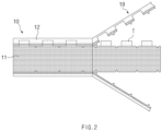
FIG. 2 is a schematic view illustrating a state in which an electrode sheet ofFIG. 1 is being notched. -
FIG. 3 is a perspective view of a laser notching apparatus according to an embodiment of the present disclosure. -
FIG. 4 is a perspective view of a drum unit illustrated inFIG. 3 . -
FIG. 5 is a cross-sectional view taken along line A-A' ofFIG. 4 . -
FIG. 6 is a cross-sectional view taken along line B-B' ofFIG. 4 . -
FIG. 7 is a perspective view of a laser notching apparatus according to another embodiment of the present disclosure. -
FIG. 8 is a cross-sectional view taken along line C-C' ofFIG. 7 . - Hereinafter, embodiments of the present invention will be described in detail with reference to the accompanying drawings so as to be easily carried out by a person skilled in the art to which the present invention pertains. However, the present invention may be embodied in various different forms, and is neither limited nor restricted to the following embodiments.
- In order to clearly describe the present invention, detailed description of parts irrelevant to the invention or detailed descriptions of related well-known technologies that may unnecessarily obscure subject matters of the invention will be omitted. In the specification, when reference numerals are given to components in each of the drawings, the same or similar components will be designated by the same or similar reference numerals throughout the specification.
- Also, terms or words used in the description and claims should not be restrictively interpreted as ordinary meanings or dictionary-based meanings, but should be interpreted as meanings and concepts conforming to the technical ideas of the present invention on the basis of the principle that an inventor can properly define the concept of a term so as to describe his or her invention in the best ways.
-
FIG. 1 is a side view of a laser notching apparatus according to an embodiment of the present disclosure, andFIG. 2 is a schematic view illustrating a state in which an electrode sheet ofFIG. 1 is being notched. - The laser notching apparatus according to an embodiment of the present disclosure may form an electrode tab T on an
electrode sheet 10 through a notching process. - The laser notching apparatus may include a
drum unit 100 for moving theelectrode sheet 10 and alaser unit 200 for emitting a laser beam onto theelectrode sheet 10. Thedrum unit 100 and thelaser unit 200 may be positioned on the sides opposite to each other with respect to theelectrode sheet 10. - The
laser unit 200 may emit a laser beam L (seeFIG. 3 ). Thelaser unit 200 may regulate the position to which the laser beam L is emitted, and accordingly, theelectrode sheet 10 may be notched to form a preset shape. The configuration of thelaser unit 200 is well known in the art, and thus, a detailed description thereof is omitted. - Referring to
FIG. 2 , theelectrode sheet 10 may include a coatedportion 11, in which an active material is applied on an electrode collector, and anuncoated portion 12, in which an active material is not applied on an electrode collector to expose the electrode collector. Theuncoated portions 12 may be positioned on both sides of the coatedportion 11 in the width direction. However, theuncoated portion 12 may be positioned on only one side of the coatedportion 11 in the width direction. - The laser notching apparatus may notch a portion of an edge of the
electrode sheet 10 in the width direction. In more detail, thelaser unit 200 may emit the laser beam onto theelectrode sheet 10 and notch a portion of the edge of theelectrode sheet 10. Hereinafter, the portion of the edge of theelectrode sheet 10 in the width direction is referred to as a notching region and then described. - When notching regions of the
electrode sheet 10 are provided on both sides of theelectrode sheet 10 in the width direction, a pair oflaser units 200 spaced apart from each other in the width direction of theelectrode sheet 10 may be provided to notch the respective notching regions. - The notching region of the
electrode sheet 10 may include theuncoated portion 12. Therefore, theuncoated portion 12 provided on one side of theelectrode sheet 10 in the width direction may be processed into the electrode tab T. Theuncoated portion 12 provided on the other side of theelectrode sheet 10 in the width direction may be notched and removed by the laser notching apparatus, but the embodiment is not limited thereto. - When the notching region of the
electrode sheet 10 is notched, ascrap 19 cut from theelectrode sheet 10 may be formed. Thescrap 19 may be continuously formed and extended. The laser notching apparatus may include a scrap-suctioningpart 140 for suctioning thescrap 19. The laser notching apparatus may further include amask jig 130 that faces thelaser unit 200 with theelectrode sheet 10 therebetween. - The
mask jig 130 and the scrap-suctioningpart 140 may be provided in thedrum unit 100, more specifically, in a fixeddrum 120 described below (seeFIG. 3 ). With respect to a direction in which theelectrode sheet 10 moves, the scrap-suctioningpart 140 may be located on a downstream side of themask jig 130. -
FIG. 3 is a perspective view of a laser notching apparatus according to an embodiment of the present disclosure, andFIG. 4 is a perspective view of a drum unit illustrated inFIG. 3 . - The
drum unit 100 may include arotating drum 110, which is in contact with theelectrode sheet 10 to move theelectrode sheet 10, and afixed drum 120, which is positioned on one side of therotating drum 110 in an axial direction. - The
rotating drum 110 may be rotated by a driving device such as a motor (not shown), and the fixeddrum 120 may be fixed and not rotated. That is, therotating drum 110 may rotate relative to the fixeddrum 120. - The
rotating drum 110 and the fixeddrum 120 may be arranged coaxially with each other. The axial directions of therotating drum 110 and the fixeddrum 120 may be parallel to the width direction of theelectrode sheet 10. - A height difference in the radial direction between the outer circumference of the
rotating drum 110 and the outer circumference of the fixeddrum 120 may be very small. Preferably, the outer circumference of therotating drum 110 and the outer circumference of the fixeddrum 120 may be located on the same curved surface. That is, the outer diameter of the fixeddrum 120 and the outer diameter of therotating drum 110 may correspond to each other. Here, corresponding to each other represents being similar or identical to each other. - A portion of the
electrode sheet 10 may face therotating drum 110, and another portion thereof may face the fixeddrum 120. In more detail, the fixeddrum 120 may face the notching region of theelectrode sheet 10 in the radial direction thereof. The notching region may include anuncoated portion 12 that is processed into an electrode tab T. - The
mask jig 130 may be provided in the fixeddrum 120. Themask jig 130 may face the notching region of theelectrode sheet 10. Thelaser unit 200 may face themask jig 130 with the notching region of theelectrode sheet 10 therebetween. Themask jig 130 may be in close contact with the notching region of theelectrode sheet 10. Accordingly, it is possible to prevent unnecessary movement of the electrode sheet S during the notching process. - The
mask jig 130 may be provided with acutting hole 131. Themask jig 130 may be further provided with a foreign substance-collectinghole 132. - The
laser unit 200 may face thecutting hole 131 with the notching region of theelectrode sheet 10 therebetween. Therefore, the laser beam L emitted from thelaser unit 200 and cutting the notching region may pass through the cutting hole 311. In order to form the electrode tab T by notching the notching region of the movingelectrode sheet 10 into a preset shape, the shape of thecutting hole 131 may be determined according to the shape of the electrode tab T. - The foreign substance-collecting
hole 132 may be located near the cuttinghole 131. The foreign substance-collectinghole 132 may collect foreign substances, such as dust particles, generated during the notching process. - Instead, foreign substances, the foreign substance-collecting
hole 132 is not provided in themask jig 130, and such as dust particles may be collected in asuction hole 141 of the scrap-suctioningpart 140 which is described below. - The scrap-suctioning
part 140 may be provided in the fixeddrum 120. In more detail, the fixeddrum 120 may be provided with a mountinggroove 121 to which the scrap-suctioningpart 140 is mounted. - The mounting
groove 121 may be formed by recessing inward or cutting out a portion of the outer circumference of the fixeddrum 120. In addition, the mountinggroove 121 may be open toward the opposite side of the fixeddrum 120 from therotating drum 110 in the axial direction. - The
mask jig 130 may be mounted, together with the scrap-suctioningpart 140, to the mountinggroove 121. For example, the scrap-suctioningpart 140 may be mounted to the mountinggroove 121 while being integrally formed with themask jig 130 or fastened to each other. However, the embodiment is not limited thereto, and a separate groove, to which themask jig 130 is mounted, may be formed in the fixeddrum 120. - The scrap-suctioning
part 140 may suction the scrap 19 (seeFIG. 2 ) and continuously remove thescrap 19 from the notchedelectrode sheet 10. - The scrap-suctioning
part 140 is mounted to the fixeddrum 120, and thus, thescrap 19 may be suctioned quickly and reliably compared to the case where the scrap-suctioning part is separated from thedrum unit 100 and located outside thedrum unit 100. - The laser beam L is emitted toward the
mask jig 130 and notches the notching region of theelectrode sheet 10. During this process, thescrap 19 may be generated. Therefore, the removal of thescrap 19 has to be performed after the notching process. For this, the scrap-suctioningpart 140 may be located on a downstream side of themask jig 130 with respect to a direction in which theelectrode sheet 10 moves. - The scrap-suctioning
part 140 may be located between themask jig 130 and the lowermost end of the fixeddrum 120 with respect to the circumferential direction of the fixeddrum 120. Accordingly, before thescrap 19 droops downward, the scrap-suctioningpart 140 may quickly suction thescrap 19. - The scrap-suctioning
part 140 may be provided with asuction hole 141 for suctioning thescrap 19. A negative pressure may act on thesuction hole 141 to suction thescrap 19. Thesuction hole 141 may suction and remove not only thescrap 19 but also foreign substances, such as dust particles, generated during the notching process for theelectrode sheet 10. - The
suction hole 141 may extend in the circumferential direction of the fixeddrum 120. Accordingly, thescrap 19 cut from theelectrode sheet 10 moving in the circumferential direction of the fixeddrum 120 may be more reliably suctioned into thesuction hole 141. - Also, the laser notching apparatus may further include a
discharge part 150 which is connected to the scrap-suctioningpart 140 and discharges thescrap 19 suctioned into the scrap-suctioningpart 140. - The
discharge part 150 may have a pipe shape. Thedischarge part 150 may be connected to the scrap-suctioningpart 140 on the outside of the fixeddrum 120 in the axial direction. - Here, when edges on both sides of the
electrode sheet 10 in the width direction are notched, a pair oflaser units 200 may be provided as described above. In this case, a pair of fixeddrums 120 may be provided on both sides of therotating drum 110 in the axial direction. Themask jig 130 and the scrap-suctioningpart 140 may be provided in each of the fixeddrums 120, and thedischarge part 150 may be connected to the each of the fixed drums 120. -
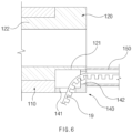
FIG. 5 is a cross-sectional view taken along line A-A' ofFIG. 4 , andFIG. 6 is a cross-sectional view taken along line B-B' ofFIG. 4 . - The
rotating drum 110 may have a cavity therein. Also, the fixeddrum 120 may be provided with anextension portion 122 which extends in an axial direction of the fixeddrum 120 and is inserted into therotating drum 110. - The
rotating drum 110 may surround theextension portion 122 and rotate about theextension portion 122. The inner circumference of therotating drum 110 and the outer circumference of theextension portion 122 may face each other. For smooth rotation of therotating drum 110, a bearing (not shown) may be provided between the inner circumference of therotating drum 110 and the outer circumference of theextension portion 122. - Therefore, the fixed
drum 120 and therotating drum 110 may be easily connected to each other, and a coaxial relationship between thefixed drum 120 and therotating drum 110 may be stably maintained. - Each of the fixed
drum 120 and theextension portion 122 may have a cavity therein. Although not illustrated inFIGS. 5 and6 , a rotating shaft that rotates together with therotating drum 110 may be located in the inner cavities of the fixeddrum 120 and theextension portion 122. - Here, a certain chamber communicating with the
suction hole 141 may be provided inside the scrap-suctioningpart 140. Therefore, thescrap 19 may be suctioned into the chamber via thesuction hole 141. - The chamber may be a space that is defined by covering the mounting
groove 121 of the fixeddrum 120 with the scrap-suctioningpart 140. However, the embodiment is not limited thereto, and an inner space surrounded by the scrap-suctioningpart 140 may be defined as the chamber. - Also, the chamber may communicate with the inside of the
mask jig 130. Therefore, foreign substances, such as dust particles, may be suctioned into the chamber via the foreign substance-collectinghole 132 of themask jig 130. However, the embodiment is not limited thereto, and a separate chamber may be formed inside themask jig 130. - The scrap-suctioning
part 140 may be provided with aconnection hole 142 to which thedischarge part 150 is connected. Theconnection hole 142 communicates with the chamber and may pass through toward the outside of the fixeddrum 120 in the axial direction. Therefore, thescrap 19, which is suctioned into the chamber via thesuction hole 141 of the scrap-suctioningpart 140, may be discharged to thedischarge part 150 via theconnection hole 142. - A suction device (not shown) for generating negative pressure may be connected to the
discharge part 150. Therefore, the negative pressure may act on the inside of thedischarge part 150, and the negative pressure may act even on the chamber and thesuction hole 141 via theconnection hole 142. Accordingly, scraps 19 and foreign substances, such as dust particles, generated during the notching process of theelectrode sheet 10 may be quickly suctioned into thesuction hole 141. - In addition, the foreign substances and the
scraps 19 suctioned into thesuction hole 141 are discharged to thedischarge part 150, and thus, an idle time of equipment for removing the foreign substances and thescraps 19 is reduced, thereby enhancing the efficiency of the notching process. -
FIG. 7 is a perspective view of a laser notching apparatus according to another embodiment of the present disclosure, andFIG. 8 is a cross-sectional view taken along line C-C' ofFIG. 7 . - A laser notching apparatus according to another embodiment of the present disclosure is the same as the above-described embodiment, except that the
scrap 19 is discharged via apath 123 inside a drum unit 100' instead of thedischarge part 150. Therefore, hereinafter, contents overlapping those described above are omitted, and differences therebetween are mainly described. - An
extension portion 122 of a fixeddrum 120 according to another embodiment of the present disclosure may be provided with adischarge path 123 for guiding ascrap 19 suctioned into a scrap-suctioningpart 140. - The
discharge path 123 may be provided between the outer circumference and the inner circumference of theextension portion 122. Theextension portion 122 is fixed without rotation like the fixeddrum 120. Therefore, thedischarge path 123 does not shake, and thescrap 19 may be stably discharged into thedischarge path 123. - The
discharge path 123 may communicate with a chamber inside the scrap-suctioningpart 140. Therefore, thescrap 19, which is suctioned into the chamber via asuction hole 141 of the scrap-suctioningpart 140, may be discharged to thedischarge path 123. - The
discharge path 123 may extend to an end of theextension portion 122. The end of theextension portion 122 may be located inside therotating drum 110 or protrude from therotating drum 110 in the axial direction of therotating drum 110. - A suction device (not shown) for generating negative pressure may be connected to the
discharge path 123. Therefore, the negative pressure may act on the inside of thedischarge path 123, and the negative pressure may act even on the chamber and thesuction hole 141. Accordingly, scraps 19 and foreign substances, such as dust particles, generated during the notching process of theelectrode sheet 10 may be quickly suctioned into thesuction hole 141. - In addition, the foreign substances and the
scraps 19 suctioned into thesuction hole 141 are discharged to thedischarge path 123, and thus, an idle time of equipment for removing the foreign substances and thescraps 19 is reduced, thereby enhancing the efficiency of the notching process. - In this embodiment, there is no need to connect a
separate discharge part 150 to the fixeddrum 120, and thus, a space required for installation of thedischarge part 150 may be reduced. - The technical ideas of the present disclosure have been described merely for illustrative purposes, and those skilled in the art will appreciate that various changes and modifications are possible without departing from the essential features of the present disclosure.
- Thus, the embodiments of the present disclosure are to be considered illustrative and not restrictive, and the technical idea of the present disclosure is not limited to the foregoing embodiments.
- The protective scope of the present disclosure is defined by the appended claims, and all technical ideas within their equivalents should be interpreted as being included in the scope of the present disclosure.
[Description of the Symbols] 10: electrode sheet 11: coated portion 12: uncoated portion 19: scrap T: electrode tab 100: drum unit 110: rotating drum 120: fixed drum 121: mounting groove 122: extension portion 123: discharge path 130: mask jig 131: cutting hole 132: foreign substance-collecting hole 140: scrap-suctioning part 141: suction hole 142: connection hole 150: discharge part 200: laser unit
Claims (12)
- A laser notching apparatus for forming an electrode tab on an electrode sheet through a notching process, the laser notching apparatus comprising:a laser unit configured to emit a laser beam onto the electrode sheet;a rotating drum configured to contact the electrode sheet to move the electrode sheet;a fixed drum positioned on one side of the rotating drum in an axial direction; anda scrap-suctioning part provided in the fixed drum and configured to suction a scrap that is cut from the electrode sheet by the laser beam.
- The laser notching apparatus of claim 1, further comprising a mask jig which is provided in the fixed drum and faces the laser unit with the electrode sheet therebetween,
wherein the scrap-suctioning part is located on a downstream side of the mask jig with respect to a direction in which the electrode sheet moves. - The laser notching apparatus of claim 2, wherein the scrap-suctioning part is located between the mask jig and a lowermost end of the fixed drum with respect to a circumferential direction of the fixed drum.
- The laser notching apparatus of claim 1, wherein the fixed drum and the rotating drum are arranged coaxially with each other.
- The laser notching apparatus of claim 4, wherein an outer diameter of the fixed drum corresponds to an outer diameter of the rotating drum.
- The laser notching apparatus of claim 1, wherein the fixed drum is configured to face, in a radial direction thereof, a portion of an edge of the electrode sheet in a width direction.
- The laser notching apparatus of claim 1, wherein the fixed drum is provided with a mounting groove to which the scrap-suctioning part is mounted.
- The laser notching apparatus of claim 1, wherein the scrap-suctioning part comprises a suction hole that extends in a circumferential direction of the fixed drum.
- The laser notching apparatus of claim 1, further comprising a discharge part which is connected to the scrap-suctioning part and discharges the scrap suctioned into the scrap-suctioning part.
- The laser notching apparatus of claim 1, wherein the fixed drum is provided with an extension portion which extends in an axial direction of the fixed drum and is inserted into the rotating drum.
- The laser notching apparatus of claim 10, wherein the rotating drum surrounds the extension portion and rotates about the extension portion.
- The laser notching apparatus of claim 10, wherein the extension portion is provided with a discharge path which guides the scrap suctioned into the scrap-suctioning part.
Applications Claiming Priority (2)
| Application Number | Priority Date | Filing Date | Title |
|---|---|---|---|
| KR1020220065686A KR20230165641A (en) | 2022-05-27 | 2022-05-27 | Laser notching apparatus |
| PCT/KR2023/004531 WO2023229205A1 (en) | 2022-05-27 | 2023-04-04 | Laser notching apparatus |
Publications (2)
| Publication Number | Publication Date |
|---|---|
| EP4534233A1 true EP4534233A1 (en) | 2025-04-09 |
| EP4534233A4 EP4534233A4 (en) | 2025-10-01 |
Family
ID=88756813
Family Applications (1)
| Application Number | Title | Priority Date | Filing Date |
|---|---|---|---|
| EP23811982.0A Pending EP4534233A4 (en) | 2022-05-27 | 2023-04-04 | LASER NOTCHING DEVICE |
Country Status (7)
| Country | Link |
|---|---|
| EP (1) | EP4534233A4 (en) |
| JP (1) | JP2025518589A (en) |
| KR (1) | KR20230165641A (en) |
| CN (2) | CN220050448U (en) |
| CA (1) | CA3252585A1 (en) |
| MX (1) | MX2024014619A (en) |
| WO (1) | WO2023229205A1 (en) |
Families Citing this family (5)
| Publication number | Priority date | Publication date | Assignee | Title |
|---|---|---|---|---|
| KR20230165641A (en) * | 2022-05-27 | 2023-12-05 | 주식회사 엘지에너지솔루션 | Laser notching apparatus |
| IT202300027669A1 (en) * | 2023-12-21 | 2025-06-21 | Fameccanica Data Spa | LASER CUTTING DEVICE AND RELATED PROCEDURE |
| KR20250167438A (en) * | 2024-05-22 | 2025-12-01 | 주식회사 엘지에너지솔루션 | Notching tab scrap suction apparatus |
| KR20260013085A (en) * | 2024-07-19 | 2026-01-27 | 주식회사 엘지에너지솔루션 | Electrode manufacturing apparatus |
| CN119457454B (en) * | 2024-11-27 | 2025-10-31 | 中建材浚鑫科技有限公司 | A multifunctional laser grooving device for passivation treatment |
Family Cites Families (11)
| Publication number | Priority date | Publication date | Assignee | Title |
|---|---|---|---|---|
| JP6053598B2 (en) * | 2013-04-18 | 2016-12-27 | 株式会社アマダミヤチ | Laser cutting method, laser emitting unit and laser cutting device |
| JP2017057440A (en) * | 2015-09-14 | 2017-03-23 | 株式会社東芝 | Processing apparatus and additive manufacturing apparatus |
| CN106735937B (en) * | 2017-01-12 | 2019-06-04 | 深圳市海目星激光科技有限公司 | An electrode sheet cutting device that takes away waste |
| CN107160036B (en) * | 2017-03-07 | 2020-07-14 | 深圳市海目星激光智能装备股份有限公司 | Electrode slice cutting dust and waste material clearing device |
| CN108296648A (en) * | 2018-02-08 | 2018-07-20 | 深圳吉阳智能科技有限公司 | A kind of laser cuts electrode lug device and its cutting block assembly |
| CN209954013U (en) * | 2018-12-27 | 2020-01-17 | 惠州市赢合科技有限公司 | Battery tab laser cutting device |
| KR102270797B1 (en) * | 2019-05-21 | 2021-06-30 | 주식회사 디이엔티 | Electrode notching device |
| KR102252983B1 (en) * | 2020-04-20 | 2021-05-17 | 주식회사 엠플러스 | Laser notcing machine scrap drainage conveyor and scrap drainage method |
| KR102158708B1 (en) * | 2020-06-10 | 2020-09-22 | 주식회사 디에이테크놀로지 | Drum Type Pattern Jig for Laser Notching Process of Electrode Film for Secondary Battery, And Laser Notching System Having the Pattern Jig |
| CN213163710U (en) * | 2020-09-30 | 2021-05-11 | 广东利元亨智能装备股份有限公司 | Laser cutting equipment |
| KR20230165641A (en) * | 2022-05-27 | 2023-12-05 | 주식회사 엘지에너지솔루션 | Laser notching apparatus |
-
2022
- 2022-05-27 KR KR1020220065686A patent/KR20230165641A/en active Pending
-
2023
- 2023-04-04 WO PCT/KR2023/004531 patent/WO2023229205A1/en not_active Ceased
- 2023-04-04 JP JP2024569398A patent/JP2025518589A/en active Pending
- 2023-04-04 EP EP23811982.0A patent/EP4534233A4/en active Pending
- 2023-04-04 CA CA3252585A patent/CA3252585A1/en active Pending
- 2023-05-24 CN CN202321277627.2U patent/CN220050448U/en active Active
- 2023-05-24 CN CN202310594968.0A patent/CN117123929A/en active Pending
-
2024
- 2024-11-26 MX MX2024014619A patent/MX2024014619A/en unknown
Also Published As
| Publication number | Publication date |
|---|---|
| CN220050448U (en) | 2023-11-21 |
| EP4534233A4 (en) | 2025-10-01 |
| CA3252585A1 (en) | 2025-07-07 |
| CN117123929A (en) | 2023-11-28 |
| KR20230165641A (en) | 2023-12-05 |
| JP2025518589A (en) | 2025-06-17 |
| MX2024014619A (en) | 2025-01-09 |
| WO2023229205A1 (en) | 2023-11-30 |
Similar Documents
| Publication | Publication Date | Title |
|---|---|---|
| CA3252585A1 (en) | Laser notching apparatus | |
| KR102894754B1 (en) | Method for manufacturing secondary battery and secondary battery using the same | |
| CA2816404C (en) | Battery electrode and method for producing same | |
| KR102182307B1 (en) | Device for Manufacturing Electrode Comprising Pattern Zig and Scrap Outlet Portion | |
| US20130302674A1 (en) | Battery electrode and a method for producing same | |
| US20230330885A1 (en) | Electrode Assembly Manufacturing Apparatus Including Ultrasonic Cutter and Method Using the Same | |
| KR20200133942A (en) | Electrode notching device | |
| KR102181983B1 (en) | Laser notching device | |
| KR101578179B1 (en) | Device for removing coating materials when cutting jelly rolly in the jelly roll winding system of electric double layer capacitors | |
| EP4342623A1 (en) | Electrode manufacturing device used for laser notching of electrode | |
| KR20230109896A (en) | Electrode tab notching device | |
| KR102559154B1 (en) | Electrode notching apparatus and method thereof | |
| US20240181571A1 (en) | Electrode Sheet Notching Apparatus and Notching Method | |
| US12492095B2 (en) | Apparatus for manufacturing electrode assembly, electrode assembly manufactured therethrough, and secondary battery | |
| CN111316473B (en) | Method for producing an electrode | |
| KR20230023063A (en) | Electrode molding method and equipment | |
| JP2017112208A (en) | Method for manufacturing electrode and electrode manufacturing apparatus | |
| KR102261506B1 (en) | Notching Device Having Suction Pad for Fixing of Electrode Sheet | |
| US20240283104A1 (en) | Electrode Tab and Method for Cutting Electrode Tab | |
| KR102709292B1 (en) | Winding device for preparing electrode assembly | |
| KR20230013621A (en) | electrode sheet processing method and apparatus | |
| KR101600536B1 (en) | Device for brushing cutter of separation pla plate in the jelly roll winding system of a electric conduction plate for electric double layer capacitors | |
| EP4614580A1 (en) | Electrode manufacturing device and electrode manufacturing method | |
| EP4516443A1 (en) | Laser cutting apparatus | |
| KR102884966B1 (en) | Scrap removal device for secondary battery electrodes |
Legal Events
| Date | Code | Title | Description |
|---|---|---|---|
| STAA | Information on the status of an ep patent application or granted ep patent |
Free format text: STATUS: THE INTERNATIONAL PUBLICATION HAS BEEN MADE |
|
| PUAI | Public reference made under article 153(3) epc to a published international application that has entered the european phase |
Free format text: ORIGINAL CODE: 0009012 |
|
| STAA | Information on the status of an ep patent application or granted ep patent |
Free format text: STATUS: REQUEST FOR EXAMINATION WAS MADE |
|
| 17P | Request for examination filed |
Effective date: 20241031 |
|
| AK | Designated contracting states |
Kind code of ref document: A1 Designated state(s): AL AT BE BG CH CY CZ DE DK EE ES FI FR GB GR HR HU IE IS IT LI LT LU LV MC ME MK MT NL NO PL PT RO RS SE SI SK SM TR |
|
| DAV | Request for validation of the european patent (deleted) | ||
| DAX | Request for extension of the european patent (deleted) | ||
| A4 | Supplementary search report drawn up and despatched |
Effective date: 20250828 |
|
| RIC1 | Information provided on ipc code assigned before grant |
Ipc: B23K 26/362 20140101AFI20250822BHEP Ipc: B23K 26/08 20140101ALI20250822BHEP Ipc: B23K 26/16 20060101ALI20250822BHEP Ipc: B08B 15/04 20060101ALI20250822BHEP Ipc: B23K 37/04 20060101ALI20250822BHEP Ipc: H01M 50/536 20210101ALI20250822BHEP Ipc: B23K 26/38 20140101ALI20250822BHEP Ipc: B23K 101/38 20060101ALN20250822BHEP |
|
| STAA | Information on the status of an ep patent application or granted ep patent |
Free format text: STATUS: EXAMINATION IS IN PROGRESS |