EP4534232A1 - Verarbeitungssystem - Google Patents
Verarbeitungssystem Download PDFInfo
- Publication number
- EP4534232A1 EP4534232A1 EP22944802.2A EP22944802A EP4534232A1 EP 4534232 A1 EP4534232 A1 EP 4534232A1 EP 22944802 A EP22944802 A EP 22944802A EP 4534232 A1 EP4534232 A1 EP 4534232A1
- Authority
- EP
- European Patent Office
- Prior art keywords
- processing
- processing system
- target
- energy beam
- target processing
- Prior art date
- Legal status (The legal status is an assumption and is not a legal conclusion. Google has not performed a legal analysis and makes no representation as to the accuracy of the status listed.)
- Pending
Links
Images


Classifications
-
- B—PERFORMING OPERATIONS; TRANSPORTING
- B23—MACHINE TOOLS; METAL-WORKING NOT OTHERWISE PROVIDED FOR
- B23K—SOLDERING OR UNSOLDERING; WELDING; CLADDING OR PLATING BY SOLDERING OR WELDING; CUTTING BY APPLYING HEAT LOCALLY, e.g. FLAME CUTTING; WORKING BY LASER BEAM
- B23K26/00—Working by laser beam, e.g. welding, cutting or boring
- B23K26/02—Positioning or observing the workpiece, e.g. with respect to the point of impact; Aligning, aiming or focusing the laser beam
- B23K26/03—Observing, e.g. monitoring, the workpiece
- B23K26/032—Observing, e.g. monitoring, the workpiece using optical means
-
- B—PERFORMING OPERATIONS; TRANSPORTING
- B23—MACHINE TOOLS; METAL-WORKING NOT OTHERWISE PROVIDED FOR
- B23K—SOLDERING OR UNSOLDERING; WELDING; CLADDING OR PLATING BY SOLDERING OR WELDING; CUTTING BY APPLYING HEAT LOCALLY, e.g. FLAME CUTTING; WORKING BY LASER BEAM
- B23K26/00—Working by laser beam, e.g. welding, cutting or boring
- B23K26/08—Devices involving relative movement between laser beam and workpiece
- B23K26/082—Scanning systems, i.e. devices involving movement of the laser beam relative to the laser head
-
- B—PERFORMING OPERATIONS; TRANSPORTING
- B23—MACHINE TOOLS; METAL-WORKING NOT OTHERWISE PROVIDED FOR
- B23K—SOLDERING OR UNSOLDERING; WELDING; CLADDING OR PLATING BY SOLDERING OR WELDING; CUTTING BY APPLYING HEAT LOCALLY, e.g. FLAME CUTTING; WORKING BY LASER BEAM
- B23K26/00—Working by laser beam, e.g. welding, cutting or boring
- B23K26/12—Working by laser beam, e.g. welding, cutting or boring in a special environment or atmosphere, e.g. in an enclosure
- B23K26/127—Working by laser beam, e.g. welding, cutting or boring in a special environment or atmosphere, e.g. in an enclosure in an enclosure
-
- B—PERFORMING OPERATIONS; TRANSPORTING
- B23—MACHINE TOOLS; METAL-WORKING NOT OTHERWISE PROVIDED FOR
- B23K—SOLDERING OR UNSOLDERING; WELDING; CLADDING OR PLATING BY SOLDERING OR WELDING; CUTTING BY APPLYING HEAT LOCALLY, e.g. FLAME CUTTING; WORKING BY LASER BEAM
- B23K26/00—Working by laser beam, e.g. welding, cutting or boring
- B23K26/36—Removing material
- B23K26/362—Laser etching
-
- B—PERFORMING OPERATIONS; TRANSPORTING
- B23—MACHINE TOOLS; METAL-WORKING NOT OTHERWISE PROVIDED FOR
- B23K—SOLDERING OR UNSOLDERING; WELDING; CLADDING OR PLATING BY SOLDERING OR WELDING; CUTTING BY APPLYING HEAT LOCALLY, e.g. FLAME CUTTING; WORKING BY LASER BEAM
- B23K26/00—Working by laser beam, e.g. welding, cutting or boring
- B23K26/36—Removing material
- B23K26/38—Removing material by boring or cutting
- B23K26/382—Removing material by boring or cutting by boring
- B23K26/384—Removing material by boring or cutting by boring of specially shaped holes
-
- B—PERFORMING OPERATIONS; TRANSPORTING
- B23—MACHINE TOOLS; METAL-WORKING NOT OTHERWISE PROVIDED FOR
- B23K—SOLDERING OR UNSOLDERING; WELDING; CLADDING OR PLATING BY SOLDERING OR WELDING; CUTTING BY APPLYING HEAT LOCALLY, e.g. FLAME CUTTING; WORKING BY LASER BEAM
- B23K26/00—Working by laser beam, e.g. welding, cutting or boring
- B23K26/36—Removing material
- B23K26/38—Removing material by boring or cutting
- B23K26/382—Removing material by boring or cutting by boring
- B23K26/386—Removing material by boring or cutting by boring of blind holes
Definitions
- the present invention relates to a processing system that is configured to process an object by an energy beam.
- Patent Literature 1 discloses a processing system that is configured to process an object by irradiating the object with laser light that is one example of an energy beam. This type of processing system is required to appropriately process the object.
- Patent Literature 1 US4,427,872B
- a first aspect provides a processing system including: a processing apparatus that is configured to perform a subtractive manufacturing for removing a part of an object by irradiating the object with an energy beam; and a control apparatus that is configured to control the processing apparatus to remove a target processing part in the subtractive manufacturing, wherein the control apparatus controls the processing apparatus to perform: a first operation for removing at least a part of a first part by irradiating the first part of the target processing part with the energy beam having a first fluence; and a second operation for removing at least a part of a second part by irradiating the second part of the target processing part with the energy beam having a second fluence that is lower than the first fluence, the first part is adjacent to the second part along a first direction that intersects a propagating direction of the energy beam.
- a second aspect provides a processing system including: a processing apparatus that is configured to perform a subtractive manufacturing for removing a part of an object by irradiating the object with an energy beam; and a control apparatus that is configured to control the processing apparatus to remove a target processing part in the subtractive manufacturing, wherein the control apparatus is switchable between a first mode in which the subtractive manufacturing of a part of the target processing part adjacent to a non-target processing part of the object is performed in a state where a center of a beam spot of the energy beam is positioned on a boundary between the target processing part and the non-target processing part on a surface of the object and a second mode in which the subtractive manufacturing of a part of the target processing part adjacent to the non-target processing part is performed in a state where the center of the beam spot of the energy beam is positioned at a position that is away from the boundary toward an inside of the target processing part on the surface of the object.
- a third aspect provides processing system including: a processing apparatus that is configured to perform a subtractive manufacturing for removing a part of an object by irradiating the object with an energy beam; and a control apparatus that is configured to control the processing apparatus to remove a target processing part in the subtractive manufacturing, wherein the control apparatus performs the subtractive manufacturing in a state where a center of a beam spot of the energy beam is positioned only in an inside of the target processing part that is away from a boundary between the target processing part and a non-target processing part on the surface of the object.
- a fourth aspect provides a processing system including: a processing apparatus that is configured to perform a subtractive manufacturing for removing a part of an object by irradiating the object with an energy beam; an acquisition unit that is configured to acquire processing data related to a target processing part in the subtractive manufacturing and information related to the energy beam; a calculation unit is configured to change the processing data based on the information related to the energy beam to output changed processing data; and a control apparatus that is configured to control the processing apparatus to remove a part of the object based on the changed processing data, wherein the subtractive manufacturing is performed in a state where a center of a beam spot of the energy beam is positioned only in an inside of the target processing part.
- a fifth aspect provides a processing system including: a processing apparatus that is configured to perform a subtractive manufacturing for removing a part of an object by irradiating the object with an energy beam; and a control apparatus that is configured to control the processing apparatus to remove a target processing part in the subtractive manufacturing, wherein the control apparatus controls the processing apparatus to perform: a first operation for removing at least a part of a first part by irradiating the first part of the target processing part with the energy beam in a first condition; and a second operation for removing at least a part of a second part by irradiating the second part of the target processing part with the energy beam in a second condition that is different from the first condition, the first part is adjacent to the second part.
- a sixth aspect provides a processing system including: a processing apparatus that is configured to perform a subtractive manufacturing for removing a part of an object by irradiating the object with an energy beam; and a control apparatus that is configured to control the processing apparatus to remove a target processing part in the subtractive manufacturing, wherein a center of the energy beam is positioned only in an inside of the target processing part.
- a seventh aspect provides a processing system including: a processing apparatus that is configured to perform a subtractive manufacturing for removing a part of an object by irradiating the object with an energy beam; an acquisition unit that is configured to acquire changed processing data obtained by changing processing data related to a target processing part in the subtractive manufacturing; and a control apparatus that is configured to control the processing apparatus to remove a part of the object based on the changed processing data, wherein a center of the energy beam is positioned only in an inside of the target processing part.
- a positional relationship of various components that constitute the processing system SYS will be described by using an XYZ rectangular coordinate system that is defined by an X-axis, a Y-axis and a Z-axis that are perpendicular to one another.
- X-axis direction and a Y-axis direction is assumed to be a horizontal direction (namely, a predetermined direction in a horizontal plane) and a Z-axis direction is assumed to be a vertical direction (namely, a direction that is perpendicular to the horizontal plane, and substantially an up-down direction), for the purpose of simple description, in the below described description.
- rotational directions (in other words, inclination directions) around the X-axis, the Y-axis and the Z-axis are referred to as a ⁇ X direction, a ⁇ Y direction and a ⁇ Z direction, respectively.
- the Z-axis direction may be a gravity direction.
- An XY plane may be a horizontal direction.
- the f ⁇ lens 1213 is an optical system for emitting the processing light EL from the Galvano mirror 1212 toward the workpiece W.
- the f ⁇ lens 1213 is an optical element that is configured to condense the processing light EL from the Galvano mirror 1212 on a condensing plane. Therefore, the f ⁇ lens 1213 may be referred to as a condensing optical system or an objective optical system.
- the condensing plane of the f ⁇ lens 1213 may be set on the surface of the workpiece W, for example.
- the condensing plane of the f ⁇ lens 1213 may be set on a plane that is away from the surface of the workpiece W along a direction along an optical axis EX of the f ⁇ lens 1213.
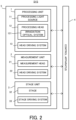
- the measurement unit 2 includes a measurement head 21 and a head driving system 22.
- the measurement head 21 is configured to measure (in other words, is configured to measure) the measurement target object under the control of the control unit 4. Specifically, the measurement head 21 is configured to measure any characteristic of the measurement target object.
- a position of the measurement target object is one example of the characteristic of the measurement target object.
- a shape (for example, a two-dimensional shape or a three-dimensional shape) of the measurement target object is another example of the characteristic of the measurement target object.
- At least one of a reflectance of the measurement target object, a transmittance of the measurement target object, a surface roughness of the measurement target object, and so on is another example of the characteristic of the measurement target object.
- the measurement head 21 may measure the measurement target object by using any measurement method.
- the measurement head 21 may measure the measurement target object optically, electrically, magnetically, physically, chemically, or thermally.
- the measurement head 21 may measure the measurement target object without contacting the measurement target object.
- the measurement head 21 may measure the measurement target object by contacting the measurement target object.
- the measurement head 21 may measure the measurement target object by using a light section method that projects the measurement light ML, which is a slit light, on the surface of the measurement target object and measures a shape of the projected slit light.
- the measurement head 21 may measure the measurement target object by using a white light interference method that measures an interference pattern of the measurement light ML, which is white light through the measurement target object, and white light not through the measurement target object.
- the measurement head 21 may measure the measurement target object by using at least one of a pattern projection method that projects the measurement light ML, which forms a light pattern on the surface of the measurement target object, and measures a shape of the projected pattern, and a time of flight method that performs an operation, which emits the measurement light ML to the surface of the measurement target object and measures a distance to the measurement target object based on an elapsed time until the emitted light returns, at plurality of positions on the measurement target object.
- a pattern projection method that projects the measurement light ML, which forms a light pattern on the surface of the measurement target object, and measures a shape of the projected pattern
- a time of flight method that performs an operation, which emits the measurement light ML to the surface of the measurement target object and measures a distance to the measurement target object based on an elapsed time until the emitted light returns, at plurality of positions on the measurement target object.
- the measurement head 21 may measure the measurement target object by using at least one of a moiré topography method ( specifically, a grid irradiation method or a grid projection method), a holography interference method, an auto collimation method, a stereo method, an astigmatism method, a critical angle method, a knife edge method, an interference measurement method and a confocal method.
- a moiré topography method specifically, a grid irradiation method or a grid projection method
- a holography interference method specifically, a holography interference method, an auto collimation method, a stereo method, an astigmatism method, a critical angle method, a knife edge method, an interference measurement method and a confocal method.
- the measurement head 21 may irradiate the workpiece W with the measurement light ML by emitting the measurement light ML downwardly from the measurement head 21. Namely, the measurement head 21 may irradiate the workpiece W with the measurement light ML propagating along the Z-axis direction by emitting the measurement light ML propagating along the Z-axis direction. The measurement head 21 may irradiate the workpiece W with the measurement light ML whose propagating direction is the Z-axis direction by emitting the measurement light ML whose propagating direction is the Z-axis direction.
- the measurement head 21 may include a plurality of measurement devices, each of which is configured to measure the measurement target object.
- the plurality of measurement devices may include at least two measurement devices whose measurement resolutions are different from each other (in other words, whose measurement accuracies are different from each other).
- the plurality of measurement devices may include at least two measurement devices whose sizes of measurement areas are different from each other.
- the plurality of measurement devices may include at least two measurement devices whose measurement methods are different from each other.
- the head driving system 22 moves the measurement head 21 along at least one of the X-axis direction, the Y-axis direction, the Z-axis direction, the ⁇ X direction, the ⁇ Y direction, and the ⁇ Z direction under the control of the control unit 4.
- FIG. 1 illustrates an example in which the head driving system 22 moves the measurement head 21 along the Z-axis direction.
- the head driving system 22 may include a Z slide member 221 extending along the Z-axis direction, for example.
- the Z slide member 221 is positioned at the support frame 6 that is positioned on the surface plate 31 through the vibration isolator.
- the Z slide member 221 is positioned at the beam member 62 through a support member 64 that extends along the Z-axis direction, for example.
- the measurement head 21 is connected to the Z slide member 221 so as to be movable along the Z slide member 221.
- moving the measurement head 21 may be considered to be equivalent to changing the positional relationship between the measurement head 21 and each of the stage 32 and the workpiece W.
- the processing head 12 may include a measurement device that is configured to measure the measurement target object.
- the stage unit 3 includes the surface plate 31, the stage 32, and the stage driving system 33.
- the stage 32 is a placing apparatus on which the workpiece W is placed.
- the stage 32 may be configured to hold the workpiece W placed on the stage 32.
- the stage 32 may include at least one of a mechanical chuck, an electrostatic chuck, and a vacuum suction chuck to hold the workpiece W.
- the stage 32 may not be configured to hold the workpiece W placed on the stage 32. In this case, the workpiece W may be placed on the stage 32 without a clamp.
- the stage driving system 33 moves the stage 32 under the control of the control unit 4.
- the stage driving system 33 may move the stage 32 along at least one of the X-axis direction, the Y-axis direction, the Z-axis direction, the ⁇ X direction, the ⁇ Y direction, and the ⁇ Z direction under the control of the control unit 4.
- the stage driving system 33 moves the stage 32 along each of the X-axis and the Y-axis. Namely, in the example illustrated in FIG. 1 , the stage driving system 33 moves the stage 32 along a direction that is along the XY plane intersecting the propagating direction of each of the processing light EL and the measurement light ML.
- the stage driving system 33 may include an X slide member 331 extending along the X-axis direction (in the example illustrated in FIG. 1 , two X slide members 331 positioned to be parallel to each other) and a Y slide member 332 extending along the Y-axis direction (in the example illustrated in FIG. 1 , one Y slide member 332), for example.
- the two X slide members 331 are positioned on the surface plate 31 so as to be aligned along the Y-axis direction.
- the Y slide member 332 is connected to the two X slide members 331 so as to be movable along the two X slide members 331.
- the stage 32 is connected to the Y slide member 332 so as to be movable along the Y slide member 332.
- the stage 32 may be supported to float on the surface plate 31 by an air bearing.
- stage driving system 33 moves the stage 32
- the positional relationship between each of the processing head 12 and measurement head 21 and each of the stage 32 and the workpiece W changes. Furthermore, when the stage driving system 33 moves the stage 32, each of the stage 32 and the workpiece W moves relative to each of the processing area PSA in which the processing head 12 performs the subtractive manufacturing and the measurement area in which the measurement head 21 performs the measurement.
- the control unit 4 controls an operation of the processing system SYS.
- the control unit 4 may control the processing unit 1 and the stage unit 3 based on processing control data for controlling the processing system SYS to process the workpiece W.
- the processing control data may include processing path data.
- the processing path data may indicate a relative movement trajectory of the target irradiation area EA of the processing light EL on the surface of the workpiece W relative to the surface of the workpiece W.
- the processing path data may indicate a relative movement trajectory (so-called processing path) of the irradiation position of the processing light EL on the surface of the workpiece W relative to the surface of the workpiece W.
- the control unit 4 may control the measurement unit 2 and the stage unit 3 based on measurement control data for controlling the processing system SYS to measure the measurement target object.
- the control unit 4 may include a calculation apparatus and a storage apparatus.
- the calculation apparatus may include at least one of a CPU (Central Processing Unit) and a GPU (Graphic Processing Unit), for example.
- the storage apparatus may include a memory, for example.
- the control unit 4 serves as an apparatus for controlling the operation of the processing system SYS by means of the calculation apparatus executing a computer program.
- the computer program is a computer program that allows the calculation apparatus to execute (namely, to perform) a below-described operation that should be executed by the control unit 4.
- the computer program is a computer program that allows the control unit 4 to function so as to make the processing system SYS perform the below-described operation.
- the control unit 4 may not be positioned in the processing system SYS.
- the control unit 4 may be positioned at the outside of the processing system SYS as a server or the like.
- the control unit 4 may be positioned as a computer (for example, a laptop computer) that is connectable to the processing system SYS.
- the control unit 4 may be positioned as a computer (for example, a laptop computer) that is positioned in the vicinity of the processing system SYS.
- the control unit 4 may be connected to the processing system SYS through a wired and / or wireless network (alternatively, a data bus and / or a communication line).
- a network using an optical communication may be used as the wireless network.
- the control unit 4 and the processing system SYS may be configured to transmit and receive various information through the network.
- the control unit 4 may be configured to transmit information such as a command and a control parameter to the processing system SYS through the network.
- the processing system SYS may include a reception apparatus that is configured to receive the information such as the command and the control parameter from the control unit 4 through the network.
- a first control apparatus that is configured to perform a part of the processing performed by the control unit 4 may be positioned in the processing system SYS and a second control apparatus that is configured to perform another part of the processing performed by the control unit 4 may be positioned at an outside of the processing system SYS.
- the unit processing amount ⁇ z may be a depth by which the workpiece W is removed when the workpiece W is irradiated with the processing light EL having a unit number of pulse.
- the unit number of pulse may be 1 or may be a number that is equal to or larger than 1.
- the unit processing amount ⁇ z may be a processed amount (a removed depth) of the workpiece W when the workpiece W is irradiated with the processing light EL having a unit energy for a unit time.
- the material of the workpiece W included in the energy transmitted part is melted due to the heat caused by the energy of the processing light EL.
- the melted material spatters as liquid drop.
- the melted material evaporates due to the heat caused by the energy of the processing light EL.
- the target irradiation area EA and a part that is in vicinity of the target irradiation area EA of the workpiece W is removed.
- a concave part in other words, a groove part
- the processing system SYS moves the target irradiation area EA on the surface of the workpiece W along the processing path indicated by the processing path data by using the above-described Galvano mirror 1212. Namely, the processing system SYS scans the surface of the workpiece W with the processing light EL. The processing system SYS scans the surface of the workpiece W with the processing light EL along a scanning direction that intersects the propagating direction of the processing light EL. Furthermore, the processing system SYS may move the target irradiation area EA on the surface of the workpiece W along the processing path indicated by the processing path data by moving the processing head 12 using the above-described head driving system 13 and / or moving the stage 32 using the above-described stage driving system 33, if necessary.
- the processing system SYS may appropriately remove a part of the workpiece W on which the subtractive manufacturing should be performed by scanning the surface of the workpiece W with the processing light EL along a desired scanning trajectory corresponding to an area on which the subtractive manufacturing should be performed.
- the processing system SYS may appropriately remove the part of the workpiece W on which the subtractive manufacturing should be performed by scanning the surface of the workpiece W with the processing light EL along the desired scanning trajectory (namely, the processing path indicated by the processing path data) corresponding to the area on which the subtractive manufacturing should be performed.
- the processing system SYS may remove a removal layer SL, which has a thickness corresponding to the unit processing amount ⁇ z and which is the part on which the subtractive manufacturing should be performed, from the workpiece W by scanning the surface of the workpiece W with the processing light EL along the desired scanning trajectory corresponding to the area on which the subtractive manufacturing should be performed.
- the processing system SYS may process the workpiece W so that a shape of the workpiece W becomes a desired shape by repeating an operation for removing the removal layer SL having the thickness corresponding to the unit processing amount ⁇ z. Namely, the processing system SYS may process the workpiece W so that the shape of the workpiece W becomes the desired shape by removing a plurality of removal layers SL. Specifically, as illustrated in FIG. 4D , the processing system SYS processes the workpiece W so as to remove a target processing part TP, which should be removed by the subtractive manufacturing, of the workpiece W under the control of the control unit 4. On the other hand, the processing system SYS processes the workpiece W so as not to remove a non-target processing part NP, which should not be removed by the subtractive manufacturing, of the workpiece W under the control of the control unit 4.
- the target processing part TP is removed from the workpiece W, and the non-target processing part NP of the workpiece W remains.
- the processing system SYS may process the workpiece W so that a shape (for example, a three-dimensional shape) of the remaining non-target processing part NP becomes a target shape under the control of the control unit 4.
- the processing system SYS may perform a wall forming operation for forming a wall part WP with a wall shape on a part of the workpiece W by performing the above-described subtractive manufacturing.
- FIG. 5A is a cross-sectional view that illustrates the workpiece W from which the target processing part TP is not removed and the workpiece W from which the target processing part TP has been removed
- FIG. 5B is a top view that illustrates the workpiece W from which the target processing part TP is not removed and the workpiece W from which the target processing part TP has been removed.
- the processing system SYS may process the workpiece W so that at least a part of the non-target processing part NP, which remains after the target processing part TP is removed, forms the wall part WP.
- the processing system SYS processes the workpiece W so that at least a part of the non-target processing part NP forms the wall part WP that surrounds a depression, which is formed in the workpiece W by removing the target processing part TP, from all sides.
- the wall part WP may extend in the propagating direction of the processing light EL.
- the wall part WP may include a structure that extends along the propagating direction of the processing light EL.
- the propagating direction of the processing light EL is the Z-axis direction as described above.
- the wall part WP may extend along the Z-axis direction.
- the wall part WP may include a structure that extends along the Z-axis direction.
- the wall part WP (for example, at least a part of the wall part WP) may be approximately parallel to the propagating direction of the processing light EL.
- the wall part WP may include a structure that is approximately parallel to the propagating direction of the processing light EL.
- a state where "the wall part WP is approximately parallel to the propagating direction of the processing light EL" may include a state where "the wall part WP is literally completely parallel to the propagating direction of the processing light EL".
- the state where "the wall part WP is approximately parallel to the propagating direction of the processing light EL” may include a state where "the wall part WP is not completely parallel to the propagating direction of the processing light EL, but the wall part WP can be considered to be parallel to the propagating direction of the processing light EL".
- a state where "the wall part WP can be considered to be parallel to the propagating direction of the processing light EL” may include a state where "an angle ⁇ 1 between the wall part WP and the propagating direction of the processing light EL is equal to a first predetermined angle or smaller than the first predetermined angle" as illustrated in FIG. 6 that is a cross-sectional view illustrating the enlarged wall part WP.
- the first predetermined angle may be an angle that is equal to or smaller than 12 degrees.
- the first predetermined angle may be an angle that is equal to or smaller than 8 degrees.
- the state where "the wall part WP is completely parallel to the propagating direction of the processing light EL" may mean a state where "the angle ⁇ 1 between the wall part WP and the propagating direction of the processing light EL is 0 degrees".
- the angle ⁇ 1 between the wall part WP and the propagating direction of the processing light EL may mean ab angle between the wall part WP and an axis along the propagating direction of the processing light EL.
- At least a part of the wall surface WS may be an exposed surface Se that is exposed by removing the target processing part TP from the workpiece W. Namely, at least a part of the wall surface WS may be the exposed surface Se that is not visible from the outside of the workpiece W before the target processing part TP is removed from the workpiece W. At least a part of the wall surface WS may be an exposed surface Se that is visible from the outside of the workpiece W after the target processing part TP is removed from the workpiece W.
- the wall surface WS (for example, at least a part of the wall surface WS) may be approximately parallel to the propagating direction of the processing light EL.
- the wall surface WS may include a surface that is approximately parallel to the propagating direction of the processing light EL.
- a state where "the wall surface WS is approximately parallel to the propagating direction of the processing light EL" may include a state where "the wall surface WS is literally completely parallel to the propagating direction of the processing light EL".
- the state where "the wall surface WS is approximately parallel to the propagating direction of the processing light EL” may include a state where "the wall surface WS is not completely parallel to the propagating direction of the processing light EL, but the wall surface WS can be considered to be parallel to the propagating direction of the processing light EL".
- a state where "the wall surface WS can be considered to be parallel to the propagating direction of the processing light EL” may include a state where "an angle ⁇ 2 between the wall surface WS and the propagating direction of the processing light EL is equal to a second predetermined angle or smaller than the second predetermined angle" as illustrated in FIG. 6 that is the cross-sectional view illustrating the enlarged wall surface WS.
- the second predetermined angle may be an angle that is equal to or smaller than 12 degrees.
- the second predetermined angle may be an angle that is equal to or smaller than 8 degrees.
- the state where "the wall surface WS is completely parallel to the propagating direction of the processing light EL" may mean a state where "the angle ⁇ 2 between the wall surface WS and the propagating direction of the processing light EL is 0 degrees".
- a normal NL of the wall surface WS may intersect the propagating direction of the processing light EL, as illustrated in FIG. 6 that is the cross-sectional view illustrating the enlarged wall surface WS.
- the normal NL of the wall surface WS may intersect the Z-axis direction. In this case, as illustrated in FIG.
- the third predetermined angle may be an angle that is equal to or larger than 78 degrees.
- the third predetermined angle may be an angle that is equal to or larger than 82 degrees.
- the state where "the angle ⁇ 3 is approximately 90 degrees” may include a state where "the angle ⁇ 3 is larger than 90 degrees, but the angle ⁇ 3 can be considered to be 90 degrees".
- a state where "the angle ⁇ 3, which is larger than 90 degrees, can be considered to be 90 degrees” may include a state where "the angle ⁇ 3 is smaller than a fourth predetermined angle".
- the fourth predetermined angle may be an angle that is equal to or smaller than 102 degrees.
- the fourth predetermined angle may be an angle that is equal to or smaller than 98 degrees.
- the upper surface Su of the non-target processing part NP may be a surface facing upwardly (for example, toward the +Z side).
- the upper surface Su of the non-target processing part NP may be an upper part of a surface of the non-target processing part NP.
- the upper part of the surface of the non-target processing part NP may be a surface that is positioned above the other surface of the surface of the non-target processing part NP.
- the upper surface Su of the non-target processing part NP may be a surface that is connected to an upper end (for example, an end at the +Z side end) of the wall part WP.
- the upper surface Su of the non-target processing part NP may include a surface that is exposed before the target processing part TP is removed from the workpiece W.
- a state where "the angle ⁇ 4, which is smaller than 90 degrees, can be considered to be 90 degrees” may include a state where "the angle ⁇ 4 is larger than a fifth predetermined angle".
- the fifth predetermined angle may be an angle that is equal to or larger than 78 degrees.
- the fifth predetermined angle may be an angle that is equal to or larger than 82 degrees.
- the state where "the angle ⁇ 4 is approximately 90 degrees” may include a state where "the angle ⁇ 4 is larger than 90 degrees, but the angle ⁇ 4 can be considered to be 90 degrees”.
- a state where "the angle ⁇ 4, which is larger than 90 degrees, can be considered to be 90 degrees” may include a state where "the angle ⁇ 4 is smaller than a sixth predetermined angle".
- the sixth predetermined angle may be an angle that is equal to or smaller than 102 degrees.
- the sixth predetermined angle may be an angle that is equal to or smaller than 98 degrees.
- the bottom surface Sb of the non-target processing part NP may be a surface facing upwardly (for example, toward the +Z side). Especially, the bottom surface Sb of the non-target processing part NP may be a surface that is connected to a lower end (for example, an end at the -Z side end) of the wall part WP.
- the bottom surface Sb of the non-target processing part NP may include the exposed surface Se that is exposed by removing the target processing part TP from the workpiece W.
- the bottom surface Sb of the non-target processing part NP may include a surface that forms a bottom of a depression that is formed by removing the target processing part TP from the workpiece W.
- the wall surface WS of the wall part WP may satisfy a condition that an angle ⁇ 5 between the upper surface Su of the non-target processing part NP and the wall surface WS is approximately 90 degrees, as illustrated in FIG. 7 that is the cross-sectional view illustrating the enlarged wall surface WS.
- a state where "the angle ⁇ 5 is approximately 90 degrees” may include a state where "the angle ⁇ 5 is literally completely equal to 90 degrees”.
- the state where "the angle ⁇ 5 is approximately 90 degrees” may include a state where "the angle ⁇ 5 is smaller than 90 degrees, but the angle ⁇ 5 can be considered to be 90 degrees".
- the wall surface WS may satisfy a condition that an angle ⁇ 6 between the bottom surface Sb of the non-target processing part NP and the wall surface WS is approximately 90 degrees, as illustrated in FIG. 7 that is the cross-sectional view illustrating the enlarged wall surface WS.
- a state where "the angle ⁇ 6 is approximately 90 degrees” may include a state where "the angle ⁇ 6 is literally completely equal to 90 degrees".
- the state where "the angle ⁇ 6 is approximately 90 degrees” may include a state where "the angle ⁇ 6 is smaller than 90 degrees, but the angle ⁇ 6 can be considered to be 90 degrees”.
- a state where "the angle ⁇ 6, which is smaller than 90 degrees, can be considered to be 90 degrees” may include a state where "the angle ⁇ 6 is larger than a ninth predetermined angle".
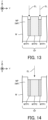
- FIG. 8A and FIG. 8B illustrate examples of the first part WTP1 and the second part WTP2 that are set to form the wall part WP illustrated in FIG. 5 .
- FIG. 8A is a cross-sectional view that illustrates examples of the first part WTP1 and the second part WTP2 of the target processing part TP
- FIG. 8B is a top view that illustrates examples of the first part WTP1 and the second part WTP2 of the target processing part TP.
- control unit 4 may determine the second part WTP2 based on the shape of the target processing part TP. Even in this case, once the second part WTP2 is determined, the first part WTP1 is automatically determined. Namely, the control unit 4 may indirectly determine the first part WTP1 by determining the second part WTP2. Therefore, the operation for determining the second part WTP2 may be effectively included in the operation for determining the first part WTP1.
- the shape of the target processing part TP may include a distance (in other words, a length or a depth) Dis1 (see FIG. 8A ) of the target processing part TP in a direction along the wall part WP.
- the distance Dis1 of the target processing part TP in the direction along the wall part WP may mean a distance (a length or a depth) of the target processing part TP in the direction along the wall surface WS.
- the control unit 4 may determine at least one of the first part WTP1 and the second part WTP2 based on the distance Dis1 of the target processing part TP along the wall part WP.
- the control unit 4 may determine at least one of the first part WTP1 and the second part WTP2 so that a width (specifically, a size along the adjacent direction) of the first part WTP1 becomes larger as the distance Dis1 becomes longer.
- the shape of the target processing part TP may include a distance Dis2 (see FIG. 6 ) between the upper end of the wall part WP and the lower end of the wall part WP in the adjacent direction.
- the control unit 4 may determine at least one of the first part WTP1 and the second part WTP2 based on the distance Dis2. For example, the control unit 4 may determine at least one of the first part WTP1 and the second part WTP2 so that the width (specifically, the size along the adjacent direction) of the first part WTP1 becomes larger as the distance Dis2 becomes larger.
- the control unit 4 may generate the processing control data so that a processing condition for removing the first part WTP1 is different from a processing condition for removing the second part WTP2.
- the control unit 4 may generate the processing control data so that the processing condition is a first processing condition in a case where the first part WTP1 is removed and the processing condition is a second processing condition that is different from the first condition in a case where the second part WTP2 is removed.
- the processing system SYS may perform the first subtractive manufacturing operation for removing at least a part of the first part WTP1 by irradiating the first part WTP1 with the processing light EL having the first light condition.
- the processing system SYS may perform the second subtractive manufacturing operation for removing at least a part of the second part WTP2 by irradiating the second part WTP2 with the processing light EL having the second light condition.
- the light condition related to the processing light EL may include a condition related to a fluence of the processing light EL.
- the control unit 4 may generate the processing control data so that the fluence of the processing light EL that is irradiated onto the first part WTP1 for removing the first part WTP1 is different from the fluence of the processing light EL that is irradiated onto the second part WTP2 for removing the second part WTP2.
- FIG. 10A illustrates the processing light EL entering the surface of the workpiece W at a first incident angle.
- FIG. 10B illustrates the processing light EL entering the surface of the workpiece W at a second incident angle that is larger than the first incident angle.
- an area that is actually irradiated with the processing light EL on the surface of the workpiece W is larger as the incident angle of the processing light EL is larger.
- the wall part WP namely, the exposed surface Se that has been already exposed
- the wall part WP namely, the exposed surface Se that has been already exposed
- the second part WTP2 that is not adjacent to the wall part WP is processed. Therefore, in a case where the first part WTP1 that is adjacent to the wall part WP is processed, there is a higher possibility that the incident angle of the processing light EL is larger, compared to the case where the second part WTP2 that is not adjacent to the wall part WP is processed.
- the processed amount of the first part WTP1 is insufficient and the wall part WP is unintentionally formed so that the angle ⁇ 3 (see FIG. 7 ) between the upper surface Su of the non-target processing part NP and the wall part WP is smaller than a desired angle.
- the processed amount of the first part WTP1 is insufficient and the wall part WP that is inclined with respect to the Z-axis direction (namely, that does not rise vertically) is unintentionally formed in a situation where the wall part WP that extends along the Z-axis direction (namely, that rises vertically) should be formed.
- the processing system SYS can appropriately form the wall part WP so that the angle ⁇ 3 between the upper surface Su of the non-target processing part NP and the wall part WP is the desired angle.
- the processing system SYS can appropriately form the wall part WP that extends along the Z-axis direction (namely, that rises vertically) in a situation where the wall part WP that extends along the Z-axis direction (namely, that rises vertically) should be formed.
- the size of the beam spot BS of the processing light EL that is irradiated onto the second part WTP2 is larger than the size of the beam spot BS of the processing light EL that is irradiated onto the first part WTP1.
- a size of an area that is irradiated with the processing light EL on the workpiece W per unit time is larger as the size of the beam spot BS is larger.
- the processing system SYS may prioritize improving throughput over forming the appropriate wall part WP in the second part WTP2 at which it is not necessary to form the wall part WP by allowing the size of the beam spot BS of the processing light EL that is irradiated onto the second part WTP2 at which it is not necessary to form the wall part WP to be larger than the size of the beam spot BS of the processing light EL that is irradiated onto the first part WTP1.
- control unit 4 may generate the processing control data so that the irradiation number of times of the processing light EL is a predetermined first number in a case where the first part WTP1 is removed and the irradiation number of times of the processing light EL is a predetermined second number that is different from the first number in a case where the second part WTP2 is removed.
- the control unit 4 may generate the processing control data based on the measured result of the processed part by the test processing.
- the control unit 4 may generate the processing control data so that the fluence of the processing light EL is a desired fluence based on the measured results of the processing marks from the test processing.
- the control unit 4 may generate the processing control data the measured result of the processed part by the test processing so that the overlap rate of the processing light EL becomes the desired overlap rate.
- the control unit 4 may generate the processing control data the measured result of the processed part by the test processing so that the irradiation number of times of the processing light EL is a desired number of times.
- the control unit 4 may set the processing condition related to the processing light EL for performing the second subtractive manufacturing operation (namely, the processing light EL that is irradiated onto the second part WTP2) based on the measured result of the processed part by the test processing. Furthermore, the control unit 4 may set the processing light EL for performing the first subtractive manufacturing operation (namely, the processing light EL that is irradiated onto the first part WTP1) based on the processing condition related to the processing light EL for performing the second subtractive manufacturing operation. For example, the control unit 4 may set the fluence of the processing light EL for performing the second subtractive manufacturing operation (namely, the processing light EL that is irradiated onto the second part WTP2) based on the measured result of the processed part by the test processing.
- the processing system SYS may remove a part of the first part WTP1 by performing the first subtractive manufacturing operation. Specifically, the processing system SYS may remove a part of the first part WTP1 by scanning the surface of the first part WTP1 with the processing light EL. Namely, the processing system SYS may remove the removal layer SL that is a part of the first part WTP1. In this case, the processing system SYS may remove a single removal layer SL by a single first removal manufacturing operation. In this case, the processing system SYS may remove the single removal layer SL by scanning the first part WTP1 once in a direction that intersects the propagating direction of the processing light EL.
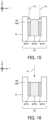
- the processing system SYS may remove a part of the second part WTP2 by performing the second subtractive manufacturing operation, as illustrated in FIG. 14 .
- the processing system SYS may remove a part of the second part WTP2 by scanning the surface of the second part WTP2 with the processing light EL.
- the processing system SYS may remove the removal layer SL that is a part of the second part WTP2.
- the processing system SYS may remove a single removal layer SL by a single second subtractive manufacturing operation.
- the processing system SYS may remove the single removal layer SL by scanning the second part WTP2 once in a direction that intersects the propagating direction of the processing light EL.
- the processing system SYS may remove a plurality of removal layers SL by the single second removal manufacturing operation.
- the processing system SYS may remove the plurality of removal layers SL by scanning the second part WTP2 a plurality of number of times in a direction that intersects the propagating direction of the processing light EL.
- the number of removal layers SL removed by the single first subtractive manufacturing operation may be the same as the number of removal layers SL removed by the single second subtractive manufacturing operation.
- the processing system SYS may perform the first subtractive manufacturing operation for removing N (wherein, N is a variable number representing an integer that is larger than or equal to 1) removal layers SL that are a part of the first part WTP1, and then perform the second subtractive manufacturing operation for removing N removal layers SL that are a part of the second part WTP2.
- the processing system SYS may perform the first subtractive manufacturing operation that includes an operation for removing the removal layer SL, which is a part of the first part WTP1, by N number of times, and the second subtractive manufacturing operation that includes an operation for removing the removal layer SL, which is a part of the second part WTP2, by N number of times.
- the number of removal layers SL removed by the single first subtractive manufacturing operation may be different from the number of removal layers SL removed by the single second subtractive manufacturing operation.
- the processing system SYS may perform the first subtractive manufacturing operation for removing N removal layers SL that are a part of the first part WTP1, and then perform the second subtractive manufacturing operation for removing M (wherein, M is a variable number representing an integer that is different from the variable number N and that is larger than or equal to 1) removal layers SL that are a part of the second part WTP2.
- the fluence of the processing light EL that is irradiated onto the first part WTP1 may be different from the fluence of the processing light EL that is irradiated onto the second part WTP2.
- the fluence of the processing light EL that is used by the first subtractive manufacturing operation may be different from the fluence that is used by the second subtractive manufacturing operation.
- the thickness (namely, the unit processing amount ⁇ z illustrated in FIG. 4 ) of the removal layer SL removed by the first subtractive manufacturing operation is different from the thickness of the removal layer SL removed by the second subtractive manufacturing operation.
- the number of removal layers SL removed by the single first subtractive manufacturing operation may be different from the number of removal layers SL removed by the single second subtractive manufacturing operation.
- the processing system SYS may perform the first and second subtractive manufacturing operations so that the total thickness of the N removal layers SL removed by the single first subtractive manufacturing operation is the same as the total thickness of the M removal layers SL removed by the single second subtractive manufacturing operation.
- the processing system SYS may perform the second subtractive manufacturing operation again. Namely, the processing system SYS may remove at least a part of the remaining second part WTP2 by performing the second subtractive manufacturing operation, as illustrated in FIG. 16 . Specifically, the processing system SYS may remove at least a part of the remaining second part WTP2 by scanning the surface of the remaining second part WTP2 with the processing light EL. Namely, the processing system SYS may remove the removal layer SL that is a part of the remaining second part WTP2.
- the processing system SYS repeats the same operation until the removal of the first part WTP1 and the second part WTP2 is completed. Namely, the processing system SYS repeats the same operation until the removal of the target processing part TP is completed.
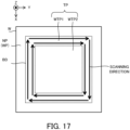
- the processing system SYS may scan the first part WTP1 with the processing light EL so that the scanning direction of the processing light EL on the surface of the workpiece W is the same as a direction along which the boundary BD between the target processing part TP and the non-target processing part NP extends on the surface of the workpiece W, as illustrated in FIG. 17 .
- the processing system SYS may scan the first part WTP1 with the processing light EL so that a positional relationship between the workpiece W and the irradiation position of the processing light EL is changed in the direction along which the boundary BD extends.
- the processing system SYS can process the workpiece W so as to form the appropriate wall part WP, compared to a case where the first part WTP1 is scanned with the processing light EL along a direction that is different from the direction along which the boundary BD extends.
- the processing system SYS can appropriately form the wall part WP so that the angle ⁇ 3 (see FIG. 7 ) between the upper surface Su of the non-target processing part NP and the wall part WP is the desired angle.
- the processing system SYS can appropriately form the wall part WP that extends along the Z-axis direction (namely, that rises vertically) in a situation where the wall part WP that extends along the Z-axis direction (namely, that rises vertically) should be formed.
- the processing system SYS may control (for example, change) an open angle of the processing light EL so that the open angle of the processing light EL in a case where the first part WTP1 is irradiated with the processing light EL is different from the open angle of the processing light EL in a case where the second part WTP2 is irradiated with the processing light EL.
- the processing system SYS may control (for example, change) the overlap ratio of the processing light EL so that the overlap ratio of the processing light EL in a case where the first part WTP1 is processed is different from the overlap ratio of the processing light EL in a case where the second part WTP2 is processed.
- the processing system SYS may control (for example, change) the size of the beam spot BS of the processing light EL so that the size of the beam spot BS of the processing light EL in a case where the first part WTP1 is processed is different from the size of the beam spot BS of the processing light EL in a case where the second part WTP2 is processed.
- the processing system SYS may control (for example, change) the scanning direction of the processing light EL so that the scanning direction of the processing light EL in a case where the first part WTP1 is processed is different from the scanning direction of the processing light EL in a case where the second part WTP2 is processed.
- the processing system SYS in the present example embodiment performs the first subtractive manufacturing operation for removing at least a part of the first part WTP1 of the target processing part TP and the second subtractive manufacturing operation for removing at least a part of the second part WTP2 of the target processing part TP in order to remove the target processing part TP to form the wall part WP. Therefore, the processing system SYS can process the workpiece W so as to form the appropriate wall part WP, compared to a processing system in a first comparison example that removes the target processing part TP without dividing the target processing part TP into the first part WTP1 and the second part WTP2. For example, the processing system SYS can appropriately form the wall part WP so that the angle ⁇ 3 (see FIG.
- the processing system SYS can appropriately form the wall part WP that extends along the Z-axis direction (namely, that rises vertically) in a situation where the wall part WP that extends along the Z-axis direction (namely, that rises vertically) should be formed, as illustrated in FIG. 18A .
- the processing system SYS forms the wall part WP that is inclined with respect to the Z-axis direction (namely, that does not rise vertically) as illustrated in FIG.
- the processing system SYS divides the target processing part TP into the first part WTP1 and the second part WTP2 under the control of the control unit 4.
- the processing system SYS may divide the target processing part TP into the first part WTP1, the second part WTP2, and a third part WTP3 under the control of the control unit 4. Namely, the processing system SYS may set a part of the target processing part TP to the first part WTP1, another part of the target processing part TP to the second part WTP2, and the remaining part of the target processing part TP to the third part WTP3 under the control of the control unit 4.
- FIG. 19 illustrates examples of the first part WTP1, the second part WTP2, and the third part WTP3 that are set to form the wall part WP illustrated in FIG. 5 .
- FIG. 19 is a cross-sectional view illustrating examples of the first part WTP1, the second part WTP2, and the third part WTP3 of the target processing part TP.
- the control unit 4 may set the third part WTP3 so that a size (in this case, a height in the Z-axis direction, and a thickness) of the third part WTP3 along the propagating direction of the processing light EL is a predetermined size.
- the control unit 4 may set the third part WTP3 having the predetermined size so that the target processing part TP having the predetermined size remains after the removal of the first part WTP1 and the second part WTP2 is completed.
- the control unit 4 may set the predetermined size based on a size of the target processing part TP.
- the size of the target processing part TP may include the distance (in other words, the length or the depth) Dis1 (see FIG. 8A ) in a direction along the wall part WP of the target processing part TP.
- the control unit 4 may set the predetermined size so that a predetermined percentage of the size of the target processing part TP is the predetermined size.
- the control unit 4 may set the predetermined size so that a size equivalent to 20% of the size of the target processing part TP or a size equivalent to 20% or more of the size of the target processing part TP is the predetermined size.
- the processing system SYS may process the workpiece W so that the target processing part TP having a size equivalent to 20% or more of the original size remains after the removal of the first part WTP1 and the second part WTP2 is completed.
- the control unit 4 may set the predetermined size so that a size equivalent to 10% of the size of the target processing part TP or a size equivalent to 10% or more of the size of the target processing part TP is the predetermined size.
- the processing system SYS may process the workpiece W so that the target processing part TP having a size equivalent to 10% or more of the original size remains after the removal of the first part WTP1 and the second part WTP2 is completed.
- control unit 4 may set the predetermined size so that a size equivalent to 5% of the size of the target processing part TP or a size equivalent to 10% or more of the size of the target processing part TP is the predetermined size.
- the processing system SYS may process the workpiece W so that the target processing part TP having a size equivalent to 5% or more of the original size remains after the removal of the first part WTP1 and the second part WTP2 is completed.
- the processing system SYS may remove the first part WTP1 and the second part WTP2 of the target processing part TP by performing the first subtractive manufacturing operation for irradiating at least a part of the first part WTP1 with the processing light EL to remove at least a part of the first part WTP1 and the second subtractive manufacturing operation for irradiating at least a part of the second part WTP2 with the processing light EL to remove at least a part of the second part WTP2, under the control of the control unit 4.
- the processing system SYS may remove the first part WTP1 and the second part WTP2 of the target processing part TP by alternately repeating the first subtractive manufacturing operation and the second subtractive manufacturing operation.
- the processing system SYS may remove the third part WTP3 of the target processing part TP by performing a third subtractive manufacturing operation for irradiating at least a part of the third part WTP3 with the processing light EL to remove at least a part of the third part WTP3.
- the processing system SYS may remove the third part WTP3 of the target processing part TP by repeating the third subtractive manufacturing operation. In this manner, in the first modified example, the processing system SYS may remove the target processing part TP by removing the first part WTP1 and the second part WTP2 and then removing the third part WTP3.
- FIG. 20A is a cross-sectional view illustrating the workpiece W from which the first part WTP1 and the second part WTP2 are removed without setting the third part WTP3.
- the wall part WP is formed, there is a possibility that at least one of the first part WTP1 and the second part WTP2 is unintentionally processed at a timing that is different from a timing at which at least one of the first part WTP1 and the second part WTP2 should be processed.
- FIG. 20A is a cross-sectional view illustrating the workpiece W from which the first part WTP1 and the second part WTP2 are removed without setting the third part WTP3.
- the second part WTP2 is further processed at the timing at which the second part WTP2 should be processed, and therefore, there is a possibility that the processed amount of the second part WTP2 is larger than the processed amount that is originally expected. As a result, a technical problem occurs that the non-target processing part NP, which is positioned under the second part WTP2, is unintentionally processed.
- the non-target processing part NP is unintentionally processed as the thickness of the remaining first part WTP1 and second part WTP2 is thinner. Namely, there is a possibility that the non-target processing part NP is unintentionally processed in a case where the thickness of the remaining first part WTP1 and second part WTP2 is thinner than a certain size.
- the non-target processing part NP which is positioned under the first part WTP1 or the second part WTP2, is unintentionally processed even when the first part WTP1 or the second part WTP2 is processed at the timing that is different from the timing at which the first part WTP1 or the second part WTP2 should be processed.
- FIG. 20B is a cross-sectional view illustrating the workpiece W in which the first part WTP1, the second part WTP2, and the third part WTP3 are set. Therefore, as illustrated in FIG. 20B that is a cross-sectional view illustrating the workpiece W in which the first part WTP1, the second part WTP2, and the third part WTP3 are set, there is a low possibility that the non-target processing part NP is unintentionally processed even when the first part WTP1 or the second part WTP2 is processed at the timing that is different from the timing at which the first part WTP1 or the second part WTP2 should be processed.
- the control unit 4 may set the size (in this case, the length in the Z-axis direction, and the thickness) of the third part WTP3 along the propagating direction of the processing light EL so that the third part WTP3 has a size that realizes a situation where the non-target processing part NP is not processed even when the first part WTP1 or the second part WTP2 is processed at the timing that is different the timing at which the first part WTP1 or the second part WTP2 should be processed.
- the processing condition for removing the third part WTP3 may be the same as the above-described processing condition for removing the second part WTP2.
- the light condition of the processing light EL that is irradiated onto the third part WTP3 for removing the third part WTP3 may be the same as the light condition of the processing light EL that is irradiated onto the second part WTP2 for removing the second part WTP2.
- the fluence of the processing light EL that is irradiated onto the third part WTP3 for removing the third part WTP3 may be the same as the fluence of the processing light EL that is irradiated onto the second part WTP2 for removing the second part WTP2.
- the fluence of the processing light EL that is irradiated onto the third part WTP3 for removing the third part WTP3 may be lower than the fluence of the processing light EL that is irradiated onto the first part WTP1 for removing the first part WTP1.
- the non-target processing part NP is unintentionally processed by the processing light EL reflected by the wall surface WS of the wall part WP, compared to a case where the fluence of the processing light EL that is irradiated onto the third part WTP3 for removing the third part WTP3 is higher than the fluence of the processing light EL that is irradiated onto the second part WTP2 for removing the second part WTP2.
- the processing condition for removing a part of the third part WTP may be different from the processing condition for removing another part of the third part WTP.
- the processing condition for processing a part of the third part WTP that is adjacent to the non-target processing part NP may be different from the processing condition for processing the remaining part of the third part WTP.
- the processing condition for processing a part of the third part WTP3 that is adjacent to the non-target processing part NP may be the same as the processing condition for removing the first part WTP1 described above.
- the processing condition for processing the remaining part of the third part WTP may be the same as the processing condition for removing the second part WTP2 described above.
- the processing system SYS can form the wall part WP that extends in the Z-axis direction (namely, rises vertically) more appropriately, compared to a case where the processing condition for processing a part of the third part WTP that is adjacent to the non-target processing part NP is the same as the processing condition for processing the remaining part of the third part WTP.
- the processing condition for processing a part of the third part WTP that is adjacent to the non-target processing part NP may be the same as the processing condition for processing the remaining part of the third part WTP.
- the processing system SYS may measure the shape of the third part WTP3 (namely, the remaining part of the target processing part TP) even after starting the third subtractive manufacturing operation for removing at least a part of the third part WTP3. Then, the processing system SYS may continue the third subtractive manufacturing operation based on the measured result of the third part WTP3 (namely, the remaining target processing part TP). As a result, the processing system SYS can perform the third subtractive manufacturing operation with high accuracy.
- control unit 4 may automatically set the size of the third part WTP3 (for example, the ratio of the size of the third part WTP3 to the target processing part TP before the removal) by considering a trade-off between an effect of improving the throughput of the processing system SYS and an effect of reducing the possibility of unintentional processing of the non-target processing part NP.
- an operator of the processing system SYS may manually set the size of the third part WTP3 (for example, the ratio of the size of the third part WTP3 to the target processing part TP before the removal).
- the processing system SYS may measure the remaining target processing part TP (for example, at least a part of the first part WTP1 and the second part WTP2) by using the measurement unit 2 in at least a part of the period during which the first and second subtractive manufacturing operations are performed to remove the first part WTP1 and the second part WTP2.
- the processing system SYS may remove at least a part of the first part WTP1 and the second part WTP2 based on a measured result of at least a part of the first part WTP1 and the second part WTP2 (namely, the remaining target processed part TP).
- the processing system SYS may perform the operation described in the first modified example for a purpose that is different form a purpose of preventing the unintentional processing of the non-target processing part NP due to the processing of the first part WTP1.
- the processing system SYS may perform the operation described in the first modified example for a purpose of improving a beauty of the bottom surface Sb of the non-target processing part NP.
- the processing system SYS may perform the operation described in the first modified example for a purpose of reducing color irregularity of the bottom surface Sb.
- the processing system SYS may perform the operation described in the first modified example for a purpose of reducing surface roughness of the bottom surface Sb.
- the unnecessary substance may include a substance (so-called debris) that is generated from a part of the workpiece W (especially, the target processing part TP) being molten, evaporated, or sublimated.
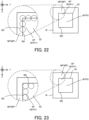
- the processing system SYS may irradiate the exposed surface Se with the processing light EL in order to remove the unnecessary substance adhered to the exposed surface Se, as illustrated in FIG. 21 .
- the processing system SYS may irradiate the exposed surface Se with the processing light EL so that the unnecessary substance adhered to the exposed surface Se is irradiated with the processing light EL.
- the unnecessary substance adhered to the exposed surface Se is molten, evaporated, or sublimated by the processing light EL, and therefore, the unnecessary substance is removed from the exposed surface Se.
- the processing system SYS may irradiate the exposed surface Se with the processing light EL after completing the removal of the target processing part TP.
- the processing system SYS may irradiate the exposed surface Se with the processing light EL before completing the removal of the target processing part TP.
- the processing system SYS may irradiate the exposed surface Se with the processing light EL after removing a predetermined amount of the target processing part TP.
- the processing condition for removing the unnecessary substance from the exposed surface Se may be the same as the processing condition for removing the second part WTP2 described above.
- the light condition of the processing light EL irradiated onto the exposed surface Se to remove the unnecessary substance may be the same as the light condition of the processing light EL irradiated onto the second part WTP2 to remove the second part WTP2.
- the fluence of the processing light EL irradiated onto the exposed surface Se to remove the unnecessary substance may be the same as the fluence of the processing light EL irradiated onto the second part WTP2 to remove the second part WTP2.
- the processing condition for removing the unnecessary substance from the exposed surface Se may be different from the processing condition for removing the second part WTP2 described above.
- the fluence of the processing light EL irradiated onto the exposed surface Se for removing the unnecessary substance may be lower than the fluence of the processing light EL irradiated onto the second part WTP2 for removing the second part WTP2.
- the intensity of the processing light EL irradiated onto the exposed surface Se may be lower than the intensity of the processing light EL irradiated onto the second part WTP2.
- the processing system SYS may remove the unnecessary substance from the exposed surface Se by using the principle of non-thermal processing.
- the processing system SYS may remove the unnecessary substance from the exposed surface Se by irradiating the exposed surface Se with the processing light EL that includes the pulsed light the ON time of which is equal to or shorter than pico-seconds or femto-seconds.
- the processing system SYS can remove the unnecessary substance from the exposed surface Se while reducing the influence on the exposed surface Se due to the heat caused by the energy of the processing light EL.
- the processing system SYS may measure the exposed surface Se by using the measurement unit 2 before irradiating the exposed surface Se with the processing light EL. Then, the control unit 4 may calculate a position to which the unnecessary substance is adhered on the exposed surface Se based on a measured result of the exposed surface Se. As one example, the control unit 4 may calculate the position to which the unnecessary substance is adhered on the exposed surface Se by calculating a difference between an actual shape of the exposed surface Se indicated by the measured result by the measurement unit 2 and a designed shape of the exposed surface Se. Alternatively, a user of the processing system SYS may input, into the processing system SYS, information related to the position to which the unnecessary substance is adhered on the exposed surface Se.
- control unit 4 may control the processing unit 1 and the stage unit 3 so as to irradiate the position to which the unnecessary substance is adhered on the exposed surface Se with the processing light EL.
- control unit 4 may control the processing unit 1 and the stage unit 3 so as to irradiate a position, which is calculated as the position to which the unnecessary substance is adhered on the exposed surface Se with the processing light EL.
- the processing system SYS can appropriately remove the unnecessary substances adhered to the exposed surface Se.
- the processing system SYS may rotate the stage 32 around a rotational axis that extends in a direction intersecting the propagating direction of the processing light EL by using the stage driving system 33 before irradiating the exposed surface Se with the processing light EL or after starting to irradiate the exposed surface Se with the processing light EL.
- the processing system SYS may rotate the stage 32 around at least one rotational axis of a rotational axis along the X-axis and a rotational axis along the Y-axis by using the stage driving system 33.
- the processing system SYS may rotate the stage 33 so that the exposed surface Se is a surface intersecting the propagating direction of the processing light EL. Then, the processing system SYS may irradiate the exposed surface Se with the processing light EL. As a result, the processing system SYS can easily irradiate the exposed surface Se with the processing light EL, compared to a case where the exposed surface Se is a surface along the propagating direction of the processing light EL. Therefore, the processing system SYS can appropriately remove the unnecessary substance from the exposed surface Se.
- the processing system SYS may rotate the processing head 12 around a rotational axis that extends in a direction intersecting the propagating direction of the processing light EL by using the head driving system 13 before irradiating the exposed surface Se with the processing light EL or after starting to irradiate the exposed surface Se with the processing light EL.
- the processing system SYS may rotate the processing head 12 around at least one rotational axis of a rotational axis along the X-axis and a rotational axis along the Y-axis by using the head driving system 13.
- the processing system SYS may set the operation mode of the processing system SYS to a first mode.
- the processing system SYS may set the operation mode of the processing system SYS to a second mode that is different from the first mode.
- the processing system SYS may switch the operation mode of the processing system SYS between the first mode and the second mode.
- the predetermined intensity may be set to the intensity of the processing light EL by which the subtractive manufacturing of the workpiece W can be performed.
- the predetermined intensity may be set to a threshold value that allows the intensity of the processing light EL that is high enough to perform the subtractive manufacturing of the workpiece W to be distinguished from the intensity of the processing light EL that is not high enough to perform the subtractive manufacturing of the workpiece W based on the intensity of the processing light EL.
- the predetermined intensity may be set to a threshold value that allows the intensity of the processing light EL that is high enough to perform the subtractive manufacturing of the workpiece W to be distinguished from the intensity of the processing light EL that is too low to perform the subtractive manufacturing of the workpiece W based on the intensity of the processing light EL.
- the predetermined intensity may be set based on a peak intensity in the intensity distribution of the processing light EL.
- the predetermined intensity may be set to an intensity that is obtained by multiplying the peak intensity by K (wherein, K is a variable number representing a real number that is larger than 0 and smaller than 1). 1/e 2 (wherein, e means Napier's constant) or 0.135 is one example of the variable K, in a case where the processing EL is a Gaussian beam. 0.135 is another example of the variable K, in a case where the processing EL is the Gaussian beam.
- FIG. 22 illustrates one example of the positional relationship between the boundary BD and the beam spot BS in the first mode.
- the first mode may be an operation mode in which the workpiece W is processed in a state where a center of the beam spot BS is positioned on the boundary BD on the surface of the workpiece W.
- the beam spot BS may mean the area that is irradiated with the light component, whose intensity is equal to or higher than the predetermined intensity, of the processing light EL. Therefore, the state "where the beam spot BS is positioned only in the inside of the target processing part TP that is away from the boundary BD" may mean a state where the area that is irradiated with the light component, whose intensity is equal to or higher than the predetermined intensity, of the processing light EL is positioned only in the inside of the target processing part TP that is away from the boundary BD.
- the boundary BD may be irradiated with light component, whose intensity is lower than the predetermined intensity, of the processing light EL.
- the non-target processing part NP that is outside the boundary BD may be irradiated with the light component, whose intensity is lower than the predetermined intensity, of the processing light EL.
- the fact remains that the inside of the target processing part TP that is away from the boundary BD is irradiated with the light component, whose intensity is equal to or higher than the predetermined intensity, of the processing light EL, and therefore, it can be said that the beam spot BS is positioned only in the inside of the target processing part TP that is away from the boundary BD.
- the control unit 4 may generate second processing control data for processing the workpiece W in the state where the center of the beam spot BS is away from the boundary BD.
- the control unit 4 may generate the second processing control data for controlling the center position of the beam spot BS so that the center of the beam spot BS moves at a position on the surface of the workpiece W that is away from the boundary BD.
- the control unit 4 may generate the second processing control data that includes second processing path data for controlling the center position of the beam spot BS so that the center of the beam spot BS moves along a second processing path that is away from the boundary BD on the surface of the workpiece W.
- control unit 4 may generate the second processing control data that includes the second processing path data for controlling the center position of the beam spot BS so that the center of the beam spot BS is positioned only in the inside of the target processing part TP that is away from the boundary BD.
- control unit 4 may generate the second processing control data that includes the second processing path data for controlling the center position of the beam spot BS so that the beam spot BS is positioned only in the inside of the target processing part TP that is away from the boundary BD.
- control unit 4 may generate the second processing control data that includes the second processing path data for controlling the center position of the beam spot BS so that the center of the beam spot BS is positioned on an outside of the boundary BD (namely, on the non-target processing part NP).
- the processing system SYS can process the workpiece W in the second mode based on the second processing control data generated by the control unit 4.
- the processing system SYS may process the workpiece W in the second mode based on the first processing control data that is for setting the operation mode of the processing system SYS to the first mode.
- the first processing control data is the processing control data for moving the center of the beam spot BS along the first processing path on the boundary BD, as described above.
- the control unit 4 may change (in other words, modify) the first processing path so that the first processing path is away from the boundary BD toward the inside of the target processing part TP to thereby generate the changed first processing path as the second processing path.
- the control unit 4 may change the first processing control data so that the first processing path is away from the boundary BD toward the inside of the target processing part TP to thereby generate the changed first processing control data as the second processing control data.
- the processing system SYS can process the workpiece W in the second mode based on the first processing path that has been changed by the control unit 4 (namely, the second processing path that has been generated from the first processing path by the control unit 4). Namely, the processing system SYS can process the workpiece W in the second mode based on the first processing control data that has been changed by the control unit 4 (namely, the second processing control data that has been generated from the first processing control data by the control unit 4).
- the processing system SYS may include an acquisition unit 41, an output unit 42, and a control unit 43 as a part of the control unit 4, as illustrated in FIG. 24 that illustrates one example of the configuration of the processing system SYS in the third modified example.
- the processing system SYS may include at least one of the acquisition unit 41, the output unit 42, and the control unit 43 as an apparatus that is different from the control unit 4.
- the acquisition unit 41 may further acquire information related to the processing light EL.
- the acquisition unit 41 may acquire information related to the size of the beam spot BS as at least a part of the information related to the processing light EL.
- the output unit 42 may change the first processing control data acquired by the acquisition unit 41 to thereby generate the second processing control data.
- the output unit 42 may change the first processing control data based on the information related to the processing light EL acquired by the acquisition unit 41.
- the output unit 42 may change the first processing control data so that the first processing path indicated by the first processing control data is away from the boundary BD by the predetermined distance based on the size of the beam spot BS. Then, the output unit 42 may output the changed first processing control data to the control unit 43 as the second processing control data.
- the control unit 43 may control at least one of the processing unit 1 and the stage unit 3 to process the workpiece W based on the second processing control data (namely, the changed first processing control data) output from the output unit 42.
- the operation mode of the processing system SYS may be manually selected (in other words, determined or set) by the user of the processing system SYS.
- the user may select either one of the first and second modes as the operation mode of the processing system SYS based on the characteristic (for example, the type) of the workpiece W that should be processed by the processing system SYS.
- the first mode is the operation mode in which the center of the beam spot BS is positioned on the boundary BD, as illustrated in FIG. 22 . Therefore, there is a possibility that the beam spot BS is formed on the non-target processing part NP that is outside the boundary BD. As a result, there is a possibility that the non-target processing part NP, which should not be processed, is unintentionally processed. Specifically, as illustrated in FIG. 25A that illustrates the workpiece W processed by the processing system SYS in the first mode, there is a possibility that a part of the non-target processing part NP, which remains as the wall part WP and which should not be processed, is unintentionally removed. As a result, there is a possibility that the size of the remaining wall part WP is different from the designed size.
- the processing system SYS can appropriately remove the target processing part TP so that the non-target processing part NP, which should not be processed, remains as the wall part WP.
- a processing system including:
- non-target processing part includes a wall part that extends along the propagating direction.
- a thickness of the first removal part which is removed by performing a scanning of the energy beam along a direction intersecting the propagating direction one time in the first operation, is different from a thickness of the second removal part, which is removed by performing a scanning of the energy beam along a direction intersecting the propagating direction one time in the second operation.
- control apparatus controls the processing apparatus to alternately repeat the first and second operations and then to remove at least another part of the target processing part by repeating the second operation.
- the processing system further including a measurement apparatus that is configured to measure another part of the target processing part after a part of the target processing part is removed by alternately repeating the first and second operations, wherein the control apparatus controls the processing apparatus to remove another part of the target processing part by repeating the second operation based on a measured result by the measurement apparatus.
- a processing system including:
- control apparatus performs the subtractive manufacturing of the part adjacent to the non-target processing part in a state where the center of the beam spot is positioned at a position that is away from the boundary by a predetermined distance on the surface of the object in the second mode.
- a processing system including:
Landscapes
- Engineering & Computer Science (AREA)
- Physics & Mathematics (AREA)
- Optics & Photonics (AREA)
- Plasma & Fusion (AREA)
- Mechanical Engineering (AREA)
- Laser Beam Processing (AREA)
Applications Claiming Priority (1)
| Application Number | Priority Date | Filing Date | Title |
|---|---|---|---|
| PCT/JP2022/022099 WO2023233514A1 (ja) | 2022-05-31 | 2022-05-31 | 加工システム |
Publications (1)
| Publication Number | Publication Date |
|---|---|
| EP4534232A1 true EP4534232A1 (de) | 2025-04-09 |
Family
ID=89025913
Family Applications (1)
| Application Number | Title | Priority Date | Filing Date |
|---|---|---|---|
| EP22944802.2A Pending EP4534232A1 (de) | 2022-05-31 | 2022-05-31 | Verarbeitungssystem |
Country Status (4)
| Country | Link |
|---|---|
| EP (1) | EP4534232A1 (de) |
| JP (1) | JPWO2023233514A1 (de) |
| CN (1) | CN119300948A (de) |
| WO (1) | WO2023233514A1 (de) |
Family Cites Families (6)
| Publication number | Priority date | Publication date | Assignee | Title |
|---|---|---|---|---|
| US4427872A (en) | 1978-09-22 | 1984-01-24 | Coherent, Inc. | Precision machining apparatus and method utilizing a laser |
| JP2719272B2 (ja) * | 1992-06-08 | 1998-02-25 | 富士通株式会社 | レーザを用いたプリント配線板のパターン切断方法およびパターン切断装置 |
| JP2000071086A (ja) * | 1998-08-31 | 2000-03-07 | Yasuoka:Kk | レーザ光による形状加工方法及び装置 |
| JP2005262219A (ja) * | 2004-03-16 | 2005-09-29 | Sumitomo Heavy Ind Ltd | レーザ加工装置及びレーザ描画方法 |
| JP6671145B2 (ja) * | 2015-10-30 | 2020-03-25 | 株式会社レーザーシステム | 加工樹脂基板の製造方法およびレーザー加工装置 |
| WO2021130962A1 (ja) * | 2019-12-26 | 2021-07-01 | 株式会社ニコン | ビーム加工装置 |
-
2022
- 2022-05-31 EP EP22944802.2A patent/EP4534232A1/de active Pending
- 2022-05-31 JP JP2024524016A patent/JPWO2023233514A1/ja active Pending
- 2022-05-31 WO PCT/JP2022/022099 patent/WO2023233514A1/ja not_active Ceased
- 2022-05-31 CN CN202280096646.7A patent/CN119300948A/zh active Pending
Also Published As
| Publication number | Publication date |
|---|---|
| WO2023233514A1 (ja) | 2023-12-07 |
| JPWO2023233514A1 (de) | 2023-12-07 |
| CN119300948A (zh) | 2025-01-10 |
Similar Documents
| Publication | Publication Date | Title |
|---|---|---|
| JP7435626B2 (ja) | ビーム加工装置 | |
| JP7736112B2 (ja) | 加工システム | |
| JP2026031671A (ja) | 加工システム及び計測部材 | |
| WO2020090074A1 (ja) | 加工システム、及び、加工方法 | |
| JP3800795B2 (ja) | レーザ加工条件自動設定方法およびレーザ加工条件自動設定装置 | |
| EP4534232A1 (de) | Verarbeitungssystem | |
| JP2025179168A (ja) | 加工システム | |
| US20240416449A1 (en) | Data generation method, cloud system, processing apparatus, computer program, and recording medium | |
| US20250010540A1 (en) | Processing system | |
| US12594628B2 (en) | Beam processing apparatus | |
| EP4588607A1 (de) | Verarbeitungssystem, datenstruktur und verarbeitungsverfahren | |
| EP4527541A1 (de) | Verarbeitungsverfahren und verarbeitungsvorrichtung | |
| JP7619435B2 (ja) | 造形装置及び造形方法 | |
| US20230405709A1 (en) | Processing system and display apparatus | |
| WO2025203459A1 (ja) | 造形方法及び造形装置 | |
| WO2025069364A1 (ja) | ビーム走査装置、加工装置及び加工方法 | |
| WO2025203554A1 (ja) | 加工システム、制御方法及びコンピュータプログラム | |
| WO2025238796A1 (ja) | 加工装置および加工方法 |
Legal Events
| Date | Code | Title | Description |
|---|---|---|---|
| STAA | Information on the status of an ep patent application or granted ep patent |
Free format text: STATUS: THE INTERNATIONAL PUBLICATION HAS BEEN MADE |
|
| PUAI | Public reference made under article 153(3) epc to a published international application that has entered the european phase |
Free format text: ORIGINAL CODE: 0009012 |
|
| STAA | Information on the status of an ep patent application or granted ep patent |
Free format text: STATUS: REQUEST FOR EXAMINATION WAS MADE |
|
| 17P | Request for examination filed |
Effective date: 20241219 |
|
| AK | Designated contracting states |
Kind code of ref document: A1 Designated state(s): AL AT BE BG CH CY CZ DE DK EE ES FI FR GB GR HR HU IE IS IT LI LT LU LV MC MK MT NL NO PL PT RO RS SE SI SK SM TR |
|
| DAV | Request for validation of the european patent (deleted) | ||
| DAX | Request for extension of the european patent (deleted) |