Field of invention
-
The present invention relates to a bushing assembly for an eccentric crushing machine. The invention also relates to a drive mechanism configured for eccentric adjustment of a rotating element. The invention further relates to an eccentric crushing machine comprising the bushing assembly and/or the drive mechanism. Additionally, the invention also relates to a method carrying out maintenance of an eccentric crushing machine.
Background
-
Eccentric crushing machines such as cone crushers and gyratory crushers are used for crushing ore, mineral and rock material to smaller sizes. Typically, the eccentric crushing machine has a frame which in a lower portion comprises a bushing housing. An eccentric bushing is located in the bushing housing and a lower portion of an elongated main shaft is arranged in the eccentric bushing. A crushing head is mounted upon the elongated main shaft above the lower portion of the main shaft. A first crushing shell is mounted on the crushing head. A second crushing shell is mounted on the frame which is stationary and spaced from the first crushing shell. The first and second crushing shells define together a crushing gap through which the material to be crushed is passed.
-
A drive assembly is arranged to rotate the shaft about the lower portion of the shaft, and due to the eccentric bushing, this causes the crushing head to perform a gyratory pendulum movement and to crush the material introduced in the crushing gap between the stationary second crushing shell and the moving first crushing shell.
-
In the state-of-the-art crushing machines, the eccentricity is based on the set and fixed positioning during installation, where the eccentricity is defined based on the shaft and bushing setup prior to startup. The adjustment is carried out in steps. If the eccentricity is to be changed, the task requires the machine to be shut down, which results in lower overall availability and higher costs in operation. The adjustment work is time-consuming and must sometimes be carried out by personnel in the confined space, which poses a safety risk.
-
The eccentricity can have a significant influence on throughput and product size and is an important process parameter that must be adjusted depending on the task.
-
It would be advantageous to provide a bushing assembly for an eccentric crushing machine which allows for easier, faster, and reliable adjustment of eccentricity in a safe manner.
Summary of the invention
-
With this background, it is therefore an object of the present invention to provide an improved bushing assembly for an eccentric crushing machine, an eccentric crushing machine comprising such a bushing assembly, and a method of utilizing such a bushing assembly.
-
In a first aspect, the invention relates to a bushing assembly for an eccentric machine. The eccentric machine may preferably be a crushing machine such as a gyratory crusher or a cone crusher.
-
The bushing assembly comprising a first bushing having a first center axis and a first eccentric axis. The first bushing further comprising a first cavity being coaxial with the first eccentric axis.
-
The bushing assembly further comprising a second bushing having a second center axis, a second eccentric axis, and a second cavity. The second cavity being coaxial with the second eccentric axis. The second bushing is suitable for being located at least partially in the first cavity and being rotatably with respect to the first bushing. Both of the first bushing and second bushing being configured for rotation around their center axis.
-
The first bushing and second bushing are configured to rotate with different relative velocities whereby the distance between the first center axis and the second eccentric axis vary, such as between a max eccentricity position and a zero-eccentricity position.
-
The second bushing may be position in the first cavity such that the second center axis is coaxial with the first eccentric axis.
-
The first bushing may be configured for attachment with an eccentric machine, such as in a bushing housing of an eccentric machine, in particular the bushing housing of a gyratory crusher or cone crusher.
-
The zero-eccentricity position refers to when the distance between the first center axis and the second eccentric axis are at a minimum. The max eccentricity position refers to a distance when the first center axis and the second eccentric axis are at their maximum distance from each other.
-
The first cavity and second cavity may be coaxial with the first eccentric axis and second eccentric axis, respectively. By this is meant that the cavity is positioned centrally around the eccentric axis.
-
The bushing assembly according to the first aspect of the invention allows for adjustment of the eccentric position of the second cavity, by rotating the first bushing and second bushing at different rotational speeds. Once the desired eccentric position is found, the first bushing and second bushing may be rotated at the same rotation velocity, whereby the second eccentric axis circles the first center axis and maintains the desired eccentricity.
-
If a shaft is provided into the second cavity, the eccentricity can be adjusted such that the shaft may move in circular motion around the first center axis. The radius of the circular motion may be adjusted by changing the distance between the first center axis and the second eccentric axis, i.e. adjust the bushing assembly at or between max eccentricity or zero eccentricity. If an upper portion of the shaft is maintained at a substantially fixed position at the first center axis, the shaft will be angled as the eccentricity is adjusted.
-
The first bushing and the second bushing may have a cylindrical shape where the first cavity and the second cavity are located in the end surfaces of the first bushing and the second bushing. The first cavity and second cavity are preferably a cylindrical recess but may also be a through hole.
-
The first eccentric axis is an axis parallel to the first center axis, but different from the first center axis.
-
It may thus be said that the first cavity is located off center in the first bushing.
-
In one or more embodiments, the bushing assembly may be configured such in the zero-eccentricity position the second center axis is substantially coaxial with the first eccentric axis and the second eccentric axis is coaxial with the first center axis.
-
In this configuration of the bushing assembly, the eccentricity of the first bushing and second bushing balance each other in the "zero eccentric position". In the zero eccentric position, it may be possible to insert a shaft centrally in the bushing and after insertion move the shaft into the desired eccentric position. This allows for easy installation and removal. It also requires less energy in start-up operations since the weight of the shaft is centralized, i.e. the tore is lower.
-
In one or more embodiments, the second cavity comprising at least a first portion of a spherical bearing arrangement. Preferably, the second cavity comprising an outer portion of a spherical bearing arrangement which may/may not be integral with second bushing. A second portion of the spherical bearing may be attached to a shaft such that the shaft may easily be inclined with respect to the second center axis.
-
In one or more embodiments, the bushing assembly comprises a spherical bearing arrangement. The spherical bearing arrangement may be configured for attachment with a shaft, thereby allowing the shaft to be inclined with respect to a center axis or eccentric axis of the bushing assembly.
-
In one or more embodiments, the second cavity has an at least partially concave inner surface integral with the second bushing. Alternatively, the second cavity comprises a liner having an at least partially concave inner surface. The liner preferably has an outer surface matching the inner surface of the second cavity and may be configured for being reliably fastened therein. Reliably fastening may be achieved by pressing, radial fasteners, retaining rings or bolts. The liner may be composed of one or more parts which together covers the inner circumference of the second cavity. When a liner is utilized to achieve the concave inner surface, the second cavity may have cross section which are circular, square or even a polygon such as a pentagon or hexagon.
-
The at least partially concave inner surface may function as an outer portion of a spherical bearing arrangement wherein the spherical bearing arrangement comprises at least an inner portion and an outer portion. In one or more embodiments, the inner portion of the spherical bearing arrangement is accommodated in the second cavity and in contact with the concave inner surface. The inner portion of the spherical bearing arrangement may be located on a shaft such that the shaft is allowed angular movement with respect to the first center axis. Thus, in one or more embodiment, the bushing assembly comprises a spherical bearing arrangement located in the second cavity. A spherical bearing arrangement typically comprises at least an inner portion and an outer portion moveably attached to each other to permit for angular rotation.
-
In gyratory crushers, a lower portion of a shaft is inserted into the second cavity while an upper portion of the shaft is substantially fixed at a point on the first center axis. When the lower portion of the shaft is moved to an eccentric position in a spherical bearing arrangement, the shaft is inclined with respect to the first central axis. The maximum inclination is provided in the max eccentric position while the minimum inclination is provided in the zero eccentric position. Typically, the shaft would be parallel to the first center axis in the zero eccentric position. This allows for the shaft to be removed and inserted into the bushing assembly in a vertical direction which makes alignment and installation easier.
-
In one or more embodiments, the bushing assembly comprising a shaft sleeve with a convex outer surface. The shaft sleeve may be used to provide a shaft with a convex outer surface which mutually corresponds to the concave shape in the second cavity. The shaft sleeve may comprise one or more sleeve parts which can be attached and fastened onto the outer surface of the shaft.
-
In one or more embodiments, the bushing assembly additionally comprises a shaft. The shaft may have an elongated shape, such as a cylindrical shape. The shaft may comprise a convex outer surface.
-
The convex outer surface mutually corresponding to the concave inner surface of the second cavity which allows the convex outer surface of the shaft to roll upon contact with the concave inner surface of the second cavity, and thus form the spherical bearing arrangement.
-
The curvature of the convex and concave shapes may depend on the application. For applications in gyratory crushers and cone crushers, it may be sufficient to enable the shaft to incline from 0° to 5° degrees relative to the first center axis. For this application, the shaft may have a prolate spheroid shape, such as a rugby ball. For applications requiring more inclination, the convex/concave shapes may be spheroids with more curvatures or even spherical.
-
In an alternative embodiment, the shaft may be a typical cylindrical shaft comprising a shaft sleeve, said shaft sleeve having a cylindrical inner surface corresponding to the shaft and a concave outer surface corresponding to the inner surface of the second cavity.
-
The use of a sleeve or liner to achieve the convex/concave surfaces of the spherical bearing arrangement allows for cheaper replacement during maintenance.
-
Because the bearing assembly can be changed between the max eccentric position and zero eccentric position, there are several advantages such as:
- The crusher may start up without eccentricity which significantly reduces forces of inertia and start up torque. The eccentricity can be increased continuously so the drive can start up load-controlled
- lower starting torque required for start-up after emergency shutdown where the crushing chamber is filled with material. This also protects the bushings and the drive-train of the crusher
- Eccentricity can be adjusted during operation of the machine without shut down of the machine which may improve output and efficiency.
-
In one or more embodiments, the first bushing comprises drive engaging means. The drive engaging means may be a toothed surface for engaging in a bevel gear. It may also be a gear component, such as a ring gear, connected to the first bushing. The toothed surface may be provided by attaching a gear component to the first bushing. The toothed surface may as an example be provided on an upper or lower surface of the flange.
-
It should be said that if the shaft is intended for receiving a shaft sleeve, the shaft could have any shape suitable for receiving a shaft sleeve. In theory, the shaft could have a square cross section or even a cross section as a polygon, such as a pentagon or hexagon.
-
According to another aspect, the invention relates to a drive mechanism for a crusher. The drive mechanism comprising a first gear ring and a bushing (61). The first gear ring has a surface configured for engaging with a driving means, such as but not limited to a drive pinion. The first gear ring is rotatable with respect to a first rotational axis and the bushing being rotatable with respect to a second rotational axis.
-
The first gear ring and the bushing are rotationally coupled by a flexible coupling. The flexible coupling being configured to accommodate for an angular and/or axial misalignment of the first rotational axis and second rotational axis.
-
The drive mechanism may be configured such that the first rotational axis is different from the second rotational axis.
-
In one or more embodiments, the flexible coupling is configured as an Oldham coupling. In particular, the flexible coupling may comprise a second gear ring. The second gear ring may comprise one or more tongues or grooves configured for mutually engaging with one or more tongues or grooves in the first gear ring and/or the bushing. This allows the second gear ring to be offset with respect to the first gear ring and the bushing and to accommodate for angular and/or axial misalignment of the first rotational axis and second rotational axis.
-
According to another aspect, the invention relates to an eccentric crushing machine such as a gyratory crusher or a cone crusher. The eccentric crushing machine may comprise the bushing assembly and/or the drive mechanism according to other aspects of this invention.
-
The eccentric crushing machine may comprise a bushing housing for accommodating the bushing assembly and a shaft configured for being encompassed in the second bushing.
-
In one or more embodiments, the eccentric crushing machine comprises an additional drive assembly configured to engage with and rotate the first bushing. The drive assemblies allow the first bushing and the second bushing to be rotated independently, such that they are rotatable at the same rotational velocity or with a different relative rotational velocity.
-
In one or more embodiments, the eccentric crushing machine is configured to adjust the inclination of the shaft between 0° and 5° with respect to the first center axis, by rotating the first bushing and second bushing at different rotational speeds.
-
The drive mechanisms may be powered by separate motors. By providing rotation to the bushings by a plurality of motors, preferably electric motors, lowers the power requirements of the individual motors and thus smaller and less expensive motors can be used.
-
According to yet another aspect, the invention relates to a method of carrying out maintenance to the eccentric crushing machine, in particular to shaft, the bushing assembly and/or driving drive mechanism of the eccentric crushing machine.
-
The method comprising the steps of:
- a) adjusting the eccentricity of the eccentric crushing machine towards the zero eccentric position, such that the eccentricity is minimized or even cancelled;
- b) extracting the main shaft, optionally comprising the spherical bearing, from the bearing assembly;
- c) positioning driving means, such as drive pinions, to clear space for extraction of the bushing assembly;
- d) removing at least a portion of the drive mechanism, i.e. the first gear ring and the flexible coupling;
- e) removing the second bushing;
- f) removing the first bushing.
-
It should be noted that the method may be stopped after any of the steps if a full maintenance is not required. It may for example be desired only to extract the main shaft to inspect/repair the cone of a gyratory crusher, while maintaining the bushings in place - therefore only carrying out steps a) and b).
-
By carrying out the extraction method while the eccentric crushing machine is configured in the zero eccentric position allows the main shaft to be extracted while being substantially coaxial with the second center axis, i.e., in a vertical direction. This allows for much easier extraction and less risk of damaging components in the eccentric crushing machine.
-
To assemble the eccentric crusher, the steps may be carried out in the opposite order, i.e.:
- a) inserting the first bushing;
- b) inserting the second bushing;
- c) inserting the drive mechanism, i.e. the first gear ring and the flexible coupling;
- d) positioning the driving means in an engaged position;
- e) inserting the main shaft, and optionally the spherical bearing into the bearing assembly.
-
It should be noted that the maintenance may be carried out as either top or bottom service, depending on the configuration of the crushing machine.
-
The driving means may be positioned by pulling it in a radial direction away from the center of the eccentric crushing machine.
Brief description of drawings
-
The invention will be described in more detail below by means of non-limiting examples of presently preferred embodiments and with reference to the schematic drawings, in which:
- Fig. 1 shows a perspective view of a gyratory crusher in part according to one embodiment of the invention;
- Fig. 2 shows a cross sectional view of a gyratory crusher in part according to one embodiment of the invention;
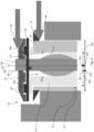
- Fig. 3 shows a schematic cross-sectional view of a bushing assembly according to one embodiment of the invention arranged in the zero-eccentric position;
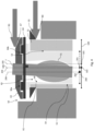
- Fig. 4 shows a schematic cross-sectional view of a bushing assembly according to one embodiment of the invention arranged in the maximum eccentric position.
Detailed Description
-
Fig. 1 shows a section of a gyratory crusher 1, having a frame 2 defining the exterior of the gyratory crusher 1. A crushing shell (not shown), also referred to as the liner, is attached to the inner surface of the frame 2. A bushing housing 4 is located in a lower portion of the frame 2 and attached to the frame 2. The bushing housing 4 has a cylindrical shaped cavity suitable for accommodating a bushing assembly 50. The bushing assembly comprising a first bushing 51 located in the cavity of the bushing housing 4. The first bushing 51 has a flange 52 located in the upper portion of the first bushing. The flange 52 has top surface for supporting the second bushing 61. The second bushing 61 has a flange 62 configured to support the first (upper) gear ring 63 and the second (lower) gear ring 64.
-
The second gear ring 64 is positioned between the second bushing 61 and the first gear ring 63 and provides a flexible connection between the first gear ring 63 and the second bushing 61 allowing them to have angular and/or axial misalignment. The flexible properties are achieved by configuring the first gear ring 63, the second gear ring 64 and the second bushing 61 as an Oldham coupling. The second bushing 61 comprises oppositely arranged grooves on its upper surface and the second gear ring 64 comprises matching tongues on its lower surface which together form the flexible joints 90a and 90b allowing for misalignment in a first direction.
-
The second gear ring 64 also comprises tongues on its upper surface. These tongues are placed with a 90° offset compared to the ones on the lower surface. The first gear ring 63 comprises matching grooves on its lower surface which together with the tongues form the flexible joints 91a and 91b allowing for misalignment in a direction perpendicular to the first direction. Together the flexible joints 90 and 91 allow for misalignment in two dimensions between the second bushing 61 and the first gear ring 63.
-
An elongated shaft 7 is arranged in the bushing assembly 50. A crushing head 8 is mounted upon the elongated shaft 7. A crushing shell (not shown) is mounted on the crushing head 8.
-
The crushing shell mounted on the frame is stationary and spaced from the crushing shell mounted on the crushing head 8. The first and second crushing shells define together a crushing gap through which the material to be crushed is passed.
-
Turning now to Fig. 2 showing a cross sectional view of a bottom portion of a crusher similar to that depicted in Fig. 1. It can be seen that the crusher comprises a bushing assembly 50 having a spherical bearing arrangement 60, provided by a conical sleeve provided onto an outer surface of the shaft 7 and a convex inner surface 65 of the second bushing 61.
-
Fig. 3 shows a schematic cross-sectional view showing a simplified and exaggerated view of the bushing assembly 50. In both Fig. 2 and Fig. 3, the bushing assembly 50 is arranged in a zero-eccentricity position. The first bushing 51 has a cylindrical outer surface with a flange 52 protruding radially from an upper portion of the first bushing 51. An upper surface of the flange 52 is configured for supporting the second bushing 61. The first bushing 51 has a cavity 53 located off-center in the first bushing 51. The cavity 53 has a substantially cylindrical inner surface 54 for accommodating a second bushing 61. The second bushing 61 has a cylindrical outer surface mutually corresponding to the inner surface 54 of the first bushing 51. During intended use of the bushing assembly, there is a small gap between the bushings for accommodating a lubricant and allowing relative rotation of the bushings. The second bushing 61 has a cavity 65 located at an off-center position in the second bushing 61, said cavity 65 suitable for accommodating a shaft 7.
-
The solid line 100 shows the diameter (width) of the first bushing 51. The center axis 105 is marked on the solid line 100 by point 101. An eccentric axis 106 shows the center of the cavity 53 in the first bushing. The eccentric axis 106 is marked on the solid line 100 by point 102.
-
The dotted line 200 shows the diameter (width) of the second bushing 61. The second center axis 205 of the second bushing is marked on the line 200 by point 201. A second eccentric axis 206 is marked on the dotted line 200 by point 202. The cavity 65 is defined centrally around the eccentric axis 206.
-
In this embodiment of the invention, the second center axis 205 is substantially coaxial with the first eccentric axis 106.
-
The first bushing 51 and second bushing 61 are configured to rotate around their respective center axis' (101, 201). When the angular velocity of the first bushing 51 and the second bushing 61 are equal the relationship between the center axis's (101, 201) and the eccentric axis' (106, 206) are constant. In the embodiment shown in Fig. 3, the first eccentric axis (102) and second center axis (205) will rotate around the first center axis (105) in a circular path. This configuration shown in Fig. 3 is referred to as the zero eccentric position.
-
When the first bushing 51 and second bushing 61 are rotated with different relative angular velocities, the relationship between the center axis's (101, 201) and the eccentric axis' (106, 206) change. This is shown in Fig. 4 which shows a max eccentricity position. The max eccentricity position is achieved when the second bushing 61 is rotated with 180° compared to the zero eccentric position.
-
The eccentricity may also achieve intermediate positions if the bushing is rotated with between 1° and 179° with respect from the zero eccentric position.
-
Typically, an upper portion of the shaft 7 is maintained in a constant position (typically on the center axis 101) by means of a spider (not shown). As the lower portion of the shaft is positioned with an offset to the center axis 101, the shaft is inclined with respect to the center axis 101.
-
In both embodiments shown in Fig. 3 and Fig. 4, the bushing assembly 50 is configured such that the second center axis 205 is substantially coaxial with the first eccentric axis 106. This provides a bushing assembly where the eccentricity of the first bushing 51 and second bushing 61 cancel out each other in the zero eccentric position. Thus, the shaft 7 is maintained at the same position while rotating the first bushing 51 and second bushing 61 at same angular velocities in the zero eccentric position.
-
In the embodiments shown in Fig. 3 and Fig 4, the bushing assembly is configured with a spherical bearing arrangement 60 composed of an inner surface of the second cavity 65 and an outer surface of the shaft 7. Particularly, this is achieved by the second cavity 65 having a concave inner surface 66. Alternatively, the second cavity 65 may comprises a liner providing the concave inner surface. The concave inner surface 66 in combination with a shaft 7 having a mutually corresponding convex outer surface 71 allows the shaft to be easily inclined with respect to the eccentric axis 206. Typically, the inclination of the shaft would be from 0° to 3° or from 0° to 5°.
-
The first bushing 51 comprises drive engaging means in the form of a toothed surface 55 for engaging with a corresponding surface on a drive pinion 80. The rotation of the second bushing 61 is achieved by rotating the first gear ring 63 which comprises drive engaging means in the form of a toothed surface 67. A second drive pinion 81 is configured to engage with the toothed surface 67. The second gear ring 64 is configured as a flexible coupling and provides rotational motion from the first gear ring 63 to the second bushing 61. The flexible connection, allowing for misalignment between the second bushing 61 and the first gear ring 63 is achieved by the flexible joints 91a and 91b and the flexible joints 90a, 90b which are not visible on Fig. 3 and Fig. 4.
-
The toothed surface 67 of the upper gear ring 63 may be located on a surface facing substantially upwards or downwards of the gear ring 63. In Fig. 3 and Fig. 4, the toothed surface is shown on a surface facing substantially upwards, but it may be configured on a surface facing substantially downwards as the toothed surface 55 on the first bushing 51.
-
During intended operation of the crusher, the eccentricity is set by initially rotating the second bushing 61 relative to the first bushing 51. Once the desired eccentric is achieved, the first bushing 51 and second bushing 61 are rotated with a relative angular velocity of 0. This provides an eccentric movement of the shaft and mantle at a constant eccentricity.
-
To adjust the eccentricity, the relative angular velocity of the first bushing 51 and second bushing 61 is changed to a value different from 0.