EP4534189A1 - Mixing apparatus, and method for producing mixed solution - Google Patents
Mixing apparatus, and method for producing mixed solution Download PDFInfo
- Publication number
- EP4534189A1 EP4534189A1 EP23811415.1A EP23811415A EP4534189A1 EP 4534189 A1 EP4534189 A1 EP 4534189A1 EP 23811415 A EP23811415 A EP 23811415A EP 4534189 A1 EP4534189 A1 EP 4534189A1
- Authority
- EP
- European Patent Office
- Prior art keywords
- mixing tank
- mixed solution
- liquid level
- mixing
- materials
- Prior art date
- Legal status (The legal status is an assumption and is not a legal conclusion. Google has not performed a legal analysis and makes no representation as to the accuracy of the status listed.)
- Pending
Links
Images



Classifications
-
- B—PERFORMING OPERATIONS; TRANSPORTING
- B01—PHYSICAL OR CHEMICAL PROCESSES OR APPARATUS IN GENERAL
- B01F—MIXING, e.g. DISSOLVING, EMULSIFYING OR DISPERSING
- B01F35/00—Accessories for mixers; Auxiliary operations or auxiliary devices; Parts or details of general application
- B01F35/80—Forming a predetermined ratio of the substances to be mixed
- B01F35/88—Forming a predetermined ratio of the substances to be mixed by feeding the materials batchwise
- B01F35/883—Forming a predetermined ratio of the substances to be mixed by feeding the materials batchwise using flow rate controls for feeding the substances
-
- B—PERFORMING OPERATIONS; TRANSPORTING
- B01—PHYSICAL OR CHEMICAL PROCESSES OR APPARATUS IN GENERAL
- B01F—MIXING, e.g. DISSOLVING, EMULSIFYING OR DISPERSING
- B01F35/00—Accessories for mixers; Auxiliary operations or auxiliary devices; Parts or details of general application
- B01F35/20—Measuring; Control or regulation
- B01F35/22—Control or regulation
- B01F35/221—Control or regulation of operational parameters, e.g. level of material in the mixer, temperature or pressure
- B01F35/2212—Level of the material in the mixer
-
- B—PERFORMING OPERATIONS; TRANSPORTING
- B01—PHYSICAL OR CHEMICAL PROCESSES OR APPARATUS IN GENERAL
- B01F—MIXING, e.g. DISSOLVING, EMULSIFYING OR DISPERSING
- B01F23/00—Mixing according to the phases to be mixed, e.g. dispersing or emulsifying
- B01F23/40—Mixing liquids with liquids; Emulsifying
- B01F23/43—Mixing liquids with liquids; Emulsifying using driven stirrers
-
- B—PERFORMING OPERATIONS; TRANSPORTING
- B01—PHYSICAL OR CHEMICAL PROCESSES OR APPARATUS IN GENERAL
- B01F—MIXING, e.g. DISSOLVING, EMULSIFYING OR DISPERSING
- B01F25/00—Flow mixers; Mixers for falling materials, e.g. solid particles
- B01F25/50—Circulation mixers, e.g. wherein at least part of the mixture is discharged from and reintroduced into a receptacle
-
- B—PERFORMING OPERATIONS; TRANSPORTING
- B01—PHYSICAL OR CHEMICAL PROCESSES OR APPARATUS IN GENERAL
- B01F—MIXING, e.g. DISSOLVING, EMULSIFYING OR DISPERSING
- B01F27/00—Mixers with rotary stirring devices in fixed receptacles; Kneaders
- B01F27/05—Stirrers
- B01F27/07—Stirrers characterised by their mounting on the shaft
- B01F27/072—Stirrers characterised by their mounting on the shaft characterised by the disposition of the stirrers with respect to the rotating axis
- B01F27/0724—Stirrers characterised by their mounting on the shaft characterised by the disposition of the stirrers with respect to the rotating axis directly mounted on the rotating axis
-
- B—PERFORMING OPERATIONS; TRANSPORTING
- B01—PHYSICAL OR CHEMICAL PROCESSES OR APPARATUS IN GENERAL
- B01F—MIXING, e.g. DISSOLVING, EMULSIFYING OR DISPERSING
- B01F27/00—Mixers with rotary stirring devices in fixed receptacles; Kneaders
- B01F27/05—Stirrers
- B01F27/09—Stirrers characterised by the mounting of the stirrers with respect to the receptacle
-
- B—PERFORMING OPERATIONS; TRANSPORTING
- B01—PHYSICAL OR CHEMICAL PROCESSES OR APPARATUS IN GENERAL
- B01F—MIXING, e.g. DISSOLVING, EMULSIFYING OR DISPERSING
- B01F27/00—Mixers with rotary stirring devices in fixed receptacles; Kneaders
- B01F27/05—Stirrers
- B01F27/11—Stirrers characterised by the configuration of the stirrers
- B01F27/19—Stirrers with two or more mixing elements mounted in sequence on the same axis
- B01F27/191—Stirrers with two or more mixing elements mounted in sequence on the same axis with similar elements
-
- B—PERFORMING OPERATIONS; TRANSPORTING
- B01—PHYSICAL OR CHEMICAL PROCESSES OR APPARATUS IN GENERAL
- B01F—MIXING, e.g. DISSOLVING, EMULSIFYING OR DISPERSING
- B01F27/00—Mixers with rotary stirring devices in fixed receptacles; Kneaders
- B01F27/80—Mixers with rotary stirring devices in fixed receptacles; Kneaders with stirrers rotating about a substantially vertical axis
- B01F27/90—Mixers with rotary stirring devices in fixed receptacles; Kneaders with stirrers rotating about a substantially vertical axis with paddles or arms
-
- B—PERFORMING OPERATIONS; TRANSPORTING
- B01—PHYSICAL OR CHEMICAL PROCESSES OR APPARATUS IN GENERAL
- B01F—MIXING, e.g. DISSOLVING, EMULSIFYING OR DISPERSING
- B01F27/00—Mixers with rotary stirring devices in fixed receptacles; Kneaders
- B01F27/80—Mixers with rotary stirring devices in fixed receptacles; Kneaders with stirrers rotating about a substantially vertical axis
- B01F27/91—Mixers with rotary stirring devices in fixed receptacles; Kneaders with stirrers rotating about a substantially vertical axis with propellers
-
- B—PERFORMING OPERATIONS; TRANSPORTING
- B01—PHYSICAL OR CHEMICAL PROCESSES OR APPARATUS IN GENERAL
- B01F—MIXING, e.g. DISSOLVING, EMULSIFYING OR DISPERSING
- B01F35/00—Accessories for mixers; Auxiliary operations or auxiliary devices; Parts or details of general application
- B01F35/20—Measuring; Control or regulation
- B01F35/22—Control or regulation
- B01F35/221—Control or regulation of operational parameters, e.g. level of material in the mixer, temperature or pressure
- B01F35/2211—Amount of delivered fluid during a period
-
- B—PERFORMING OPERATIONS; TRANSPORTING
- B01—PHYSICAL OR CHEMICAL PROCESSES OR APPARATUS IN GENERAL
- B01F—MIXING, e.g. DISSOLVING, EMULSIFYING OR DISPERSING
- B01F35/00—Accessories for mixers; Auxiliary operations or auxiliary devices; Parts or details of general application
- B01F35/71—Feed mechanisms
-
- B—PERFORMING OPERATIONS; TRANSPORTING
- B01—PHYSICAL OR CHEMICAL PROCESSES OR APPARATUS IN GENERAL
- B01F—MIXING, e.g. DISSOLVING, EMULSIFYING OR DISPERSING
- B01F35/00—Accessories for mixers; Auxiliary operations or auxiliary devices; Parts or details of general application
- B01F35/71—Feed mechanisms
- B01F35/712—Feed mechanisms for feeding fluids
-
- B—PERFORMING OPERATIONS; TRANSPORTING
- B01—PHYSICAL OR CHEMICAL PROCESSES OR APPARATUS IN GENERAL
- B01F—MIXING, e.g. DISSOLVING, EMULSIFYING OR DISPERSING
- B01F35/00—Accessories for mixers; Auxiliary operations or auxiliary devices; Parts or details of general application
- B01F35/75—Discharge mechanisms
-
- B—PERFORMING OPERATIONS; TRANSPORTING
- B01—PHYSICAL OR CHEMICAL PROCESSES OR APPARATUS IN GENERAL
- B01F—MIXING, e.g. DISSOLVING, EMULSIFYING OR DISPERSING
- B01F2101/00—Mixing characterised by the nature of the mixed materials or by the application field
- B01F2101/2805—Mixing plastics, polymer material ingredients, monomers or oligomers
Definitions
- the present invention relates to a mixing apparatus and a method for producing a mixed solution.
- Patent Literature 1 discloses a method for producing a polyacrylic acid (salt) based water-absorbent resin having an excellent whiteness degree.
- the production method according to Patent Literature 1 includes a process of storing or producing acrylic acid, a process of mixing and/or neutralizing acrylic acid containing a polymerization inhibitor, water, a cross-linking agent, and a basic composition to prepare a monomer aqueous solution, a process of polymerizing the monomer aqueous solution, a process of drying an obtained hydrous gel-like crosslinked polymer, a process of performing a surface crosslinking, and the like.
- an apparatus 2 or an apparatus 26 that includes a neutralization tank 3, a pump 4, a heat exchanger 6, a line mixer 8, a polymerization machine 10, and piping connecting these.
- a neutralization tank 3 In the apparatus 2, an outlet 24 of the neutralization tank 3, the pump 4, the heat exchanger 6 and an inlet 22 of the neutralization tank 3 are connected in this order to form a circulation loop.
- a pipe branched off from the circulation loop between the heat exchanger 6 and the inlet 22 of the neutralization tank 3 is connected to the downstream line mixer 8 and the polymerization machine 10.
- Patent Literature 1 WO 2011/040575
- a liquid containing acrylic acid and a basic aqueous solution are continuously supplied to a neutralization system constituting the circulation loop.
- this mixed solution is stirred inside the neutralization tank 3 and is circulated through the circulation loop, a part of it is also continuously supplied to the polymerization machine 10, and the circulation of the mixed solution and the supply to the polymerization machine simultaneously proceed.
- neutralization heat is generated due to the neutralization reaction, by adjusting the temperature of the mixed solution by the heat exchanger 6, the temperature of the mixed solution in the circulation loop can be maintained within a desired range, and a predetermined neutralization rate can be achieved.
- the above-described points are not limited to a case of producing a water-absorbent resin by performing a preparation of a mixed solution through neutralization of an acidic substance with a basic substance, but also similarly apply to a case of preparing a mixed solution such that two or more kinds of materials are mixed to a desired degree, or to a case of producing a product other than a water-absorbent resin by preparing a mixed solution.
- a mixing apparatus includes a material supply line, a mixing tank, a stirring device, and a transportation line.
- the material supply line supplies two or more kinds of materials including a liquid.
- the mixing tank accommodates the two or more kinds of materials that have been supplied through the material supply line.
- the stirring device stirs a mixed solution of the two or more kinds of materials inside the mixing tank.
- the transportation line is connected to the mixing tank and transports the mixed solution inside the mixing tank to an outside of the mixing tank.
- the mixing apparatus is configured to maintain a liquid level height of the mixed solution inside the mixing tank at a level falling within a predetermined range by controlling at least one of a supply amount of the two or more kinds of materials to be supplied into the mixing tank through the material supply line and a transportation amount of the mixed solution to be transported to the outside of the mixing tank through the transportation line.
- At least one of the supply amount of the materials including the liquid to the mixing tank and the transportation amount of the mixed solution to be transported from the mixing tank to the outside is controlled so as to maintain the liquid level height of the mixed solution inside the mixing tank at a level falling within a predetermined range.
- the stirring device includes: a shaft portion rotatable inside the mixing tank, and one or a plurality of stirring blades joined to the shaft portion, the stirring blade rotating inside the mixing tank in association with rotation of the shaft portion.
- H1 a height along a vertical direction from a lowermost position of a bottom portion of the mixing tank to an upper end of the stirring blade at an uppermost position
- the mixing apparatus is configured to maintain the liquid level height such that the liquid level height becomes equal to or less than 1.21 H1 and equal to or more than a height of a lower end of the stirring blade at the uppermost position.
- an upper limit of the liquid level height is set with the height of the upper end of the stirring blade at the uppermost position as a reference
- a lower limit of the liquid level height is set with the height of the lower end of the stirring blade at the uppermost position as a reference.
- the transportation line is connected to a lower discharge port formed in a lower portion of the mixing tank, and the transportation line has a return line that returns the mixed solution discharged from the lower discharge port back into the mixing tank from an upper side of the mixing tank.
- the mixed solution discharged from the lower discharge port of the mixing tank is returned from the upper side of the mixing tank back to the mixing tank through the return line. This increases the stirring effect of the entire mixed solution and makes the mixed solution more homogeneous.
- the mixing apparatus is configured to maintain the liquid level height of the mixed solution inside the mixing tank at a level falling within a predetermined range by controlling at least one of the supply amount of the two or more kinds of materials to be supplied to the mixing tank through the material supply line, a return amount of the mixed solution to be returned to the mixing tank through the return line, and the transportation amount of the mixed solution to be transported from the mixing tank to another apparatus through the transportation line.
- the material supply line has a first opening for discharging the two or more kinds of materials into the mixing tank on the upper side of the mixing tank
- the return line has a second opening for discharging the mixed solution into the mixing tank on the upper side of the mixing tank
- the mixing apparatus is configured such that the two or more kinds of materials are discharged through the first opening onto a liquid level of the mixed solution present in at least one of the first virtual region and the second virtual region, the mixed solution that have been returned through the second opening is discharged onto a liquid level of the mixed solution present in at least one of the fourth virtual region and the fifth virtual region, and discharge of the two or more kinds of materials through the first opening and discharge
- the mixing apparatus of the fifth aspect at the liquid level of the mixing tank, the region into which the two or more kinds of materials are discharged and the region into which the returned mixed solution is discharged are sufficiently separated. This makes it easier for the discharged materials to be mixed with one another at and near the liquid level of the mixed solution, and thus, generation of a local bias in the concentration distribution due to the supply of the materials is suppressed.
- a production method of a mixed solution according to a sixth aspect of the present invention includes the following (1) to (4):
- the following describes a mixing apparatus according to one embodiment of the present invention and a method for producing a mixed solution using this mixing apparatus with reference to the drawings.
- a mixing apparatus according to one embodiment of the present invention and a method for producing a mixed solution using this mixing apparatus with reference to the drawings.
- the mixed solution produced by the mixing apparatus becomes a water-absorbent resin through a polymerization process and a drying process.
- Fig. 1 is an overall configuration diagram of a mixing apparatus 100 according to this embodiment.
- the mixing apparatus 100 is an apparatus for producing a mixed solution CL containing two or more kinds of materials including a liquid and for continuously sending this to a next process.
- the mixing apparatus 100 includes a mixing tank 1 for accommodating the mixed solution CL, a stirring device 2 for stirring the mixed solution CL inside the mixing tank 1, a material supply line 3 for supplying the above-described materials into the mixing tank 1, and a transportation line 4 for transporting the mixed solution CL to the outside of the mixing tank 1.
- the mixing apparatus 100 includes a control unit 7 that controls a production process of the mixed solution CL by controlling operations of the stirring device 2, the material supply line 3, and the transportation line 4. The following describes each element of the mixing apparatus 100.
- the mixing tank 1 is a container an inner wall surface of which is constituted of a material that is resistant to the mixed solution CL, and in this embodiment, has a substantially cylindrical shape that is circular in a top surface view.
- the mixing tank 1 is arranged such that its central axis A1 extends along the vertical direction and has a top surface portion 10 facing upward, a bottom surface portion 11 facing downward, and a body portion 12 extending between the top surface portion 10 and the bottom surface portion 11.
- the mixing tank 1 is connected to the material supply line 3 via the top surface portion 10. As a result, the materials of the mixed solution CL are supplied to the space inside the mixing tank 1 through the material supply line 3.
- the bottom surface portion 11 is formed with a lower discharge port 110 that is an opening for discharging the mixed solution CL to the outside of the mixing tank 1, and the mixing tank 1 is connected to the transportation line 4 via the lower discharge port 110.
- the lower discharge port 110 is opened, and thus, the mixed solution CL continuously flows out into the transportation line 4.
- the mixing tank 1 is further connected to a return line 4b via the top surface portion 10.
- the return line 4b is a branching path branching from the transportation line 4.
- the mixed solution CL to be returned into the mixing tank 1 through the return line 4b is referred to as "a mixed solution CL1" for distinction, in some cases.
- the stirring device 2 has a shaft portion 20 that can rotate inside the mixing tank 1 and a stirring blade 21 that is joined to the shaft portion 20 and is entirely housed inside the mixing tank 1.
- the shaft portion 20 is aligned so as to extend along the central axis A1 of the mixing tank 1 and can be driven by a driving source such as a motor (not illustrated) to rotate around the central axis A1 at a predetermined rotation speed.
- the stirring blade 21 extends radially outward with the shaft portion 20 as a reference and rotates inside the mixing tank 1 around the shaft portion 20 as the shaft portion 20 rotates. This causes a convective flow in the mixed solution CL, and the mixed solution CL is stirred.
- the rotation speed of the shaft portion 20 is controlled by the control unit 7.
- the stirring blade 21 can be constituted of, for example, one or a plurality of paddles, although it is not limited to this.
- the paddle has a generally plate-like external shape, and one end is joined to the shaft portion 20 such that its widest surface (a main surface) is inclined with respect to the horizontal direction.
- An inclination angle of the paddle main surface with respect to the horizontal direction is not particularly limited and may be larger than 0 degrees and equal to or less than 90 degrees and may change midway along the main surface.
- the main surface of the paddle may include a flat surface or a curved surface.
- the paddle may include an auxiliary fin.
- the paddles can be each arranged such that they have equal intervals around the shaft portion 20 as a center at a same position in the vertical direction of the shaft portion 20.
- the stirring device 2 may have one stirring blade 21 or may have a plurality of stirring blades 21 arranged at different positions in the vertical direction of the shaft portion 20.
- the stirring device 2 of this embodiment has two stirring blades 21a and 21b each constituted of a plurality of paddles.
- the stirring blade 21a is an uppermost stirring blade arranged at a position closer to the top surface portion 10
- the stirring blade 21b is a lowermost stirring blade arranged at a position closer to the bottom surface portion 11.
- the vertical positions of the stirring blades 21a and 21b are secured during the production process.
- the lowermost position of the stirring blade 21a in the vertical direction is referred to as a lower end of the stirring blade 21a
- the uppermost position of the stirring blade 21a in the vertical direction is referred to as an upper end of the stirring blade 21a.
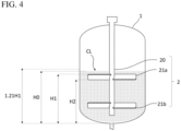
- a height along the vertical direction from the lowermost position of the bottom surface portion 11 of the mixing tank 1 up to the upper end of the stirring blade 21a is H1
- a height from the same position up to the lower end of the stirring blade 21a is H2 (see Fig. 4 ).
- the material supply line 3 is a supply path for supplying materials of the mixed solution CL into the mixing tank 1, and in this embodiment, is a generic term for three supply lines 3a to 3c.
- the supply lines 3a to 3c are each connected to the mixing tank 1.
- a material mainly made of an acidic substance is supplied into the mixing tank 1 from the supply line 3a
- a material mainly made of a basic substance is supplied from the supply line 3b
- water is supplied from the supply line 3c.
- Control valves 30a to 30c are attached to the supply lines 3a to 3c, respectively, and a supply amount of each material can be controlled by the control unit 7 controlling opening and closing amounts of these control valves 30a to 30c.
- the control valves 30a to 30c may be configured to measure flow rates of the materials in the supply lines 3a to 3c and may be configured to output this to the control unit 7.
- an aqueous solution containing an ethylenically unsaturated monomer is supplied as an acidic substance from the supply line 3a, and an aqueous solution containing a neutralizing agent for the ethylenically unsaturated monomer is supplied as a basic substance from the supply line 3b, respectively.
- Each of the materials to be supplied from the supply lines 3a to 3c may contain other additive agents.
- Examples of a water-soluble ethylenically unsaturated monomer includes (meth)acrylic acid and its salts, 2-(meth) acrylamido-2-methylpropanesulfonic acid and its salts, (meth)acrylamide, N,N-dimethyl(meth)acrylamide, 2-hydroxyethyl(meth)acrylate, N-methylol(meth)acrylamide, polyethylene glycol mono(meth)acrylate, N,N-diethylaminoethyl(meth)acrylate, N,N-diethylaminopropyl(meth)acrylate, diethylaminopropyl(meth)acrylamide, and the like.
- Examples of the neutralizing agent includes alkali metal salts such as sodium hydroxide, sodium carbonate, sodium bi carbonate, potassium hydroxide, and potassium carbonate, ammonia, and the like.
- the material supply line 3 has a first opening for discharging the materials into the mixing tank 1 on the upper side of the mixing tank 1.
- openings 300a to 300c formed in the supply lines 3a to 3c correspond to the first opening.
- One or a plurality of respective openings 300a to 300c may be formed in each of the supply lines 3a to 3c, respectively.
- the number of openings 300a to 300c may be the same or different for the supply lines 3a to 3c.
- the transportation line 4 is a transportation path for transporting the mixed solution CL inside the mixing tank 1 to the outside of the mixing tank 1 via the lower discharge port 110 and has a next process line 4a for transporting the mixed solution CL to another apparatus and a return line 4b for returning the mixed solution CL1 back into the mixing tank.
- the transportation line 4 has a pump 5 and control valves 40a and 40b, and a transportation amount of the mixed solution CL through the next process line 4a is controlled by the control unit 7 controlling a transfer amount of the pump 5 and opening and closing amounts of the control valve 40a.
- a return amount of the mixed solution CL1 through the return line 4b is controlled by the control unit 7 controlling the transfer amount of the pump 5 and opening and closing amounts of the control valve 40b.
- the control valves 40a and 40b may be configured to measure the flow rate of the mixed solution CL in the next process line 4a and the flow rate of the mixed solution CL1 in the return line 4b, respectively, and to output these flow rates to the control unit 7.
- the pump 5 may be omitted.
- the next process line 4a is connected to another apparatus (not illustrated) other than the mixing apparatus 100, and a next process of the production process is performed in another apparatus.
- the mixed solution CL is transported to another apparatus through the next process line 4a.
- the mixed solution CL once transported to the next process line 4a is not returned to the mixing apparatus 100.
- the return line 4b has a heat exchanger 6.
- the heat exchanger 6 is configured to perform temperature adjustment of the mixed solution CL1 transported inside the return line 4b, and the operation of it may be controlled by the control unit 7.
- the heat exchanger 6 is configured to remove at least a part of neutralization heat generated in the mixed solution CL1.
- the heat exchanger 6 may be omitted.
- the return line 4b further has a second opening for discharging the mixed solution CL1 that is returned into the mixing tank 1 on the upper side of the mixing tank 1.
- One second opening may be formed in the return line 4b or a plurality of second openings may be formed in the return line 4b, and in this embodiment, an opening 400 formed in the return line 4b corresponds to the second opening.
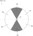
- the supply lines 3a to 3c and the return line 4b are preferably configured such that the material discharged into the mixing tank 1 through the openings 300a to 300c and the mixed solution CL1 discharged into the mixing tank 1 through the opening 400 are sufficiently separated from one another. More specifically, as illustrated in Fig. 2A , a transverse cross-section of the body portion 12 is divided into six regions at 60 degrees each with the central axis A1 as a reference, and these divided regions are assumed to be a first virtual region R1 to a sixth virtual region R6 adjacent to each other in clockwise order.
- the materials are each discharged through the openings 300a to 300c onto a liquid level of the mixed solution CL present in at least one of the first virtual region R1 and the second virtual region R2, the mixed solution CL1 is discharged through the opening 400 onto a liquid level of the mixed solution CL present in at least one of the fourth virtual region R4 and the fifth virtual region R5, and the materials or the mixed solution CL1 is not discharged onto a liquid level of the mixed solution CL present in the third virtual region R3 and the sixth virtual region R6 (a half-tone dot meshing regions in Fig. 2A ).
- the materials are each discharged through the openings 300a to 300c preferably onto the liquid level present in at least one of the eighth virtual region R8 and the ninth virtual region R9, and more preferably onto the liquid level present in the ninth virtual region R9.
- the seventh to ninth virtual regions R7 to R9 are virtual regions divided such that their lengths in the radially outward direction of the central axis A1 are equal to one another (see Fig. 2B ).
- the mixed solution CL1 is discharged through the opening 400 preferably onto the liquid level present in at least one of the eighth virtual region R8 and the ninth virtual region R9, and more preferably onto the liquid level present in the ninth virtual region R9. In this case, it is preferable that no mixed solution CL1 is discharged into the seventh virtual region R7.
- the precipitate generation suggests that there is a bias in the neutralization degree of the mixed solution CL (namely, there is variation in quality), and when such mixed solution CL is sent to the next process, it will become a factor that increases the variation in quality of a final product. For this reason, it is preferable to suppress the generation of the precipitate during the production process.
- the inventors have confirmed through experiments that the above-described precipitate is generated when the neutralizing agent aqueous solution and the mixed solution CL1 are discharged onto the liquid level of the mixed solution CL present in one virtual region or two adjacent virtual regions. Specifically, when the neutralizing agent aqueous solution, water, and the mixed solution CL1 were discharged onto the liquid level of the mixed solution CL present in the fourth virtual region and the fifth virtual region R5 in Fig.
- the region into which the neutralizing agent aqueous solution is discharged and the region into which the ethylenically unsaturated monomer aqueous solution is discharged are positioned oppositely with one another with respect to the central axis A1, and thus it becomes relatively late until both of them start the neutralization reaction after reaching the liquid level, resulting in causing the localized bias in the neutralization degree.
- the variation in the quality of the mixed solution is suppressed by setting the height of the liquid level of the mixed solution CL1 in the mixing tank at a level falling within a predetermined range, and additionally, the variation in the quality of the mixed solution CL1 is further suppressed by sufficiently separating the discharge region of the materials and the discharge region of the mixed solution CL1 with the above-described arrangement relationship, even when the height of the liquid level of the mixed solution CL1 is not set at a level falling within a predetermined range and it is a mixing apparatus that has only the above-described arrangement relationship, it is possible to suppress the variation in the quality of the mixed solution CL1.
- the control unit 7 controls the operation of each element of the mixing apparatus 100 so as to automatically execute the production process.
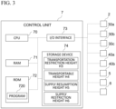
- Fig. 3 is a block diagram illustrating an electrical configuration of the control unit 7.
- the control unit 7 is a general-purpose computer as hardware, and includes a CPU 70, a RAM 71, a ROM 72, an I/O interface 73, and a non-volatile rewritable storage device 74, and these elements are connected to one another by a bus line.
- the I/O interface 73 is a communication device for communicating with external devices such as the stirring device 2, the control valves 30a to 30c, the control valves 40a and 40b, the pump 5 and the heat exchanger 6, and so on.
- a program 720 for controlling the operation of each element of the mixing apparatus 100 is stored in the ROM 72.
- the control unit 7 performs the control described below.
- the storage device 74 is constituted of a hard disk, a flash memory, and the like.
- a storage location of the program 720 may be the storage device 74 instead of the ROM 72.
- the RAM 71 and the storage device 74 are appropriately used for a computation of the CPU 70.
- the control unit 7 supplies each material into the mixing tank 1 at a ratio to bring the mixed solution CL to a predetermined neutralization degree by adjusting the opening and closing amounts of the control valves 30a to 30c of the supply lines 3a to 3c, respectively.
- the control unit 7 transports the required amount of the mixed solution CL to the next process line 4a by adjusting each of the opening and closing amounts of the control valves 40a and 40b of the transportation line 4 and the transfer amount of the pump 5, and also transports the remaining mixed solution CL1 to the return line 4b so as to return it to the mixing tank 1.
- a supply amount V1 that is a flow rate of the materials through the supply lines 3a to 3c, a transportation amount V2 that is a flow rate of the mixed solution CL through the next process line 4a, and a return amount V3 that is a flow rate of the mixed solution CL1 through the return line 4b are adjusted so as to maintain a liquid level height H0 of the mixed solution CL inside the mixing tank 1 at a level falling within a predetermined range.
- control unit 7 performs the control for maintaining the liquid level height H0 at a level falling within a predetermined range by controlling V2, which is an irreversible outflow amount to the outside of the mixing tank 1 relative to (V1 + V3), which is an inflow amount into the mixing tank 1, or by controlling (V1 + V3) relative to V2.
- the liquid level height H0 of the mixed solution CL is the height along the vertical direction from the lowermost position of the bottom surface portion 11 up to the liquid level of the mixed solution CL.
- the lowermost position of the bottom surface portion 11 refers to the lowermost position in the vertical direction on the inner wall surface of the bottom surface portion 11, and in this embodiment, the peripheral edge portion of the lower discharge port 110 corresponds to the lowermost position of the bottom surface portion 11.
- the control unit 7 controls at least one of the above-described supply amount V1, transportation amount V2, and return amount V3 such that the liquid level height H0 becomes equal to or more than H2 and equal to or less than 1.21 H1 during the production process being performed.
- a transportation restriction height H3, a transportable height H4, a supply resumption height H5, and a supply restriction height H6 are each predetermined and stored in the storage device 74. These parameters are determined to satisfy, for example, H2 ⁇ H3 ⁇ H4 ⁇ H5 ⁇ H6 ⁇ 1.21 H1 although they are not limited to this. It is preferable that the position where the height is H2 and the position where the height is 1.21 H1 are both positions in the body portion 12 of the mixing tank 1.
- This precipitate is the crystal of the above-described neutralizing agent and is believed to have been generated due to a local increase of the neutralization degree in the proximity of the neutralizing agent aqueous solution that was discharged from the opening 300b of the supply line 3b and reached the mixed solution CL.
- the deviation between the stirring blade 21a and the liquid level is further considered.
- Fig. 5 is a flowchart illustrating a flow of the control of the control unit 7.
- step S1 the ethylenically unsaturated monomer aqueous solution, the neutralizing agent aqueous solution, and water are continuously supplied to the empty mixing tank 1 from the material supply line 3.
- the supply amount V1 of the materials at this time can be a predetermined specified amount.
- the control unit 7 rotates the stirring device 2 at a predetermined rotation speed and controls the respective opening amounts of the control valves 30a to 30c such that each material is contained in a predetermined mass ratio in the supply amount V1.
- the control unit 7 preliminarily controls so as to stop the pump 5 and close the control valves 40a and 40b.
- Step S1 continues until the liquid level height H0 of the mixed solution CL reaches the transportable height H4.
- the time for the liquid level height H0 to reach the transportable height H4 is preliminarily determined based on the volume of the mixing tank 1 and the supply amount V1 in step S1 and is stored in the RAM 71 or the storage device 74.
- the control unit 7 determines this in step S1 and stores it in the RAM 71 or the storage device 74.
- step S2 transportation of the mixed solution CL through the next process line 4a starts.
- the control unit 7 drives the pump 5, opens the control valve 40a, and performs the control so as to transport at least a part of the mixed solution CL discharged from the mixing tank 1 to the next process line 4a.
- the transportation amount V2 at this time can be a predetermined specified amount.
- step S3 the return of the mixed solution CL1 through the return line 4b starts.
- the control unit 7 opens the control valve 40b and performs the control such that the mixed solution CL that has not been transported to the next process line 4a is returned into the mixing tank 1 as the mixed solution CL1.
- the return amount V3 at this time can be a predetermined specified amount.
- step S4 the control unit 7 calculates the current liquid level height H0 of the mixed solution CL based on the supply amount V1 in step S1, the transportation amount V2 in step S2, the return amount V3 in step S3, and the time since the start of each step.
- step S5 the control unit 7 determines whether or not the liquid level height H0 calculated in step S4 is lower than the transportation restriction height H3 (H0 ⁇ H3). When it is determined that the liquid level height H0 is not lower than the transportation restriction height H3 (NO), step S6 is executed. When it is determined that the liquid level height H0 is lower than the transportation restriction height H3 (YES), step S7 is executed.
- step S6 the control unit 7 determines whether or not the liquid level height H0 calculated in step S4 exceeds the supply restriction height H6 (H6 ⁇ H0). When it is determined that the liquid level height H0 does not exceed the supply restriction height H6 (NO), step S4 is executed again. When it is determined that the liquid level height H0 exceeds the supply restriction height H6 (YES), step S10 is executed.
- step S7 the control unit 7 restricts the transportation of the mixed solution CL through the next process line 4a.
- the control unit 7 controls the control valve 40a to close it so as to stop the transportation of the mixed solution CL or to reduce the transportation amount V2 from the current amount.
- the control unit 7 controls the control valve 40a to open it so as to increase the return amount V3 from the current amount by the decrease amount in the transportation amount V2.
- the control unit 7 controls the control valves 30a to 30c to open them so as to increase the supply amount V1 of the materials through the material supply line 3 from the current amount.
- at least one of V1 to V3 is controlled such that an outflow amount V2 is reduced relative to an inflow amount (V1 + V3).
- step S8 is executed.
- step S8 the control unit 7 calculates the current liquid level height H0 of the mixed solution CL and determines whether or not the calculated liquid level height H0 has again reached the transportable height H4 (H4 ⁇ H0).
- step S9 is executed.
- step S7 is executed again. Namely, step S7 is continued until the liquid level height H0 reaches the transportable height H4 or is repeatedly executed while changing at least one of values of V1 to V3.
- step S9 the control unit 7 releases the restriction on the transportation performed in step S7 and controls the opening and closing amounts of the control valves 30a to 30c and the control valves 40a and 40b such that V1 to V3 become specified values. Subsequently, the processes from step S4 onward are repeatedly executed.
- step S10 the control unit 7 restricts at least one of the supply of the materials through the material supply line 3 and the return of the mixed solution CL1 through the return line 4b.
- the control unit 7 controls the control valves 30a to 30c to close them so as to stop the supply of the materials through the material supply line 3 or to reduce the supply amount V1.
- the control unit 7 controls the control valve 40b to close it so as to stop the return of the mixed solution CL1 or to reduce the return amount V3.
- the control unit 7 controls the control valve 40a to open it so as to increase the transportation amount V2 by the decrease amount in the return amount V3.
- at least one of V1 to V3 is controlled such that the inflow amount (V1 + V3) is reduced relative to the outflow amount V2. Subsequently, step S11 is executed.
- step S11 the control unit 7 calculates the current liquid level height H0 of the mixed solution CL and determines whether or not the calculated liquid level height H0 is equal to or less than the supply resumption height H5 (H0 ⁇ H5).
- step S12 is executed.
- step S10 is executed again. Namely, step S10 is continued until the liquid level height H0 becomes equal to or less than the supply resumption height H5 or is repeatedly executed while changing at least one of values of V1 to V3.
- step S12 the control unit 7 releases the restriction on at least one of the supply and the return performed in step S10 and controls the opening and closing amounts of the control valves 30a to 30c and the control valves 40a and 40b such that V1 to V3 become the specified values. Subsequently, the processes from step S4 onwards are repeatedly executed.
- step S1 to step S12 described above being executed in the mixing apparatus 100, it is possible to produce the mixed solution CL in which the bias of the neutralization degree is suppressed.
- the liquid level height H0 of the mixed solution CL inside the mixing tank 1 is maintained at a level falling within a predetermined range.
- the stirring by the stirring device 2 is applied almost constantly to the mixed solution CL inside the mixing tank 1, and unevenness of the stirring is reduced, and thus, variations in the quality of the mixed solution CL such as the neutralization degree and the mixing degree are suppressed.
- an upper limit of the range in which the liquid level height H0 is maintained is set with the upper end of the uppermost stirring blade 21a as a reference.
- the stirring by the stirring blade 21a is applied to the liquid level of the mixed solution CL and its proximity where concentration distribution tends to be biased, and thus, the bias in the concentration distribution and the precipitate generation due to the bias in the concentration distribution can be suppressed. Also, from this point of view, variation in the quality of the mixed solution CL is suppressed.
- the mixing apparatus 100 of the above-described embodiment at the liquid level of the mixed solution CL, the discharge region of the materials and the discharge region of the mixed solution CL1 are separated as far apart as possible along the circumferential direction of the mixing tank 1, namely along the rotation direction of the stirring device 2. With this, the neutralization between the supplied materials is accelerated, the local increase in the neutralization degree is suppressed, and thus, the bias in the concentration distribution and the precipitate generation due to the bias in the concentration distribution can be suppressed. It is also possible to suppress the precipitate generation caused by the supplied neutralizing agent aqueous solution being rapidly cooled by the mixed solution CL1.
Landscapes
- Chemical & Material Sciences (AREA)
- Chemical Kinetics & Catalysis (AREA)
- Physics & Mathematics (AREA)
- Fluid Mechanics (AREA)
- Accessories For Mixers (AREA)
Abstract
Description
- The present invention relates to a mixing apparatus and a method for producing a mixed solution.
-
Patent Literature 1 discloses a method for producing a polyacrylic acid (salt) based water-absorbent resin having an excellent whiteness degree. The production method according toPatent Literature 1 includes a process of storing or producing acrylic acid, a process of mixing and/or neutralizing acrylic acid containing a polymerization inhibitor, water, a cross-linking agent, and a basic composition to prepare a monomer aqueous solution, a process of polymerizing the monomer aqueous solution, a process of drying an obtained hydrous gel-like crosslinked polymer, a process of performing a surface crosslinking, and the like. - In the process of preparing the above-described monomer aqueous solution, an
apparatus 2 or an apparatus 26 is used that includes aneutralization tank 3, apump 4, aheat exchanger 6, a line mixer 8, apolymerization machine 10, and piping connecting these. In theapparatus 2, an outlet 24 of theneutralization tank 3, thepump 4, theheat exchanger 6 and an inlet 22 of theneutralization tank 3 are connected in this order to form a circulation loop. In theapparatus 2, a pipe branched off from the circulation loop between theheat exchanger 6 and the inlet 22 of theneutralization tank 3 is connected to the downstream line mixer 8 and thepolymerization machine 10. - Patent Literature 1:
WO 2011/040575 - A liquid containing acrylic acid and a basic aqueous solution are continuously supplied to a neutralization system constituting the circulation loop. This produces a mixed solution containing an acrylate produced by a neutralization reaction between acrylic acid and a basic substance. While this mixed solution is stirred inside the
neutralization tank 3 and is circulated through the circulation loop, a part of it is also continuously supplied to thepolymerization machine 10, and the circulation of the mixed solution and the supply to the polymerization machine simultaneously proceed. While, in the circulation loop, neutralization heat is generated due to the neutralization reaction, by adjusting the temperature of the mixed solution by theheat exchanger 6, the temperature of the mixed solution in the circulation loop can be maintained within a desired range, and a predetermined neutralization rate can be achieved. - However, according to investigations of the inventors, variation in quality of the mixed solution can be generated depending on not only the temperature but also stirring conditions of the mixed solution. More specifically, when there is stirring unevenness in the mixed solution inside the neutralization tank, a neutralization degree of the mixed solution becomes non-uniform, and supplying this mixed solution to a polymerization machine is likely to ultimately cause unpreferable variation in quality of a finally obtained water-absorbent resin. This point is not taken into consideration in
Patent Literature 1. The above-described points are not limited to a case of producing a water-absorbent resin by performing a preparation of a mixed solution through neutralization of an acidic substance with a basic substance, but also similarly apply to a case of preparing a mixed solution such that two or more kinds of materials are mixed to a desired degree, or to a case of producing a product other than a water-absorbent resin by preparing a mixed solution. - It is an object of the present invention to provide a mixing apparatus and a method for producing a mixed solution that can suppress variation in the quality of the mixed solution to be produced.
- A mixing apparatus according to a first aspect of the present invention includes a material supply line, a mixing tank, a stirring device, and a transportation line. The material supply line supplies two or more kinds of materials including a liquid. The mixing tank accommodates the two or more kinds of materials that have been supplied through the material supply line. The stirring device stirs a mixed solution of the two or more kinds of materials inside the mixing tank. The transportation line is connected to the mixing tank and transports the mixed solution inside the mixing tank to an outside of the mixing tank. The mixing apparatus is configured to maintain a liquid level height of the mixed solution inside the mixing tank at a level falling within a predetermined range by controlling at least one of a supply amount of the two or more kinds of materials to be supplied into the mixing tank through the material supply line and a transportation amount of the mixed solution to be transported to the outside of the mixing tank through the transportation line.
- According to the mixing apparatus of the first aspect, at least one of the supply amount of the materials including the liquid to the mixing tank and the transportation amount of the mixed solution to be transported from the mixing tank to the outside is controlled so as to maintain the liquid level height of the mixed solution inside the mixing tank at a level falling within a predetermined range. This allows the stirring by the stirring device to be applied in a generally constant manner to the mixed solution inside the mixing tank, and thus, variations in the quality of the mixed solution due to stirring unevenness are suppressed.
- In the mixing apparatus according to a second aspect of the present invention, which is the mixing apparatus according to the first aspect, the stirring device includes: a shaft portion rotatable inside the mixing tank, and one or a plurality of stirring blades joined to the shaft portion, the stirring blade rotating inside the mixing tank in association with rotation of the shaft portion. When a height along a vertical direction from a lowermost position of a bottom portion of the mixing tank to an upper end of the stirring blade at an uppermost position is H1, the mixing apparatus is configured to maintain the liquid level height such that the liquid level height becomes equal to or less than 1.21 H1 and equal to or more than a height of a lower end of the stirring blade at the uppermost position.
- According to the mixing apparatus of the second aspect, an upper limit of the liquid level height is set with the height of the upper end of the stirring blade at the uppermost position as a reference, and a lower limit of the liquid level height is set with the height of the lower end of the stirring blade at the uppermost position as a reference. This allows the stirring by the stirring blade to be surely applied to the liquid level and its vicinity, and thus, the variations in the quality of the mixed solution due to the stirring unevenness are suppressed.
- In the mixing apparatus according to a third aspect of the present invention, which is the mixing apparatus according to the first aspect or the second aspect, the transportation line is connected to a lower discharge port formed in a lower portion of the mixing tank, and the transportation line has a return line that returns the mixed solution discharged from the lower discharge port back into the mixing tank from an upper side of the mixing tank.
- According to the mixing apparatus of the third aspect, the mixed solution discharged from the lower discharge port of the mixing tank is returned from the upper side of the mixing tank back to the mixing tank through the return line. This increases the stirring effect of the entire mixed solution and makes the mixed solution more homogeneous.
- In the mixing apparatus according to a fourth aspect of the present invention, which is the mixing apparatus according to any one of the first aspect to the third aspect, the mixing apparatus is configured to maintain the liquid level height of the mixed solution inside the mixing tank at a level falling within a predetermined range by controlling at least one of the supply amount of the two or more kinds of materials to be supplied to the mixing tank through the material supply line, a return amount of the mixed solution to be returned to the mixing tank through the return line, and the transportation amount of the mixed solution to be transported from the mixing tank to another apparatus through the transportation line.
- In the mixing apparatus according to a fifth aspect of the present invention, which is the mixing apparatus according to the third aspect or the fourth aspect, the material supply line has a first opening for discharging the two or more kinds of materials into the mixing tank on the upper side of the mixing tank, the return line has a second opening for discharging the mixed solution into the mixing tank on the upper side of the mixing tank, and when a transverse cross-section of the mixing tank is divided into six regions at intervals of 60 degrees with a central axis of the mixing tank as a reference, and a first virtual region to a sixth virtual region adjacent to one another in clockwise order are specified, the mixing apparatus is configured such that the two or more kinds of materials are discharged through the first opening onto a liquid level of the mixed solution present in at least one of the first virtual region and the second virtual region, the mixed solution that have been returned through the second opening is discharged onto a liquid level of the mixed solution present in at least one of the fourth virtual region and the fifth virtual region, and discharge of the two or more kinds of materials through the first opening and discharge of the mixed solution through the second opening is undone onto a liquid level of the mixed solution present in the third virtual region and the sixth virtual region.
- According to the mixing apparatus of the fifth aspect, at the liquid level of the mixing tank, the region into which the two or more kinds of materials are discharged and the region into which the returned mixed solution is discharged are sufficiently separated. This makes it easier for the discharged materials to be mixed with one another at and near the liquid level of the mixed solution, and thus, generation of a local bias in the concentration distribution due to the supply of the materials is suppressed.
- A production method of a mixed solution according to a sixth aspect of the present invention includes the following (1) to (4):
- (1) supplying two or more kinds of materials including a liquid through a material supply line to a mixing tank connected to the material supply line and a transportation line;
- (2) stirring a mixed solution of the two or more kinds of materials inside the mixing tank;
- (3) transporting the mixed solution to an outside of the mixing tank through the transportation line; and
- (4) maintaining a height of a liquid level of the mixed solution inside the mixing tank at a level falling within a predetermined range by controlling at least one of a supply amount of the two or more kinds of materials to be supplied into the mixing tank through the material supply line and a transportation amount of the mixed solution to be transported to the outside of the mixing tank through the transportation line.
- According to the above-described aspects, it is possible to provide a mixing apparatus and a method for producing a mixed solution that can suppress the variation in the quality of the mixed solution to be produced.
-
-
Fig. 1 is an overall configuration diagram of a mixing apparatus according to one embodiment. -
Fig. 2A is a diagram for explaining a virtual region in a mixing tank. -
Fig. 2B is a diagram for explaining an additional virtual region in the mixing tank. -
Fig. 3 is a block diagram illustrating an electrical configuration of the mixing apparatus. -
Fig. 4 is a diagram for explaining heights of a stirring blade and the like. -
Fig. 5 is a flowchart illustrating one example of control executed in a production process. - The following describes a mixing apparatus according to one embodiment of the present invention and a method for producing a mixed solution using this mixing apparatus with reference to the drawings. In the following description, a case where a continuous production of a mixed solution by neutralization (including partial neutralization) between an acidic substance and a basic substance is performed using the mixing apparatus according to the one embodiment of the present invention will be described as an example. In this embodiment, the mixed solution produced by the mixing apparatus becomes a water-absorbent resin through a polymerization process and a drying process.
-
Fig. 1 is an overall configuration diagram of amixing apparatus 100 according to this embodiment. Themixing apparatus 100 is an apparatus for producing a mixed solution CL containing two or more kinds of materials including a liquid and for continuously sending this to a next process. Themixing apparatus 100 includes amixing tank 1 for accommodating the mixed solution CL, astirring device 2 for stirring the mixed solution CL inside themixing tank 1, amaterial supply line 3 for supplying the above-described materials into themixing tank 1, and atransportation line 4 for transporting the mixed solution CL to the outside of themixing tank 1. The mixingapparatus 100 includes acontrol unit 7 that controls a production process of the mixed solution CL by controlling operations of the stirringdevice 2, thematerial supply line 3, and thetransportation line 4. The following describes each element of themixing apparatus 100. - The
mixing tank 1 is a container an inner wall surface of which is constituted of a material that is resistant to the mixed solution CL, and in this embodiment, has a substantially cylindrical shape that is circular in a top surface view. Themixing tank 1 is arranged such that its central axis A1 extends along the vertical direction and has atop surface portion 10 facing upward, abottom surface portion 11 facing downward, and abody portion 12 extending between thetop surface portion 10 and thebottom surface portion 11. Themixing tank 1 is connected to thematerial supply line 3 via thetop surface portion 10. As a result, the materials of the mixed solution CL are supplied to the space inside themixing tank 1 through thematerial supply line 3. Thebottom surface portion 11 is formed with alower discharge port 110 that is an opening for discharging the mixed solution CL to the outside of themixing tank 1, and themixing tank 1 is connected to thetransportation line 4 via thelower discharge port 110. During performing the production process, thelower discharge port 110 is opened, and thus, the mixed solution CL continuously flows out into thetransportation line 4. - The
mixing tank 1 is further connected to areturn line 4b via thetop surface portion 10. Thereturn line 4b is a branching path branching from thetransportation line 4. As described later, at least a part of the mixed solution CL after having been discharged from themixing tank 1 via thelower discharge port 110 is returned back from an upper side of themixing tank 1 into themixing tank 1 through thereturn line 4b. In the following, the mixed solution CL to be returned into themixing tank 1 through thereturn line 4b is referred to as "a mixed solution CL1" for distinction, in some cases. - The stirring
device 2 has ashaft portion 20 that can rotate inside themixing tank 1 and astirring blade 21 that is joined to theshaft portion 20 and is entirely housed inside themixing tank 1. Theshaft portion 20 is aligned so as to extend along the central axis A1 of themixing tank 1 and can be driven by a driving source such as a motor (not illustrated) to rotate around the central axis A1 at a predetermined rotation speed. The stirringblade 21 extends radially outward with theshaft portion 20 as a reference and rotates inside themixing tank 1 around theshaft portion 20 as theshaft portion 20 rotates. This causes a convective flow in the mixed solution CL, and the mixed solution CL is stirred. The rotation speed of theshaft portion 20 is controlled by thecontrol unit 7. - The stirring
blade 21 can be constituted of, for example, one or a plurality of paddles, although it is not limited to this. The paddle has a generally plate-like external shape, and one end is joined to theshaft portion 20 such that its widest surface (a main surface) is inclined with respect to the horizontal direction. An inclination angle of the paddle main surface with respect to the horizontal direction is not particularly limited and may be larger than 0 degrees and equal to or less than 90 degrees and may change midway along the main surface. The main surface of the paddle may include a flat surface or a curved surface. Furthermore, the paddle may include an auxiliary fin. When thestirring blade 21 is constituted of a plurality of puddles, the paddles can be each arranged such that they have equal intervals around theshaft portion 20 as a center at a same position in the vertical direction of theshaft portion 20. - The stirring
device 2 may have onestirring blade 21 or may have a plurality of stirringblades 21 arranged at different positions in the vertical direction of theshaft portion 20. The stirringdevice 2 of this embodiment has twostirring blades stirring blade 21a is an uppermost stirring blade arranged at a position closer to thetop surface portion 10, and thestirring blade 21b is a lowermost stirring blade arranged at a position closer to thebottom surface portion 11. The vertical positions of thestirring blades stirring blade 21a in the vertical direction is referred to as a lower end of thestirring blade 21a, and the uppermost position of thestirring blade 21a in the vertical direction is referred to as an upper end of thestirring blade 21a. A height along the vertical direction from the lowermost position of thebottom surface portion 11 of themixing tank 1 up to the upper end of thestirring blade 21a is H1, and a height from the same position up to the lower end of thestirring blade 21a is H2 (seeFig. 4 ). - The
material supply line 3 is a supply path for supplying materials of the mixed solution CL into themixing tank 1, and in this embodiment, is a generic term for threesupply lines 3a to 3c. Thesupply lines 3a to 3c are each connected to themixing tank 1. During the production process being performed, a material mainly made of an acidic substance is supplied into themixing tank 1 from thesupply line 3a, a material mainly made of a basic substance is supplied from thesupply line 3b, and water is supplied from the supply line 3c.Control valves 30a to 30c are attached to thesupply lines 3a to 3c, respectively, and a supply amount of each material can be controlled by thecontrol unit 7 controlling opening and closing amounts of thesecontrol valves 30a to 30c. Thecontrol valves 30a to 30c may be configured to measure flow rates of the materials in thesupply lines 3a to 3c and may be configured to output this to thecontrol unit 7. - In this embodiment, an aqueous solution containing an ethylenically unsaturated monomer is supplied as an acidic substance from the
supply line 3a, and an aqueous solution containing a neutralizing agent for the ethylenically unsaturated monomer is supplied as a basic substance from thesupply line 3b, respectively. Each of the materials to be supplied from thesupply lines 3a to 3c may contain other additive agents. When the materials having been supplied from thesupply lines 3a to 3c are accommodated inside themixing tank 1, the mixed solution CL in which two or more kinds of materials are mixed is produced. Examples of a water-soluble ethylenically unsaturated monomer includes (meth)acrylic acid and its salts, 2-(meth) acrylamido-2-methylpropanesulfonic acid and its salts, (meth)acrylamide, N,N-dimethyl(meth)acrylamide, 2-hydroxyethyl(meth)acrylate, N-methylol(meth)acrylamide, polyethylene glycol mono(meth)acrylate, N,N-diethylaminoethyl(meth)acrylate, N,N-diethylaminopropyl(meth)acrylate, diethylaminopropyl(meth)acrylamide, and the like. Examples of the neutralizing agent includes alkali metal salts such as sodium hydroxide, sodium carbonate, sodium bi carbonate, potassium hydroxide, and potassium carbonate, ammonia, and the like. - The
material supply line 3 has a first opening for discharging the materials into themixing tank 1 on the upper side of themixing tank 1. In this embodiment,openings 300a to 300c formed in thesupply lines 3a to 3c correspond to the first opening. One or a plurality ofrespective openings 300a to 300c may be formed in each of thesupply lines 3a to 3c, respectively. The number ofopenings 300a to 300c may be the same or different for thesupply lines 3a to 3c. - The
transportation line 4 is a transportation path for transporting the mixed solution CL inside themixing tank 1 to the outside of themixing tank 1 via thelower discharge port 110 and has anext process line 4a for transporting the mixed solution CL to another apparatus and areturn line 4b for returning the mixed solution CL1 back into the mixing tank. Thetransportation line 4 has apump 5 andcontrol valves next process line 4a is controlled by thecontrol unit 7 controlling a transfer amount of thepump 5 and opening and closing amounts of thecontrol valve 40a. Similarly, a return amount of the mixed solution CL1 through thereturn line 4b is controlled by thecontrol unit 7 controlling the transfer amount of thepump 5 and opening and closing amounts of thecontrol valve 40b. Thecontrol valves next process line 4a and the flow rate of the mixed solution CL1 in thereturn line 4b, respectively, and to output these flow rates to thecontrol unit 7. Thepump 5 may be omitted. - The
next process line 4a is connected to another apparatus (not illustrated) other than the mixingapparatus 100, and a next process of the production process is performed in another apparatus. During the production process being performed, the mixed solution CL is transported to another apparatus through thenext process line 4a. Thus, the mixed solution CL once transported to thenext process line 4a is not returned to themixing apparatus 100. - The
return line 4b has aheat exchanger 6. Theheat exchanger 6 is configured to perform temperature adjustment of the mixed solution CL1 transported inside thereturn line 4b, and the operation of it may be controlled by thecontrol unit 7. In this embodiment, theheat exchanger 6 is configured to remove at least a part of neutralization heat generated in the mixed solution CL1. Theheat exchanger 6 may be omitted. - The
return line 4b further has a second opening for discharging the mixed solution CL1 that is returned into themixing tank 1 on the upper side of themixing tank 1. One second opening may be formed in thereturn line 4b or a plurality of second openings may be formed in thereturn line 4b, and in this embodiment, anopening 400 formed in thereturn line 4b corresponds to the second opening. By at least a part of the mixed solution CL being returned back to themixing tank 1 as the mixed solution CL1, a neutralization degree of the mixed solution CL becomes more uniform. By the mixed solution CL1 from which the neutralization heat has been removed being returned, a temperature rise of the mixed solution CL inside themixing tank 1 can be suppressed. - Here, the
supply lines 3a to 3c and thereturn line 4b are preferably configured such that the material discharged into themixing tank 1 through theopenings 300a to 300c and the mixed solution CL1 discharged into themixing tank 1 through theopening 400 are sufficiently separated from one another. More specifically, as illustrated inFig. 2A , a transverse cross-section of thebody portion 12 is divided into six regions at 60 degrees each with the central axis A1 as a reference, and these divided regions are assumed to be a first virtual region R1 to a sixth virtual region R6 adjacent to each other in clockwise order. At this time, it is preferable that the materials are each discharged through theopenings 300a to 300c onto a liquid level of the mixed solution CL present in at least one of the first virtual region R1 and the second virtual region R2, the mixed solution CL1 is discharged through theopening 400 onto a liquid level of the mixed solution CL present in at least one of the fourth virtual region R4 and the fifth virtual region R5, and the materials or the mixed solution CL1 is not discharged onto a liquid level of the mixed solution CL present in the third virtual region R3 and the sixth virtual region R6 (a half-tone dot meshing regions inFig. 2A ). - In addition to the first to sixth virtual regions R1 to R6, when the transverse cross-section of the
body portion 12 is divided into three regions in a radially outward direction with the central axis A1 as a reference, and these divided regions are assumed to be a seventh virtual region R7 to a ninth virtual region R9 in an order of proximity to the central axis A1, of the liquid levels of the mixed solution CL present in at least one of the first virtual region R1 and the second virtual region R2, the materials are each discharged through theopenings 300a to 300c preferably onto the liquid level present in at least one of the eighth virtual region R8 and the ninth virtual region R9, and more preferably onto the liquid level present in the ninth virtual region R9. In this case, it is preferable that no materials are discharged into the seventh virtual region R7. The seventh to ninth virtual regions R7 to R9 are virtual regions divided such that their lengths in the radially outward direction of the central axis A1 are equal to one another (seeFig. 2B ). Similarly, of the liquid levels of the mixed solution CL present in at least one of the fourth virtual region R4 and the fifth virtual region R5, the mixed solution CL1 is discharged through theopening 400 preferably onto the liquid level present in at least one of the eighth virtual region R8 and the ninth virtual region R9, and more preferably onto the liquid level present in the ninth virtual region R9. In this case, it is preferable that no mixed solution CL1 is discharged into the seventh virtual region R7. - According to the investigations of the inventors, by sufficiently separating the discharge region of the materials and the discharge region of the mixed solution CL1 as described above in the liquid level of the mixed solution CL, precipitate generation during the production of the mixed solution CL can be avoided, and thus, the variation in the quality of the mixed solution CL can be suppressed. While the precipitate is, for example, white crystals of the neutralizing agent, and will disappear again by continually stirring the mixed solution CL, it is not efficient to keep the mixed solution CL inside the
mixing tank 1 for a long period of time for this reason. The precipitate generation suggests that there is a bias in the neutralization degree of the mixed solution CL (namely, there is variation in quality), and when such mixed solution CL is sent to the next process, it will become a factor that increases the variation in quality of a final product. For this reason, it is preferable to suppress the generation of the precipitate during the production process. - In the
mixing apparatus 100 as illustrated inFig. 1 , the inventors have confirmed through experiments that the above-described precipitate is generated when the neutralizing agent aqueous solution and the mixed solution CL1 are discharged onto the liquid level of the mixed solution CL present in one virtual region or two adjacent virtual regions. Specifically, when the neutralizing agent aqueous solution, water, and the mixed solution CL1 were discharged onto the liquid level of the mixed solution CL present in the fourth virtual region and the fifth virtual region R5 inFig. 2A , and the ethylenically unsaturated monomer aqueous solution was discharged onto the liquid level of the mixed solution CL present in the first virtual region R1 and the second virtual region R2, the generation of the precipitate was confirmed mainly on the inner wall surface of themixing tank 1 near the fifth virtual region R5. It is believed to be one of the reasons for the generation of such precipitate that the temperature of the neutralizing agent aqueous solution that has reached the liquid level of the mixed solution CL is rapidly decreased by the nearby mixed solution CL1. It is also believed to be one possible reason that the region into which the neutralizing agent aqueous solution is discharged and the region into which the ethylenically unsaturated monomer aqueous solution is discharged are positioned oppositely with one another with respect to the central axis A1, and thus it becomes relatively late until both of them start the neutralization reaction after reaching the liquid level, resulting in causing the localized bias in the neutralization degree. - While the ethylenically unsaturated monomer used in the above-described experiment was acrylic acid monomer, and the neutralizing agent was sodium hydroxide, similar problem is likely to occur when other ethylenically unsaturated monomers and neutralizing agents are used.
- From the above-described investigations, the investors have confirmed that when the neutralizing agent aqueous solution, the ethylenically unsaturated monomer aqueous solution, and water were discharged onto the liquid level of the mixed solution CL present in at least one of the first virtual region R1 and the second virtual region R2, and the mixed solution CL1 was discharged onto the liquid level of the mixed solution CL present in at least one of the fourth virtual region R4 and the fifth virtual region R5, no precipitate was generated. This confirmed the effectiveness of sufficiently separating the discharge region of the materials on the liquid level of the mixed solution CL from the discharge region of the mixed solution CL1.
- In this embodiment, while the variation in the quality of the mixed solution is suppressed by setting the height of the liquid level of the mixed solution CL1 in the mixing tank at a level falling within a predetermined range, and additionally, the variation in the quality of the mixed solution CL1 is further suppressed by sufficiently separating the discharge region of the materials and the discharge region of the mixed solution CL1 with the above-described arrangement relationship, even when the height of the liquid level of the mixed solution CL1 is not set at a level falling within a predetermined range and it is a mixing apparatus that has only the above-described arrangement relationship, it is possible to suppress the variation in the quality of the mixed solution CL1.
- The
control unit 7 controls the operation of each element of themixing apparatus 100 so as to automatically execute the production process.Fig. 3 is a block diagram illustrating an electrical configuration of thecontrol unit 7. Thecontrol unit 7 is a general-purpose computer as hardware, and includes aCPU 70, aRAM 71, aROM 72, an I/O interface 73, and a non-volatilerewritable storage device 74, and these elements are connected to one another by a bus line. The I/O interface 73 is a communication device for communicating with external devices such as the stirringdevice 2, thecontrol valves 30a to 30c, thecontrol valves pump 5 and theheat exchanger 6, and so on. In theROM 72, aprogram 720 for controlling the operation of each element of themixing apparatus 100 is stored. By theCPU 70 reading out theprogram 720 from theROM 72 and executing it, thecontrol unit 7 performs the control described below. Thestorage device 74 is constituted of a hard disk, a flash memory, and the like. A storage location of theprogram 720 may be thestorage device 74 instead of theROM 72. TheRAM 71 and thestorage device 74 are appropriately used for a computation of theCPU 70. - The
control unit 7 supplies each material into themixing tank 1 at a ratio to bring the mixed solution CL to a predetermined neutralization degree by adjusting the opening and closing amounts of thecontrol valves 30a to 30c of thesupply lines 3a to 3c, respectively. Thecontrol unit 7 transports the required amount of the mixed solution CL to thenext process line 4a by adjusting each of the opening and closing amounts of thecontrol valves transportation line 4 and the transfer amount of thepump 5, and also transports the remaining mixed solution CL1 to thereturn line 4b so as to return it to themixing tank 1. In this control, a supply amount V1 that is a flow rate of the materials through thesupply lines 3a to 3c, a transportation amount V2 that is a flow rate of the mixed solution CL through thenext process line 4a, and a return amount V3 that is a flow rate of the mixed solution CL1 through thereturn line 4b are adjusted so as to maintain a liquid level height H0 of the mixed solution CL inside themixing tank 1 at a level falling within a predetermined range. Namely, thecontrol unit 7 performs the control for maintaining the liquid level height H0 at a level falling within a predetermined range by controlling V2, which is an irreversible outflow amount to the outside of themixing tank 1 relative to (V1 + V3), which is an inflow amount into themixing tank 1, or by controlling (V1 + V3) relative to V2. - As illustrated in
Fig. 4 , the liquid level height H0 of the mixed solution CL is the height along the vertical direction from the lowermost position of thebottom surface portion 11 up to the liquid level of the mixed solution CL. Here, the lowermost position of thebottom surface portion 11 refers to the lowermost position in the vertical direction on the inner wall surface of thebottom surface portion 11, and in this embodiment, the peripheral edge portion of thelower discharge port 110 corresponds to the lowermost position of thebottom surface portion 11. Thecontrol unit 7 controls at least one of the above-described supply amount V1, transportation amount V2, and return amount V3 such that the liquid level height H0 becomes equal to or more than H2 and equal to or less than 1.21 H1 during the production process being performed. While the specific control processing that thecontrol unit 7 performs will be described later, as parameters for performing this control processing, a transportation restriction height H3, a transportable height H4, a supply resumption height H5, and a supply restriction height H6 are each predetermined and stored in thestorage device 74. These parameters are determined to satisfy, for example, H2 ≤ H3 ≤ H4 ≤ H5 ≤ H6 ≤ 1.21 H1 although they are not limited to this. It is preferable that the position where the height is H2 and the position where the height is 1.21 H1 are both positions in thebody portion 12 of themixing tank 1. - The following describes the reason why the liquid level heigh H0 of the mixed solution CL is maintained within the above-described range of H2 ≤ H0 ≤ 1.21 H1. The inventors have found that, when continuous neutralization of the ethylenically unsaturated monomer aqueous solution with the neutralizing agent aqueous solution is performed using the
mixing tank 1, a precipitate is generated on the inner wall surface and the like of themixing tank 1 when the liquid level height of the mixed solution CL becomes higher than a predetermined level. This precipitate is the crystal of the above-described neutralizing agent and is believed to have been generated due to a local increase of the neutralization degree in the proximity of the neutralizing agent aqueous solution that was discharged from theopening 300b of thesupply line 3b and reached the mixed solution CL. As a factor of the local increase of the neutralization degree, in addition to the above-described positional relationship between the discharge region of the materials and the discharge region of the mixed solution CL1, the deviation between thestirring blade 21a and the liquid level is further considered. - Namely, when the liquid level of the mixed solution CL1 becomes higher than the upper end of the
stirring blade 21a by a predetermined height or more, a stirring effect of thestirring blade 21a cannot be applied to the liquid level, and a region with a poor convective flow occurs above thestirring blade 21a. By the neutralizing agent aqueous solution being supplied to this region through theopening 300b, a precipitate of the neutralizing agent is generated. Conversely, when the liquid level of the mixed solution CL1 becomes lower than the lower end of thestirring blade 21a, the stirring force of thestirring blade 21a no longer reaches the liquid level, and a region with the poor convective flow is created below thestirring blade 21a and at a predetermined height or more above thestirring blade 21b, and a precipitate of the neutralizing agent is generated similarly to the case where the liquid level becomes high. - Based on the above-described investigations, it has been confirmed by the inventors that when continuous neutralization was performed in the
mixing tank 1 while maintaining the liquid level height H0 of the mixed solution CL within the above-described range, no or almost no precipitate was generated. When the inventors analyzed the neutralization degree (mol%) and the concentration (mass%) of the ethylenically unsaturated monomer of a sample of the mixed solution CL1 extracted from themixing tank 1, it was confirmed that both were within a range of ±0.5% of a target value, and the variation of the neutralization degree of the mixed solution CL was suppressed. This confirmed the effectiveness of maintaining the liquid level height H0 of the mixed solution CL within the above-described range. - While the ethylenically unsaturated monomer used in the above-described investigations was acrylic acid monomer, and the neutralizing agent was sodium hydroxide, even when other ethylenically unsaturated monomers and neutralizing agents are used, maintaining the liquid level height H0 of the mixed solution CL within the above-described range is effective in variation suppression of the neutralization degree.
- The following describes one example of the control, which is executed in the production process, of the
mixing apparatus 100 by thecontrol unit 7.Fig. 5 is a flowchart illustrating a flow of the control of thecontrol unit 7. - In step S1, the ethylenically unsaturated monomer aqueous solution, the neutralizing agent aqueous solution, and water are continuously supplied to the
empty mixing tank 1 from thematerial supply line 3. The supply amount V1 of the materials at this time can be a predetermined specified amount. Thecontrol unit 7 rotates the stirringdevice 2 at a predetermined rotation speed and controls the respective opening amounts of thecontrol valves 30a to 30c such that each material is contained in a predetermined mass ratio in the supply amount V1. Thecontrol unit 7 preliminarily controls so as to stop thepump 5 and close thecontrol valves - Step S1 continues until the liquid level height H0 of the mixed solution CL reaches the transportable height H4. The time for the liquid level height H0 to reach the transportable height H4, in other words, the time for which step S1 should be continued, is preliminarily determined based on the volume of the
mixing tank 1 and the supply amount V1 in step S1 and is stored in theRAM 71 or thestorage device 74. Alternatively, thecontrol unit 7 determines this in step S1 and stores it in theRAM 71 or thestorage device 74. When the liquid level height H0 reaches the transportable height H4, step S2 is executed. - In step S2, transportation of the mixed solution CL through the
next process line 4a starts. Thecontrol unit 7 drives thepump 5, opens thecontrol valve 40a, and performs the control so as to transport at least a part of the mixed solution CL discharged from themixing tank 1 to thenext process line 4a. The transportation amount V2 at this time can be a predetermined specified amount. - In step S3, the return of the mixed solution CL1 through the
return line 4b starts. Thecontrol unit 7 opens thecontrol valve 40b and performs the control such that the mixed solution CL that has not been transported to thenext process line 4a is returned into themixing tank 1 as the mixed solution CL1. The return amount V3 at this time can be a predetermined specified amount. - In step S4, the
control unit 7 calculates the current liquid level height H0 of the mixed solution CL based on the supply amount V1 in step S1, the transportation amount V2 in step S2, the return amount V3 in step S3, and the time since the start of each step. - In step S5, the
control unit 7 determines whether or not the liquid level height H0 calculated in step S4 is lower than the transportation restriction height H3 (H0 < H3). When it is determined that the liquid level height H0 is not lower than the transportation restriction height H3 (NO), step S6 is executed. When it is determined that the liquid level height H0 is lower than the transportation restriction height H3 (YES), step S7 is executed. - In step S6, the
control unit 7 determines whether or not the liquid level height H0 calculated in step S4 exceeds the supply restriction height H6 (H6 < H0). When it is determined that the liquid level height H0 does not exceed the supply restriction height H6 (NO), step S4 is executed again. When it is determined that the liquid level height H0 exceeds the supply restriction height H6 (YES), step S10 is executed. - In step S7, the
control unit 7 restricts the transportation of the mixed solution CL through thenext process line 4a. Namely, thecontrol unit 7 controls thecontrol valve 40a to close it so as to stop the transportation of the mixed solution CL or to reduce the transportation amount V2 from the current amount. Thecontrol unit 7 controls thecontrol valve 40a to open it so as to increase the return amount V3 from the current amount by the decrease amount in the transportation amount V2. Furthermore, in addition to or instead of this, thecontrol unit 7 controls thecontrol valves 30a to 30c to open them so as to increase the supply amount V1 of the materials through thematerial supply line 3 from the current amount. Namely, in step S7, at least one of V1 to V3 is controlled such that an outflow amount V2 is reduced relative to an inflow amount (V1 + V3). Subsequently, step S8 is executed. - In step S8, the
control unit 7 calculates the current liquid level height H0 of the mixed solution CL and determines whether or not the calculated liquid level height H0 has again reached the transportable height H4 (H4 ≤ H0). When it is determined that the liquid level height H0 has reached the transportable height H4 (YES), step S9 is executed. When it is determined that the liquid level height H0 has not reached the transportable height H4 (NO), step S7 is executed again. Namely, step S7 is continued until the liquid level height H0 reaches the transportable height H4 or is repeatedly executed while changing at least one of values of V1 to V3. - In step S9, the
control unit 7 releases the restriction on the transportation performed in step S7 and controls the opening and closing amounts of thecontrol valves 30a to 30c and thecontrol valves - In step S10, the
control unit 7 restricts at least one of the supply of the materials through thematerial supply line 3 and the return of the mixed solution CL1 through thereturn line 4b. Namely, thecontrol unit 7 controls thecontrol valves 30a to 30c to close them so as to stop the supply of the materials through thematerial supply line 3 or to reduce the supply amount V1. In addition to or instead of this, thecontrol unit 7 controls thecontrol valve 40b to close it so as to stop the return of the mixed solution CL1 or to reduce the return amount V3. Thecontrol unit 7 controls thecontrol valve 40a to open it so as to increase the transportation amount V2 by the decrease amount in the return amount V3. Namely, in step S10, at least one of V1 to V3 is controlled such that the inflow amount (V1 + V3) is reduced relative to the outflow amount V2. Subsequently, step S11 is executed. - In step S11, the
control unit 7 calculates the current liquid level height H0 of the mixed solution CL and determines whether or not the calculated liquid level height H0 is equal to or less than the supply resumption height H5 (H0 ≤ H5). When it determined that the liquid level height H0 is equal to or less than the supply resumption height H5 (YES), step S12 is executed. When it determined that the liquid level height H0 exceeds the supply resumption height H5 (NO), step S10 is executed again. Namely, step S10 is continued until the liquid level height H0 becomes equal to or less than the supply resumption height H5 or is repeatedly executed while changing at least one of values of V1 to V3. - In step S12, the
control unit 7 releases the restriction on at least one of the supply and the return performed in step S10 and controls the opening and closing amounts of thecontrol valves 30a to 30c and thecontrol valves - By step S1 to step S12 described above being executed in the
mixing apparatus 100, it is possible to produce the mixed solution CL in which the bias of the neutralization degree is suppressed. - According to the
mixing apparatus 100 of the above-described embodiment, during the production process being performed, the liquid level height H0 of the mixed solution CL inside themixing tank 1 is maintained at a level falling within a predetermined range. With this, the stirring by the stirringdevice 2 is applied almost constantly to the mixed solution CL inside themixing tank 1, and unevenness of the stirring is reduced, and thus, variations in the quality of the mixed solution CL such as the neutralization degree and the mixing degree are suppressed. Furthermore, an upper limit of the range in which the liquid level height H0 is maintained is set with the upper end of theuppermost stirring blade 21a as a reference. In view of this, by the material supply from thematerial supply line 3 and the return of the mixed solution CL1 from thereturn line 4b, the stirring by thestirring blade 21a is applied to the liquid level of the mixed solution CL and its proximity where concentration distribution tends to be biased, and thus, the bias in the concentration distribution and the precipitate generation due to the bias in the concentration distribution can be suppressed. Also, from this point of view, variation in the quality of the mixed solution CL is suppressed. - According to the
mixing apparatus 100 of the above-described embodiment, at the liquid level of the mixed solution CL, the discharge region of the materials and the discharge region of the mixed solution CL1 are separated as far apart as possible along the circumferential direction of themixing tank 1, namely along the rotation direction of the stirringdevice 2. With this, the neutralization between the supplied materials is accelerated, the local increase in the neutralization degree is suppressed, and thus, the bias in the concentration distribution and the precipitate generation due to the bias in the concentration distribution can be suppressed. It is also possible to suppress the precipitate generation caused by the supplied neutralizing agent aqueous solution being rapidly cooled by the mixed solution CL1. - While the embodiment of the present invention has been described above, the present invention is not limited to the above-described embodiment, and various modifications are possible without departing from the spirit of the present invention. For example, the following modifications are possible. The gist of the following modifications can be appropriately combined.
- (1) In addition to or instead of the time series supply amount V1, transportation amount V2, and return amount V3, the control of the liquid level height H0 may be performed based on the liquid level height H0 measured or observed inside the
mixing tank 1. Measurement of the liquid level height H0 can be performed, for example, using a known liquid level sensor, observation of the liquid level height H0 can be performed, for example, by using a captured image of the liquid level by a camera, and by monitoring the captured image by a person or by a computer performing image processing to the captured image. - (2) At least a part of the functions of the
control unit 7 may be achieved by a programmable logic device (PLD) or the like, instead of a CPU as in the above-described embodiment. The control processing by thecontrol unit 7 is not limited to the above-described embodiment, and it is only necessary that by controlling at least one of a liquid inflow amount into and a liquid outflow amount out of themixing tank 1, the liquid level height H0 is maintained at a level falling within a predetermined range. - (3) The shape of the
mixing tank 1 is not limited to that in the above-described embodiment. Themixing tank 1 may have, for example, a substantially rectangular cylindrical shape or may have a substantially inverted conical shape. Thecontrol valves 30a to 30c and 40a and 40b may be constituted of other types of valves. Furthermore, thereturn line 4b may be omitted. - (4) The material of the mixed solution CL is only necessary to be two or more kinds of materials including a liquid and is not limited to the above-described embodiment. The mixed solution CL may contain two kinds of materials or may contain four or more kinds of materials. Some of these materials may be supplied in a solid state.
- (5) The
material supply line 3 does not have to be separated for each material as thesupply lines 3a to 3c as in the above-described embodiment and may be constituted such that, for example, at least two of these supply lines join or are integrated into one. - (6) The
stirring blade 21 is not limited to that in the above-described embodiment. The stirringblade 21 can be, for example, a helical ribbon type, an anchor type, a turbine blade type, an umbrella type, or the like. Also in this case, similarly to the above-described embodiment, the liquid level height H0 of the mixed solution CL can be controlled based on the height in the vertical direction of the lower end and upper end of thestirring blade 21. - (7) The
mixing apparatus 100 and the production process of the above-described embodiment are not limited to the case of producing a mixed solution by neutralizing and partially neutralizing an acidic substance with a basic substance but can also be applied to a case of producing a mixed solution such that two or more kinds of materials are mixed to a desired degree. -
- 1 Mixing tank
- 2 Stirring device
- 3 Material supply line
- 3a to 3c Supply line
- 4 Transportation line
- 4a Next process line
- 4b Return line
- 5 Pump
- 6 Heat exchanger
- 7 Control unit
- 10 Top surface portion
- 11 Bottom surface portion
- 12 Body portion
- 20 Shaft portion
- 21, 21a, 21b Stirring blade
- 30a to 30c, 40a, 40b Control valve
- 100 Mixing apparatus
- 110 Lower discharge port
- 300a to 300c Opening (first opening)
- 400 Opening (second opening)
- A1 Central axis
- CL, CL1 Mixed solution
- H0 Liquid level height
- R1 to R9 First to ninth virtual regions
- V1 Supply amount
- V2 Transportation amount (outflow amount)
- V3 Return amount
Claims (6)
- A mixing apparatus comprising:a material supply line that supplies two or more kinds of materials including a liquid;a mixing tank that accommodates the two or more kinds of materials that have been supplied through the material supply line;a stirring device that stirs a mixed solution of the two or more kinds of materials inside the mixing tank; anda transportation line that is connected to the mixing tank and transports the mixed solution inside the mixing tank to an outside of the mixing tank,wherein the mixing apparatus is configured to maintain a liquid level height of the mixed solution inside the mixing tank at a level falling within a predetermined range by controlling at least one of a supply amount of the two or more kinds of materials to be supplied into the mixing tank through the material supply line and a transportation amount of the mixed solution to be transported to the outside of the mixing tank through the transportation line.
- The mixing apparatus according to claim 1, wherein the stirring device includes:a shaft portion rotatable inside the mixing tank; andone or a plurality of stirring blades joined to the shaft portion, the stirring blade rotating inside the mixing tank in association with rotation of the shaft portion, andwhen a height along a vertical direction from a lowermost position of a bottom portion of the mixing tank to an upper end of the stirring blade at an uppermost position is H1, the mixing apparatus is configured to maintain the liquid level height such that the liquid level height becomes equal to or less than 1.21 H1 and equal to or more than a height of a lower end of the stirring blade at the uppermost position.
- The mixing apparatus according to claim 1 or 2, wherein the transportation line is connected to a lower discharge port formed in a lower portion of the mixing tank, and
the transportation line has a return line that returns the mixed solution discharged from the lower discharge port back into the mixing tank from an upper side of the mixing tank. - The mixing apparatus according to claim 3, wherein the mixing apparatus is configured to maintain the liquid level height of the mixed solution inside the mixing tank at a level falling within a predetermined range by controlling at least one of the supply amount of the two or more kinds of materials to be supplied to the mixing tank through the material supply line, a return amount of the mixed solution to be returned to the mixing tank through the return line, and the transportation amount of the mixed solution to be transported from the mixing tank to another apparatus through the transportation line.
- The mixing apparatus according to claim 3, wherein the material supply line has a first opening for discharging the two or more kinds of materials into the mixing tank on the upper side of the mixing tank,the return line has a second opening for discharging the mixed solution into the mixing tank on the upper side of the mixing tank, andwhen a transverse cross-section of the mixing tank is divided into six regions at intervals of 60 degrees with a central axis of the mixing tank as a reference, and a first virtual region to a sixth virtual region adjacent to one another in clockwise order are specified, the mixing apparatus is configured such that the two or more kinds of materials are discharged through the first opening onto a liquid level of the mixed solution present in at least one of the first virtual region and the second virtual region, the mixed solution that have been returned through the second opening is discharged onto a liquid level of the mixed solution present in at least one of the fourth virtual region and the fifth virtual region, and discharge of the two or more kinds of materials through the first opening and discharge of the mixed solution through the second opening is undone onto a liquid level of the mixed solution present in the third virtual region and the sixth virtual region.
- A production method of a mixed solution, comprising:supplying two or more kinds of materials including a liquid through a material supply line to a mixing tank connected to the material supply line and a transportation line;stirring a mixed solution of the two or more kinds of materials inside the mixing tank;transporting the mixed solution to an outside of the mixing tank through the transportation line; andmaintaining a height of a liquid level of the mixed solution inside the mixing tank at a level falling within a predetermined range by controlling at least one of a supply amount of the two or more kinds of materials to be supplied into the mixing tank through the material supply line and a transportation amount of the mixed solution to be transported to the outside of the mixing tank through the transportation line.
Applications Claiming Priority (2)
| Application Number | Priority Date | Filing Date | Title |
|---|---|---|---|
| JP2022086036 | 2022-05-26 | ||
| PCT/JP2023/011305 WO2023228534A1 (en) | 2022-05-26 | 2023-03-22 | Mixing apparatus, and method for producing mixed solution |
Publications (1)
| Publication Number | Publication Date |
|---|---|
| EP4534189A1 true EP4534189A1 (en) | 2025-04-09 |
Family
ID=88919014
Family Applications (1)
| Application Number | Title | Priority Date | Filing Date |
|---|---|---|---|
| EP23811415.1A Pending EP4534189A1 (en) | 2022-05-26 | 2023-03-22 | Mixing apparatus, and method for producing mixed solution |
Country Status (7)
| Country | Link |
|---|---|
| US (1) | US20250345761A1 (en) |
| EP (1) | EP4534189A1 (en) |
| JP (1) | JPWO2023228534A1 (en) |
| KR (1) | KR20250016067A (en) |
| CN (1) | CN118742380A (en) |
| TW (1) | TW202346371A (en) |
| WO (1) | WO2023228534A1 (en) |
Family Cites Families (19)
| Publication number | Priority date | Publication date | Assignee | Title |
|---|---|---|---|---|
| US2677001A (en) * | 1951-02-27 | 1954-04-27 | Standard Oil Co | Aluminum chloride-hydrocarbon polymerization catalyst fortification |
| JPH0725909A (en) * | 1993-07-14 | 1995-01-27 | Kanegafuchi Chem Ind Co Ltd | Method for producing vinyl chloride polymer |
| SE503898C2 (en) * | 1994-10-25 | 1996-09-30 | Tetra Laval Holdings & Finance | Mixer for mixing liquids or suspensions and mixing process |
| DE19640793A1 (en) * | 1996-10-02 | 1998-04-16 | Basf Ag | Method and device for the production of homopolymers and copolymers in emulsion polymerization technology |
| JP3937111B2 (en) * | 1997-03-04 | 2007-06-27 | 三菱瓦斯化学株式会社 | Method for producing polymer |
| FR2763867B1 (en) * | 1997-06-03 | 1999-07-30 | Grande Paroisse Sa | DEVICE FOR MIXING AND DISSOLVING SOLID GRANULES IN A LIQUID, PARTICULARLY FOR THE PRODUCTION OF PHOSPHO-NITROGEN FERTILIZERS |
| JP2001247604A (en) * | 2000-03-08 | 2001-09-11 | Japan Polychem Corp | Preparation method of alpha-olefin polymer |
| JP5022546B2 (en) * | 2001-08-28 | 2012-09-12 | 出光興産株式会社 | Method for producing α-olefin low polymer |
| JP4451581B2 (en) * | 2001-09-28 | 2010-04-14 | 株式会社日本触媒 | Polymerization inhibitor preparation and supply device and preparation supply method |
| WO2009060342A2 (en) * | 2007-11-07 | 2009-05-14 | Sasol Technology (Proprietary) Limited | Process for polymerising or oligomerising a hydrocarbon |
| JP5410412B2 (en) * | 2008-03-31 | 2014-02-05 | 株式会社日本触媒 | Method for producing particulate water-absorbing agent comprising water-absorbing resin as main component and production apparatus therefor |
| JP2011040575A (en) | 2009-08-11 | 2011-02-24 | Nec Corp | Electronic device, and method of manufacturing the same |
| CN102549028B (en) | 2009-09-30 | 2016-03-02 | 株式会社日本触媒 | Polyacrylic acid (salt) is water-absorbing resin and manufacture method thereof |
| RS55556B1 (en) * | 2010-07-30 | 2017-05-31 | Total Res & Technology Feluy | USE OF THE CATALYST SUSPENSION PREPARATION SYSTEM |
| US9738735B1 (en) * | 2014-08-07 | 2017-08-22 | Basell Polyolefine Gmbh | Process for ethylene polymerization with improved ethylene feed system |
| US10519077B2 (en) * | 2015-09-18 | 2019-12-31 | Chevron Phillips Chemical Company Lp | Ethylene oligomerization/trimerization/tetramerization reactor |
| US10179826B2 (en) * | 2017-05-05 | 2019-01-15 | Chevron Phillips Chemical Company Lp | Polymerization catalyst delivery |
| JP6878146B2 (en) * | 2017-05-26 | 2021-05-26 | キヤノン株式会社 | Toner particle manufacturing method and stirrer |
| US11833479B2 (en) * | 2020-03-26 | 2023-12-05 | Chevron Phillips Chemical Company Lp | Catalyst slurry mixing process and system |
-
2023
- 2023-03-22 WO PCT/JP2023/011305 patent/WO2023228534A1/en not_active Ceased
- 2023-03-22 US US18/868,642 patent/US20250345761A1/en active Pending
- 2023-03-22 CN CN202380023293.2A patent/CN118742380A/en active Pending
- 2023-03-22 KR KR1020247029220A patent/KR20250016067A/en active Pending
- 2023-03-22 EP EP23811415.1A patent/EP4534189A1/en active Pending
- 2023-03-22 JP JP2024522933A patent/JPWO2023228534A1/ja active Pending
- 2023-03-24 TW TW112111200A patent/TW202346371A/en unknown
Also Published As
| Publication number | Publication date |
|---|---|
| WO2023228534A1 (en) | 2023-11-30 |
| JPWO2023228534A1 (en) | 2023-11-30 |
| CN118742380A (en) | 2024-10-01 |
| TW202346371A (en) | 2023-12-01 |
| KR20250016067A (en) | 2025-02-03 |
| US20250345761A1 (en) | 2025-11-13 |
Similar Documents
| Publication | Publication Date | Title |
|---|---|---|
| CN110678254A (en) | Reaction apparatus and method | |
| KR20090007321A (en) | Autoclave with Underflow Divider | |
| US11305243B2 (en) | Chemical reaction device and particle production method using chemical reaction device | |
| US20250345761A1 (en) | Mixing apparatus, and method for producing mixed solution | |
| CZ432799A3 (en) | Device for mixing and dissolving solid granules in liquid, particularly for producing phosphorus-nitrogen fertilizers | |
| AU2017213207B2 (en) | Device for producing particles and method for producing particles | |
| JP2013056296A (en) | Method of manufacturing mixture of solid and liquid, and mixing apparatus | |
| JP2021519259A (en) | Methods for Precipitating Carbonates or (Oxy) Hydroxides | |
| CS212562B1 (en) | Reserve and homogenization container for the caoline suspensions | |
| KR101209520B1 (en) | Rapid dissolving system for liquid polyer | |
| WO2014179049A1 (en) | Reducing foaming in agitated autoclave during polymerization process | |
| US11063258B2 (en) | Method for producing nickel-containing hydroxide | |
| PL91821B1 (en) | ||
| US7550042B2 (en) | Method and apparatus for crystallization | |
| JP7306713B2 (en) | processing equipment | |
| JP3013221B2 (en) | Continuous production apparatus for kneading water for noodle making and noodle making method using kneading water for continuous production | |
| ES2979322T3 (en) | Procedure for obtaining a homogeneous suspension containing particles | |
| CN218107672U (en) | Neutralization tank for aluminum sulfate production | |
| KR101194581B1 (en) | Neutralizing agent generation apparatus and ballast water treatment system using the same | |
| CN212524083U (en) | Reaction kettle | |
| JPS62125830A (en) | Powder dissolving apparatus | |
| JP2002058975A (en) | Apparatus and method for dissolving gel | |
| JP2024142956A (en) | Mixing device | |
| RU2732709C1 (en) | Method for preparation of flocculant solution and apparatus for implementation thereof | |
| CN210206538U (en) | High-efficient fodder rabbling mechanism |
Legal Events
| Date | Code | Title | Description |
|---|---|---|---|
| STAA | Information on the status of an ep patent application or granted ep patent |
Free format text: STATUS: THE INTERNATIONAL PUBLICATION HAS BEEN MADE |
|
| PUAI | Public reference made under article 153(3) epc to a published international application that has entered the european phase |
Free format text: ORIGINAL CODE: 0009012 |
|
| STAA | Information on the status of an ep patent application or granted ep patent |
Free format text: STATUS: REQUEST FOR EXAMINATION WAS MADE |
|
| 17P | Request for examination filed |
Effective date: 20241122 |
|
| AK | Designated contracting states |
Kind code of ref document: A1 Designated state(s): AL AT BE BG CH CY CZ DE DK EE ES FI FR GB GR HR HU IE IS IT LI LT LU LV MC ME MK MT NL NO PL PT RO RS SE SI SK SM TR |
|
| DAV | Request for validation of the european patent (deleted) | ||
| DAX | Request for extension of the european patent (deleted) | ||
| REG | Reference to a national code |
Ref country code: DE Ref legal event code: R079 Free format text: PREVIOUS MAIN CLASS: B01F0023430000 Ipc: B01F0025500000 |
|
| RIC1 | Information provided on ipc code assigned before grant |
Ipc: B01F 25/50 20220101AFI20260330BHEP Ipc: B01F 27/072 20220101ALI20260330BHEP Ipc: B01F 27/191 20220101ALI20260330BHEP Ipc: B01F 27/91 20220101ALI20260330BHEP Ipc: B01F 35/88 20220101ALI20260330BHEP Ipc: B01F 35/221 20220101ALI20260330BHEP |