EP4534178A1 - Carbon dioxide recovery apparatus, air-conditioning and ventiliation system, and carbon dioxide recovery method - Google Patents
Carbon dioxide recovery apparatus, air-conditioning and ventiliation system, and carbon dioxide recovery method Download PDFInfo
- Publication number
- EP4534178A1 EP4534178A1 EP22944784.2A EP22944784A EP4534178A1 EP 4534178 A1 EP4534178 A1 EP 4534178A1 EP 22944784 A EP22944784 A EP 22944784A EP 4534178 A1 EP4534178 A1 EP 4534178A1
- Authority
- EP
- European Patent Office
- Prior art keywords
- carbon dioxide
- adsorbent
- adsorption
- capturing apparatus
- unit
- Prior art date
- Legal status (The legal status is an assumption and is not a legal conclusion. Google has not performed a legal analysis and makes no representation as to the accuracy of the status listed.)
- Pending
Links
Images









Classifications
-
- B—PERFORMING OPERATIONS; TRANSPORTING
- B01—PHYSICAL OR CHEMICAL PROCESSES OR APPARATUS IN GENERAL
- B01D—SEPARATION
- B01D53/00—Separation of gases or vapours; Recovering vapours of volatile solvents from gases; Chemical or biological purification of waste gases, e.g. engine exhaust gases, smoke, fumes, flue gases, aerosols
- B01D53/02—Separation of gases or vapours; Recovering vapours of volatile solvents from gases; Chemical or biological purification of waste gases, e.g. engine exhaust gases, smoke, fumes, flue gases, aerosols by adsorption, e.g. preparative gas chromatography
- B01D53/06—Separation of gases or vapours; Recovering vapours of volatile solvents from gases; Chemical or biological purification of waste gases, e.g. engine exhaust gases, smoke, fumes, flue gases, aerosols by adsorption, e.g. preparative gas chromatography with moving adsorbents, e.g. rotating beds
- B01D53/08—Separation of gases or vapours; Recovering vapours of volatile solvents from gases; Chemical or biological purification of waste gases, e.g. engine exhaust gases, smoke, fumes, flue gases, aerosols by adsorption, e.g. preparative gas chromatography with moving adsorbents, e.g. rotating beds according to the "moving bed" method
-
- F—MECHANICAL ENGINEERING; LIGHTING; HEATING; WEAPONS; BLASTING
- F24—HEATING; RANGES; VENTILATING
- F24F—AIR-CONDITIONING; AIR-HUMIDIFICATION; VENTILATION; USE OF AIR CURRENTS FOR SCREENING
- F24F8/00—Treatment, e.g. purification, of air supplied to human living or working spaces otherwise than by heating, cooling, humidifying or drying
- F24F8/10—Treatment, e.g. purification, of air supplied to human living or working spaces otherwise than by heating, cooling, humidifying or drying by separation, e.g. by filtering
- F24F8/108—Treatment, e.g. purification, of air supplied to human living or working spaces otherwise than by heating, cooling, humidifying or drying by separation, e.g. by filtering using dry filter elements
-
- B—PERFORMING OPERATIONS; TRANSPORTING
- B01—PHYSICAL OR CHEMICAL PROCESSES OR APPARATUS IN GENERAL
- B01D—SEPARATION
- B01D2253/00—Adsorbents used in seperation treatment of gases and vapours
- B01D2253/10—Inorganic adsorbents
- B01D2253/102—Carbon
-
- B—PERFORMING OPERATIONS; TRANSPORTING
- B01—PHYSICAL OR CHEMICAL PROCESSES OR APPARATUS IN GENERAL
- B01D—SEPARATION
- B01D2253/00—Adsorbents used in seperation treatment of gases and vapours
- B01D2253/10—Inorganic adsorbents
- B01D2253/104—Alumina
-
- B—PERFORMING OPERATIONS; TRANSPORTING
- B01—PHYSICAL OR CHEMICAL PROCESSES OR APPARATUS IN GENERAL
- B01D—SEPARATION
- B01D2253/00—Adsorbents used in seperation treatment of gases and vapours
- B01D2253/10—Inorganic adsorbents
- B01D2253/106—Silica or silicates
-
- B—PERFORMING OPERATIONS; TRANSPORTING
- B01—PHYSICAL OR CHEMICAL PROCESSES OR APPARATUS IN GENERAL
- B01D—SEPARATION
- B01D2253/00—Adsorbents used in seperation treatment of gases and vapours
- B01D2253/10—Inorganic adsorbents
- B01D2253/106—Silica or silicates
- B01D2253/108—Zeolites
-
- B—PERFORMING OPERATIONS; TRANSPORTING
- B01—PHYSICAL OR CHEMICAL PROCESSES OR APPARATUS IN GENERAL
- B01D—SEPARATION
- B01D2253/00—Adsorbents used in seperation treatment of gases and vapours
- B01D2253/25—Coated, impregnated or composite adsorbents
-
- B—PERFORMING OPERATIONS; TRANSPORTING
- B01—PHYSICAL OR CHEMICAL PROCESSES OR APPARATUS IN GENERAL
- B01D—SEPARATION
- B01D2257/00—Components to be removed
- B01D2257/50—Carbon oxides
- B01D2257/504—Carbon dioxide
-
- B—PERFORMING OPERATIONS; TRANSPORTING
- B01—PHYSICAL OR CHEMICAL PROCESSES OR APPARATUS IN GENERAL
- B01D—SEPARATION
- B01D2258/00—Sources of waste gases
- B01D2258/06—Polluted air
-
- B—PERFORMING OPERATIONS; TRANSPORTING
- B01—PHYSICAL OR CHEMICAL PROCESSES OR APPARATUS IN GENERAL
- B01D—SEPARATION
- B01D2259/00—Type of treatment
- B01D2259/40—Further details for adsorption processes and devices
- B01D2259/40083—Regeneration of adsorbents in processes other than pressure or temperature swing adsorption
- B01D2259/40088—Regeneration of adsorbents in processes other than pressure or temperature swing adsorption by heating
-
- B—PERFORMING OPERATIONS; TRANSPORTING
- B01—PHYSICAL OR CHEMICAL PROCESSES OR APPARATUS IN GENERAL
- B01D—SEPARATION
- B01D2259/00—Type of treatment
- B01D2259/40—Further details for adsorption processes and devices
- B01D2259/40083—Regeneration of adsorbents in processes other than pressure or temperature swing adsorption
- B01D2259/40088—Regeneration of adsorbents in processes other than pressure or temperature swing adsorption by heating
- B01D2259/4009—Regeneration of adsorbents in processes other than pressure or temperature swing adsorption by heating using hot gas
-
- B—PERFORMING OPERATIONS; TRANSPORTING
- B01—PHYSICAL OR CHEMICAL PROCESSES OR APPARATUS IN GENERAL
- B01D—SEPARATION
- B01D2259/00—Type of treatment
- B01D2259/45—Gas separation or purification devices adapted for specific applications
- B01D2259/4508—Gas separation or purification devices adapted for specific applications for cleaning air in buildings
-
- Y—GENERAL TAGGING OF NEW TECHNOLOGICAL DEVELOPMENTS; GENERAL TAGGING OF CROSS-SECTIONAL TECHNOLOGIES SPANNING OVER SEVERAL SECTIONS OF THE IPC; TECHNICAL SUBJECTS COVERED BY FORMER USPC CROSS-REFERENCE ART COLLECTIONS [XRACs] AND DIGESTS
- Y02—TECHNOLOGIES OR APPLICATIONS FOR MITIGATION OR ADAPTATION AGAINST CLIMATE CHANGE
- Y02C—CAPTURE, STORAGE, SEQUESTRATION OR DISPOSAL OF GREENHOUSE GASES [GHG]
- Y02C20/00—Capture or disposal of greenhouse gases
- Y02C20/40—Capture or disposal of greenhouse gases of CO2
Definitions
- the gas flows in a direction exactly opposite to that in which the microbeads fall. Therefore, the gas receives large flow resistance from the microbeads.
- it is necessary to increase the pressure of the gas flowing into the reactor or to increase the size of the cross section of the reactor perpendicular to the direction in which the gas flows.
- the reactor of PTL 1 is only applicable to gases having high pressures, such as steam discharged from a power plant or the like. Increasing the size of the reactor requires a large area to install the reactor of PTL 1.
- the present disclosure has been made in view of the above-described problems, and an object in a first aspect of the present disclosure is to provide a carbon dioxide capturing apparatus and air conditioning ventilation system that is also applicable to a gas having a lower pressure and can further be reduced in size.
- An object in a second aspect of the present disclosure is to provide a carbon dioxide capturing method that is also applicable to a gas having a lower pressure and also allows a carbon dioxide capturing apparatus to be reduced in size.
- the presently disclosed carbon dioxide capturing apparatus and air conditioning ventilation system introduces a gas into an adsorption space in a direction intersecting a direction in which an adsorbent falls. Thus, the gas receives reduced flow resistance from the adsorbent.
- the presently disclosed carbon dioxide capturing apparatus and air conditioning ventilation system is also applicable to gases having lower pressures and can also be further reduced in size.
- Carbon dioxide capturing apparatus 1 comprises a storage unit 10, an adsorption unit 20, and a collection unit 30.
- Storage unit 10 accommodates an adsorbent 40.
- Adsorbent 40 can adsorb carbon dioxide.
- Adsorbent 40 is a solid adsorbent carrying amine, zeolite, silica gel, diatomite, alumina, or activated carbon for example.
- adsorbent 40 has a spherical shape or a cylindrical shape for example.
- Figs. 1 to 6 show adsorbent 40 darker as adsorbent 40 adsorbs more carbon dioxide.
- Storage unit 10 is disposed above adsorption unit 20.
- Storage unit 10 includes a storage body 11 and a valve 14. Inside storage body 11 is formed a storage space 12 to store adsorbent 40. Storage body 11 (specifically, a bottom portion of storage body 11) is provided with an opening 13. Opening 13 communicates with storage space 12 and an adsorption space of adsorption unit 20. Valve 14 opens and closes opening 13. When valve 14 closes opening 13, adsorbent 40 is stored in storage unit 10. When valve 14 opens opening 13, adsorbent 40 falls toward the adsorption space of adsorption unit 20 by the self-weight of adsorbent 40.
- Adsorption unit 20 is disposed between storage unit 10 and collection unit 30.
- adsorbent 40 comes into contact with a gas 43 containing carbon dioxide and adsorbs the carbon dioxide contained in gas 43.
- gas 43 is not particularly limited insofar as it is a gas containing carbon dioxide, it is for example air.
- adsorption unit 20 includes a front wall 21, a rear wall 22 opposite to front wall 21, a side wall 23, and a side wall 24 opposite to side wall 23.
- Side walls 23 and 24 are each connected to front wall 21 and rear wall 22.
- An adsorption space 25 is formed inside adsorption unit 20.
- Front wall 21, rear wall 22, and side walls 23 and 24 define adsorption space 25.
- front wall 21 has a width larger than that of each of side walls 23 and 24.
- Rear wall 22 has a width larger than that of each of side walls 23 and 24.
- the width of front wall 21 is a length of front wall 21 in a direction (a y direction) perpendicular to a direction of falling through adsorption unit 20 (i.e., a - z direction).
- the width of rear wall 22 is a length of rear wall 22 in the direction (the y direction) perpendicular to the direction of falling through adsorption unit 20 (i.e., the - z direction).
- the width of side wall 23 is a length of side wall 23 in the direction (an x direction) perpendicular to the direction of falling through adsorption unit 20 (i.e., the - z direction).
- the width of side wall 24 is a length of side wall 24 in the direction (the x direction) perpendicular to the direction of falling through adsorption unit 20 (i.e., the - z direction).
- Adsorption unit 20 (specifically, front wall 21) is provided with an opening 26. Gas 43 containing carbon dioxide flows through opening 26 into adsorption space 25.
- opening 26 is an inlet for gas 43.
- Opening 26 has a width for example of 60% or more and 100% or less of the width of front wall 21. Opening 26 may have a width of 80% or more and 95% or less of the width of front wall 21.
- the width of opening 26 is a length of opening 26 in a direction (the y direction) perpendicular to the direction of falling through adsorption unit 20 (i.e., the - z direction). While in the present embodiment adsorption unit 20 is provided with a plurality of openings 26, adsorption unit 20 may be provided with at least one opening 26.
- Adsorption unit 20 (specifically, rear wall 22) is provided with an opening 27. Gas 43 flows out of adsorption space 25 through opening 27.
- opening 27 is an outlet for gas 43.
- Opening 27 has a width for example of 60% or more and 100% or less of the width of rear wall 22.
- the width of opening 27 is a length of opening 27 in a direction (the y direction) perpendicular to the direction of falling through adsorption unit 20 (i.e., the - z direction).
- adsorption unit 20 is provided with a plurality of openings 27, adsorption unit 20 may be provided with at least one opening 27. Opening 27 faces opening 26 for example in a direction (the x direction) perpendicular to the direction of falling through adsorption unit 20 (i.e., the - z direction).
- Adsorbent 40 falls from storage unit 10 through adsorption space 25 toward collection unit 30 by the self-weight of adsorbent 40.
- Adsorbent 40 falls in a direction (or the - z direction), which is for example the direction of gravity.
- Gas 43 is introduced through opening 26 into adsorption space 25 in a direction (e.g., a + x direction) intersecting the direction in which adsorbent 40 falls (e.g., the - z direction).
- Adsorbent 40 in adsorption space 25 comes into contact with gas 43 and adsorbs carbon dioxide contained in gas 43. Gas 43 having carbon dioxide removed by adsorbent 40 flows out of adsorption space 25 through opening 27.
- carbon dioxide capturing apparatus 1 of a third exemplary variation of the present embodiment has one opening 28 provided at adsorption unit 20 through front wall 21. Opening 28 is larger than each of openings 26 and 27. Opening 28 functions as an inlet and an outlet for gas 43. Depending on the direction in which gas 43 flows, an upper portion of opening 28 may function as an inlet for gas 43 and a lower portion of opening 28 may function as an outlet for gas 43, or the lower portion of opening 28 may function as an inlet for gas 43 and the upper portion of opening 28 may function as an outlet for gas 43.
- Carbon dioxide capturing apparatus 1 of the third exemplary variation of the present embodiment is suitable for installation on a wall (not shown).
- carbon dioxide can be efficiently separated from adsorbent 40.
- Adsorbent 40 having carbon dioxide separated therefrom can be reused. Carbon dioxide can be captured more efficiently.
- carbon dioxide can be efficiently separated from adsorbent 40.
- Adsorbent 40 having carbon dioxide separated therefrom can be reused. Carbon dioxide can be captured more efficiently.
- duct 93 includes an upstream duct portion 93a and a downstream duct portion 93b.
- Gas 43 containing carbon dioxide flows from upstream duct portion 93a to downstream duct portion 93b.
- Carbon dioxide capturing apparatus 1f is disposed between upstream duct portion 93a and downstream duct portion 93b.
- Upstream duct portion 93a is disposed upstream of carbon dioxide capturing apparatus 1f in a direction in which gas 43 flows.
- Upstream duct portion 93a is connected to carbon dioxide capturing apparatus 1f and communicates with opening 26.
- Downstream duct portion 93b is disposed downstream of carbon dioxide capturing apparatus 1f in the direction in which gas 43 flows.
- Downstream duct portion 93b is connected to carbon dioxide capturing apparatus 1f and communicates with opening 27.
- valve 14 closes opening 13.
- adsorbent 40 is stored in storage unit 10.
- Valve 14 opens opening 13, as shown in Fig. 42 .
- adsorbent 40 falls toward adsorption space 25 of adsorption unit 20 by the self-weight of adsorbent 40.
- adsorbent 40 falls from storage unit 10 through adsorption space 25 toward collection unit 30 by the self-weight of adsorbent 40.
- Gas 43 containing carbon dioxide flows from upstream duct portion 93a to downstream duct portion 93b.
- Gas 43 is introduced through opening 26 into adsorption space 25 in a direction (e.g., the + x direction) intersecting the direction in which adsorbent 40 falls (e.g., the - z direction).
- Opening 26 is an inlet for gas 43.
- Adsorbent 40 in adsorption space 25 comes into contact with gas 43 and adsorbs carbon dioxide contained in gas 43.
- Gas 43 having carbon dioxide removed by adsorbent 40 flows out of adsorption space 25 through opening 27.
- Opening 27 is an outlet for gas 43.
- Adsorbent 40 having adsorbed carbon dioxide contained in gas 43 falls from adsorption unit 20 toward collection unit 30 by the self-weight of adsorbent 40. As shown in Fig. 43 , as in the step shown in Figs. 5 and 6 according to the first embodiment, adsorbent 40 having adsorbed carbon dioxide passes through opening 33 and is accommodated in collection space 32 of collection unit 30. Adsorbent 40 having adsorbed carbon dioxide is collected in collection unit 30.
- adsorption unit 20 includes net 46 allowing gas 43 to pass therethrough and preventing adsorbent 40 from passing therethrough. Net 46 covers opening 27.
- valve 14 when valve 14 opens opening 13, valve 14 closes a portion of opening 26 that is an inlet for gas 43. Valve 14 stops a portion of a flow of gas 43 containing carbon dioxide. A negative pressure region 94 is created downstream of valve 14. A portion of adsorption space 25 becomes negative pressure region 94. Negative pressure region 94 is a region in which gas 43 is lower in pressure than it is in a region surrounding negative pressure region 94. Further, gas 43 flows at a slower velocity in negative pressure region 94 than it does in a region surrounding negative pressure region 94. This can prevent adsorbent 40 from being carried away by gas 43 and exiting adsorption unit 20 through opening 27.
- Carbon dioxide capturing apparatus 1f and air conditioning ventilation system 2f of the present embodiment have the following effects in addition to the effects of carbon dioxide capturing apparatus 1 and air conditioning ventilation system 2 of the first embodiment.
- adsorption unit 20 includes net 46 allowing gas 43 to pass therethrough and preventing adsorbent 40 from passing therethrough.
- Adsorption unit 20 is provided with an outlet (opening 27) through which gas 43 flows out of adsorption space 25. Net 46 covers the outlet.
- Net 46 can pass gas 43 having carbon dioxide removed by adsorbent 40 and prevent adsorbent 40 from being carried away by gas 43 and exiting adsorption unit 20 through the outlet (e.g., opening 27).
- the first valve (valve 14) stops a portion of a flow of gas 43 containing carbon dioxide. Negative pressure region 94 is created downstream of the first valve. Adsorbent 40 can be prevented from being carried away by gas 43 and exiting adsorption unit 20.
- Air conditioning ventilation system 2f of the present embodiment comprises carbon dioxide capturing apparatus 1f and duct 93 connected to carbon dioxide capturing apparatus If.
- Duct 93 communicates with an inlet (opening 26).
- Duct 93 that communicates with the inlet (opening 26) allows a flow of gas 43 flowing through duct 93 to be utilized to introduce gas 43 into adsorption space 25. Carbon dioxide contained in gas 43 can be captured more efficiently.
Landscapes
- Chemical & Material Sciences (AREA)
- Engineering & Computer Science (AREA)
- General Chemical & Material Sciences (AREA)
- Chemical Kinetics & Catalysis (AREA)
- Oil, Petroleum & Natural Gas (AREA)
- Analytical Chemistry (AREA)
- Mechanical Engineering (AREA)
- General Engineering & Computer Science (AREA)
- Combustion & Propulsion (AREA)
- Separation Of Gases By Adsorption (AREA)
- Carbon And Carbon Compounds (AREA)
- Solid-Sorbent Or Filter-Aiding Compositions (AREA)
- Treating Waste Gases (AREA)
- Ventilation (AREA)
Abstract
Description
- The present disclosure relates to a carbon dioxide capturing apparatus, an air conditioning ventilation system, and a carbon dioxide capturing method.
-
Japanese Patent Laying-Open No. 2014-516785 - [PTL 1]
Japanese National Patent Publication No. 2014-516785 - In the reactor disclosed in
PTL 1, the gas flows in a direction exactly opposite to that in which the microbeads fall. Therefore, the gas receives large flow resistance from the microbeads. In order to cause the gas to flow through the reactor, it is necessary to increase the pressure of the gas flowing into the reactor or to increase the size of the cross section of the reactor perpendicular to the direction in which the gas flows. However, if the pressure of the gas flowing into the reactor is increased, the reactor ofPTL 1 is only applicable to gases having high pressures, such as steam discharged from a power plant or the like. Increasing the size of the reactor requires a large area to install the reactor ofPTL 1. - The present disclosure has been made in view of the above-described problems, and an object in a first aspect of the present disclosure is to provide a carbon dioxide capturing apparatus and air conditioning ventilation system that is also applicable to a gas having a lower pressure and can further be reduced in size. An object in a second aspect of the present disclosure is to provide a carbon dioxide capturing method that is also applicable to a gas having a lower pressure and also allows a carbon dioxide capturing apparatus to be reduced in size.
- A carbon dioxide capturing apparatus according to the present disclosure comprises a storage unit to accommodate an adsorbent, a collection unit to collect the adsorbent, and an adsorption unit. The adsorption unit has an adsorption space formed therein. The adsorption unit has an inlet to allow a gas containing carbon dioxide to flow into the adsorption space. The adsorption unit is disposed between the storage unit and the collection unit. The adsorbent falls from the storage unit through the adsorption space toward the collection unit by the self-weight of the adsorbent. The gas is introduced through the inlet into the adsorption space in a direction intersecting a direction in which the adsorbent falls. The adsorbent adsorbs in the adsorption space carbon dioxide contained in the gas.
- An air conditioning ventilation system of the present disclosure comprises the carbon dioxide capturing apparatus of the present disclosure. A carbon dioxide capturing method of the present disclosure comprises adsorbing carbon dioxide contained in a gas on an adsorbent by bringing the adsorbent into contact with the gas containing the carbon dioxide by allowing the adsorbent to fall through an adsorption space of an adsorption unit by the self-weight of the adsorbent. The gas is introduced into the adsorption space in a direction intersecting a direction in which the adsorbent falls. The carbon dioxide capturing method of the present disclosure further comprises collecting the adsorbent having adsorbed the carbon dioxide.
- The presently disclosed carbon dioxide capturing apparatus and air conditioning ventilation system introduces a gas into an adsorption space in a direction intersecting a direction in which an adsorbent falls. Thus, the gas receives reduced flow resistance from the adsorbent. The presently disclosed carbon dioxide capturing apparatus and air conditioning ventilation system is also applicable to gases having lower pressures and can also be further reduced in size.
- The presently disclosed carbon dioxide capturing method introduces a gas into an adsorption space in a direction intersecting a direction in which an adsorbent falls. Thus, the gas receives reduced flow resistance from the adsorbent. The presently disclosed carbon dioxide capturing method is also applicable to gases having lower pressures. The presently disclosed carbon dioxide capturing method allows a carbon dioxide capturing apparatus to be further reduced in size.
-
-
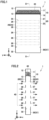
Fig. 1 is a schematic diagram of a carbon dioxide capturing apparatus according to a first embodiment. -
Fig. 2 is a schematic cross section of the carbon dioxide capturing apparatus according to the first embodiment taken along a cross-sectional line II-II indicated inFig. 1 . -
Fig. 3 is a schematic diagram of the carbon dioxide capturing apparatus according to the first embodiment. -
Fig. 4 is a schematic cross section of the carbon dioxide capturing apparatus according to the first embodiment taken along a cross-sectional line IV-IV indicated inFig. 3 . -
Fig. 5 is a schematic diagram of the carbon dioxide capturing apparatus according to the first embodiment. -
Fig. 6 is a schematic cross section of the carbon dioxide capturing apparatus according to the first embodiment taken along a cross-sectional line VI-VI indicated inFig. 5 . -
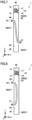
Fig. 7 is a schematic cross section of a carbon dioxide capturing apparatus according to a first exemplary variation of the first embodiment. -
Fig. 8 is a schematic cross section of a carbon dioxide capturing apparatus according to a second exemplary variation of the first embodiment. -
Fig. 9 is a schematic cross section of a carbon dioxide capturing apparatus according to a third exemplary variation of the first embodiment. -
Fig. 10 is a schematic cross section of a carbon dioxide capturing apparatus according to a fourth exemplary variation of the first embodiment. -
Fig. 11 is a schematic cross section of a carbon dioxide capturing apparatus according to a fifth exemplary variation of the first embodiment. -
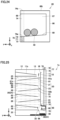
Fig. 12 is a schematic diagram for illustrating a first example of installing the carbon dioxide capturing apparatus according to the first embodiment. -
Fig. 13 is a schematic diagram for illustrating a second example of installing the carbon dioxide capturing apparatus according to the first embodiment. -
Fig. 14 is a schematic diagram for illustrating a third example of installing the carbon dioxide capturing apparatus according to the first embodiment. -
Fig. 15 is a schematic diagram of a carbon dioxide capturing apparatus according to a second embodiment. -
Fig. 16 is a schematic diagram of the carbon dioxide capturing apparatus according to the second embodiment. -
Fig. 17 is a schematic diagram of the carbon dioxide capturing apparatus according to the second embodiment. -
Fig. 18 is a schematic diagram of a carbon dioxide capturing apparatus according to a third embodiment. -
Fig. 19 is a schematic diagram of the carbon dioxide capturing apparatus according to the third embodiment. -
Fig. 20 is a schematic diagram of a transport container included in the carbon dioxide capturing apparatus according to the third embodiment. -
Fig. 21 is a schematic cross section of the transport container included in the carbon dioxide capturing apparatus according to the third embodiment, as taken along a cross-sectional line XXI-XXI indicated inFig. 20 . -
Fig. 22 is a schematic diagram of the carbon dioxide capturing apparatus according to the third embodiment. -
Fig. 23 is a schematic diagram of the transport container included in the carbon dioxide capturing apparatus according to the third embodiment. -
Fig. 24 is a schematic cross section of the transport container included in the carbon dioxide capturing apparatus according to the third embodiment, as taken along a cross-sectional line XXIV-XXIV indicated inFig. 23 . -
Fig. 25 is a schematic diagram of the carbon dioxide capturing apparatus according to the third embodiment. -
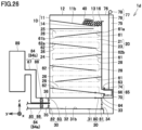
Fig. 26 is a schematic diagram of a carbon dioxide capturing apparatus according to a fourth embodiment. -
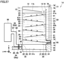
Fig. 27 is a schematic diagram of the carbon dioxide capturing apparatus according to the fourth embodiment. -
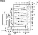
Fig. 28 is a schematic diagram of the carbon dioxide capturing apparatus according to the fourth embodiment. -
Fig. 29 is a schematic diagram of the carbon dioxide capturing apparatus according to the fourth embodiment. -
Fig. 30 is a schematic diagram of the carbon dioxide capturing apparatus according to the fourth embodiment. -
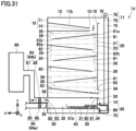
Fig. 31 is a schematic diagram of the carbon dioxide capturing apparatus according to the fourth embodiment. -
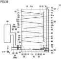
Fig. 32 is a schematic diagram of the carbon dioxide capturing apparatus according to the fourth embodiment. -
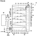
Fig. 33 is a schematic diagram of the carbon dioxide capturing apparatus according to the fourth embodiment. -
Fig. 34 is a schematic diagram of a carbon dioxide capturing apparatus according to an exemplary variation of the fourth embodiment. -
Fig. 35 is a schematic diagram of the carbon dioxide capturing apparatus according to the exemplary variation of the fourth embodiment. -
Fig. 36 is a schematic diagram of the carbon dioxide capturing apparatus according to the exemplary variation of the fourth embodiment. -
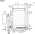
Fig. 37 is a schematic diagram of the carbon dioxide capturing apparatus according to the exemplary variation of the fourth embodiment. -
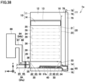
Fig. 38 is a schematic diagram of the carbon dioxide capturing apparatus according to the exemplary variation of the fourth embodiment. -
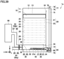
Fig. 39 is a schematic diagram of the carbon dioxide capturing apparatus according to the exemplary variation of the fourth embodiment. -
Fig. 40 is a schematic diagram of the carbon dioxide capturing apparatus according to the exemplary variation of the fourth embodiment. -
Fig. 41 is a schematic cross section of a carbon dioxide capturing apparatus according to a fifth embodiment. -
Fig. 42 is a schematic cross section of the carbon dioxide capturing apparatus according to the fifth embodiment. -
Fig. 43 is a schematic cross section of the carbon dioxide capturing apparatus according to the fifth embodiment. -
Fig. 44 is a schematic cross section of a carbon dioxide capturing apparatus according to a first exemplary variation of the fifth embodiment. -
Fig. 45 is a schematic cross section of a carbon dioxide capturing apparatus according to a second exemplary variation of the fifth embodiment. -
Fig. 46 is a schematic cross section of the carbon dioxide capturing apparatus according to the second exemplary variation of the fifth embodiment. - Hereinafter, embodiments of the present disclosure will be described. Identical components are identically denoted and will not be described repeatedly.
- A carbon
dioxide capturing apparatus 1 according to a first embodiment will now be described with reference toFigs. 1 to 6 . Carbondioxide capturing apparatus 1 comprises astorage unit 10, anadsorption unit 20, and acollection unit 30. -
Storage unit 10 accommodates an adsorbent 40.Adsorbent 40 can adsorb carbon dioxide.Adsorbent 40 is a solid adsorbent carrying amine, zeolite, silica gel, diatomite, alumina, or activated carbon for example. Although not particularly limited,adsorbent 40 has a spherical shape or a cylindrical shape for example.Figs. 1 to 6 show adsorbent 40 darker asadsorbent 40 adsorbs more carbon dioxide.Storage unit 10 is disposed aboveadsorption unit 20. -
Storage unit 10 includes astorage body 11 and avalve 14. Insidestorage body 11 is formed astorage space 12 to storeadsorbent 40. Storage body 11 (specifically, a bottom portion of storage body 11) is provided with anopening 13.Opening 13 communicates withstorage space 12 and an adsorption space ofadsorption unit 20.Valve 14 opens and closesopening 13. Whenvalve 14 closes opening 13,adsorbent 40 is stored instorage unit 10. Whenvalve 14 opens opening 13,adsorbent 40 falls toward the adsorption space ofadsorption unit 20 by the self-weight ofadsorbent 40. -
Adsorption unit 20 is disposed betweenstorage unit 10 andcollection unit 30. Inadsorption unit 20,adsorbent 40 comes into contact with agas 43 containing carbon dioxide and adsorbs the carbon dioxide contained ingas 43. Whilegas 43 is not particularly limited insofar as it is a gas containing carbon dioxide, it is for example air. - Specifically,
adsorption unit 20 includes afront wall 21, arear wall 22 opposite tofront wall 21, aside wall 23, and aside wall 24 opposite toside wall 23.Side walls front wall 21 andrear wall 22. Anadsorption space 25 is formed insideadsorption unit 20.Front wall 21,rear wall 22, andside walls adsorption space 25. As shown inFigs. 1 and 2 ,front wall 21 has a width larger than that of each ofside walls Rear wall 22 has a width larger than that of each ofside walls front wall 21 is a length offront wall 21 in a direction (a y direction) perpendicular to a direction of falling through adsorption unit 20 (i.e., a - z direction). The width ofrear wall 22 is a length ofrear wall 22 in the direction (the y direction) perpendicular to the direction of falling through adsorption unit 20 (i.e., the - z direction). The width ofside wall 23 is a length ofside wall 23 in the direction (an x direction) perpendicular to the direction of falling through adsorption unit 20 (i.e., the - z direction). The width ofside wall 24 is a length ofside wall 24 in the direction (the x direction) perpendicular to the direction of falling through adsorption unit 20 (i.e., the - z direction). - Adsorption unit 20 (specifically, front wall 21) is provided with an
opening 26.Gas 43 containing carbon dioxide flows through opening 26 intoadsorption space 25. In the present embodiment, opening 26 is an inlet forgas 43.Opening 26 has a width for example of 60% or more and 100% or less of the width offront wall 21.Opening 26 may have a width of 80% or more and 95% or less of the width offront wall 21. In the present specification, the width of opening 26 is a length of opening 26 in a direction (the y direction) perpendicular to the direction of falling through adsorption unit 20 (i.e., the - z direction). While in the presentembodiment adsorption unit 20 is provided with a plurality ofopenings 26,adsorption unit 20 may be provided with at least oneopening 26. - Adsorption unit 20 (specifically, rear wall 22) is provided with an
opening 27.Gas 43 flows out ofadsorption space 25 throughopening 27. In the present embodiment, opening 27 is an outlet forgas 43.Opening 27 has a width for example of 60% or more and 100% or less of the width ofrear wall 22. In the present specification, the width of opening 27 is a length of opening 27 in a direction (the y direction) perpendicular to the direction of falling through adsorption unit 20 (i.e., the - z direction). While in the presentembodiment adsorption unit 20 is provided with a plurality ofopenings 27,adsorption unit 20 may be provided with at least oneopening 27.Opening 27 faces opening 26 for example in a direction (the x direction) perpendicular to the direction of falling through adsorption unit 20 (i.e., the - z direction). -
Adsorbent 40 falls fromstorage unit 10 throughadsorption space 25 towardcollection unit 30 by the self-weight ofadsorbent 40.Adsorbent 40 falls in a direction (or the - z direction), which is for example the direction of gravity.Gas 43 is introduced throughopening 26 intoadsorption space 25 in a direction (e.g., a + x direction) intersecting the direction in which adsorbent 40 falls (e.g., the - z direction).Adsorbent 40 inadsorption space 25 comes into contact withgas 43 and adsorbs carbon dioxide contained ingas 43.Gas 43 having carbon dioxide removed byadsorbent 40 flows out ofadsorption space 25 throughopening 27. -
Adsorption unit 20 larger in size in the direction in which adsorbent 40 falls (e.g., the - z direction) allows adsorbent 40 to be in contact withgas 43 for a longer period of time to allow adsorbent 40 to more efficiently adsorb carbon dioxide. Accordingly, whengas 43 has a low concentration of carbon dioxide,adsorption unit 20 is increased in size in the direction in which adsorbent 40 falls (e.g., the - z direction). Whengas 43 has a high concentration of carbon dioxide,adsorption unit 20 may have a small size in the direction in which adsorbent 40 falls (e.g., the - z direction). -
Collection unit 30 collects adsorbent 40 having adsorbed carbon dioxide contained ingas 43.Collection unit 30 is disposed belowadsorption unit 20.Collection unit 30 includes acollection body 31.Inside collection body 31 is formed acollection space 32 to accommodate adsorbent 40 having adsorbed carbon dioxide. Collection body 31 (specifically, a top portion of collection body 31) is provided with anopening 33.Opening 33 communicates withadsorption space 25 andcollection space 32.Collection unit 30 may be detachably attachable toadsorption unit 20. - An operation of carbon
dioxide capturing apparatus 1 and a carbon dioxide capturing method according to the present embodiment will now be described with reference toFigs. 1 to 6 . - As shown in
Figs. 1 and 2 ,valve 14 closes opening 13.Adsorbent 40 is stored instorage unit 10. - As shown in
Figs. 3 and 4 ,valve 14 opensopening 13.Adsorbent 40 falls towardadsorption space 25 ofadsorption unit 20 by the self-weight ofadsorbent 40. Inadsorption unit 20,adsorbent 40 falls fromstorage unit 10 throughadsorption space 25 towardcollection unit 30 by the self-weight ofadsorbent 40.Gas 43 is introduced throughopening 26 intoadsorption space 25 in a direction (e.g., the + x direction) intersecting the direction in which adsorbent 40 falls (e.g., the - z direction).Adsorbent 40 inadsorption space 25 comes into contact withgas 43 and adsorbs carbon dioxide contained ingas 43.Gas 43 having carbon dioxide removed byadsorbent 40 flows out ofadsorption space 25 throughopening 27. -
Adsorbent 40 having adsorbed carbon dioxide contained ingas 43 falls fromadsorption unit 20 towardcollection unit 30 by the self-weight ofadsorbent 40. As shown inFigs. 5 and 6 ,adsorbent 40 having adsorbed carbon dioxide passes throughopening 33 and is accommodated incollection space 32 ofcollection unit 30.Adsorbent 40 having adsorbed carbon dioxide is collected incollection unit 30. - As shown in
Fig. 7 , carbondioxide capturing apparatus 1 of a first exemplary variation of the present embodiment has oneopening 26 provided at adsorption unit 20 (specifically through front wall 21), and oneopening 27 provided at adsorption unit 20 (specifically through rear wall 22).Opening 27 is disposed offset from thecorresponding opening 26 in the direction in which adsorbent 40 falls (e.g., the - z direction). Depending on the direction in whichgas 43 flows, opening 26 may function as an inlet forgas 43 andopening 27 may function as an outlet forgas 43, or opening 27 may function as an inlet forgas 43 andopening 26 may function as an outlet forgas 43. - As shown in
Fig. 8 , carbondioxide capturing apparatus 1 of a second exemplary variation of the present embodiment has oneopening 26 and oneopening 27 provided atadsorption unit 20 throughfront wall 21.Opening 27 is disposed offset from thecorresponding opening 26 in the direction in which adsorbent 40 falls (e.g., the - z direction). Depending on the direction in whichgas 43 flows, opening 26 may function as an inlet forgas 43 andopening 27 may function as an outlet forgas 43, or opening 27 may function as an inlet forgas 43 andopening 26 may function as an outlet forgas 43. Carbondioxide capturing apparatus 1 of the second exemplary variation of the present embodiment is suitable for installation on a wall (not shown). - As shown in
Fig. 9 , carbondioxide capturing apparatus 1 of a third exemplary variation of the present embodiment has oneopening 28 provided atadsorption unit 20 throughfront wall 21.Opening 28 is larger than each ofopenings Opening 28 functions as an inlet and an outlet forgas 43. Depending on the direction in whichgas 43 flows, an upper portion of opening 28 may function as an inlet forgas 43 and a lower portion of opening 28 may function as an outlet forgas 43, or the lower portion of opening 28 may function as an inlet forgas 43 and the upper portion of opening 28 may function as an outlet forgas 43. Carbondioxide capturing apparatus 1 of the third exemplary variation of the present embodiment is suitable for installation on a wall (not shown). - As shown in
Fig. 10 , carbondioxide capturing apparatus 1 of a fourth exemplary variation of the present embodiment includes an eave 29 provided atadsorption unit 20 above each ofopenings Eave 29 prevents rain, snow or sunlight from enteringadsorption space 25.Eave 29 may be provided above one ofopening 26 oropening 27. - As shown in
Fig. 11 , for carbondioxide capturing apparatus 1 of a fifth exemplary variation of the present embodiment,adsorption unit 20 includes a net 46 that passesgas 43 and does not pass adsorbent 40.Net 46 covers opening 27. Although not particularly limited, net 46 is formed of metal such as stainless steel.Net 46 may further coveropening 26.Net 46 that covers both opening 26 andopening 27 can prevent adsorbent 40 from exitingadsorption unit 20 asadsorbent 40 is carried away bygas 43 whengas 43 flows intoadsorption unit 20 in various directions. - As shown in
Figs. 12 to 14 , carbondioxide capturing apparatus 1 is installed for example on abuilding 50.Building 50 includes aside wall 51 and arooftop 52.Building 50 includes, but not limited to, a high-rise building or a condominium, for example. - Specifically, as shown in
Fig. 12 , in a first example of installation according to the present embodiment, carbondioxide capturing apparatus 1 is installed onside wall 51 ofbuilding 50. As shown inFig. 13 , in a second example of installation according to the present embodiment, carbondioxide capturing apparatus 1 is installed onrooftop 52 ofbuilding 50. When carbondioxide capturing apparatus 1 is thus installed outdoors, air blown outdoors causesgas 43 to flow intoadsorption unit 20, and carbondioxide capturing apparatus 1 can capture carbon dioxide contained ingas 43. - As shown in
Fig. 14 , in a third example of installation according to the present embodiment, carbondioxide capturing apparatus 1 is installed in front of anair intake port 56 of an air conditioningoutdoor unit 55. In order to facilitate installation of carbondioxide capturing apparatus 1, carbondioxide capturing apparatus 1 may be supported by air conditioningoutdoor unit 55. Although not particularly limited, air conditioningoutdoor unit 55 is installed outdoors such as onrooftop 52 of building 50, for example. Air conditioningoutdoor unit 55 is provided withair intake port 56 and anair exhaust port 57. Carbondioxide capturing apparatus 1 and air conditioningoutdoor unit 55 are included in an airconditioning ventilation system 2 of the present embodiment. In the present specification, airconditioning ventilation system 2 means a system that performs air conditioning, ventilation, or both air conditioning and ventilation for building 50. - Carbon
dioxide capturing apparatus 1, airconditioning ventilation system 2, and the carbon dioxide capturing method according to the present embodiment have an effect, as described below. - Carbon
dioxide capturing apparatus 1 of the present embodiment comprisesstorage unit 10 to accommodate adsorbent 40,collection unit 30 to collect adsorbent 40, andadsorption unit 20.Adsorption space 25 is formed insideadsorption unit 20.Adsorption unit 20 is provided with an inlet (e.g., opening 26) through whichgas 43 containing carbon dioxide flows intoadsorption space 25.Adsorption unit 20 is disposed betweenstorage unit 10 andcollection unit 30.Adsorbent 40 falls fromstorage unit 10 throughadsorption space 25 towardcollection unit 30 by the self-weight ofadsorbent 40.Gas 43 is introduced through the inlet intoadsorption space 25 in a direction intersecting a direction in which adsorbent 40 falls.Adsorbent 40 adsorbs inadsorption space 25 carbon dioxide contained ingas 43. - Carbon
dioxide capturing apparatus 1 introducesgas 43 intoadsorption space 25 in a direction intersecting the direction in which adsorbent 40 falls. Thus,gas 43 receives reduced flow resistance fromadsorbent 40. Carbondioxide capturing apparatus 1 is also applicable togas 43 having a lower pressure and can also be further reduced in size. Further, adsorbent 40 falls fromstorage unit 10 throughadsorption space 25 towardcollection unit 30 by the self-weight ofadsorbent 40. This can eliminates the necessity of using electric power to transport adsorbent 40 fromstorage unit 10 to collection unit 30 (for example using a pneumatic conveyor). - In carbon
dioxide capturing apparatus 1 of the present embodiment,storage unit 10 is disposed aboveadsorption unit 20.Collection unit 30 is disposed belowadsorption unit 20. - Accordingly, adsorbent 40 falls from
storage unit 10 tocollection unit 30 throughadsorption unit 20 by the self-weight ofadsorbent 40. This can eliminates the necessity of using electric power to transport adsorbent 40 fromstorage unit 10 tocollection unit 30. - In carbon
dioxide capturing apparatus 1 of the present embodiment,storage unit 10 includesstorage body 11 and a first valve (valve 14). Insidestorage body 11 is formedstorage space 12 to storeadsorbent 40.Storage body 11 is provided with a first opening (opening 13). The first opening communicates withstorage space 12 andadsorption space 25. The first valve opens and closes the first opening. - The first valve (valve 14) allows
storage unit 10 to store a sufficient amount ofadsorbent 40 so that subsequently the sufficient amount ofadsorbent 40 can be supplied toadsorption unit 20. Carbon dioxide contained ingas 43 can be captured more efficiently. - In carbon
dioxide capturing apparatus 1 of the present embodiment,adsorption unit 20 includes a first wall (front wall 21) and a second wall (side wall 23) connected to the first wall. The first and second walls define a portion ofadsorption space 25. The first wall has a larger width than the second wall. An inlet (e.g., opening 26) is provided through the first wall. - This allows the inlet (e.g., opening 26) to have an increased area.
More gas 43 can be introduced intoadsorption space 25 through the inlet. Carbon dioxide contained ingas 43 can be captured more efficiently. - In carbon
dioxide capturing apparatus 1 of the present embodiment, the inlet (e.g., opening 26) has a width of 60% or more and 100% or less of that of the first wall (front wall 21). - This allows the inlet (e.g., opening 26) to have an increased area.
More gas 43 can be introduced intoadsorption space 25 through the inlet. Carbon dioxide contained ingas 43 can be captured more efficiently. - In carbon
dioxide capturing apparatus 1 of the present embodiment,adsorption unit 20 includeseave 29 provided above the inlet (e.g., opening 26). -
Eave 29 prevents rain, snow or sunlight from enteringadsorption space 25. This can prevent rain or snow from coming into contact withadsorbent 40 or prevent adsorbent 40 from being exposed to sunlight. This can in turn prevent adsorbent 40 from providing poor adsorption attributed to rain, snow, or sunlight. Carbon dioxide contained ingas 43 can be captured more efficiently for a longer period of time. - In carbon
dioxide capturing apparatus 1 of the present embodiment,adsorption unit 20 includes net 46 allowinggas 43 to pass therethrough and preventingadsorbent 40 from passing therethrough.Adsorption unit 20 is provided with an outlet (e.g., opening 27) through whichgas 43 flows out ofadsorption space 25.Net 46 covers the outlet. -
Net 46 can passgas 43 having carbon dioxide removed byadsorbent 40 and prevent adsorbent 40 from being carried away bygas 43 and exitingadsorption unit 20 through the outlet (e.g., opening 27). - Carbon
dioxide capturing apparatus 1 of the present embodiment is installed onrooftop 52 orside wall 51 ofbuilding 50. - In many cases, outside air flows at a faster velocity around
rooftop 52 of building 50 than on the ground. By installing carbondioxide capturing apparatus 1 on building 50 atrooftop 52,more gas 43 can be introduced intoadsorption space 25. Carbon dioxide contained ingas 43 can be captured more efficiently. - Installing carbon
dioxide capturing apparatus 1 on building 50 atside wall 51 allowsadsorption unit 20 to be increased in size in the direction in which adsorbent 40 falls, and also allows flow of outside air to be utilized to introducegas 43 intoadsorption space 25.More gas 43 can be introduced intoadsorption space 25. Carbon dioxide contained ingas 43 can be captured more efficiently. - Air
conditioning ventilation system 2 of the present embodiment comprises carbondioxide capturing apparatus 1 and air conditioningoutdoor unit 55. Air conditioningoutdoor unit 55 is provided withair intake port 56. Carbondioxide capturing apparatus 1 is installed in front ofair intake port 56 of air conditioningoutdoor unit 55. - Air
conditioning ventilation system 2 comprising carbondioxide capturing apparatus 1 is also applicable togas 43 having a lower pressure and can also be further reduced in size. Further, by installing carbondioxide capturing apparatus 1 in front ofair intake port 56 of air conditioningoutdoor unit 55,gas 43 can be introduced intoadsorption space 25 by utilizing a flow of outside air that is created by air conditioningoutdoor unit 55. Carbon dioxide contained ingas 43 can be captured more efficiently. Further, even when air conditioningoutdoor unit 55 is stopped and there is no air flow created by air conditioningoutdoor unit 55, air blown outdoors causesgas 43 to flow intoadsorption unit 20, and carbondioxide capturing apparatus 1 can thus capture carbon dioxide contained ingas 43. - The carbon dioxide capturing method of the present embodiment comprises adsorbing carbon dioxide contained in
gas 43 onadsorbent 40 by bringingadsorbent 40 into contact withgas 43 containing the carbon dioxide by allowingadsorbent 40 to fall throughadsorption space 25 ofadsorption unit 20 by the self-weight ofadsorbent 40.Gas 43 is introduced intoadsorption space 25 in a direction intersecting the direction in which adsorbent 40 falls. The carbon dioxide capturing method of the present embodiment further comprises collectingadsorbent 40 having adsorbed the carbon dioxide. - In the carbon dioxide capturing method of the present embodiment,
gas 43 is introduced intoadsorption space 25 in a direction intersecting the direction in which adsorbent 40 falls. Thus,gas 43 receives reduced flow resistance fromadsorbent 40. The carbon dioxide capturing method of the present embodiment is also applicable togas 43 having a lower pressure. Further, the carbon dioxide capturing method of the present embodiment allows carbondioxide capturing apparatus 1 to be further reduced in size. Further, in the carbon dioxide capturing method of the present embodiment, adsorbent 40 falls throughadsorption space 25 by the self-weight ofadsorbent 40. This can eliminates the necessity of using electric power to transportadsorbent 40. - A carbon
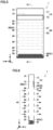
dioxide capturing apparatus 1b according to a second embodiment will now be described with reference toFigs. 15 to 17 . Carbondioxide capturing apparatus 1b of the present embodiment is similar in configuration to carbondioxide capturing apparatus 1 of the first embodiment, except mainly for the following. - In carbon
dioxide capturing apparatus 1b,storage body 11 includes aninclined bottom plate 11b.Inclined bottom plate 11b defines a bottom portion ofstorage body 11.Inclined bottom plate 11b gradually descends towardopening 13. Whenvalve 14 closes opening 13,adsorbent 40 is present oninclined bottom plate 11b andvalve 14. - Carbon
dioxide capturing apparatus 1b further comprises a plurality ofinclined plates dioxide capturing apparatus 1b may include at least one inclined plate.Inclined plates adsorption space 25.Inclined plates -
Inclined plate 61 includes anend 61a and anend 61b opposite to end 61a.End 61a is fixed to adsorption unit 20 (specifically, side wall 23).End 61b is separated from adsorption unit 20 (specifically, side wall 24), and a gap is formed betweenend 61b and adsorption unit 20 (specifically, side wall 24).End 61a is higher in level thanend 61b. A distance betweenend 61a andstorage unit 10 is smaller than a distance betweenend 61b andstorage unit 10.Inclined plate 62 includes anend 62a and anend 62b opposite to end 62a.End 62a is fixed to adsorption unit 20 (specifically, side wall 24).End 62b is separated from adsorption unit 20 (specifically, side wall 23), and a gap is formed betweenend 62b and adsorption unit 20 (specifically, side wall 23).End 62a is higher in level thanend 62b. A distance betweenend 62a andstorage unit 10 is smaller than a distance betweenend 62b andstorage unit 10. -
Adsorbent 40 rolls oninclined plates adsorbent 40. As such,adsorbent 40 can have a larger surface area to come into contact withgas 43.Adsorbent 40 comes into contact withgas 43 for an increased period of time. More carbon dioxide is adsorbed byadsorbent 40.Adsorbent 40 may have any shape that allows the adsorbent to roll oninclined plates - An operation of carbon
dioxide capturing apparatus 1b and a carbon dioxide capturing method according to the present embodiment will now be described with reference toFigs. 15 to 17 . - As shown in
Fig. 15 ,valve 14 closes opening 13. As in the step shown inFigs. 1 and 2 according to the first embodiment,adsorbent 40 is stored instorage unit 10.Adsorbent 40 is present oninclined bottom plate 11b andvalve 14. - As shown in
Fig. 16 ,valve 14 opensopening 13.Adsorbent 40 falls towardadsorption space 25 ofadsorption unit 20 by the self-weight ofadsorbent 40. Inadsorption unit 20,adsorbent 40 falls towardcollection unit 30 while rolling oninclined plates adsorbent 40. Specifically, adsorbent 40 rolls oninclined plate 61 towardend 61b by the self-weight ofadsorbent 40.Adsorbent 40 falls ontoinclined plate 62 through the gap betweenend 61b and adsorption unit 20 (specifically, side wall 24) by the self-weight ofadsorbent 40.Adsorbent 40 rolls oninclined plate 62 towardend 62b by the self-weight ofadsorbent 40.Adsorbent 40 falls ontoinclined plate 61 through the gap betweenend 62b and adsorption unit 20 (specifically, side wall 23) by the self-weight ofadsorbent 40. -
Gas 43 is introduced throughopening 26 intoadsorption space 25 in a direction (e.g., the + x direction) intersecting the direction in which adsorbent 40 falls (e.g., the - z direction).Adsorbent 40 inadsorption space 25 comes into contact withgas 43 while rolling oninclined plates gas 43.Gas 43 having carbon dioxide removed byadsorbent 40 flows out ofadsorption space 25 through opening 27 (seeFigs. 2 ,4 and6 ). -
Adsorbent 40 having adsorbed carbon dioxide contained ingas 43 falls from one ofinclined plates collection unit 30 by the self-weight ofadsorbent 40. Specifically, the adsorbent falls towardcollection unit 30 through a gap formed between one ofinclined plates Fig. 17 ,adsorbent 40 having adsorbed carbon dioxide passes throughopening 33 and is accommodated incollection space 32 ofcollection unit 30.Adsorbent 40 having adsorbed carbon dioxide is collected incollection unit 30. - Carbon
dioxide capturing apparatus 1b and the carbon dioxide capturing method according to the present embodiment have the following effects in addition to the effects of carbondioxide capturing apparatus 1 and the carbon dioxide capturing method according to the first embodiment. - Carbon
dioxide capturing apparatus 1b of the present embodiment further comprises at least one inclined plate (e.g.,inclined plates 61 and 62) disposed inadsorption space 25 and inclined with respect to a horizontal plane.Adsorbent 40 rolls on at least one inclined plate by the self-weight ofadsorbent 40. -
Adsorbent 40 rolling on at least one inclined plate (e.g.,inclined plates 61 and 62) has an increased surface area to come into contact withgas 43 containing carbon dioxide. More carbon dioxide can be adsorbed byadsorbent 40 in a shorter period of time. Carbon dioxide can be captured more efficiently. Carbondioxide capturing apparatus 1b can be reduced in size. - In carbon
dioxide capturing apparatus 1b of the present embodiment, at least one inclined plate (e.g., inclined plate 61) includes a first end (e.g.,end 61a) fixed toadsorption unit 20 and a second end (e.g.,end 61b) opposite to the first end. A first distance between the first end andstorage unit 10 is smaller than a second distance between the second end andstorage unit 10. - Therefore, adsorbent 40 rolls on at least one inclined plate (e.g., inclined plate 61).
Adsorbent 40 has an increased surface area to come into contact withgas 43 containing carbon dioxide. More carbon dioxide can be adsorbed byadsorbent 40 in a shorter period of time. Carbon dioxide can be captured more efficiently. Carbondioxide capturing apparatus 1b can be reduced in size. - In carbon
dioxide capturing apparatus 1b of the present embodiment, at least one inclined plate is a plurality of inclined plates (e.g.,inclined plates 61 and 62). - Therefore, adsorbent 40 has a further increased surface area to come into contact with
gas 43 containing carbon dioxide.Adsorbent 40 comes into contact withgas 43 for an increased period of time. More carbon dioxide can be adsorbed byadsorbent 40. Carbon dioxide can be captured more efficiently. - In carbon
dioxide capturing apparatus 1b of the present embodiment,adsorbent 40 has a spherical shape or a cylindrical shape. - Therefore, adsorbent 40 rolls on at least one inclined plate (e.g.,
inclined plates 61 and 62).Adsorbent 40 has an increased surface area to come into contact withgas 43 containing carbon dioxide. More carbon dioxide can be adsorbed byadsorbent 40 in a shorter period of time. Carbon dioxide can be captured more efficiently. - In the carbon dioxide capturing method of the present embodiment, allowing
adsorbent 40 to fall by the self-weight ofadsorbent 40 includes rollingadsorbent 40 on at least one inclined plate (e.g.,inclined plates 61 and 62) disposed inadsorption space 25 and inclined with respect to a horizontal plane. -
Adsorbent 40 rolling on at least one inclined plate (e.g.,inclined plates 61 and 62) has an increased surface area to come into contact withgas 43 containing carbon dioxide. More carbon dioxide can be adsorbed byadsorbent 40 in a shorter period of time. The carbon dioxide capturing method of the present embodiment allows carbon dioxide to be captured more efficiently and allows carbondioxide capturing apparatus 1b to be reduced in size. - A carbon
dioxide capturing apparatus 1c according to a third embodiment will now be described with reference toFigs. 18 to 25 . Carbondioxide capturing apparatus 1c of the present embodiment is similar in configuration to carbondioxide capturing apparatus 1b of the second embodiment, except mainly for the following. - As shown in
Figs. 18, 19 ,22 , and25 , in carbondioxide capturing apparatus 1c,storage unit 10 is provided with anopening 16.Opening 16 communicates withstorage space 12 and apassage 75 for atransport container 65.Adsorption unit 20 is provided with anopening 63 communicating withadsorption space 25 andpassage 75 fortransport container 65.Opening 63 faces a lower end of one ofinclined plates end 62b of inclined plate 62). -
Adsorption unit 20 includes avalve 64.Valve 64 is provided at the lower end of one ofinclined plates end 62b of inclined plate 62).Valve 64 is switchable between a first valve position (seeFigs. 18 and 19 ) and a second valve position (seeFigs. 22 and25 ). As shown inFigs. 18 and 19 , whenvalve 64 is in the first valve position,valve 64 guides adsorbent 40 to opening 63 and hence transportcontainer 65. As shown inFigs. 22 and25 , whenvalve 64 is in the second valve position,valve 64 guides adsorbent 40 to opening 33 and hencecollection unit 30. - As shown in
Figs. 18 to 25 , carbondioxide capturing apparatus 1c further comprisestransport container 65 and adriving device 77. In order to reuse adsorbent 40 having adsorbed carbon dioxide,transport container 65 and drivingdevice 77transport adsorbent 40 having adsorbed carbon dioxide fromadsorption unit 20 tostorage unit 10. -
Transport container 65 includes acar 66 and ashutter 70.Transport container 65 may further include aspring 73 and anoperation rod 74. -
Car 66 has atop surface 66t.Car 66 is internally provided with anaccommodation space 67 to accommodateadsorbent 40.Car 66 is provided with anopening 68 communicating withaccommodation space 67.Car 66 includes aninclined bottom surface 69 defining a bottom surface ofaccommodation space 67.Inclined bottom surface 69 gradually descends towardopening 68. -
Shutter 70 includes ashutter body 71 and aprojection 72 projecting fromshutter body 71. The shutter (specifically, shutter body 71) opens and closes a portion of opening 68 ofcar 66. - Specifically,
spring 73 andoperation rod 74 are connected toprojection 72.Spring 73 biases shutter 70 upward.Operation rod 74 includes alower end 74a and anupper end 74b opposite tolower end 74a.Operation rod 74 haslower end 74a coupled toprojection 72. - As shown in
Figs. 18 and 19 , whentransport container 65 is in the first position,top surface 66t ofcar 66 is away from aceiling 76 ofpassage 75 fortransport container 65. As shown inFigs. 18 to 21 ,shutter 70 is biased upward byspring 73. Therefore, shutter 70 (specifically, shutter body 71) closes a portion of opening 68 ofcar 66.Upper end 74b ofoperation rod 74 projects fromtop surface 66t ofcar 66. - In contrast, when
transport container 65 is in the second position as shown inFig. 22 ,top surface 66t ofcar 66 comes into contact withceiling 76 ofpassage 75 fortransport container 65. As shown inFigs. 22 to 24 ,operation rod 74 moves downward against the biasing force ofspring 73.Upper end 74b ofoperation rod 74 is flush withtop surface 66t ofcar 66.Spring 73 is compressed. Shutter 70 (specifically, shutter body 71) opensopenings 68 ofcar 66 entirely. -
Transport container 65 is driven by drivingdevice 77 to move throughpassage 75. In the present embodiment, drivingdevice 77 movestransport container 65 between the first position and the second position. As shown inFigs. 18 and 19 , whentransport container 65 is in the first position,transport container 65 faces adsorption unit 20 (e.g., opening 63). Whentransport container 65 is in the second position, as shown inFig. 22 ,transport container 65 faces storage unit 10 (e.g., opening 16). Specifically, drivingdevice 77 includes a hoistingmachine 78 and arope 79.Rope 79 is connected to transport container 65 (specifically, car 66) and hoistingmachine 78.Transport container 65 ascends fromadsorption unit 20 tostorage unit 10 or descends fromstorage unit 10 toadsorption unit 20 by using hoistingmachine 78 andrope 79. - An operation of carbon
dioxide capturing apparatus 1c and a carbon dioxide capturing method according to the present embodiment will now be described with reference toFigs. 18 to 25 . - As shown in
Fig. 18 ,valve 14 closes opening 13. As in the step shown inFig. 15 according to the second embodiment,adsorbent 40 is stored instorage unit 10. - As shown in
Fig. 19 ,valve 14 opensopening 13. As in the step shown inFig. 16 according to the second embodiment, adsorbent 40 falls towardadsorption space 25 ofadsorption unit 20 by the self-weight ofadsorbent 40. Inadsorption unit 20,adsorbent 40 falls towardcollection unit 30 while rolling oninclined plates adsorbent 40.Adsorbent 40 inadsorption space 25 comes into contact withgas 43 while rolling oninclined plates gas 43. - As shown in
Fig. 19 , whentransport container 65 is in the first position, adsorbent 40 having fallen throughadsorption space 25 is accommodated intransport container 65. Specifically,transport container 65 is in the first position and faces adsorption unit 20 (e.g., opening 63).Valve 64 is in the first valve position and guides adsorbent 40 to opening 63 and hence transportcontainer 65.Adsorbent 40 having adsorbed carbon dioxide rolls onvalve 64, passes throughopening 63, and is accommodated inaccommodation space 67 ofcar 66. Whentransport container 65 is in the first position, shutter 70 (specifically, shutter body 71) closes a portion of opening 68 ofcar 66 as shown inFigs. 19 to 21 . Therefore, adsorbent 40 accommodated inaccommodation space 67 ofcar 66 remains inaccommodation space 67 ofcar 66. - As shown in
Fig. 22 , drivingdevice 77 is operated to movetransport container 65 from the first position (seeFigs. 18 and 19 ) to the second position (seeFig. 22 ). Specifically, hoistingmachine 78 is used to windrope 79.Transport container 65 connected to rope 79 moves from the first position to the second position. - As shown in
Fig. 22 , whentransport container 65 is in the second position,adsorbent 40 is supplied fromtransport container 65 tostorage unit 10. Specifically, whentransport container 65 is in the second position,transport container 65 faces opening 16, andtop surface 66t ofcar 66 comes into contact withceiling 76 ofpassage 75 fortransport container 65.Upper end 74b ofoperation rod 74 comes into contact withceiling 76, andoperation rod 74 moves downward against the biasing force ofspring 73.Upper end 74b ofoperation rod 74 is flush withtop surface 66t ofcar 66.Shutter 70 coupled tooperation rod 74 also moves downward. Shutter 70 (specifically, shutter body 71) opens opening 68 ofcar 66 entirely.Adsorbent 40 moves alonginclined bottom surface 69. For example, adsorbent 40 rolls oninclined bottom surface 69 by the self-weight ofadsorbent 40.Adsorbent 40 moves fromaccommodation space 67 ofcar 66 throughopening 16 tostorage space 12 ofstorage unit 10.Valve 14 opensopening 13.Adsorbent 40 is supplied toadsorption space 25 ofadsorption unit 20 throughopening 13. -
Adsorbent 40 again rolls oninclined plates adsorbent 40.Adsorbent 40 inadsorption space 25 again comes into contact withgas 43 while rolling oninclined plates gas 43. The steps shown inFigs. 18, 19 , and22 are repeated untiladsorbent 40 sufficiently adsorbs carbon dioxide.Adsorbent 40 is reused to remove carbon dioxide contained ingas 43. - Once
adsorbent 40 has sufficiently adsorbed carbon dioxide and has a reduced ability to adsorb carbon dioxide, then, as shown inFigs. 22 and25 ,valve 64 is switched from the first valve position (seeFigs. 18 and 19 ) to the second valve position. Whenvalve 64 is in the second valve position,valve 64 guides adsorbent 40 to opening 33 and hencecollection unit 30.Adsorbent 40 having adsorbed carbon dioxide falls from one ofinclined plates collection unit 30 by the self-weight ofadsorbent 40. As shown inFig. 25 ,adsorbent 40 having adsorbed carbon dioxide passes throughopening 33 and is accommodated incollection space 32 ofcollection unit 30.Adsorbent 40 having adsorbed carbon dioxide is collected incollection unit 30. - Carbon
dioxide capturing apparatus 1c and the carbon dioxide capturing method according to the present embodiment have the following effects in addition to the effects of carbondioxide capturing apparatus 1b and the carbon dioxide capturing method according to the second embodiment. - Carbon
dioxide capturing apparatus 1c of the present embodiment further comprisestransport container 65 and drivingdevice 77. Drivingdevice 77 movestransport container 65 from a first position facingadsorption unit 20 to a second position facingstorage unit 10. Whentransport container 65 is in the first position, adsorbent 40 that has fallen throughadsorption space 25 is accommodated intransport container 65. Whentransport container 65 is in the second position,adsorbent 40 is supplied fromtransport container 65 tostorage unit 10. -
Adsorbent 40 can thus be repeatedly used to remove carbon dioxide contained ingas 43. Carbon dioxide can be captured more efficiently. Further, reusingadsorbent 40 allowsadsorption unit 20 to be reduced in size (in the direction in which adsorbent 40 falls (i.e., the - z direction), in particular). Carbondioxide capturing apparatus 1c can be reduced in size. - In carbon
dioxide capturing apparatus 1c of the present embodiment,adsorption unit 20 includes a second valve (valve 64).Adsorption unit 20 is provided with a second opening (opening 63) communicating withadsorption space 25. Whentransport container 65 is in the first position,transport container 65 faces the second opening. The second valve is switchable between the first valve position and the second valve position. When the second valve is in the first valve position, the second valve guides adsorbent 40 to the second opening. When the second valve is in the second valve position, the second valve guides adsorbent 40 tocollection unit 30. - This allows adsorbent 40 to adsorb as much carbon dioxide as possible so that subsequently adsorbent 40 having sufficiently adsorbed carbon dioxide can be supplied to
collection unit 30. Carbon dioxide can be captured more efficiently. - The carbon dioxide capturing method according to the present embodiment further comprises adsorbing the carbon dioxide contained in
gas 43 onadsorbent 40 having adsorbed the carbon dioxide by bringingadsorbent 40 having adsorbed the carbon dioxide into contact withgas 43 by allowingadsorbent 40 having adsorbed the carbon dioxide to fall throughadsorption space 25 by the self-weight ofadsorbent 40. -
Adsorbent 40 can thus be repeatedly used to remove carbon dioxide contained ingas 43. Carbon dioxide can be captured more efficiently. Further, reusingadsorbent 40 allowsadsorption unit 20 to be reduced in size (in the direction in which adsorbent 40 falls (i.e., the - z direction), in particular). Carbondioxide capturing apparatus 1c can be reduced in size. - A carbon
dioxide capturing apparatus 1d according to a fourth embodiment will now be described with reference toFigs. 26 to 33 . Carbondioxide capturing apparatus 1d of the present embodiment is similar in configuration to carbondioxide capturing apparatus 1c of the third embodiment, except mainly for the following. -
Collection unit 30 is further provided withopenings collection space 32 andpassage 75 fortransport container 65.Openings collection space 32.Collection unit 30 further includesvalves opening 33.Valve 81 opens and closes opening 34.Valve 82 opens and closesopening 35.Valve 83 opens and closesopening 36.Collection unit 30 includes aninclined bottom surface 31b. Inclinedbottom surface 31b gradually descends toward opening 34. - Driving
device 77 can also movetransport container 65 to a third position (seeFigs. 29 to 32 ). Drivingdevice 77 movestransport container 65 between the first position (seeFigs. 26 and27 ), the second position (seeFigs. 28 and33 ), and the third position (seeFigs. 29 to 32 ). Whentransport container 65 is in the third position,transport container 65 faces collection unit 30 (specifically, opening 34). Whentransport container 65 is in the third position andvalve 81 opens opening 34,adsorbent 40 is supplied fromcollection unit 30 to transportcontainer 65. - Carbon
dioxide capturing apparatus 1d further comprises a carbondioxide separation device 84. Carbondioxide separation device 84 separates carbon dioxide fromadsorbent 40 by applying heat, pressure, or the like to adsorbent 40 accommodated incollection space 32. In the present embodiment, carbondioxide separation device 84 applies heat to adsorbent 40 to separate carbon dioxide fromadsorbent 40, and includes, for example, aheating device 84a and anexhaust device 84b. -
Heating device 84a heats adsorbent 40 accommodated incollection space 32. Specifically,heating device 84a includes apipe 85 and anair supply blower 86.Pipe 85 is connected tocollection unit 30 and communicates withopening 35. As shown inFig. 30 ,air supply blower 86 supplies heated air 90 frompipe 85 throughopening 35 tocollection space 32 ofcollection unit 30.Adsorbent 40 accommodated incollection space 32 and having adsorbed carbon dioxide is heated by heated air 90. Carbon dioxide adsorbed byadsorbent 40 is separated fromadsorbent 40. -
Exhaust device 84b exhausts fromcollection space 32 the carbon dioxide separated from theheated adsorbent 40. Specifically,exhaust device 84b includes apipe 87 and anexhaust blower 88.Pipe 87 is connected tocollection unit 30 and communicates withopening 36. As shown inFig. 31 ,exhaust blower 88 exhausts the carbon dioxide separated from adsorbent 40 fromcollection space 32 ofcollection unit 30 topipe 87 throughopening 36. Acylinder 89 is connected topipe 87. The carbon dioxide separated fromadsorbent 40 is stored incylinder 89. - An operation of carbon
dioxide capturing apparatus 1d and the carbon dioxide capturing method according to the present embodiment will now be described with reference toFigs. 26 to 33 . - As shown in
Fig. 26 ,valve 14 closes opening 13. As in the step shown inFig. 18 according to the third embodiment,adsorbent 40 is stored instorage unit 10. - As shown in
Fig. 27 ,valve 14 opensopening 13. As in the step shown inFig. 19 according to the third embodiment, adsorbent 40 falls towardadsorption space 25 ofadsorption unit 20 by the self-weight ofadsorbent 40. Inadsorption unit 20,adsorbent 40 falls towardcollection unit 30 while rolling oninclined plates adsorbent 40.Adsorbent 40 inadsorption space 25 comes into contact withgas 43 while rolling oninclined plates gas 43. - As shown in
Fig. 27 , as in the step shown inFig. 19 according to the third embodiment,transport container 65 is in the first position, andvalve 64 is in the first valve position.Adsorbent 40 having adsorbed carbon dioxide rolls onvalve 64 and is accommodated inaccommodation space 67 ofcar 66 throughopening 63. - As shown in
Fig. 28 , as in the step shown inFig. 22 according to the third embodiment, drivingdevice 77 is operated to movetransport container 65 from the first position (seeFigs. 26 and27 ) to the second position (seeFig. 28 ). Whentransport container 65 is in the second position, shutter 70 opens opening 68 ofcar 66 entirely.Adsorbent 40 moves alonginclined bottom surface 69.Adsorbent 40 moves fromaccommodation space 67 ofcar 66 throughopening 16 tostorage space 12 ofstorage unit 10. -
Valve 14 opensopening 13.Adsorbent 40 is supplied toadsorption space 25 ofadsorption unit 20 throughopening 13.Adsorbent 40 again rolls oninclined plates adsorbent 40.Adsorbent 40 inadsorption space 25 again comes into contact withgas 43 while rolling oninclined plates gas 43. The steps shown inFigs. 26 to 28 are repeated untiladsorbent 40 sufficiently adsorbs carbon dioxide.Adsorbent 40 is reused to remove carbon dioxide contained ingas 43. - Once
adsorbent 40 has sufficiently adsorbed carbon dioxide and has a reduced ability to adsorb carbon dioxide, then, as in the steps shown inFigs. 22 and25 according to the third embodiment,valve 64 is switched from the first valve position (seeFigs. 26 and27 ) to the second valve position (seeFigs. 28 and29 ). As shown inFigs. 28 and29 , whenvalve 64 is in the second valve position,valve 64 guides adsorbent 40 to opening 33 and hencecollection unit 30. Valve 80 opensopening 33.Adsorbent 40 having adsorbed carbon dioxide falls from one ofinclined plates collection unit 30 by the self-weight ofadsorbent 40. As shown inFig. 29 ,adsorbent 40 having adsorbed carbon dioxide passes throughopening 33 and is accommodated incollection space 32 ofcollection unit 30.Adsorbent 40 having adsorbed carbon dioxide is collected incollection unit 30. - As shown in
Fig. 29 , drivingdevice 77 is operated to movetransport container 65 from the second position (seeFigs. 27 and28 ) to the third position (seeFigs. 29 to 32 ). Whentransport container 65 is in the third position,transport container 65 faces collection unit 30 (specifically, opening 34). Note thattransport container 65 may be moved from the second position to the third position beforevalve 81 opens opening 34 as shown inFig. 32 . - Carbon
dioxide separation device 84 is used to separate carbon dioxide fromadsorbent 40 accommodated incollection space 32. For example, as shown inFig. 30 ,heating device 84a is used to heat adsorbent 40 accommodated incollection space 32 and also having adsorbed carbon dioxide. Specifically, valve 80 closes opening 33. To avoidvalve 64 interfering with valve 80,valve 64 may be switched from the second valve position (seeFigs. 28 and29 ) to the first valve position (seeFigs. 26 ,27 and30 ).Valve 81 closes opening 34.Valve 83 closes opening 36.Valve 82 opensopening 35.Air supply blower 86 supplies heated air 90 frompipe 85 throughopening 35 tocollection space 32 ofcollection unit 30.Adsorbent 40 accommodated incollection space 32 and also having adsorbed carbon dioxide is heated by heated air 90. The carbon dioxide adsorbed inadsorbent 40 is separated fromadsorbent 40. - As shown in
Fig. 31 , the carbon dioxide separated from theheated adsorbent 40 is exhausted fromcollection space 32 usingexhaust device 84b. Specifically, valve 80 keeps opening 33 closed.Valve 81 keeps opening 34 closed.Valve 82 closes opening 35.Valve 83 opensopening 36.Exhaust blower 88 exhausts the carbon dioxide that is separated from adsorbent 40 fromcollection space 32 ofcollection unit 30 topipe 87 throughopening 36.Cylinder 89 is connected topipe 87. The carbon dioxide separated fromadsorbent 40 is captured incylinder 89.Adsorbent 40 having carbon dioxide separated therefrom remains incollection space 32 ofcollection unit 30. - As shown in
Fig. 32 ,valve 83 closes opening 36.Valve 81 opens opening 34.Adsorbent 40 having carbon dioxide separated therefrom moves alonginclined bottom surface 31b. For example, adsorbent 40 rolls oninclined bottom surface 31b by the self-weight ofadsorbent 40.Adsorbent 40 is accommodated inaccommodation space 67 ofcar 66 fromcollection space 32 ofcollection unit 30 through opening 34. Whentransport container 65 is in the third position, as well as whentransport container 65 is in the first position, as shown inFigs. 20, 21 and32 ,top surface 66t ofcar 66 andupper end 74b ofoperation rod 74 are away fromceiling 76 ofpassage 75 fortransport container 65. Therefore, whentransport container 65 is in the third position, shutter 70 closes a portion of opening 68 ofcar 66. Therefore, adsorbent 40 accommodated inaccommodation space 67 ofcar 66 remains inaccommodation space 67 ofcar 66. - Driving
device 77 is operated to movetransport container 65 from the third position (seeFig. 32 ) to the second position (seeFig. 33 ). Specifically, hoistingmachine 78 is used to windrope 79.Transport container 65 connected to rope 79 moves from the third position to the second position. - When
transport container 65 is in the second position, as shown inFigs. 23 ,24 and33 ,shutter 70 opens opening 68 ofcar 66 entirely.Adsorbent 40 moves alonginclined bottom surface 69. For example, adsorbent 40 rolls oninclined bottom surface 69 by the self-weight ofadsorbent 40.Adsorbent 40 moves fromaccommodation space 67 ofcar 66 throughopening 16 tostorage space 12 ofstorage unit 10. As shown inFig. 33 ,valve 14 opensopening 13.Adsorbent 40 is supplied toadsorption space 25 ofadsorption unit 20 throughopening 13.Adsorbent 40 again rolls oninclined plates adsorbent 40.Adsorbent 40 inadsorption space 25 again comes into contact withgas 43 while rolling oninclined plates gas 43. Thus, adsorbent 40 is reused to remove carbon dioxide contained ingas 43. - As shown in
Figs. 34 to 40 , a carbondioxide capturing apparatus 1e of an exemplary variation of the present embodiment, as well as carbondioxide capturing apparatus 1 of the first embodiment shown inFig. 1 to Fig. 6 , may not compriseinclined plates adsorption unit 20 without opening 63. Further, in carbondioxide capturing apparatus 1e according to the exemplary variation of the present embodiment,storage unit 10 may includevalve 14 of carbondioxide capturing apparatus 1 according to the first embodiment. - An operation of carbon
dioxide capturing apparatus 1e and a carbon dioxide capturing method according to the exemplary variation of the present embodiment will now be described with reference toFigs. 34 to 40 . The operation of carbondioxide capturing apparatus 1e and the carbon dioxide capturing method of the exemplary variation of the present embodiment are similar to the operation of carbondioxide capturing apparatus 1d and the carbon dioxide capturing method of the present embodiment. - As shown in
Fig. 34 ,valve 14 closes opening 13. As in the step shown inFigs. 1 and 2 according to the first embodiment,adsorbent 40 is stored instorage unit 10. - As shown in
Fig. 35 ,valve 14 opensopening 13. As in the step shown inFigs. 3 and 4 according to the first embodiment, adsorbent 40 falls towardadsorption space 25 ofadsorption unit 20 by the self-weight ofadsorbent 40. Inadsorption unit 20,adsorbent 40 falls fromstorage unit 10 throughadsorption space 25 towardcollection unit 30 by the self-weight ofadsorbent 40.Gas 43 is introduced throughopening 26 intoadsorption space 25 in a direction (e.g., the + x direction) intersecting the direction in which adsorbent 40 falls (e.g., the - z direction).Adsorbent 40 inadsorption space 25 comes into contact withgas 43 and adsorbs carbon dioxide contained ingas 43.Gas 43 having carbon dioxide removed byadsorbent 40 flows out ofadsorption space 25 through opening 27 (seeFigs. 2 ,4 , and6 ). -
Adsorbent 40 having adsorbed carbon dioxide contained ingas 43 falls fromadsorption unit 20 towardcollection unit 30 by the self-weight ofadsorbent 40. As shown inFig. 36 ,adsorbent 40 having adsorbed carbon dioxide passes throughopening 33 and is accommodated incollection space 32 ofcollection unit 30.Adsorbent 40 having adsorbed carbon dioxide is collected incollection unit 30. - Carbon
dioxide separation device 84 is used to separate carbon dioxide fromadsorbent 40 accommodated incollection space 32. For example, as shown inFig. 37 , as in the step shown inFig. 30 according to the present embodiment, adsorbent 40 having adsorbed carbon dioxide is heated to separate carbon dioxide fromadsorbent 40 having adsorbed carbon dioxide. As shown inFig. 38 , as in the step shown inFig. 31 according to the present embodiment, the carbon dioxide separated from theheated adsorbent 40 is exhausted fromcollection space 32 usingexhaust device 84b. The carbon dioxide separated fromadsorbent 40 is captured incylinder 89. - As shown in
Fig. 39 , as in the step shown inFig. 32 according to the present embodiment,valve 81 opens opening 34, and adsorbent 40 having carbon dioxide separated therefrom is moved fromcollection space 32 ofcollection unit 30 toaccommodation space 67 ofcar 66.Adsorbent 40 having carbon dioxide separated therefrom is accommodated inaccommodation space 67 ofcar 66. - As shown in
Fig. 40 , as in the step shown inFig. 33 according to the present embodiment, drivingdevice 77 is operated to movetransport container 65 from the third position (seeFig. 39 ) to the second position (seeFig. 40 ). Whentransport container 65 is in the second position, shutter 70 opens opening 68 ofcar 66 entirely.Adsorbent 40 moves fromaccommodation space 67 ofcar 66 throughopening 16 tostorage space 12 ofstorage unit 10.Valve 14 opensopening 13.Adsorbent 40 is supplied toadsorption space 25 ofadsorption unit 20 throughopening 13.Adsorbent 40 falls fromstorage unit 10 throughadsorption space 25 towardcollection unit 30 by the self-weight ofadsorbent 40.Adsorbent 40 inadsorption space 25 again comes into contact withgas 43 and adsorbs carbon dioxide contained ingas 43. Thus, adsorbent 40 is reused to remove carbon dioxide contained ingas 43. - In another exemplary variation of the present embodiment, while carbon
dioxide separation device 84 may be used to separate carbon dioxide from a portion ofadsorbent 40, the remainder ofadsorbent 40 may be brought into contact withgas 43 inadsorption unit 20 and thus caused to adsorb carbon dioxide contained ingas 43. The carbon dioxide separation step and the carbon dioxide adsorption step are performed in parallel, and carbon dioxide can be captured more efficiently. - Carbon
dioxide capturing apparatuses dioxide capturing apparatus 1c and the carbon dioxide capturing method according to the third embodiment. - Carbon
dioxide capturing apparatuses dioxide separation device 84,transport container 65, and drivingdevice 77. Drivingdevice 77 movestransport container 65 from the third position facingcollection unit 30 to the second position facingstorage unit 10.Collection space 32 is formed insidecollection unit 30 to accommodate adsorbent 40 that has fallen throughadsorption space 25. Carbondioxide separation device 84 separates carbon dioxide fromadsorbent 40 accommodated incollection space 32. Whentransport container 65 is in the third position, adsorbent 40 having carbon dioxide separated therefrom is accommodated intransport container 65 fromcollection unit 30. Whentransport container 65 is in the second position,adsorbent 40 is supplied fromtransport container 65 tostorage unit 10. - Thus, adsorbent 40 having carbon dioxide separated therefrom can be reused to remove carbon dioxide contained in
gas 43. Carbon dioxide can be captured more efficiently. Further, reusingadsorbent 40 allowsadsorption unit 20 to be reduced in size (in the direction in which adsorbent 40 falls (i.e., the - z direction), in particular). Carbondioxide capturing apparatuses - In carbon
dioxide capturing apparatuses dioxide separation device 84 includesheating device 84a to heat adsorbent 40 accommodated incollection space 32, andexhaust device 84b to exhaust fromcollection space 32 carbon dioxide separated from theheated adsorbent 40. - Thus, carbon dioxide can be efficiently separated from
adsorbent 40.Adsorbent 40 having carbon dioxide separated therefrom can be reused. Carbon dioxide can be captured more efficiently. - In carbon
dioxide capturing apparatuses collection unit 30 is provided with a second opening (opening 34) communicating withcollection space 32. Whentransport container 65 is in the third position,transport container 65 faces the second opening.Collection unit 30 includes a second valve (valve 81) that opens and closes the second opening. - Thus, after
adsorbent 40 has carbon dioxide separated therefrom as much as possible, adsorbent 40 having carbon dioxide sufficiently separated therefrom can be supplied tostorage unit 10 usingtransport container 65. Carbon dioxide can be captured more efficiently. - The carbon dioxide capturing method of the present embodiment further comprises: separating carbon dioxide from
adsorbent 40 having adsorbed carbon dioxide; and adsorbing the carbon dioxide contained ingas 43 onadsorbent 40 having the carbon dioxide separated therefrom by bringingadsorbent 40 having the carbon dioxide separated therefrom into contact withgas 43 again by allowingadsorbent 40 having adsorbed the carbon dioxide to fall throughadsorption space 25 by the self-weight ofadsorbent 40. - Thus, adsorbent 40 having carbon dioxide separated therefrom can be reused to remove carbon dioxide contained in
gas 43. Carbon dioxide can be captured more efficiently. Further, reusingadsorbent 40 allowsadsorption unit 20 to be reduced in size (in the direction in which adsorbent 40 falls (i.e., the - z direction), in particular). The carbon dioxide capturing method of the present embodiment allows carbondioxide capturing apparatuses - In the carbon dioxide capturing method of the present embodiment, adsorbent 40 having adsorbed carbon dioxide is heated to separate carbon dioxide from
adsorbent 40 having adsorbed carbon dioxide. - Thus, carbon dioxide can be efficiently separated from
adsorbent 40.Adsorbent 40 having carbon dioxide separated therefrom can be reused. Carbon dioxide can be captured more efficiently. - The carbon dioxide capturing method of the present embodiment further comprises capturing carbon dioxide separated from
adsorbent 40. Therefore, carbon dioxide can be captured more efficiently. - A carbon
dioxide capturing apparatus 1f according to a fifth embodiment will now be described with reference toFigs. 41 to 43 . Carbondioxide capturing apparatus 1f of the present embodiment is similar in configuration to carbondioxide capturing apparatus 1 of the first embodiment, except mainly for the following. - Carbon
dioxide capturing apparatus 1f is connected to aduct 93 installed in building 50 (seeFigs. 12 to 14 ).Duct 93 is, for example, a ventilation duct or an air conditioning duct. Carbondioxide capturing apparatus 1f andduct 93 are included in an airconditioning ventilation system 2f of the present embodiment. - Specifically,
duct 93 includes anupstream duct portion 93a and adownstream duct portion 93b.Gas 43 containing carbon dioxide flows fromupstream duct portion 93a todownstream duct portion 93b. Carbondioxide capturing apparatus 1f is disposed betweenupstream duct portion 93a anddownstream duct portion 93b.Upstream duct portion 93a is disposed upstream of carbondioxide capturing apparatus 1f in a direction in whichgas 43 flows.Upstream duct portion 93a is connected to carbondioxide capturing apparatus 1f and communicates withopening 26.Downstream duct portion 93b is disposed downstream of carbondioxide capturing apparatus 1f in the direction in whichgas 43 flows.Downstream duct portion 93b is connected to carbondioxide capturing apparatus 1f and communicates withopening 27. - An operation of carbon
dioxide capturing apparatus 1f and a carbon dioxide capturing method according to the present embodiment will now be described with reference toFigs. 41 to 43 . The operation of carbondioxide capturing apparatus 1f and the carbon dioxide capturing method of the present embodiment are the same as the operation of carbondioxide capturing apparatus 1 and the carbon dioxide capturing method of the first embodiment. - As shown in
Fig. 41 ,valve 14 closes opening 13. As in the step shown inFigs. 1 and 2 according to the first embodiment,adsorbent 40 is stored instorage unit 10. -
Valve 14 opens opening 13, as shown inFig. 42 . As in the step shown inFigs. 3 and 4 according to the first embodiment, adsorbent 40 falls towardadsorption space 25 ofadsorption unit 20 by the self-weight ofadsorbent 40. Inadsorption unit 20,adsorbent 40 falls fromstorage unit 10 throughadsorption space 25 towardcollection unit 30 by the self-weight ofadsorbent 40.Gas 43 containing carbon dioxide flows fromupstream duct portion 93a todownstream duct portion 93b.Gas 43 is introduced throughopening 26 intoadsorption space 25 in a direction (e.g., the + x direction) intersecting the direction in which adsorbent 40 falls (e.g., the - z direction).Opening 26 is an inlet forgas 43.Adsorbent 40 inadsorption space 25 comes into contact withgas 43 and adsorbs carbon dioxide contained ingas 43.Gas 43 having carbon dioxide removed byadsorbent 40 flows out ofadsorption space 25 throughopening 27.Opening 27 is an outlet forgas 43. -
Adsorbent 40 having adsorbed carbon dioxide contained ingas 43 falls fromadsorption unit 20 towardcollection unit 30 by the self-weight ofadsorbent 40. As shown inFig. 43 , as in the step shown inFigs. 5 and 6 according to the first embodiment, adsorbent 40 having adsorbed carbon dioxide passes throughopening 33 and is accommodated incollection space 32 ofcollection unit 30.Adsorbent 40 having adsorbed carbon dioxide is collected incollection unit 30. - As shown in
Fig. 44 , in carbondioxide capturing apparatus 1f of a first exemplary variation of the present embodiment, as well as the fifth exemplary variation (seeFig. 11 ) of the embodiment,adsorption unit 20 includes net 46 allowinggas 43 to pass therethrough and preventingadsorbent 40 from passing therethrough.Net 46 covers opening 27. - As shown in
Figs. 45 and 46 , in carbondioxide capturing apparatus 1f of a second exemplary variation of the present embodiment, whenvalve 14 opens opening 13,valve 14 closes a portion of opening 26 that is an inlet forgas 43.Valve 14 stops a portion of a flow ofgas 43 containing carbon dioxide. Anegative pressure region 94 is created downstream ofvalve 14. A portion ofadsorption space 25 becomesnegative pressure region 94.Negative pressure region 94 is a region in whichgas 43 is lower in pressure than it is in a region surroundingnegative pressure region 94. Further,gas 43 flows at a slower velocity innegative pressure region 94 than it does in a region surroundingnegative pressure region 94. This can prevent adsorbent 40 from being carried away bygas 43 and exitingadsorption unit 20 throughopening 27. - Carbon
dioxide capturing apparatus 1f and airconditioning ventilation system 2f of the present embodiment have the following effects in addition to the effects of carbondioxide capturing apparatus 1 and airconditioning ventilation system 2 of the first embodiment. - In carbon
dioxide capturing apparatus 1f of the present embodiment,adsorption unit 20 includes net 46 allowinggas 43 to pass therethrough and preventingadsorbent 40 from passing therethrough.Adsorption unit 20 is provided with an outlet (opening 27) through whichgas 43 flows out ofadsorption space 25.Net 46 covers the outlet. -
Net 46 can passgas 43 having carbon dioxide removed byadsorbent 40 and prevent adsorbent 40 from being carried away bygas 43 and exitingadsorption unit 20 through the outlet (e.g., opening 27). - In carbon
dioxide capturing apparatus 1f of the present embodiment, when the first valve (valve 14) opens the first opening (opening 13), the first valve closes a portion of the inlet (opening 26). - Therefore, the first valve (valve 14) stops a portion of a flow of
gas 43 containing carbon dioxide.Negative pressure region 94 is created downstream of the first valve.Adsorbent 40 can be prevented from being carried away bygas 43 and exitingadsorption unit 20. - Air
conditioning ventilation system 2f of the present embodiment comprises carbondioxide capturing apparatus 1f andduct 93 connected to carbon dioxide capturing apparatus If.Duct 93 communicates with an inlet (opening 26). -
Duct 93 that communicates with the inlet (opening 26) allows a flow ofgas 43 flowing throughduct 93 to be utilized to introducegas 43 intoadsorption space 25. Carbon dioxide contained ingas 43 can be captured more efficiently. - It should be understood that the first to fifth embodiments and their exemplary variations disclosed herein are illustrative and non-restrictive in any respect. Insofar as there is no contradiction, at least two of the first to fifth embodiments and their exemplary variations disclosed herein may be combined together. The scope of the present disclosure is defined by the terms of the claims, rather than the above description, and is intended to encompass any modifications within the meaning and scope equivalent to the terms of the claims.
- 1, 1b, 1c, 1d, 1e, 1f carbon dioxide capturing apparatus, 2, 2f air conditioning ventilation system, 10 storage unit, 11 storage body, 11b inclined bottom plate, 12 storage space, 13, 16 opening, 14 valve, 20 adsorption unit, 21 front wall, 22 rear wall, 23, 24 side wall, 25 adsorption space, 26, 27, 28, 63 opening, 29 eave, 30 collection unit, 31 collection body, 31b, 69 inclined bottom surface, 32 collection space, 33, 34, 35, 36 opening, 40 adsorbent, 43 gas, 46 net, 50 building, 51 side wall, 52 rooftop, 55 air conditioning outdoor unit, 56 air intake port, 57 air exhaust port, 61, 62 inclined plate, 61a, 61b, 62a, 62b end, 64 valve, 65 transport container, 66 car, 66t top surface, 67 accommodation space, 68 opening, 70 shutter, 71 shutter body, 72 projection, 73 spring, 74 operation rod, 74a lower end, 74b upper end, 75 passage, 76 ceiling, 77 driving device, 78 hoisting machine, 79 rope, 80, 81, 82, 83 valve, 84 carbon dioxide separation device, 84a heating device, 84b exhaust device, 85, 87 pipe, 86 air supply blower, 88 exhaust blower, 89 cylinder, 90 heated air, 93 duct, 93a upstream duct portion, 93b downstream duct portion, 94 negative pressure region.
Claims (26)
- A carbon dioxide capturing apparatus comprising:a storage unit to accommodate an adsorbent;a collection unit to collect the adsorbent; andan adsorption unit, whereinthe adsorption unit has an adsorption space formed therein,the adsorption unit has an inlet to allow a gas containing carbon dioxide to flow into the adsorption space,the adsorption unit is disposed between the storage unit and the collection unit,the adsorbent falls from the storage unit through the adsorption space toward the collection unit by a self-weight of the adsorbent,the gas is introduced through the inlet into the adsorption space in a direction intersecting a direction in which the adsorbent falls, andthe adsorbent adsorbs in the adsorption space the carbon dioxide contained in the gas.
- The carbon dioxide capturing apparatus according to claim 1, whereinthe storage unit is disposed above the adsorption unit, andthe collection unit is disposed below the adsorption unit.
- The carbon dioxide capturing apparatus according to claim 1 or 2, whereinthe storage unit includes a storage body and a first valve,the storage body has a storage space formed therein to store the adsorbent,the storage body has a first opening,the first opening communicates with the storage space and the adsorption space, andthe first valve opens and closes the first opening.
- The carbon dioxide capturing apparatus according to claim 3,
wherein when the first valve opens the first opening, the first valve closes a portion of the inlet. - The carbon dioxide capturing apparatus according to any one of claims 1 to 4, whereinthe adsorption unit includes a first wall and a second wall connected to the first wall,the first wall and the second wall define a portion of the adsorption space,the first wall is larger in width than the second wall, andthe inlet is provided through the first wall.
- The carbon dioxide capturing apparatus according to claim 5,
wherein the inlet has a width of 60% or more and 100% or less of that of the first wall. - The carbon dioxide capturing apparatus according to any one of claims 1 to 6, wherein the adsorption unit includes an eave provided above the inlet.
- The carbon dioxide capturing apparatus according to any one of claims 1 to 7, whereinthe adsorption unit includes a net to pass the gas therethrough and prevent the adsorbent from passing therethrough,the adsorption unit has an outlet to allow the gas to flow out of the adsorption space, andthe net covers the outlet.
- The carbon dioxide capturing apparatus according to any one of claims 1 to 8, further comprising at least one inclined plate disposed in the adsorption space and inclined with respect to a horizontal plane, wherein the adsorbent rolls on the at least one inclined plate by the self-weight of the adsorbent.
- The carbon dioxide capturing apparatus according to claim 9,
whereinthe at least one inclined plate includes a first end fixed to the adsorption unit and a second end opposite to the first end, anda first distance between the first end and the storage unit is smaller than a second distance between the second end and the storage unit. - The carbon dioxide capturing apparatus according to claim 9 or 10, wherein the at least one inclined plate is a plurality of inclined plates.
- The carbon dioxide capturing apparatus according to any one of claims 1 to 11, further comprising:a transport container; anda driving device to move the transport container from a first position facing the adsorption unit to a second position facing the storage unit, whereinwhen the transport container is in the first position, the adsorbent having fallen through the adsorption space is accommodated in the transport container, andwhen the transport container is in the second position, the adsorbent is supplied from the transport container to the storage unit.
- The carbon dioxide capturing apparatus according to claim 12,
whereinthe adsorption unit includes a second valve,the adsorption unit has a second opening to communicate with the adsorption space,when the transport container is in the first position, the transport container faces the second opening,the second valve is switchable between a first valve position and a second valve position,when the second valve is in the first valve position, the second valve guides the adsorbent to the second opening, andwhen the second valve is in the second valve position, the second valve guides the adsorbent to the collection unit. - The carbon dioxide capturing apparatus according to any one of claims 1 to 11, further comprising:a carbon dioxide separation device;a transport container; anda driving device to move the transport container from a third position facing the collection unit to a second position facing the storage unit, whereinthe collection unit has a collection space formed therein to accommodate the adsorbent having fallen through the adsorption space;the carbon dioxide separation device separates the carbon dioxide from the adsorbent contained in the collection space,when the transport container is in the third position, the adsorbent having the carbon dioxide separated therefrom is accommodated in the transport container from the collection unit, andwhen the transport container is in the second position, the adsorbent is supplied from the transport container to the storage unit.
- The carbon dioxide capturing apparatus according to claim 14, wherein the carbon dioxide separation device includes a heating device to heat the adsorbent accommodated in the collection space, and an exhaust device to exhaust from the collection space the carbon dioxide separated from the heated adsorbent.
- The carbon dioxide capturing apparatus according to claim 14 or 15, whereinthe collection unit has a second opening to communicate with the collection space,when the transport container is in the third position, the transport container faces the second opening, andthe collection unit includes a second valve to open and close the second opening.
- The carbon dioxide capturing apparatus according to any one of claims 1 to 16, wherein the adsorbent has a spherical shape or a cylindrical shape.
- The carbon dioxide capturing apparatus according to any one of claims 1 to 17, installed on a rooftop or a side wall of a building.
- An air conditioning ventilation system comprising:the carbon dioxide capturing apparatus according to any one of claims 1 to 17; andan air conditioning outdoor unit, whereinthe air conditioning outdoor unit has an air intake port, andthe carbon dioxide capturing apparatus is installed in front of the air intake port.
- An air conditioning ventilation system comprising:the carbon dioxide capturing apparatus according to any one of claims 1 to 17; anda duct connected to the carbon dioxide capturing apparatus, whereinthe duct communicates with the inlet.
- A carbon dioxide capturing method comprising:adsorbing carbon dioxide contained in a gas on an adsorbent by bringing the adsorbent into contact with the gas containing the carbon dioxide by allowing the adsorbent to fall through an adsorption space of an adsorption unit by a self-weight of the adsorbent, the gas being introduced into the adsorption space in a direction intersecting a direction in which the adsorbent falls; andcollecting the adsorbent having adsorbed the carbon dioxide.
- The carbon dioxide capturing method according to claim 21, wherein allowing the adsorbent to fall by the self-weight of the adsorbent includes rolling the adsorbent on at least one inclined plate disposed in the adsorption space and inclined with respect to a horizontal plane.
- The carbon dioxide capturing method according to claim 21 or 22, further comprising: adsorbing the carbon dioxide contained in the gas on the adsorbent having adsorbed the carbon dioxide by bringing the adsorbent having adsorbed the carbon dioxide into contact with the gas by allowing the adsorbent having adsorbed the carbon dioxide to fall through the adsorption space by the self-weight of the adsorbent.
- The carbon dioxide capturing method according to any one of claims 21 to 23, further comprising:separating the carbon dioxide from the adsorbent having adsorbed the carbon dioxide; andadsorbing the carbon dioxide contained in the gas on the adsorbent having the carbon dioxide separated therefrom by bringing the adsorbent having the carbon dioxide separated therefrom into contact with the gas again by allowing the adsorbent having adsorbed the carbon dioxide to fall through the adsorption space by the self-weight of the adsorbent.
- The carbon dioxide capturing method according to claim 24, wherein the adsorbent having adsorbed the carbon dioxide is heated to separate the carbon dioxide from the adsorbent having adsorbed the carbon dioxide.
- The carbon dioxide capturing method according to claim 24 or 25, further comprising capturing the carbon dioxide separated from the adsorbent.
Applications Claiming Priority (1)
| Application Number | Priority Date | Filing Date | Title |
|---|---|---|---|
| PCT/JP2022/022029 WO2023233495A1 (en) | 2022-05-31 | 2022-05-31 | Carbon dioxide recovery apparatus, air-conditioning and ventiliation system, and carbon dioxide recovery method |
Publications (2)
| Publication Number | Publication Date |
|---|---|
| EP4534178A1 true EP4534178A1 (en) | 2025-04-09 |
| EP4534178A4 EP4534178A4 (en) | 2025-12-31 |
Family
ID=89025915
Family Applications (1)
| Application Number | Title | Priority Date | Filing Date |
|---|---|---|---|
| EP22944784.2A Pending EP4534178A4 (en) | 2022-05-31 | 2022-05-31 | CARBON DIOXIDE PRESSURE RECOVERY DEVICE, AIR CONDITIONING AND VENTILATION SYSTEM AND CARBON DIOXIDE PRESSURE RECOVERY PROCESS |
Country Status (5)
| Country | Link |
|---|---|
| US (1) | US20250325937A1 (en) |
| EP (1) | EP4534178A4 (en) |
| JP (2) | JP7453474B1 (en) |
| CN (1) | CN119233857A (en) |
| WO (1) | WO2023233495A1 (en) |
Family Cites Families (15)
| Publication number | Priority date | Publication date | Assignee | Title |
|---|---|---|---|---|
| BE638542A (en) * | 1962-10-16 | |||
| JPS4848382A (en) * | 1971-10-18 | 1973-07-09 | ||
| JPS513369A (en) * | 1974-06-28 | 1976-01-12 | Mitsubishi Heavy Ind Ltd | |
| JPS536099B2 (en) * | 1974-12-28 | 1978-03-04 | ||
| JPS54152254U (en) * | 1978-04-15 | 1979-10-23 | ||
| JPS56150413A (en) * | 1980-04-23 | 1981-11-20 | Hitachi Ltd | Moving bed type adsorbent-packed layer |
| EP0882491B1 (en) * | 1996-10-09 | 2007-01-03 | Sumitomo Heavy Industries, Ltd. | Exhaust gas processing method |
| JPH10174837A (en) * | 1996-12-19 | 1998-06-30 | Babcock Hitachi Kk | Harmful component removing device |
| JP3965748B2 (en) * | 1997-11-27 | 2007-08-29 | 石川島播磨重工業株式会社 | Activated carbon adsorption tower |
| JP2006275487A (en) * | 2005-03-30 | 2006-10-12 | Shimizu Corp | Carbon dioxide removal air conditioning system |
| EP2563495B1 (en) * | 2010-04-30 | 2019-09-25 | Peter Eisenberger | Method for carbon dioxide capture |
| US9073005B2 (en) | 2011-06-09 | 2015-07-07 | Sri International | Falling microbead counter-flow process for separating gas mixtures |
| SG11201604934QA (en) * | 2013-12-31 | 2016-07-28 | Eisenberger Peter And Chichilnisky Graciela Jointly | Rotating multi-monolith bed movement system for removing co2 from the atmosphere |
| DK3725391T3 (en) * | 2019-04-18 | 2021-06-21 | Climeworks Ag | Device for CO2 uptake from air by direct air capture with high throughput and method for its function |
| CN212142032U (en) * | 2020-04-13 | 2020-12-15 | 江苏中关村科技产业园节能环保研究有限公司 | CO2Collection device and CO2Conversion device and carbon capture split air conditioning system |
-
2022
- 2022-05-31 WO PCT/JP2022/022029 patent/WO2023233495A1/en not_active Ceased
- 2022-05-31 CN CN202280096194.2A patent/CN119233857A/en active Pending
- 2022-05-31 JP JP2023516101A patent/JP7453474B1/en active Active
- 2022-05-31 US US18/868,788 patent/US20250325937A1/en active Pending
- 2022-05-31 EP EP22944784.2A patent/EP4534178A4/en active Pending
-
2023
- 2023-11-28 JP JP2023200361A patent/JP2024039023A/en active Pending
Also Published As
| Publication number | Publication date |
|---|---|
| JPWO2023233495A1 (en) | 2023-12-07 |
| US20250325937A1 (en) | 2025-10-23 |
| EP4534178A4 (en) | 2025-12-31 |
| CN119233857A (en) | 2024-12-31 |
| WO2023233495A1 (en) | 2023-12-07 |
| JP7453474B1 (en) | 2024-03-19 |
| JP2024039023A (en) | 2024-03-21 |
Similar Documents
| Publication | Publication Date | Title |
|---|---|---|
| CN215610159U (en) | Device for separating paint mist sprayed and paint mist separation system with device | |
| CN103480232B (en) | For the compact AQS compartment of aluminium manufacturer processed | |
| JP3460818B2 (en) | Industrial dust removal equipment | |
| KR101250249B1 (en) | Apparatus for sampling particulate matters from exhaust gas | |
| CN113490538A (en) | Contaminant trap and purifier | |
| KR101702920B1 (en) | Landfill gas conversion device applying direct conversion technology of methane from landfill gas | |
| EP4534178A1 (en) | Carbon dioxide recovery apparatus, air-conditioning and ventiliation system, and carbon dioxide recovery method | |
| KR20200141283A (en) | Slim standing type air purifier for subway platform | |
| US20130192467A1 (en) | Two stage dust collection trailer with hepa filtration | |
| CN108554633B (en) | A kind of high-efficiency electrostatic dust remover | |
| JP3107375B2 (en) | Oil mist collection device | |
| CN110898600A (en) | Waste gas purification system for hub forging and pressing process | |
| JP2002282635A (en) | Bag filter and its operation method | |
| CN212662968U (en) | Positive pressure changes two-stage fan negative pressure formula sack cleaner | |
| US4190014A (en) | Industrial dust collector cleaning system and method | |
| KR20240158129A (en) | Filter elements, cartridges and filter systems | |
| CN211513951U (en) | Waste gas purification system for hub forging and pressing process | |
| JP2007232438A (en) | Sampling vehicle | |
| CN110917800A (en) | Novel boiler removes dust device | |
| KR20000054562A (en) | Air conditioner for removing air pollutants by the water spray system | |
| CN212998890U (en) | Mobile dust removal device | |
| CN215901169U (en) | Linkage denitration device | |
| RU2781547C2 (en) | Device and method for controlled supply of aluminum oxide | |
| CN220939613U (en) | Gas-liquid separation device | |
| CN116498529B (en) | An air compressor for textile use |
Legal Events
| Date | Code | Title | Description |
|---|---|---|---|
| STAA | Information on the status of an ep patent application or granted ep patent |
Free format text: STATUS: THE INTERNATIONAL PUBLICATION HAS BEEN MADE |
|
| PUAI | Public reference made under article 153(3) epc to a published international application that has entered the european phase |
Free format text: ORIGINAL CODE: 0009012 |
|
| STAA | Information on the status of an ep patent application or granted ep patent |
Free format text: STATUS: REQUEST FOR EXAMINATION WAS MADE |
|
| 17P | Request for examination filed |
Effective date: 20241121 |
|
| AK | Designated contracting states |
Kind code of ref document: A1 Designated state(s): AL AT BE BG CH CY CZ DE DK EE ES FI FR GB GR HR HU IE IS IT LI LT LU LV MC MK MT NL NO PL PT RO RS SE SI SK SM TR |
|
| DAV | Request for validation of the european patent (deleted) | ||
| DAX | Request for extension of the european patent (deleted) | ||
| A4 | Supplementary search report drawn up and despatched |
Effective date: 20251202 |
|
| RIC1 | Information provided on ipc code assigned before grant |
Ipc: B01D 53/06 20060101AFI20251126BHEP Ipc: B01D 53/08 20060101ALI20251126BHEP |