EP4534177A1 - Co2 adsorption device - Google Patents
Co2 adsorption device Download PDFInfo
- Publication number
- EP4534177A1 EP4534177A1 EP23815890.1A EP23815890A EP4534177A1 EP 4534177 A1 EP4534177 A1 EP 4534177A1 EP 23815890 A EP23815890 A EP 23815890A EP 4534177 A1 EP4534177 A1 EP 4534177A1
- Authority
- EP
- European Patent Office
- Prior art keywords
- heat exchanger
- adsorption
- air flow
- temperature
- heat
- Prior art date
- Legal status (The legal status is an assumption and is not a legal conclusion. Google has not performed a legal analysis and makes no representation as to the accuracy of the status listed.)
- Pending
Links
Images


Classifications
-
- F—MECHANICAL ENGINEERING; LIGHTING; HEATING; WEAPONS; BLASTING
- F25—REFRIGERATION OR COOLING; COMBINED HEATING AND REFRIGERATION SYSTEMS; HEAT PUMP SYSTEMS; MANUFACTURE OR STORAGE OF ICE; LIQUEFACTION SOLIDIFICATION OF GASES
- F25B—REFRIGERATION MACHINES, PLANTS OR SYSTEMS; COMBINED HEATING AND REFRIGERATION SYSTEMS; HEAT PUMP SYSTEMS
- F25B47/00—Arrangements for preventing or removing deposits or corrosion, not provided for in another subclass
- F25B47/02—Defrosting cycles
- F25B47/022—Defrosting cycles hot gas defrosting
- F25B47/025—Defrosting cycles hot gas defrosting by reversing the cycle
-
- F—MECHANICAL ENGINEERING; LIGHTING; HEATING; WEAPONS; BLASTING
- F25—REFRIGERATION OR COOLING; COMBINED HEATING AND REFRIGERATION SYSTEMS; HEAT PUMP SYSTEMS; MANUFACTURE OR STORAGE OF ICE; LIQUEFACTION SOLIDIFICATION OF GASES
- F25B—REFRIGERATION MACHINES, PLANTS OR SYSTEMS; COMBINED HEATING AND REFRIGERATION SYSTEMS; HEAT PUMP SYSTEMS
- F25B37/00—Absorbers; Adsorbers
-
- B—PERFORMING OPERATIONS; TRANSPORTING
- B01—PHYSICAL OR CHEMICAL PROCESSES OR APPARATUS IN GENERAL
- B01D—SEPARATION
- B01D53/00—Separation of gases or vapours; Recovering vapours of volatile solvents from gases; Chemical or biological purification of waste gases, e.g. engine exhaust gases, smoke, fumes, flue gases, aerosols
- B01D53/02—Separation of gases or vapours; Recovering vapours of volatile solvents from gases; Chemical or biological purification of waste gases, e.g. engine exhaust gases, smoke, fumes, flue gases, aerosols by adsorption, e.g. preparative gas chromatography
- B01D53/04—Separation of gases or vapours; Recovering vapours of volatile solvents from gases; Chemical or biological purification of waste gases, e.g. engine exhaust gases, smoke, fumes, flue gases, aerosols by adsorption, e.g. preparative gas chromatography with stationary adsorbents
- B01D53/0407—Constructional details of adsorbing systems
- B01D53/0438—Cooling or heating systems
-
- B—PERFORMING OPERATIONS; TRANSPORTING
- B01—PHYSICAL OR CHEMICAL PROCESSES OR APPARATUS IN GENERAL
- B01D—SEPARATION
- B01D53/00—Separation of gases or vapours; Recovering vapours of volatile solvents from gases; Chemical or biological purification of waste gases, e.g. engine exhaust gases, smoke, fumes, flue gases, aerosols
- B01D53/02—Separation of gases or vapours; Recovering vapours of volatile solvents from gases; Chemical or biological purification of waste gases, e.g. engine exhaust gases, smoke, fumes, flue gases, aerosols by adsorption, e.g. preparative gas chromatography
- B01D53/04—Separation of gases or vapours; Recovering vapours of volatile solvents from gases; Chemical or biological purification of waste gases, e.g. engine exhaust gases, smoke, fumes, flue gases, aerosols by adsorption, e.g. preparative gas chromatography with stationary adsorbents
- B01D53/0462—Temperature swing adsorption
-
- B—PERFORMING OPERATIONS; TRANSPORTING
- B01—PHYSICAL OR CHEMICAL PROCESSES OR APPARATUS IN GENERAL
- B01D—SEPARATION
- B01D53/00—Separation of gases or vapours; Recovering vapours of volatile solvents from gases; Chemical or biological purification of waste gases, e.g. engine exhaust gases, smoke, fumes, flue gases, aerosols
- B01D53/26—Drying gases or vapours
- B01D53/265—Drying gases or vapours by refrigeration (condensation)
-
- B—PERFORMING OPERATIONS; TRANSPORTING
- B01—PHYSICAL OR CHEMICAL PROCESSES OR APPARATUS IN GENERAL
- B01D—SEPARATION
- B01D53/00—Separation of gases or vapours; Recovering vapours of volatile solvents from gases; Chemical or biological purification of waste gases, e.g. engine exhaust gases, smoke, fumes, flue gases, aerosols
- B01D53/34—Chemical or biological purification of waste gases
- B01D53/46—Removing components of defined structure
- B01D53/62—Carbon oxides
-
- F—MECHANICAL ENGINEERING; LIGHTING; HEATING; WEAPONS; BLASTING
- F25—REFRIGERATION OR COOLING; COMBINED HEATING AND REFRIGERATION SYSTEMS; HEAT PUMP SYSTEMS; MANUFACTURE OR STORAGE OF ICE; LIQUEFACTION SOLIDIFICATION OF GASES
- F25B—REFRIGERATION MACHINES, PLANTS OR SYSTEMS; COMBINED HEATING AND REFRIGERATION SYSTEMS; HEAT PUMP SYSTEMS
- F25B41/00—Fluid-circulation arrangements
- F25B41/20—Disposition of valves, e.g. of on-off valves or flow control valves
-
- F—MECHANICAL ENGINEERING; LIGHTING; HEATING; WEAPONS; BLASTING
- F25—REFRIGERATION OR COOLING; COMBINED HEATING AND REFRIGERATION SYSTEMS; HEAT PUMP SYSTEMS; MANUFACTURE OR STORAGE OF ICE; LIQUEFACTION SOLIDIFICATION OF GASES
- F25B—REFRIGERATION MACHINES, PLANTS OR SYSTEMS; COMBINED HEATING AND REFRIGERATION SYSTEMS; HEAT PUMP SYSTEMS
- F25B41/00—Fluid-circulation arrangements
- F25B41/30—Expansion means; Dispositions thereof
-
- F—MECHANICAL ENGINEERING; LIGHTING; HEATING; WEAPONS; BLASTING
- F25—REFRIGERATION OR COOLING; COMBINED HEATING AND REFRIGERATION SYSTEMS; HEAT PUMP SYSTEMS; MANUFACTURE OR STORAGE OF ICE; LIQUEFACTION SOLIDIFICATION OF GASES
- F25B—REFRIGERATION MACHINES, PLANTS OR SYSTEMS; COMBINED HEATING AND REFRIGERATION SYSTEMS; HEAT PUMP SYSTEMS
- F25B41/00—Fluid-circulation arrangements
- F25B41/40—Fluid line arrangements
- F25B41/42—Arrangements for diverging or converging flows, e.g. branch lines or junctions
-
- B—PERFORMING OPERATIONS; TRANSPORTING
- B01—PHYSICAL OR CHEMICAL PROCESSES OR APPARATUS IN GENERAL
- B01D—SEPARATION
- B01D2253/00—Adsorbents used in seperation treatment of gases and vapours
- B01D2253/20—Organic adsorbents
-
- B—PERFORMING OPERATIONS; TRANSPORTING
- B01—PHYSICAL OR CHEMICAL PROCESSES OR APPARATUS IN GENERAL
- B01D—SEPARATION
- B01D2253/00—Adsorbents used in seperation treatment of gases and vapours
- B01D2253/25—Coated, impregnated or composite adsorbents
-
- B—PERFORMING OPERATIONS; TRANSPORTING
- B01—PHYSICAL OR CHEMICAL PROCESSES OR APPARATUS IN GENERAL
- B01D—SEPARATION
- B01D2257/00—Components to be removed
- B01D2257/50—Carbon oxides
- B01D2257/504—Carbon dioxide
-
- B—PERFORMING OPERATIONS; TRANSPORTING
- B01—PHYSICAL OR CHEMICAL PROCESSES OR APPARATUS IN GENERAL
- B01D—SEPARATION
- B01D2257/00—Components to be removed
- B01D2257/80—Water
-
- B—PERFORMING OPERATIONS; TRANSPORTING
- B01—PHYSICAL OR CHEMICAL PROCESSES OR APPARATUS IN GENERAL
- B01D—SEPARATION
- B01D2258/00—Sources of waste gases
- B01D2258/06—Polluted air
-
- B—PERFORMING OPERATIONS; TRANSPORTING
- B01—PHYSICAL OR CHEMICAL PROCESSES OR APPARATUS IN GENERAL
- B01D—SEPARATION
- B01D2259/00—Type of treatment
- B01D2259/45—Gas separation or purification devices adapted for specific applications
- B01D2259/4508—Gas separation or purification devices adapted for specific applications for cleaning air in buildings
-
- F—MECHANICAL ENGINEERING; LIGHTING; HEATING; WEAPONS; BLASTING
- F25—REFRIGERATION OR COOLING; COMBINED HEATING AND REFRIGERATION SYSTEMS; HEAT PUMP SYSTEMS; MANUFACTURE OR STORAGE OF ICE; LIQUEFACTION SOLIDIFICATION OF GASES
- F25B—REFRIGERATION MACHINES, PLANTS OR SYSTEMS; COMBINED HEATING AND REFRIGERATION SYSTEMS; HEAT PUMP SYSTEMS
- F25B2309/00—Gas cycle refrigeration machines
- F25B2309/06—Compression machines, plants or systems characterised by the refrigerant being carbon dioxide
-
- Y—GENERAL TAGGING OF NEW TECHNOLOGICAL DEVELOPMENTS; GENERAL TAGGING OF CROSS-SECTIONAL TECHNOLOGIES SPANNING OVER SEVERAL SECTIONS OF THE IPC; TECHNICAL SUBJECTS COVERED BY FORMER USPC CROSS-REFERENCE ART COLLECTIONS [XRACs] AND DIGESTS
- Y02—TECHNOLOGIES OR APPLICATIONS FOR MITIGATION OR ADAPTATION AGAINST CLIMATE CHANGE
- Y02C—CAPTURE, STORAGE, SEQUESTRATION OR DISPOSAL OF GREENHOUSE GASES [GHG]
- Y02C20/00—Capture or disposal of greenhouse gases
- Y02C20/40—Capture or disposal of greenhouse gases of CO2
Definitions
- the present invention relates to a CO 2 adsorption device using a solid CO 2 adsorption material.
- a method of using a solid CO 2 adsorption material As a method of reducing the CO 2 concentration in the air or recovering CO 2 from exhaust gas, a method of using a solid CO 2 adsorption material has been known.
- the CO 2 adsorption material for example, a granular material in which a substance such as an amine compound that adsorbs CO 2 adheres to a surface of a carrier of a porous material is known.
- Such a solid CO 2 adsorption material is utilized for repeatedly adsorbing CO 2 by adsorbing CO 2 at room temperature or the like and then desorbing CO 2 by heating.
- Patent Document 1 Japanese Unexamined Patent Application, First Publication JP 2006- 61 758 A
- an object of the present invention is to provide a CO 2 adsorption device using a solid CO 2 adsorption material, in which a decrease in CO 2 adsorption ability is prevented and energy saving is achieved.
- a CO 2 adsorption device in which a solid adsorption material that adsorbs CO 2 is installed in a flow path through which gas flows
- the CO 2 adsorption device including: a refrigeration cycle device configured to circulate a refrigerant in a compressor, a first heat exchanger, a decompressor, and a second heat exchanger; and a control device configured to control an operation of the refrigeration cycle device, in which the second heat exchanger is installed on an upstream side of an air flow in the flow path with respect to a location where the adsorption material is installed, the refrigeration cycle device performs a dehumidification operation of allowing the second heat exchanger to function as an evaporator to cause moisture contained in the air flow to adhere to a surface of the second heat exchanger, during an adsorption operation of adsorbing CO 2
- the CO 2 adsorption device further includes a drain flow path that discharges water, which has fallen from the second heat exchanger, to an
- the CO 2 adsorption device of the present invention dehumidification is performed using a heat exchanger that functions as an evaporator of the refrigeration cycle device. Therefore, the energy required for heating, such as a moisture adsorption material, is not necessary. This makes the CO 2 adsorption device excellent in preventing a decrease in adsorption ability and in energy saving.
- FIG. 1 is a configuration diagram of a CO 2 adsorption device according to Embodiment 1.
- the CO 2 adsorption device is a CO 2 adsorption device in which a solid adsorption material 1 that adsorbs CO 2 is installed in a flow path through which a gas flows.
- the adsorption material 1 is installed in an adsorption flow path 10, such as a duct, and the adsorption flow path 10 is configured to generate an air flow by a blower 11.
- the white arrows in FIG. 1 indicate the flow of the air flow.
- the blower 11 In the adsorption flow path 10, it is not always necessary to have the blower 11 when the air flow is generated, and when the blower 11 is installed, the blower 11 may be installed on either the upstream side or the downstream side of the adsorption material 1.
- the adsorption material 1 is installed to cover the entire flow path cross section of the adsorption flow path 10 such that the adsorption material 1 can be in contact with the entire air flow flowing through the adsorption flow path 10.
- the gas that flows into the adsorption flow path 10 and is the target of the CO 2 adsorption is a gas including CO 2 and water vapor, and may include other gases such as air.
- the target gas is, for example, a gas having a relatively high CO 2 concentration, such as a combustion gas from a boiler or a gas emitted from alcohol fermentation, or a gas having a relatively low CO 2 concentration, such as outside air taken into a building for ventilating a room or air taken into a duct from indoors.
- the adsorption material 1 is, for example, a material accommodating a particle of a porous material in a container in which air circulates inside and outside.
- a substance such as an amine compound that adsorbs CO 2 adheres to the surface of the particle. Since the substance that adsorbs CO 2 is a solid, the substance is described as a solid adsorption material in the present invention.
- the substance that adsorbs CO 2 may be integrated with the container by being fixed to the surface of a member such as a metal, a resin, or ceramics, in addition to being accommodated in the container.
- the amount of CO 2 that can be adsorbed by the adsorption material 1 has an upper limit, and the adsorption material 1 that has adsorbed CO 2 can desorb the adsorbed CO 2 by heating, and can adsorb CO 2 again.
- the adsorption material 1 may adsorb not only CO 2 but also water vapor, and is preferable to reduce the water vapor from the target gas before the adsorption of CO 2 .
- the air flow in the adsorption flow path 10 comes into contact with the substance in the adsorption material 1 and flows.
- CO 2 is adsorbed on this substance, so that the CO 2 concentration on the downstream side of the adsorption material 1 is lower than the CO 2 concentration on the upstream side of the adsorption material 1.
- the adsorption ability is decreased.
- adsorption material 1 it is preferable to replace the adsorption material 1 with sufficient adsorption ability for each appropriate time when the adsorption amount approaches the upper limit value.
- a rotor-type adsorption material 1 that alternately repeats adsorption and desorption through rotation, as described in the prior art, may also be used.
- the CO 2 adsorption device includes a vapor compression type refrigeration cycle device in which a compressor 2, a first heat exchanger 3, a decompressor 4, and a second heat exchanger 5 are connected to each other by a pipe 8 such that a refrigerant circulates.
- the operation state of the compressor 2, the decompressor 4, and the like in the refrigeration cycle device is controlled by a control device 9.
- the refrigerant is sucked into the compressor 2 in a gas state, compressed into a high-temperature and high-pressure gas, and discharged.
- the refrigerant then condenses in the first heat exchanger 3, which functions as a condenser, into a liquid state.
- the refrigerant is decompressed in the decompressor 4 into a low-temperature and low-pressure refrigerant.
- the refrigerant it is desirable to use a hydrofluorolefin with a global warming potential (GWP) of 10 or less, a hydrocarbon, or CO 2 as the main component.
- the refrigerant evaporates in the second heat exchanger 5, which functions as the evaporator, into a gas and is then sucked into the compressor 2 again. Arrows in FIG. 1 indicate the direction in which the refrigerant flows.
- the heat exchanger that functions as a condenser discharges heat to the outside, and the heat exchanger that functions as an evaporator absorbs heat from the outside.
- the control device 9 adjusts the surface temperatures of the first heat exchanger 3 and the second heat exchanger 5 by operating the compressor 2, adjusting the opening degree of the decompressor 4, or the like.
- the control device 9 confirms whether the temperature and humidity of the air flow are within a valid range for dehumidification using the refrigeration cycle device (step S3). In a case where the humidity is lower than a predetermined value (for example, less than the relative humidity of 20 %), or the temperature is lower than a predetermined value, or the relationship between the temperature and humidity does not satisfy a certain relationship, the dehumidification operation is not performed (step S6).
- a predetermined value for example, less than the relative humidity of 20 %
- the dehumidification operation is performed.
- the temperature of the surface of the second heat exchanger 5 is set to be lower than the temperature at which the water vapor in the air flow becomes saturated water vapor, based on the values of the temperature and humidity (step S4).
- the water vapor in the air flow can condense into water to be dehumidified.
- the temperature of the second heat exchanger 5 can be set to, for example, 0 °C to 5 °C to perform dehumidification.
- the water vapor in the air flow can be dehumidified by converting the water vapor into ice (frost).
- the temperature of the second heat exchanger 5 is set to a temperature lower than 0 °C, for example, -10 °C to -5 °C, and the water vapor in the air flow adheres to the second heat exchanger 5 as frost, resulting in dehumidification.
- whether the dehumidification is performed as condensed water or as frost may be determined based on a predetermined condition table or the like.
- the refrigeration cycle device performs the dehumidification operation based on the operating conditions obtained in step S4 (step S5). It is determined whether a signal of a command for ending the adsorption operation from the outside is input for each unit time (for example, 10 seconds) during the dehumidification operation of step S5 or during the stop of the dehumidification operation of step S6 (step S7). In a case where it is determined that the end command is input in step S7, the operation related to the dehumidification operation is stopped (step S8), and the adsorption operation is ended. In a case where the end command is not input, the process returns to step S2 again, the temperature and humidity are measured. Subsequently, the operating conditions are reviewed as in S4 to S6.
- step S5 in a case where dehumidification is performed by adhering frost to the second heat exchanger 5, when the amount of frost adhering to the second heat exchanger 5 increases, the air flow becomes difficult to flow through. Therefore, the control device 9 allows the refrigeration cycle device to perform a defrosting operation to remove the frost regularly. In general, during the defrosting operation, the temperature of the second heat exchanger 5 is raised, melting the frost adhering to the second heat exchanger 5 and causing the frost to fall as water.
- the defrosting operation may stop the refrigeration cycle device and raise the temperature of the second heat exchanger 5.
- the dehumidification operation may be performed only under the condition of dehumidifying as condensed water.
- the CO 2 adsorption device of Embodiment 1 removes the water vapor by using the heat exchanger that functions as the evaporator of the refrigeration cycle device.
- the moisture adsorption material is used for dehumidification as in the related art, since the moisture and the moisture adsorption material are strongly bonded to each other, the energy required for desorption is increased, which is a problem in terms of energy saving.
- the CO 2 adsorption device includes the control device 9 that controls the operation of the refrigeration cycle device based on the temperature and humidity of the air flow upstream of the second heat exchanger 5, it is possible to further reduce the energy required for dehumidification.
- Embodiment 1 may be combined with a dehumidification configuration using a moisture adsorption material. It is possible to perform dehumidification by the refrigeration cycle device on the upstream side of the moisture adsorption material, and reduce the energy required for regenerating the moisture adsorption material due to the decrease of the amount of moisture adsorbed by the moisture adsorption material.
- FIG. 3 is a configuration diagram of a CO 2 adsorption device of a modification example according to Embodiment 1.
- a stationary type total heat exchanger 50 is installed on the upstream side of the adsorption flow path 10 with respect to the second heat exchanger 5.
- the total heat exchanger 50 is connected to a ventilation flow path 30 through which an air flow different from the air flow flowing into the adsorption flow path 10 flows.
- the total heat exchanger 50 performs total heat exchange between the air flow flowing into the adsorption flow path 10 and the air flow flowing through the ventilation flow path 30.
- a typical stationary type total heat exchanger 50 has a structure in which flow paths, partitioned by sheets and independent of each other, are alternately stacked. Since the sheets have both heat transfer properties and moisture permeability, the total heat exchanger 50 can continuously perform both sensible heat exchange and latent heat exchange between the two air flows. Since such a stationary type total heat exchanger 50 does not require power, energy-saving heat exchange can be achieved. By allowing an air flow with lower humidity than that in the adsorption flow path 10 to flow through the ventilation flow path 30, the humidity of the air flow flowing into the adsorption flow path 10 can be lowered. Therefore, in the CO 2 adsorption device of the modification example, the load of dehumidification by the second heat exchanger 5 is reduced, resulting in energy saving.
- a liquid in which the main component is water is described as water, even when inorganic substances or organic substances are dissolved in the liquid or non-dissolved substances are mixed in a flowable manner in the liquid.
- the CO 2 adsorption device shown in FIG. 4 includes a container 21 that allows inflow and outflow of water and stores water, and the first heat exchanger 31 is a heat source that heats the water stored in the container 21.
- the first heat exchanger 31 is a heat exchanger that functions as a condenser during the dehumidification operation described as the first heat exchanger 3 in the above-described embodiment.
- the first heat exchanger 31 for example, fins are attached to a heat transfer pipe through which the refrigerant flows, thereby increasing the heat exchange area between the refrigerant and the water.
- the first heat exchanger 31 may have a structure in which the flow path through which the refrigerant flows and the flow path through which the water flows are partitioned by a plate for heat exchange.
- the container 21 is a part of hot water supply equipment that supplies hot water inside a building.
- the container 21 is provided with an inflow port 21a at the lower part for cold water to flow in and an outflow port 21b at the upper part for heated water (hot water) to flow out, and the first heat exchanger 31 is installed at the lower part inside the container 21.
- the container 21 is filled with water. The cold water flowing in from the inflow port 21a is heated by the first heat exchanger 31 and flows out from the outflow port 21b as hot water.
- the water may be heated when the water is not flowing in from the inflow port 21a. In that case, convection occurs in the water heated by the first heat exchanger 31, thereby heating the water in the container 21. In addition, when the container 21 has an appropriate heat insulating property, the heat of the heated water does not immediately decrease. Therefore, the water can store heat as hot water.
- the heated water (hot water) flowing out from the container 21 can be utilized as hot water for bath, room heating, or the like.
- the water in the container 21 may be utilized as another heat source without being directly utilized as water.
- the first heat exchanger 31 may be configured to discharge heat to water during the dehumidification operation in which the second heat exchanger 5 functions as an evaporator, and it is not always necessary to utilize the discharged heat of the first heat exchanger 31 during the dehumidification operation.
- the refrigeration cycle device includes another heat exchanger (not shown) connected in parallel with the second heat exchanger 5 and either of the heat exchangers can be switched to function as an evaporator
- the discharged heat of the first heat exchanger 31 may be utilized when the other heat exchanger functions the evaporators.
- the CO 2 adsorption device of Embodiment 2 uses the first heat exchanger 31, which functions as a condenser, as a heat exchanger that performs heat exchange with water. Therefore, it is possible to reduce the energy required for generating the flow in the fluid that performs heat exchange with the refrigerant of the refrigeration cycle, thereby achieving energy saving.
- the hot water supply equipment that supplies hot water inside the building is configured using the container 21 that allows the inflow and outflow of water and stores water, and the heat discharged from the first heat exchanger 31 during the dehumidification operation can be effectively utilized, it is effective in energy saving.
- FIG. 5 is a configuration diagram of a CO 2 adsorption device according to Embodiment 3.
- the CO 2 adsorption device of Embodiment 3 is the first heat exchanger 31 that performs heat exchange with water, which functions as a condenser, in the same manner as the CO 2 adsorption device of Embodiment 2.
- the condenser of the CO 2 adsorption device of Embodiment 3 performs heat exchange with drained water of water utilization equipment 27.
- the water utilization equipment 27 is, for example, a device that cools heat-generating components using cooling water or cleaning equipment that utilizes water.
- the water that has entered the water utilization equipment 27 from the water supply pipe 24 is drained through a drainage pipe 25 after utilization.
- the first heat exchanger 31 can be a heat exchanger in which a refrigerant pipe is wound around the drainage pipe 25, or a heat exchanger placed inside a drainage tank similar to the container in Embodiment 3, so that the first heat exchanger 31 performs heat exchange with the water in the drainage pipe 25.
- the drained water heated by the first heat exchanger 31 is guided to drainage treatment equipment outside the building.
- the CO 2 adsorption device of Embodiment 4 uses the first heat exchanger 31, which functions as a condenser, as a heat exchanger that performs heat exchange with water. Therefore, it is possible to reduce the energy required for generating the flow in the fluid that performs heat exchange with the refrigerant of the refrigeration cycle, thereby achieving energy saving. In addition, since the flow of the water is generated by the pressure of the water entering the water utilization equipment 27, it is possible to save energy for allowing the water to flow.
- FIG. 6 is a configuration diagram of a CO 2 adsorption device according to Embodiment 5.
- the CO 2 adsorption device of Embodiment 5 further includes a temperature-raising heat exchanger 16, in which a fluid having a temperature higher than the temperature of the refrigerant flowing through the second heat exchanger 5 flows, between the second heat exchanger 5 and the adsorption material 1.
- the temperature-raising heat exchanger 16 is located on the downstream side of the second heat exchanger 5 in the air flow of the adsorption flow path 10 and is located on the upstream side of the adsorption material 1.
- the temperature-raising heat exchanger 16 performs heat exchange between the air flow that is cooled during dehumidification in the second heat exchanger 5 and the fluid that flows inside the temperature-raising heat exchanger 16, thereby raising the temperature of the air flow that passes through the temperature-raising heat exchanger 16 and flows toward the adsorption material 1.
- the fluid flowing inside the temperature-raising heat exchanger 16 may be, for example, the water in the container 21 described in Embodiment 2, the drained water described in Embodiment 3, additionally, a heat generating device or exhaust gas, and may also be configured as embodiments in the following description. It is desirable that the temperature-raising heat exchanger 16 has a heat discharge amount sufficient to raise the temperature of the air flow toward the adsorption material 1 to the same extent as the air flow that flows into the adsorption flow path 10.
- the temperature of the air flow toward the adsorption material 1 may be set to a temperature between the temperature of the air flow flowing into the adsorption flow path 10 and the temperature of the air flow immediately downstream of the second heat exchanger 5.
- FIG. 6 shows a configuration in which the water in the container 21 is heated by the first heat exchanger 31 that functions as a condenser, in the same manner as in Embodiment 2, and the temperature of the air flow toward the adsorption material 1 may be appropriately increased by allowing some of the water in the container 21 to flow into the temperature-raising heat exchanger 16.
- the CO 2 adsorption ability of the adsorption material 1 is improved by cooling the air flow, but the moisture absorbing amount may be increased at the same time. Therefore, by increasing the temperature of the air flow, the relative humidity can be lowered, and moisture absorption can be suppressed. As a result, it is possible to prevent the moisture absorption of the adsorption material 1 and to improve the CO 2 adsorption ability with respect to the moisture absorption.
- the temperature of the air flow is lowered, the temperature of the adsorption material 1 is also lowered.
- the temperature of the adsorption material 1 is also maintained at a low temperature, there is a concern that the adsorption material 1 may deteriorate due to condensation.
- the CO 2 adsorption device of Embodiment 5 the temperature of the air flow cooled when dehumidified by the second heat exchanger 5 is raised by the temperature-raising heat exchanger 16, so that the CO 2 adsorption ability can be improved, or the deterioration of the adsorption material 1 can be prevented.
- FIG. 7 is a configuration diagram of a CO 2 adsorption device according to Embodiment 5.
- the CO 2 adsorption device of Embodiment 5 is configured such that the temperature-raising heat exchanger 16 of the CO 2 adsorption device of Embodiment 4 is used as a heat exchanger 26 that performs heat exchange between the air flow to be adsorbed with CO 2 and the air flow after dehumidification by the second heat exchanger 5.
- the air flow to be adsorbed with CO 2 is guided to the heat exchanger 26 in a flow path 34 and is heat-exchanged with the air flow downstream of the second heat exchanger 5 by the heat exchanger 26.
- the air flow that flows through the heat exchanger 26 from the flow path 34 is guided upstream of the second heat exchanger 5 in the adsorption flow path 10 through a flow path 35. That is, the heat exchanger 26 performs heat exchange between the air flow upstream of the second heat exchanger 5 and the air flow downstream of the second heat exchanger 5.
- a heat exchanger in which the air flow downstream of the second heat exchanger 5 and the air flow passing through the inside of the heat exchanger 16 are partitioned by a thin plate, can be used.
- the heat exchanger 26 is cooled by the air flow downstream of the second heat exchanger 5, which potentially cause condensation inside the heat exchanger 16.
- the heat exchanger 16 may include a drainage path (not shown) for discharging the condensed water generated inside to the outside.
- FIG. 8 is a configuration diagram of a CO 2 adsorption device according to Embodiment 6.
- the CO 2 adsorption device of Embodiment 6 is configured such that the temperature-raising heat exchanger 16 of Embodiment 4 is used as the third heat exchanger 6 through which the refrigerant of the refrigeration cycle device flows.
- the third heat exchanger 6 is connected to the pipe 8 between the first heat exchanger 31 and the second heat exchanger 5.
- a second decompressor 7 is provided between the third heat exchanger 6 and the second heat exchanger 5.
- the heat exchanger which functions as a condenser, performs heat exchange with water in the container 21,
- the heat exchanger may be the first heat exchanger 3 in which the condenser performs heat exchange with the air flow.
- the refrigerant that is discharged from the compressor 2 and flows from the first heat exchanger 31 to the third heat exchanger 6 is decompressed by the second decompressor 7 and flows to the second heat exchanger 5.
- the pressure of the refrigerant flowing into the third heat exchanger 6 is kept higher than the pressure of the refrigerant flowing into the second heat exchanger 5 by the second decompressor 7, the temperature of the third heat exchanger 6 can be made higher than the temperature of the second heat exchanger 5.
- the air flow that had passed through the second heat exchanger 5 and that had been cooled can be heated by the third heat exchanger 6 and directed to the adsorption material 1.
- the third heat exchanger 6 functions as a condenser, and the air flow can be heated by the heat generated when the refrigerant condenses.
- the temperature of the third heat exchanger 6 is higher than the temperature of the second heat exchanger 5. Therefore, the air flow that had passed through the second heat exchanger 5 and that had been cooled can be heated.
- the second decompressor 7 is configured such that the opening degree of a valve through which the refrigerant flows is variable, or such that a flow path with a narrowed opening degree and a flow path with an un-narrowed opening degree can be switched, it is preferable because the temperature of the third heat exchanger 6 can be adjusted.
- the third heat exchanger 6 can also be utilized for dehumidification in the same manner as in the second heat exchanger 5 by using the third heat exchanger 6 as the evaporator without performing the decompression by the second decompressor 7.
- the refrigeration cycle device may be controlled to switch between adjusting the decompression of the second decompressor 7 according to the temperature and humidity of the air flow to lower the temperature of the third heat exchanger 6 for the purpose of dehumidification, or using the third heat exchanger 6 to heat the air flow after dehumidification by the second heat exchanger 5.
- the temperature of the third heat exchanger 6 can be adjusted by the second decompressor 7, the function of the third heat exchanger 6 can be changed depending on the situation.
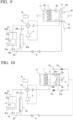
- FIG. 9 is a configuration diagram of a CO 2 adsorption device according to Embodiment 7.
- the CO 2 adsorption device of Embodiment 7 includes a switching valve 14 that switches the flow of the refrigerant in the refrigeration cycle device.
- the switching valve 14 switches the flow direction of the refrigerant in the refrigeration cycle device so that the function of the first heat exchanger 3 and the function of the second heat exchanger 5 are switched between the condenser and the evaporator.
- Embodiment 7 is configured such that the first heat exchanger 3 includes a first heat exchanger 31a and a first heat exchanger 31b.
- the switching valve 14 is described as a four-way valve in FIG. 9 , a configuration in which a plurality of valves are combined may be adopted.
- the first heat exchanger 31a and the first heat exchanger 31b are connected in parallel, and the refrigerant flow path is configured such that the refrigerant flows through the first heat exchanger 31a when functioning as a condenser, and the refrigerant flows through the first heat exchanger 31b when functioning as an evaporator.
- FIG. 9 shows a configuration in which the refrigerant flow path uses check valves 15a and 15b.
- the path between the switching valve 14 and the decompressor 4 is divided into a flow path through the first heat exchanger 31a and a flow path through the first heat exchanger 31b.
- the check valve 15a that allows the refrigerant discharged from the compressor 2 to flow from the switching valve 14 to the decompressor 4 and prevents the refrigerant from flowing in the reverse direction is installed in the flow path through the first heat exchanger 31a.
- the check valve 15b that allows the refrigerant to flow from the decompressor 4 to the switching valve 14 and prevents the refrigerant from flowing in the reverse direction is installed in the flow path through the first heat exchanger 31b.
- the refrigerant flow path may be configured with an opening/closing valve instead of the check valves 15a and 15b.
- the heat discharged from the first heat exchanger 31a which functions as a condenser, is utilized for hot water supply or the like in the same manner as in Embodiment 2.
- the heat supplied to the first heat exchanger 31b, which functions as the evaporator, is provided from the drainage in the same manner as in Embodiment 3.
- the switching valve 14 is basically set such that the second heat exchanger 5 functions as the evaporator.
- the control device 9 allows the second heat exchanger 5 to function as an evaporator, lowering the surface temperature of the second heat exchanger 5 to the temperature below freezing, and performs a dehumidification operation by causing the water vapor in the air flow to adhere to the second heat exchanger 5 as frost.
- the control device 9 allows the refrigeration cycle device to perform the dehumidification operation of an appropriate time and then allows the refrigeration cycle device to perform the defrosting operation to remove the frost adhering to the second heat exchanger 5.
- the control device 9 switches the switching valve 14 to allow the second heat exchanger 5 to function as a condenser, thereby removing the frost adhering to the second heat exchanger 5.
- the second heat exchanger 5 functions as a condenser
- the temperature of the second heat exchanger 5 becomes high, and the frost is rapidly removed, performing the CO 2 adsorption operation well again.
- FIG. 9 shows a configuration in which a temperature sensor 43 is installed downstream of the adsorption material 1 in addition to the temperature sensor 41 upstream of the adsorption material 1.
- the control device 9 may adjust the air flow amount of the temperature-raising operation or may end the temperature-raising operation based on the temperature downstream of the adsorption material 1.
- the refrigeration cycle device makes the second decompressor 7 narrow to allow either one of the second heat exchangers 5a or 5b to function as the condenser while the other second heat exchanger functions as the evaporator. According to this configuration, either of the second heat exchangers 5a or 5b functions as the evaporator and used for dehumidification, while the other second heat exchanger 5a or 5b can be defrosted at the same time.
- the CO 2 adsorption device may be configured to allow the air flow on the downstream side of the adsorption flow path 10 to flow into the desorption flow path 20.
- the CO 2 adsorption device according to any one of Appendices 1 to 3, in which the second heat exchanger is a heat exchanger having fins in which a drainage hole or a drainage slit is formed, or is a finless heat exchanger.
- the CO 2 adsorption device according to any one of Appendices 1 to 4, in which the first heat exchanger is a heat exchanger that performs heat exchange with water.
- the CO 2 adsorption device further including:
- the CO 2 adsorption device further including:
- the CO 2 adsorption device in which the temperature-raising heat exchanger is a heat exchanger that performs heat exchange between the air flow upstream of the second heat exchanger and the air flow downstream of the second heat exchanger.
- the CO 2 adsorption device according to any one of Appendices 1 to 10, further including: a switching valve that switches a flow direction of the refrigerant in the refrigeration cycle device such that a function of the first heat exchanger and a function of the second heat exchanger are switched between a condenser and an evaporator.
- the CO 2 adsorption device in which the control device performs, when the second heat exchanger functions as a condenser, the dehumidification operation of lowering a surface temperature of the second heat exchanger to a temperature below freezing to cause water vapor in the air flow to adhere to the second heat exchanger as frost, and then performs a defrosting operation of allowing the second heat exchanger to function as a condenser to remove the frost adhering to the second heat exchanger.
- the CO 2 adsorption device according to any one of Appendices 1 to 13, further including: a movable shielding member that allows the air flow to pass through the second heat exchanger when the second heat exchanger functions as an evaporator, and that prevents the air flow from passing through the second heat exchanger when the second heat exchanger does not function as the evaporator.
- the CO 2 adsorption device further including: a refrigerant flow path that switches a flow of the refrigerant such that, when a region of the flow path through which the air flow flows is divided into a plurality of regions, the second heat exchanger is divided into a plurality of second heat exchangers such that each of the divided regions is provided with the second heat exchanger, and either one of the divided second heat exchangers functions as an evaporator, the other divided second heat exchanger does not function as an evaporator.
- the CO 2 adsorption device according to the present invention is excellent in terms of energy saving.
Landscapes
- Engineering & Computer Science (AREA)
- Chemical & Material Sciences (AREA)
- Thermal Sciences (AREA)
- Physics & Mathematics (AREA)
- General Engineering & Computer Science (AREA)
- Mechanical Engineering (AREA)
- Chemical Kinetics & Catalysis (AREA)
- Oil, Petroleum & Natural Gas (AREA)
- Analytical Chemistry (AREA)
- General Chemical & Material Sciences (AREA)
- Environmental & Geological Engineering (AREA)
- Biomedical Technology (AREA)
- Health & Medical Sciences (AREA)
- Drying Of Gases (AREA)
- Compression-Type Refrigeration Machines With Reversible Cycles (AREA)
- Treating Waste Gases (AREA)
- Separation Of Gases By Adsorption (AREA)
- Gas Separation By Absorption (AREA)
Abstract
Description
- The present invention relates to a CO2 adsorption device using a solid CO2 adsorption material.
- As a method of reducing the CO2 concentration in the air or recovering CO2 from exhaust gas, a method of using a solid CO2 adsorption material has been known. As the CO2 adsorption material, for example, a granular material in which a substance such as an amine compound that adsorbs CO2 adheres to a surface of a carrier of a porous material is known. Such a solid CO2 adsorption material is utilized for repeatedly adsorbing CO2 by adsorbing CO2 at room temperature or the like and then desorbing CO2 by heating.
- Many solid CO2 adsorption materials are known to have adsorption abilities for gases other than CO2. In a case where moisture (water vapor) in the air is adsorbed on the adsorption material, there is a problem that the adsorption ability of CO2 of the adsorption material is decreased. Therefore, for example, in
Patent Document 1, the moisture is reduced by the moisture adsorption rotor and then the CO2 flows into the CO2 adsorption material so that it is avoided impairing of the adsorption ability of the adsorption material. - Patent Document 1:
Japanese Unexamined Patent Application, First Publication JP 2006- 61 758 A - In the moisture adsorption rotor of
Patent Document 1, a material in which a moisture adsorption material is supported on a base material is used, in the same manner as in the CO2 adsorption material. The moisture adsorption material is heated to desorb moisture and is repeatedly utilized as an adsorption material. However, there is a problem in terms of energy saving because the energy required for heating for the desorption is increased. - Therefore, an object of the present invention is to provide a CO2 adsorption device using a solid CO2 adsorption material, in which a decrease in CO2 adsorption ability is prevented and energy saving is achieved.
- According to the present invention, there is provided a CO2 adsorption device in which a solid adsorption material that adsorbs CO2 is installed in a flow path through which gas flows, the CO2 adsorption device including: a refrigeration cycle device configured to circulate a refrigerant in a compressor, a first heat exchanger, a decompressor, and a second heat exchanger; and a control device configured to control an operation of the refrigeration cycle device, in which the second heat exchanger is installed on an upstream side of an air flow in the flow path with respect to a location where the adsorption material is installed, the refrigeration cycle device performs a dehumidification operation of allowing the second heat exchanger to function as an evaporator to cause moisture contained in the air flow to adhere to a surface of the second heat exchanger, during an adsorption operation of adsorbing CO2, and the CO2 adsorption device further includes a drain flow path that discharges water, which has fallen from the second heat exchanger, to an outside of the flow path, at a lower part of the second heat exchanger.
- In the CO2 adsorption device of the present invention, dehumidification is performed using a heat exchanger that functions as an evaporator of the refrigeration cycle device. Therefore, the energy required for heating, such as a moisture adsorption material, is not necessary. This makes the CO2 adsorption device excellent in preventing a decrease in adsorption ability and in energy saving.
-
-
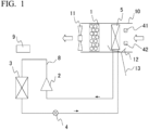
FIG. 1 A configuration diagram of a CO2 adsorption device according toEmbodiment 1. -
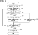
FIG. 2 A flowchart showing an example of control of a CO2 adsorption device according toEmbodiment 1. -
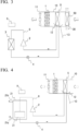
FIG. 3 Aconfiguration diagram of a CO2 adsorption device of a modification example according toEmbodiment 1. -
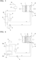
FIG. 4 Aconfiguration diagram of a CO2 adsorption device according toEmbodiment 2. -
FIG. 5 Aconfiguration diagram of a CO2 adsorption device according toEmbodiment 3. -
FIG. 6 Aconfiguration diagram of a CO2 adsorption device according toEmbodiment 4. -
FIG. 7 A configuration diagram of a CO2 adsorption device according toEmbodiment 5. -
FIG. 8 A configuration diagram of a CO2 adsorption device according to Embodiment 6. -
FIG. 9 A configuration diagram of a CO2 adsorption device according toEmbodiment 7. -
FIG. 10 Aconfiguration diagram of a CO2 adsorption device according toEmbodiment 8. -
FIG. 11 A configuration diagram of a CO2 adsorption device according toEmbodiment 9. - Hereinafter, embodiments of the CO2 adsorption device of the present invention will be described with reference to the drawings. It should be noted that the drawings are exemplary examples of the configurations, and the disposition, size, direction, shape, and the like are not limited to the following description and can be appropriately changed. In addition, a part of the configurations disclosed in the following embodiments may be combined with or substituted for the configurations disclosed in other embodiments as long as there is no contradiction.
-
FIG. 1 is a configuration diagram of a CO2 adsorption device according toEmbodiment 1. The CO2 adsorption device is a CO2 adsorption device in which asolid adsorption material 1 that adsorbs CO2 is installed in a flow path through which a gas flows. Theadsorption material 1 is installed in anadsorption flow path 10, such as a duct, and theadsorption flow path 10 is configured to generate an air flow by ablower 11. The white arrows inFIG. 1 indicate the flow of the air flow. In theadsorption flow path 10, it is not always necessary to have theblower 11 when the air flow is generated, and when theblower 11 is installed, theblower 11 may be installed on either the upstream side or the downstream side of theadsorption material 1. Theadsorption material 1 is installed to cover the entire flow path cross section of theadsorption flow path 10 such that theadsorption material 1 can be in contact with the entire air flow flowing through theadsorption flow path 10. - The gas that flows into the
adsorption flow path 10 and is the target of the CO2 adsorption is a gas including CO2 and water vapor, and may include other gases such as air. The target gas is, for example, a gas having a relatively high CO2 concentration, such as a combustion gas from a boiler or a gas emitted from alcohol fermentation, or a gas having a relatively low CO2 concentration, such as outside air taken into a building for ventilating a room or air taken into a duct from indoors. - The
adsorption material 1 is, for example, a material accommodating a particle of a porous material in a container in which air circulates inside and outside. A substance such as an amine compound that adsorbs CO2 adheres to the surface of the particle. Since the substance that adsorbs CO2 is a solid, the substance is described as a solid adsorption material in the present invention. The substance that adsorbs CO2 may be integrated with the container by being fixed to the surface of a member such as a metal, a resin, or ceramics, in addition to being accommodated in the container. - The amount of CO2 that can be adsorbed by the
adsorption material 1 has an upper limit, and theadsorption material 1 that has adsorbed CO2 can desorb the adsorbed CO2 by heating, and can adsorb CO2 again. Theadsorption material 1 may adsorb not only CO2 but also water vapor, and is preferable to reduce the water vapor from the target gas before the adsorption of CO2. - The air flow in the
adsorption flow path 10 comes into contact with the substance in theadsorption material 1 and flows. In this case, CO2 is adsorbed on this substance, so that the CO2 concentration on the downstream side of theadsorption material 1 is lower than the CO2 concentration on the upstream side of theadsorption material 1. When CO2 is adsorbed until theadsorption material 1 approaches the upper limit value in which CO2 can be adsorbed, the adsorption ability is decreased. - It is preferable to replace the
adsorption material 1 with sufficient adsorption ability for each appropriate time when the adsorption amount approaches the upper limit value. Although the example of theadsorption material 1 being left to stand in theadsorption flow path 10 is shown inFIG. 1 , for example, a rotor-type adsorption material 1 that alternately repeats adsorption and desorption through rotation, as described in the prior art, may also be used. - The CO2 adsorption device includes a vapor compression type refrigeration cycle device in which a
compressor 2, afirst heat exchanger 3, adecompressor 4, and asecond heat exchanger 5 are connected to each other by apipe 8 such that a refrigerant circulates. The operation state of thecompressor 2, thedecompressor 4, and the like in the refrigeration cycle device is controlled by acontrol device 9. In the refrigeration cycle device, the refrigerant is sucked into thecompressor 2 in a gas state, compressed into a high-temperature and high-pressure gas, and discharged. The refrigerant then condenses in thefirst heat exchanger 3, which functions as a condenser, into a liquid state. - Subsequently, the refrigerant is decompressed in the
decompressor 4 into a low-temperature and low-pressure refrigerant. As the refrigerant, it is desirable to use a hydrofluorolefin with a global warming potential (GWP) of 10 or less, a hydrocarbon, or CO2 as the main component. The refrigerant evaporates in thesecond heat exchanger 5, which functions as the evaporator, into a gas and is then sucked into thecompressor 2 again. Arrows inFIG. 1 indicate the direction in which the refrigerant flows. The heat exchanger that functions as a condenser discharges heat to the outside, and the heat exchanger that functions as an evaporator absorbs heat from the outside. Thecontrol device 9 adjusts the surface temperatures of thefirst heat exchanger 3 and thesecond heat exchanger 5 by operating thecompressor 2, adjusting the opening degree of thedecompressor 4, or the like. - The
second heat exchanger 5 is installed on the upstream side of the air flow from the location where theadsorption material 1 is installed in theadsorption flow path 10. The refrigeration cycle device is operated such that thesecond heat exchanger 5 functions as the evaporator, and thesecond heat exchanger 5 performs heat exchange with the air flow in theadsorption flow path 10. In the refrigeration cycle device, the type and pressure of the refrigerant are selected such that the surface temperature of thesecond heat exchanger 5, which functions as the evaporator, is sufficiently lower than the temperature of the upstream air flow. The refrigeration cycle device cools the moisture (water vapor) included in the air flow in theadsorption flow path 10, condensing the moisture into liquid water on the surface of thesecond heat exchanger 5 or causing the moisture to adhere as solid frost, thereby performing dehumidification. - In a case where the temporal variation in the flow velocity, temperature, humidity, or the like of the air flow flowing into the
adsorption flow path 10 is small, the refrigeration cycle device may be operated under fixed conditions without performing control based on the temperature and humidity of the air flow. However, in a case where the temperature and humidity of the air flow vary, even when the air flow in theadsorption flow path 10 is cooled, the air flow may not be dehumidified unless the temperature of thesecond heat exchanger 5 is equal to or lower than the saturation temperature of the water vapor in the air flow. Therefore, it is desirable that thecontrol device 9 controls the operation of thecompressor 2, thedecompressor 4, and the like so that the dehumidification operation is performed by the refrigeration cycle device, whereby thesecond heat exchanger 5 reaches an appropriate temperature based on the temperature and humidity of the air flow upstream of thesecond heat exchanger 5. -
FIG. 1 shows an example in which atemperature sensor 41 and ahumidity sensor 42 are installed on the upstream side of thesecond heat exchanger 5 in the air flow to measure the temperature and humidity of the air flow that flows into theadsorption flow path 10. Thetemperature sensor 41 and thehumidity sensor 42 do not need to be installed in theadsorption flow path 10. - In addition, in a case where the temperature and humidity of the air flow flowing into the
adsorption flow path 10 can be measured or estimated by another means, thecontrol device 9 may perform controls based on information thereof. Although thetemperature sensor 41 and thehumidity sensor 42 are shown inFIG. 1 , thetemperature sensor 41 and thehumidity sensor 42 may be omitted for simplicity in the following embodiments. - In the
second heat exchanger 5, for example, fins are attached to a heat transfer pipe through which the refrigerant flows, thereby increasing the heat exchange area between the refrigerant and the air. The fins are installed with intervals therebetween such that the air flow in theadsorption flow path 10 flows from the upstream side to the downstream side, and preferably have a shape and structure that allows water adhering to the surface of the fins to be easily drained by gravity. For example, thesecond heat exchanger 5 may be a circular pipe heat exchanger, a finless heat exchanger, or the like. In addition, it is preferable that thesecond heat exchanger 5 is a heat exchanger having fins with a drainage hole formed. In particular, in a flat pipe heat exchanger using corrugated fins, it is preferable that a louver slit for improving contact with the air flow is formed, and it is also preferable that a drainage hole and a drainage slit are formed in addition to the louver slit. - In addition, the finless heat exchanger has an excellent drainage property because there are no fins to which water is likely to adhere. The
second heat exchanger 5 may be a heat exchanger with a surface made of a water-repellent material such as a fluorine compound. Thesecond heat exchanger 5 may have a structure in which the fins joined to the heat transfer pipes extend from the heat transfer pipes to the upstream side of the air flow, but do not extend to the downstream side of the air flow or extend less on the downstream side of the air flow than on the upstream side of the air flow. Thesecond heat exchanger 5 is installed to cover the entire flow path cross section of theadsorption flow path 10 so that thesecond heat exchanger 5 can be in contact with the entire air flow flowing through theadsorption flow path 10. - A
drain pan 12 that receives the water flowing down from thesecond heat exchanger 5 and adrain pipe 13 that discharges the water received by thedrain pan 12 to the outside of theadsorption flow path 10 are connected to each other at a lower part of thesecond heat exchanger 5. Thedrain pan 12 and thedrain pipe 13 are drain flow paths discharging the water that has fallen from thesecond heat exchanger 5 to the outside of theadsorption flow path 10. - It is preferable that the
drain pan 12 has a structure in which the fallen water does not flow to theadsorption material 1 side. When water accumulates on the downstream side of thesecond heat exchanger 5, the water accumulated in thedrain pan 12 may re-evaporate due to the air flow in theadsorption flow path 10, potentially reducing the dehumidification effect toward theadsorption material 1 side. - Therefore, for example, as shown in
FIG. 1 , the bottom of thedrain pan 12 preferably may be inclined or provided with a step such that the downstream side of the bottom of the drain pan 12 (adsorption material 1 side) becomes higher and the windward side becomes lower, whereby the water falling from thesecond heat exchanger 5 flows to the upstream side of thesecond heat exchanger 5 and is accumulated. In addition, the upper part of the downstream side of thesecond heat exchanger 5 of thedrain pan 12 may be covered with a cover (not shown) or the like. - In addition, since the performance of the
adsorption material 1 significantly deteriorates when water adheres to theadsorption material 1, theadsorption material 1 and thesecond heat exchanger 5 are installed with an interval therebetween to prevent water adhering to thesecond heat exchanger 5 from adhering to theadsorption material 1. The extending direction of theadsorption flow path 10 is not particularly limited, but it is desirable that thesecond heat exchanger 5 is not directly above theadsorption material 1 and is positioned to be deviated horizontally so that water does not fall from thesecond heat exchanger 5 to theadsorption material 1. In addition, in order to prevent water carried by the air flow from thesecond heat exchanger 5 from adhering to theadsorption material 1, a louver or the like may be installed between thesecond heat exchanger 5 and theadsorption material 1. -
FIG. 2 is a flowchart showing an example of the control of the CO2 adsorption device. When the control is started, first, an air flow is generated in theadsorption flow path 10 by operating theblower 11 or the like (step S1). It should be noted that, in a case where theadsorption flow path 10 is always a flow path in which an air flow is generated, the step S1 may be omitted. In addition, in a case where theadsorption flow path 10 is a flow path in which an air flow is generated intermittently, the generation of the air flow may be confirmed as step S1. Next, the temperature and humidity of the air flow flowing into theadsorption flow path 10 are measured (step S2). Then, thecontrol device 9 controls the operation of the refrigeration cycle device based on the temperature and humidity of the air flow upstream of the second heat exchanger obtained in step S2. - The
control device 9 confirms whether the temperature and humidity of the air flow are within a valid range for dehumidification using the refrigeration cycle device (step S3). In a case where the humidity is lower than a predetermined value (for example, less than the relative humidity of 20 %), or the temperature is lower than a predetermined value, or the relationship between the temperature and humidity does not satisfy a certain relationship, the dehumidification operation is not performed (step S6). - On the other hand, when the temperature and humidity are within the valid range, the dehumidification operation is performed. In this case, the temperature of the surface of the
second heat exchanger 5 is set to be lower than the temperature at which the water vapor in the air flow becomes saturated water vapor, based on the values of the temperature and humidity (step S4). - In a case where the temperature of the
second heat exchanger 5 is significantly lowered even when the humidity is low, dehumidification is possible, but the amount of water that can be dehumidified with respect to the electric power required for the refrigeration cycle device is small, resulting in low dehumidification efficiency. In addition, when the temperature is low, the amount of water contained in the air flow is small, resulting in low dehumidification efficiency. - In these conditions, even when the refrigeration cycle device does not perform dehumidification, the decrease in adsorption ability of the
adsorption material 1 is suppressed because the humidity is low. In addition, since the refrigeration cycle device does not perform the dehumidification operation under such conditions, energy saving is achieved. - In a case where the temperature and humidity of the air flow flowing into the
adsorption flow path 10 are high, the water vapor in the air flow can condense into water to be dehumidified. For example, in a case where the temperature of the air flow flowing into theadsorption flow path 10 is sufficiently higher than 0 °C (for example, 15 °C or higher) and the humidity is high (for example, the relative humidity of 50 % or higher), the temperature of thesecond heat exchanger 5 can be set to, for example, 0 °C to 5 °C to perform dehumidification. - On the other hand, in a case where the temperature and humidity of the air flow are low, the water vapor in the air flow can be dehumidified by converting the water vapor into ice (frost). For example, in a case where the temperature of the air flow flowing into the
adsorption flow path 10 is 5 °C or lower, or the relative humidity is less than 30 %, the temperature of thesecond heat exchanger 5 is set to a temperature lower than 0 °C, for example, -10 °C to -5 °C, and the water vapor in the air flow adheres to thesecond heat exchanger 5 as frost, resulting in dehumidification. It should be noted that in a case where the temperature and humidity are in the intermediate range thereof, whether the dehumidification is performed as condensed water or as frost may be determined based on a predetermined condition table or the like. - The refrigeration cycle device performs the dehumidification operation based on the operating conditions obtained in step S4 (step S5). It is determined whether a signal of a command for ending the adsorption operation from the outside is input for each unit time (for example, 10 seconds) during the dehumidification operation of step S5 or during the stop of the dehumidification operation of step S6 (step S7). In a case where it is determined that the end command is input in step S7, the operation related to the dehumidification operation is stopped (step S8), and the adsorption operation is ended. In a case where the end command is not input, the process returns to step S2 again, the temperature and humidity are measured. Subsequently, the operating conditions are reviewed as in S4 to S6.
- In the dehumidification operation of step S5, in a case where dehumidification is performed by adhering frost to the
second heat exchanger 5, when the amount of frost adhering to thesecond heat exchanger 5 increases, the air flow becomes difficult to flow through. Therefore, thecontrol device 9 allows the refrigeration cycle device to perform a defrosting operation to remove the frost regularly. In general, during the defrosting operation, the temperature of thesecond heat exchanger 5 is raised, melting the frost adhering to thesecond heat exchanger 5 and causing the frost to fall as water. - The defrosting operation may stop the refrigeration cycle device and raise the temperature of the
second heat exchanger 5. In addition, it is preferable to stop the air flow in theadsorption flow path 10 during the dehumidification operation so that the water evaporated from the water flowing through thesecond heat exchanger 5 is not directed to the adsorption material. In addition, when it is difficult to perform the dehumidification operation, the dehumidification operation may be performed only under the condition of dehumidifying as condensed water. - As described above, the CO2 adsorption device of
Embodiment 1 removes the water vapor by using the heat exchanger that functions as the evaporator of the refrigeration cycle device. In a configuration in which the moisture adsorption material is used for dehumidification as in the related art, since the moisture and the moisture adsorption material are strongly bonded to each other, the energy required for desorption is increased, which is a problem in terms of energy saving. - As in
Embodiment 1, in a configuration in which cooling and dehumidification are performed by the evaporator, the water generated by the dehumidification can be easily discharged, and the configuration is excellent in terms of preventing the decrease in CO2 adsorption ability and energy saving. In addition, when the CO2 adsorption device includes thecontrol device 9 that controls the operation of the refrigeration cycle device based on the temperature and humidity of the air flow upstream of thesecond heat exchanger 5, it is possible to further reduce the energy required for dehumidification. - In addition, the dehumidification configuration of
Embodiment 1 may be combined with a dehumidification configuration using a moisture adsorption material. It is possible to perform dehumidification by the refrigeration cycle device on the upstream side of the moisture adsorption material, and reduce the energy required for regenerating the moisture adsorption material due to the decrease of the amount of moisture adsorbed by the moisture adsorption material. -
FIG. 3 is a configuration diagram of a CO2 adsorption device of a modification example according toEmbodiment 1. In the CO2 adsorption device of the modification example, a stationary typetotal heat exchanger 50 is installed on the upstream side of theadsorption flow path 10 with respect to thesecond heat exchanger 5. Thetotal heat exchanger 50 is connected to aventilation flow path 30 through which an air flow different from the air flow flowing into theadsorption flow path 10 flows. Thetotal heat exchanger 50 performs total heat exchange between the air flow flowing into theadsorption flow path 10 and the air flow flowing through theventilation flow path 30. - A typical stationary type
total heat exchanger 50 has a structure in which flow paths, partitioned by sheets and independent of each other, are alternately stacked. Since the sheets have both heat transfer properties and moisture permeability, thetotal heat exchanger 50 can continuously perform both sensible heat exchange and latent heat exchange between the two air flows. Since such a stationary typetotal heat exchanger 50 does not require power, energy-saving heat exchange can be achieved. By allowing an air flow with lower humidity than that in theadsorption flow path 10 to flow through theventilation flow path 30, the humidity of the air flow flowing into theadsorption flow path 10 can be lowered. Therefore, in the CO2 adsorption device of the modification example, the load of dehumidification by thesecond heat exchanger 5 is reduced, resulting in energy saving. -
FIG. 4 is a configuration diagram of a CO2 adsorption device according toEmbodiment 2. The CO2 adsorption device ofEmbodiment 2 is afirst heat exchanger 31 that performs heat exchange with water, which functions as the condenser of the CO2 adsorption device ofEmbodiment 1. The heat exchanger that performs heat exchange with water has better heat exchange performance and is easier to reduce the size of the heat exchanger than a heat exchanger that performs heat exchange with gas. In the heat exchanger that performs heat exchange with water, a flow of water is also required, but the efficiency of heat exchange is better than that of a gas, and heat exchange utilizing water convection or the like is also effective. - Therefore, it is possible to reduce the energy required for allowing the fluid to flow. In addition, when combined with a facility that utilizes water, the pressure of the water supply can be utilized to generate the flow of water, thereby saving the electric power required for generating the water flow. In the present invention, a liquid in which the main component is water is described as water, even when inorganic substances or organic substances are dissolved in the liquid or non-dissolved substances are mixed in a flowable manner in the liquid.
- The CO2 adsorption device shown in
FIG. 4 includes acontainer 21 that allows inflow and outflow of water and stores water, and thefirst heat exchanger 31 is a heat source that heats the water stored in thecontainer 21. Thefirst heat exchanger 31 is a heat exchanger that functions as a condenser during the dehumidification operation described as thefirst heat exchanger 3 in the above-described embodiment. - In the
first heat exchanger 31, for example, fins are attached to a heat transfer pipe through which the refrigerant flows, thereby increasing the heat exchange area between the refrigerant and the water. In addition, thefirst heat exchanger 31 may have a structure in which the flow path through which the refrigerant flows and the flow path through which the water flows are partitioned by a plate for heat exchange. - It is not essential but preferable that the
container 21 is a part of hot water supply equipment that supplies hot water inside a building. Thecontainer 21 is provided with aninflow port 21a at the lower part for cold water to flow in and anoutflow port 21b at the upper part for heated water (hot water) to flow out, and thefirst heat exchanger 31 is installed at the lower part inside thecontainer 21. Thecontainer 21 is filled with water. The cold water flowing in from theinflow port 21a is heated by thefirst heat exchanger 31 and flows out from theoutflow port 21b as hot water. - The water may be heated when the water is not flowing in from the
inflow port 21a. In that case, convection occurs in the water heated by thefirst heat exchanger 31, thereby heating the water in thecontainer 21. In addition, when thecontainer 21 has an appropriate heat insulating property, the heat of the heated water does not immediately decrease. Therefore, the water can store heat as hot water. The heated water (hot water) flowing out from thecontainer 21 can be utilized as hot water for bath, room heating, or the like. The water in thecontainer 21 may be utilized as another heat source without being directly utilized as water. - In addition, the
first heat exchanger 31 may be configured to discharge heat to water during the dehumidification operation in which thesecond heat exchanger 5 functions as an evaporator, and it is not always necessary to utilize the discharged heat of thefirst heat exchanger 31 during the dehumidification operation. For example, in a configuration where the refrigeration cycle device includes another heat exchanger (not shown) connected in parallel with thesecond heat exchanger 5 and either of the heat exchangers can be switched to function as an evaporator, the discharged heat of thefirst heat exchanger 31 may be utilized when the other heat exchanger functions the evaporators. - Similarly, it is not always necessary to utilize the discharged heat of the
first heat exchanger 31 to heat water during the dehumidification operation of thesecond heat exchanger 5. For example, the refrigeration cycle device may include another heat exchanger (not shown) in parallel with thefirst heat exchanger 31, and may be configured to switch the other heat exchanger to function as a condenser during the dehumidification operation of thesecond heat exchanger 5. - As described above, the CO2 adsorption device of
Embodiment 2 uses thefirst heat exchanger 31, which functions as a condenser, as a heat exchanger that performs heat exchange with water. Therefore, it is possible to reduce the energy required for generating the flow in the fluid that performs heat exchange with the refrigerant of the refrigeration cycle, thereby achieving energy saving. In addition, since the hot water supply equipment that supplies hot water inside the building is configured using thecontainer 21 that allows the inflow and outflow of water and stores water, and the heat discharged from thefirst heat exchanger 31 during the dehumidification operation can be effectively utilized, it is effective in energy saving. -
FIG. 5 is a configuration diagram of a CO2 adsorption device according toEmbodiment 3. The CO2 adsorption device ofEmbodiment 3 is thefirst heat exchanger 31 that performs heat exchange with water, which functions as a condenser, in the same manner as the CO2 adsorption device ofEmbodiment 2. The condenser of the CO2 adsorption device ofEmbodiment 3 performs heat exchange with drained water ofwater utilization equipment 27. - The
water utilization equipment 27 is, for example, a device that cools heat-generating components using cooling water or cleaning equipment that utilizes water. The water that has entered thewater utilization equipment 27 from thewater supply pipe 24 is drained through adrainage pipe 25 after utilization. Thefirst heat exchanger 31 can be a heat exchanger in which a refrigerant pipe is wound around thedrainage pipe 25, or a heat exchanger placed inside a drainage tank similar to the container inEmbodiment 3, so that thefirst heat exchanger 31 performs heat exchange with the water in thedrainage pipe 25. The drained water heated by thefirst heat exchanger 31 is guided to drainage treatment equipment outside the building. - The CO2 adsorption device of
Embodiment 4 uses thefirst heat exchanger 31, which functions as a condenser, as a heat exchanger that performs heat exchange with water. Therefore, it is possible to reduce the energy required for generating the flow in the fluid that performs heat exchange with the refrigerant of the refrigeration cycle, thereby achieving energy saving. In addition, since the flow of the water is generated by the pressure of the water entering thewater utilization equipment 27, it is possible to save energy for allowing the water to flow. -
FIG. 6 is a configuration diagram of a CO2 adsorption device according toEmbodiment 5. In addtion to the CO2 adsorption devices of the above-described embodiments, the CO2 adsorption device ofEmbodiment 5 further includes a temperature-raisingheat exchanger 16, in which a fluid having a temperature higher than the temperature of the refrigerant flowing through thesecond heat exchanger 5 flows, between thesecond heat exchanger 5 and theadsorption material 1. The temperature-raisingheat exchanger 16 is located on the downstream side of thesecond heat exchanger 5 in the air flow of theadsorption flow path 10 and is located on the upstream side of theadsorption material 1. The temperature-raisingheat exchanger 16 performs heat exchange between the air flow that is cooled during dehumidification in thesecond heat exchanger 5 and the fluid that flows inside the temperature-raisingheat exchanger 16, thereby raising the temperature of the air flow that passes through the temperature-raisingheat exchanger 16 and flows toward theadsorption material 1. - The fluid flowing inside the temperature-raising
heat exchanger 16 may be, for example, the water in thecontainer 21 described inEmbodiment 2, the drained water described inEmbodiment 3, additionally, a heat generating device or exhaust gas, and may also be configured as embodiments in the following description. It is desirable that the temperature-raisingheat exchanger 16 has a heat discharge amount sufficient to raise the temperature of the air flow toward theadsorption material 1 to the same extent as the air flow that flows into theadsorption flow path 10. - However, when the temperature of the air flow toward the
adsorption material 1 becomes excessively high, there is a concern that the adsorption performance of theadsorption material 1 may deteriorate. The temperature of the air flow toward theadsorption material 1 may be set to a temperature between the temperature of the air flow flowing into theadsorption flow path 10 and the temperature of the air flow immediately downstream of thesecond heat exchanger 5.FIG. 6 shows a configuration in which the water in thecontainer 21 is heated by thefirst heat exchanger 31 that functions as a condenser, in the same manner as inEmbodiment 2, and the temperature of the air flow toward theadsorption material 1 may be appropriately increased by allowing some of the water in thecontainer 21 to flow into the temperature-raisingheat exchanger 16. - The CO2 adsorption ability of the
adsorption material 1 is improved by cooling the air flow, but the moisture absorbing amount may be increased at the same time. Therefore, by increasing the temperature of the air flow, the relative humidity can be lowered, and moisture absorption can be suppressed. As a result, it is possible to prevent the moisture absorption of theadsorption material 1 and to improve the CO2 adsorption ability with respect to the moisture absorption. - In addition, when the temperature of the air flow is lowered, the temperature of the
adsorption material 1 is also lowered. In a case where the operation of CO2 adsorption is stopped, when theadsorption material 1 is also maintained at a low temperature, there is a concern that theadsorption material 1 may deteriorate due to condensation. According to the CO2 adsorption device ofEmbodiment 5, the temperature of the air flow cooled when dehumidified by thesecond heat exchanger 5 is raised by the temperature-raisingheat exchanger 16, so that the CO2 adsorption ability can be improved, or the deterioration of theadsorption material 1 can be prevented. -
FIG. 7 is a configuration diagram of a CO2 adsorption device according toEmbodiment 5. The CO2 adsorption device ofEmbodiment 5 is configured such that the temperature-raisingheat exchanger 16 of the CO2 adsorption device ofEmbodiment 4 is used as aheat exchanger 26 that performs heat exchange between the air flow to be adsorbed with CO2 and the air flow after dehumidification by thesecond heat exchanger 5. The air flow to be adsorbed with CO2 is guided to theheat exchanger 26 in aflow path 34 and is heat-exchanged with the air flow downstream of thesecond heat exchanger 5 by theheat exchanger 26. - The air flow that flows through the
heat exchanger 26 from theflow path 34 is guided upstream of thesecond heat exchanger 5 in theadsorption flow path 10 through aflow path 35. That is, theheat exchanger 26 performs heat exchange between the air flow upstream of thesecond heat exchanger 5 and the air flow downstream of thesecond heat exchanger 5. As theheat exchanger 26, for example, a heat exchanger, in which the air flow downstream of thesecond heat exchanger 5 and the air flow passing through the inside of theheat exchanger 16 are partitioned by a thin plate, can be used. - In
Embodiment 5, theheat exchanger 26 is cooled by the air flow downstream of thesecond heat exchanger 5, which potentially cause condensation inside theheat exchanger 16. Theheat exchanger 16 may include a drainage path (not shown) for discharging the condensed water generated inside to the outside. - According to the CO2 adsorption device of
Embodiment 5, the temperature of the air flow cooled when dehumidified by thesecond heat exchanger 5 is raised by theheat exchanger 26, in the same manner as inEmbodiment 4, so that the CO2 adsorption ability can be improved, or the deterioration of theadsorption material 1 can be prevented. In addition, since the air flow guided into the inside of theheat exchanger 16 is generated by the air flow flowing through theadsorption flow path 10, it is not necessary to provide a blower or the like, resulting in energy saving. -
FIG. 8 is a configuration diagram of a CO2 adsorption device according to Embodiment 6. The CO2 adsorption device of Embodiment 6 is configured such that the temperature-raisingheat exchanger 16 ofEmbodiment 4 is used as the third heat exchanger 6 through which the refrigerant of the refrigeration cycle device flows. The third heat exchanger 6 is connected to thepipe 8 between thefirst heat exchanger 31 and thesecond heat exchanger 5. In addition, asecond decompressor 7 is provided between the third heat exchanger 6 and thesecond heat exchanger 5. AlthoughFIG. 8 shows a configuration of thefirst heat exchanger 31 in which the heat exchanger, which functions as a condenser, performs heat exchange with water in thecontainer 21, the heat exchanger may be thefirst heat exchanger 3 in which the condenser performs heat exchange with the air flow. - The refrigerant that is discharged from the
compressor 2 and flows from thefirst heat exchanger 31 to the third heat exchanger 6 is decompressed by thesecond decompressor 7 and flows to thesecond heat exchanger 5. When the pressure of the refrigerant flowing into the third heat exchanger 6 is kept higher than the pressure of the refrigerant flowing into thesecond heat exchanger 5 by thesecond decompressor 7, the temperature of the third heat exchanger 6 can be made higher than the temperature of thesecond heat exchanger 5. As a result, the air flow that had passed through thesecond heat exchanger 5 and that had been cooled can be heated by the third heat exchanger 6 and directed to theadsorption material 1. - With such a configuration, the third heat exchanger 6 functions as a condenser, and the air flow can be heated by the heat generated when the refrigerant condenses. In addition, even when the refrigerant does not condense, the temperature of the third heat exchanger 6 is higher than the temperature of the
second heat exchanger 5. Therefore, the air flow that had passed through thesecond heat exchanger 5 and that had been cooled can be heated. - In addition, when the
second decompressor 7 is configured such that the opening degree of a valve through which the refrigerant flows is variable, or such that a flow path with a narrowed opening degree and a flow path with an un-narrowed opening degree can be switched, it is preferable because the temperature of the third heat exchanger 6 can be adjusted. With this configuration, the third heat exchanger 6 can also be utilized for dehumidification in the same manner as in thesecond heat exchanger 5 by using the third heat exchanger 6 as the evaporator without performing the decompression by thesecond decompressor 7. - The refrigeration cycle device may be controlled to switch between adjusting the decompression of the
second decompressor 7 according to the temperature and humidity of the air flow to lower the temperature of the third heat exchanger 6 for the purpose of dehumidification, or using the third heat exchanger 6 to heat the air flow after dehumidification by thesecond heat exchanger 5. - According to the CO2 adsorption device of Embodiment 6, the temperature of the air flow cooled when dehumidified by the
second heat exchanger 5 is raised by the third heat exchanger 6, in the same manner as inEmbodiment 4, so that the CO2 adsorption ability can be improved, or the deterioration of theadsorption material 1 can be prevented. In addition, since the temperature of the third heat exchanger 6 can be adjusted by thesecond decompressor 7, the function of the third heat exchanger 6 can be changed depending on the situation. -
FIG. 9 is a configuration diagram of a CO2 adsorption device according toEmbodiment 7. The CO2 adsorption device ofEmbodiment 7 includes a switchingvalve 14 that switches the flow of the refrigerant in the refrigeration cycle device. The switchingvalve 14 switches the flow direction of the refrigerant in the refrigeration cycle device so that the function of thefirst heat exchanger 3 and the function of thesecond heat exchanger 5 are switched between the condenser and the evaporator. It should be noted thatEmbodiment 7 is configured such that thefirst heat exchanger 3 includes afirst heat exchanger 31a and afirst heat exchanger 31b. Although the switchingvalve 14 is described as a four-way valve inFIG. 9 , a configuration in which a plurality of valves are combined may be adopted. - The
first heat exchanger 31a and thefirst heat exchanger 31b are connected in parallel, and the refrigerant flow path is configured such that the refrigerant flows through thefirst heat exchanger 31a when functioning as a condenser, and the refrigerant flows through thefirst heat exchanger 31b when functioning as an evaporator. As an example,FIG. 9 shows a configuration in which the refrigerant flow path usescheck valves valve 14 and thedecompressor 4 is divided into a flow path through thefirst heat exchanger 31a and a flow path through thefirst heat exchanger 31b. Thecheck valve 15a that allows the refrigerant discharged from thecompressor 2 to flow from the switchingvalve 14 to thedecompressor 4 and prevents the refrigerant from flowing in the reverse direction is installed in the flow path through thefirst heat exchanger 31a. Thecheck valve 15b that allows the refrigerant to flow from thedecompressor 4 to the switchingvalve 14 and prevents the refrigerant from flowing in the reverse direction is installed in the flow path through thefirst heat exchanger 31b. The refrigerant flow path may be configured with an opening/closing valve instead of thecheck valves - The heat discharged from the
first heat exchanger 31a, which functions as a condenser, is utilized for hot water supply or the like in the same manner as inEmbodiment 2. The heat supplied to thefirst heat exchanger 31b, which functions as the evaporator, is provided from the drainage in the same manner as inEmbodiment 3. By separating thefirst heat exchanger 31a through which the refrigerant flows when functioning as a condenser, and thefirst heat exchanger 3 1b through which the refrigerant flows when functioning as an evaporator, the heat discharged from thefirst heat exchanger 31a can be efficiently utilized. - Next, the operation according to
Embodiment 7 will be briefly described. In the adsorption operation where CO2 is adsorbed in the same manner as inEmbodiment 1, the switchingvalve 14 is basically set such that thesecond heat exchanger 5 functions as the evaporator. Thecontrol device 9 allows thesecond heat exchanger 5 to function as an evaporator, lowering the surface temperature of thesecond heat exchanger 5 to the temperature below freezing, and performs a dehumidification operation by causing the water vapor in the air flow to adhere to thesecond heat exchanger 5 as frost. - The
control device 9 allows the refrigeration cycle device to perform the dehumidification operation of an appropriate time and then allows the refrigeration cycle device to perform the defrosting operation to remove the frost adhering to thesecond heat exchanger 5. Thecontrol device 9 switches the switchingvalve 14 to allow thesecond heat exchanger 5 to function as a condenser, thereby removing the frost adhering to thesecond heat exchanger 5. In a case where thesecond heat exchanger 5 functions as a condenser, the temperature of thesecond heat exchanger 5 becomes high, and the frost is rapidly removed, performing the CO2 adsorption operation well again. In the case of performing the defrosting operation, it is preferable that theblower 11 is stopped. - In addition, the
control device 9 may allow thesecond heat exchanger 5 to function as a condenser after the dehumidification operation, in which thesecond heat exchanger 5 functions as an evaporator, is ended, and may perform a temperature-raising operation to raise the temperature of theadsorption material 1 cooled by the dehumidification operation. In this case, while frost and water adhere to the surface of thesecond heat exchanger 5, the air flow is not allowed to flow. After the temperature of the surface of thesecond heat exchanger 5 reaches a temperature of the air flow that can be sufficiently raised in theadsorption flow path 10, the air flow is allowed to flow toward theadsorption material 1. - The temperature of the
second heat exchanger 5 is adjusted such that the raised temperature of theadsorption material 1 is sufficiently lower than the temperature required for desorbing CO2 from theadsorption material 1. Theadsorption material 1, which is cooled during the dehumidification operation, is heated by the air flow that has been heated. In conditions where the amount of water vapor in the air flow is large, there is a concern of condensation on the surface of theadsorption material 1 even when using the heated air flow. Therefore, the humidity of the air flow may be confirmed with thehumidity sensor 42, and the temperature-raising operation may be performed when the humidity is equal to or lower than a predetermined level. - In a case where such a temperature-raising operation is not performed, after the dehumidification operation is ended, the
adsorption material 1 performs heat exchange with the surrounding gas and the temperature of theadsorption material 1 gradually approaches the temperature of the surrounding gas. However, when the humidity of the surrounding gas varies, condensation may occur on the surface of theadsorption material 1, leading to potential deterioration of theadsorption material 1. Since theadsorption material 1 is heated using the heated air flow, it is possible to prevent deterioration due to condensation. -
FIG. 9 shows a configuration in which atemperature sensor 43 is installed downstream of theadsorption material 1 in addition to thetemperature sensor 41 upstream of theadsorption material 1. Thecontrol device 9 may adjust the air flow amount of the temperature-raising operation or may end the temperature-raising operation based on the temperature downstream of theadsorption material 1. - In addition, the CO2 adsorption device shown in
FIG. 9 includes adamper 19 between thesecond heat exchanger 5 and theadsorption material 1. Thedamper 19 is a movable shielding member that is switched to allow or prevent the air flow from thesecond heat exchanger 5 toward theadsorption material 1. Thedamper 19 may perform an opening/closing operation by attaching a shielding plate to a rotation shaft and rotating the rotation shaft, or thedamper 19 may perform an opening/closing operation by the shielding plate being slid. Thedamper 19 is opened when thesecond heat exchanger 5 functions as the evaporator, allowing the air flow to pass through thesecond heat exchanger 5 and being directed to theadsorption material 1. - Therefore, the
damper 19 is closed when thesecond heat exchanger 5 does not function as an evaporator, preventing the air flow from passing through thesecond heat exchanger 5 and being directed to theadsorption material 1. The case where thesecond heat exchanger 5 does not function as the evaporator refers to the case where thesecond heat exchanger 5 functions as the condenser, or the case where the refrigeration cycle device is stopped, or the like. The surface of thesecond heat exchanger 5 may be dry, but when thesecond heat exchanger 5 functions as the condenser while water adheres thereto, water vapor is generated. - When this water vapor flows into the
adsorption material 1, there is a concern that the performance of theadsorption material 1 may deteriorate. In addition, when the refrigeration cycle device is stopped, there is a concern that the performance of theadsorption material 1 may deteriorate when a high-humidity air flow flows through theadsorption flow path 10. Therefore, thedamper 19 is closed to prevent high-humidity air flow from flowing to theadsorption material 1. It should be noted that, even in a case where the switchingvalve 14 that switches the flow of the refrigerant of the refrigeration cycle device is not provided, as inEmbodiment 1, the air flow may be prevented from flowing when the refrigeration cycle device is stopped by the shielding member. -
FIG. 10 is a configuration diagram of a CO2 adsorption device according toEmbodiment 8. The CO2 adsorption device ofEmbodiment 8 has a configuration in which thesecond heat exchanger 5 installed in theadsorption flow path 10 is divided into a plurality ofsecond heat exchangers 5. In the CO2 adsorption device ofEmbodiment 8, a region of theadsorption flow path 10 through which the air flow flows is divided into a plurality of regions, and thesecond heat exchanger 5 is divided into a plurality ofsecond heat exchangers FIG. 10 shows an example in which theadsorption flow path 10 and thesecond heat exchanger 5 are divided into two in a direction orthogonal to the air flow, theadsorption flow path 10 and thesecond heat exchanger 5 may be divided into three or more. - In addition, the refrigeration cycle device includes a refrigerant flow path that switches the flow of the refrigerant such that, when either of the divided
second heat exchangers second heat exchanger second heat exchangers FIG. 10 shows an example where, in the refrigerant flow path, thesecond decompressor 7 is installed in the middle of a pipe connecting thesecond heat exchangers second heat exchangers second heat exchangers closing valves - The refrigeration cycle device makes the
second decompressor 7 narrow to allow either one of thesecond heat exchangers second heat exchangers second heat exchanger FIG. 10 shows a case where the opening/closing valves valves second decompressor 7 and enters thesecond heat exchanger 5a to be evaporated after the refrigerant that has flowed into thesecond heat exchanger 5b condenses. - In the refrigeration cycle device, when the amount of the frost adhering to the
second heat exchanger 5a is increased, the opening and closing of the valves are switched such that the opening/closing valves valves second heat exchanger 5b is used for dehumidification, and the othersecond heat exchanger 5a is defrosted. As described above, according to the configuration, since either of thesecond heat exchangers 5 can always be frosted and used for dehumidification, excellent dehumidification can be continued without stopping. As a result, the CO2 adsorption performance is improved. - It should be noted that, according to the configuration of
FIG. 10 , by opening (not decompressing) thesecond decompressor 7, both thesecond heat exchangers second heat exchangers second heat exchangers - In addition to the configuration of
FIG. 10 , the refrigerant flow path may be configured such that, for example, thesecond heat exchangers second heat exchangers FIG. 10 , but the configuration is simpler, and the cost can be reduced. Therefore, the control is easier. - In addition, the CO2 adsorption device includes
dampers 19a and 19b that adjust the air flow passing through each of the plurality ofsecond heat exchangers adsorption flow path 10. Thedampers 19a and 19b are basically the same as thedamper 19 described inEmbodiment 7. Thedampers 19a and 19b are opened when the correspondingsecond heat exchangers dampers 19a and 19b are closed to prevent high-humidity air flow from flowing to theadsorption material 1 when the correspondingsecond heat exchangers adsorption material 1. -
FIG. 11 is a configuration diagram of a CO2 adsorption device according toEmbodiment 9. In the CO2 adsorption device ofEmbodiment 9, thefirst heat exchanger 3 that functions as the condenser of the CO2 adsorption device ofEmbodiment 1 is used as a heat source for desorbing CO2 from the adsorption material. In a case where thesecond heat exchanger 5 functions as the evaporator to perform dehumidification, thefirst heat exchanger 3 functions as the condenser to discharge heat. - The CO2 adsorption device heats the
solid adsorption material 1, which has adsorbed CO2, in the air flow to desorb CO2 from theadsorption material 1b. Theadsorption material 1b having CO2 adsorbed thereon is installed in adesorption flow path 20 such as a duct, and thedesorption flow path 20 is configured to generate an air flow by ablower 11b. The white arrows inFIG. 11 indicate the flow of the air flow. When the air flow is generated in thedesorption flow path 20, theblower 11b is not necessarily required, and theblower 11b may be installed on either the upstream side or the downstream side of theadsorption material 1b. - The
first heat exchanger 3 is installed on the upstream side of theadsorption material 1b in which CO2 is to be desorbed in the air flow in thedesorption flow path 20 and performs heat exchange with the air flow in thedesorption flow path 20. In thefirst heat exchanger 3, for example, fins are attached to a heat transfer pipe, thereby increasing the heat exchange area between the heat transfer pipe through which the refrigerant flows and the air. In a case where thefirst heat exchanger 3 functions as the condenser, the air flow in thedesorption flow path 20 is heated. In a case where the air flow is heated, theadsorption material 1b is heated to a high temperature, and CO2 which has been adsorbed is desorbed. In a case where the heating of only thefirst heat exchanger 3 does not reach a temperature sufficient to desorb CO2, other heat sources may be used in combination. - In addition, it is preferable that the heat discharged from the
first heat exchanger 3 can be utilized during the dehumidification operation when thesecond heat exchanger 5 functions as the evaporator, and it is not always necessary to utilize the heat discharged from thefirst heat exchanger 3 during the dehumidification operation. For example, a configuration may be adopted in which the refrigeration cycle device includes another heat exchanger (not shown) connected in parallel with thesecond heat exchanger 5, and either of the heat exchangers can be switched to function as the evaporator. - Similarly, it is not always necessary to utilize the discharged heat of the
first heat exchanger 3 during the dehumidification operation of thesecond heat exchanger 5 for the desorption of CO2. For example, a configuration may be adopted in which the refrigeration cycle device includes other heat exchangers (not shown) in parallel with thefirst heat exchanger 3, and any of the heat exchangers can be switched to function as the condenser. - In a case where the
adsorption material 1b adsorbs moisture even when the desorption of CO2 is performed, there is a concern that the CO2 adsorption performance may deteriorate. Therefore, it is desirable that the humidity of the air flow flowing into thedesorption flow path 20 is lower than the humidity of the air flow flowing into theadsorption flow path 10. For example, the CO2 adsorption device may be configured to allow the air flow on the downstream side of theadsorption flow path 10 to flow into thedesorption flow path 20. - As described above, in the CO2 adsorption device of
Embodiment 2, since the heat of thefirst heat exchanger 3, which functions as the condenser as a heat source for desorbing CO2 from theadsorption material 1b having adsorbed CO2, is used, the energy used for dehumidification can be effectively utilized. - Although the preferred embodiments have been described in detail above, the present invention is not limited to the above-described embodiments, and various modifications and substitutions can be made to the above-described embodiments without departing from the claims.
- Hereinafter, various aspects of the present invention will be collectively described in the form of appendices.
- A CO2 adsorption device in which a solid adsorption material that adsorbs CO2 is installed in a flow path through which gas flows, the CO2 adsorption device including:
- a refrigeration cycle device configured to circulate a refrigerant in a compressor, a first heat exchanger, a decompressor, and a second heat exchanger; and
- a control device configured to control an operation of the refrigeration cycle device, in which
- the second heat exchanger is installed on an upstream side of an air flow in the flow path with respect to a location where the adsorption material is installed,
- the refrigeration cycle device performs a dehumidification operation of allowing the second heat exchanger to function as an evaporator to cause moisture contained in the air flow to adhere to a surface of the second heat exchanger, during an adsorption operation of adsorbing CO2, and
- the CO2 adsorption device further includes a drain flow path that discharges water, which has fallen from the second heat exchanger, to an outside of the flow path, at a lower part of the second heat exchanger.
- The CO2 adsorption device according to
Appendix 1, in which the control device controls the operation of the refrigeration cycle device based on a temperature and humidity of the air flow upstream of the second heat exchanger. - The CO2 adsorption device according to
Appendix - The CO2 adsorption device according to any one of
Appendices 1 to 3, in which the second heat exchanger is a heat exchanger having fins in which a drainage hole or a drainage slit is formed, or is a finless heat exchanger. - The CO2 adsorption device according to any one of
Appendices 1 to 4, in which the first heat exchanger is a heat exchanger that performs heat exchange with water. - The CO2 adsorption device according to
Appendix 5, further including: - hot water supply equipment that supplies hot water inside a building, in which
- the first heat exchanger heats the water of the hot water supply equipment when the first heat exchanger functions as the condenser.
- The CO2 adsorption device according to
Appendix 5, further including: - water utilization equipment that utilizes water inside a building, in which
- the first heat exchanger performs heat exchange with drained water discharged after being utilized in the water utilization equipment.
- The CO2 adsorption device according to any one of
Appendices 1 to 7, in which - the refrigeration cycle device further includes a temperature-raising heat exchanger through which a fluid having a higher temperature than the second heat exchanger flows,
- the temperature-raising heat exchanger is installed between the adsorption material and the second heat exchanger, and
- the air flow, which has passed through the second heat exchanger and has been cooled, is allowed to pass through the temperature-raising heat exchanger to be heated.
- The CO2 adsorption device according to
Appendix 8, in which the temperature-raising heat exchanger is a heat exchanger that performs heat exchange between the air flow upstream of the second heat exchanger and the air flow downstream of the second heat exchanger. - The CO2 adsorption device according to
Appendix 8, in which - the temperature-raising heat exchanger is a third heat exchanger through which the refrigerant of the refrigeration cycle device flows,
- the refrigeration cycle device further includes a second decompressor, and the second decompressor is connected to such that the refrigerant, which has flowed through the third heat exchanger during the dehumidification operation, is decompressed by the second decompressor, and then flows to the second heat exchanger.
- The CO2 adsorption device according to any one of
Appendices 1 to 10, further including: a switching valve that switches a flow direction of the refrigerant in the refrigeration cycle device such that a function of the first heat exchanger and a function of the second heat exchanger are switched between a condenser and an evaporator. - The CO2 adsorption device according to
Appendix 11, in which the control device allows the second heat exchanger to function as a condenser after the dehumidification operation of allowing the second heat exchanger to function as an evaporator is ended, and performs a temperature-raising operation of raising a temperature of the adsorption material that has been lowered by the dehumidification operation. - The CO2 adsorption device according to
Appendix 11, in which the control device performs, when the second heat exchanger functions as a condenser, the dehumidification operation of lowering a surface temperature of the second heat exchanger to a temperature below freezing to cause water vapor in the air flow to adhere to the second heat exchanger as frost, and then performs a defrosting operation of allowing the second heat exchanger to function as a condenser to remove the frost adhering to the second heat exchanger. - The CO2 adsorption device according to any one of
Appendices 1 to 13, further including: a movable shielding member that allows the air flow to pass through the second heat exchanger when the second heat exchanger functions as an evaporator, and that prevents the air flow from passing through the second heat exchanger when the second heat exchanger does not function as the evaporator. - The CO2 adsorption device according to any one of
Appendices 1 to 13, further including: a refrigerant flow path that switches a flow of the refrigerant such that, when a region of the flow path through which the air flow flows is divided into a plurality of regions, the second heat exchanger is divided into a plurality of second heat exchangers such that each of the divided regions is provided with the second heat exchanger, and either one of the divided second heat exchangers functions as an evaporator, the other divided second heat exchanger does not function as an evaporator. - The CO2 adsorption device according to any one of
Appendices 1 to 15, in which - the first heat exchanger is configured with heat exchangers connected in parallel,
- the CO2 adsorption device further includes a switching valve that switches a flow direction of the refrigerant in the refrigeration cycle device such that a function of the first heat exchanger and a function of the second heat exchanger are switched between a condenser and an evaporator, and
- the CO2 adsorption device further includes a refrigerant flow path that switches a flow of the refrigerant such that the refrigerant flows to either one of the heat exchangers connected in parallel when the second heat exchanger functions as an evaporator and the refrigerant flows to rest of the heat exchangers connected in parallel when the second heat exchanger functions as a condensation.
- The CO2 adsorption device according to any one of
Appendices 1 to 16, wherein heat that is discharged when the first heat exchanger functions as a condenser is used as a heat source for desorbing CO2 from the adsorption material that has adsorbed CO2. - The CO2 adsorption device according to the present invention is excellent in terms of energy saving.
-
- 1, 1b: Adsorption material
- 2: Compressor
- 3, 31, 31a, 31b: First heat exchanger
- 4: Decompressor
- 5, 5a, 5b: Second heat exchanger
- 6: Third heat exchanger
- 7: Second decompressor
- 8: Pipe
- 9: Control device
- 10: Adsorption flow path
- 11, 11b: Blower
- 12: Drain pan
- 13: Drain pipe
- 14: Switching valve
- 15a, 15b: Check valve
- 16, 26: Temperature-raising heat exchanger
- 17a, 17b, 17c, 17d: Opening/closing valves
- 19, 19a, 19b: Damper
- 20: Desorption flow path
- 21: Container
- 21a: Inflow port
- 21b: Outflow port
- 24: Water supply pipe
- 25: Drainage pipe
- 27: Water utilization equipment
- 30: Ventilation flow path
- 34, 35: Flow path
- 41, 43: Temperature sensor
- 42: Humidity sensor
- 50: Total heat exchanger
Claims (17)
- A CO2 adsorption device in which a solid adsorption material that adsorbs CO2 is installed in a flow path through which gas flows, the CO2 adsorption device comprising:a refrigeration cycle device configured to circulate a refrigerant in a compressor, a first heat exchanger, a decompressor, and a second heat exchanger; anda control device configured to control an operation of the refrigeration cycle device, whereinthe second heat exchanger is installed on an upstream side of an air flow in the flow path with respect to a location where the adsorption material is installed,the refrigeration cycle device performs a dehumidification operation of allowing the second heat exchanger to function as an evaporator to cause moisture contained in the air flow to adhere to a surface of the second heat exchanger, during an adsorption operation of adsorbing CO2, andthe CO2 adsorption device further comprises a drain flow path that discharges water, which has fallen from the second heat exchanger, to an outside of the flow path, at a lower part of the second heat exchanger.
- The CO2 adsorption device according to Claim 1, wherein the control device controls the operation of the refrigeration cycle device based on a temperature and humidity of the air flow upstream of the second heat exchanger.
- The CO2 adsorption device according to Claim 1 or 2, wherein a total heat exchanger, which performs total heat exchange between the air flow flowing through the flow path and another air flow, is installed upstream of the second heat exchanger in the flow path.
- The CO2 adsorption device according to any one of Claims 1 to 3, wherein the second heat exchanger is a heat exchanger having fins in which a drainage hole or a drainage slit is formed, or is a finless heat exchanger.
- The CO2 adsorption device according to any one of Claims 1 to 4, wherein the first heat exchanger is a heat exchanger that performs heat exchange with water.
- The CO2 adsorption device according to Claim 5, further comprising:hot water supply equipment that supplies hot water inside a building, whereinthe first heat exchanger heats the water of the hot water supply equipment when the first heat exchanger functions as a condenser.
- The CO2 adsorption device according to Claim 5, further comprising:water utilization equipment that utilizes water inside a building, whereinthe first heat exchanger performs heat exchange with drained water discharged after being utilized in the water utilization equipment.
- The CO2 adsorption device according to any one of Claims 1 to 7, whereinthe refrigeration cycle device further includes a temperature-raising heat exchanger through which a fluid having a higher temperature than the second heat exchanger flows,the temperature-raising heat exchanger is installed between the adsorption material and the second heat exchanger, andthe air flow, which has passed through the second heat exchanger and has been cooled, is allowed to pass through the temperature-raising heat exchanger to be heated.
- The CO2 adsorption device according to Claim 8, wherein the temperature-raising heat exchanger is a heat exchanger that performs heat exchange between the air flow upstream of the second heat exchanger and the air flow downstream of the second heat exchanger.
- The CO2 adsorption device according to Claim 8, whereinthe temperature-raising heat exchanger is a third heat exchanger through which the refrigerant of the refrigeration cycle device flows,the refrigeration cycle device further includes a second decompressor, andthe second decompressor is connected such that the refrigerant, which has flowed through the third heat exchanger during the dehumidification operation, is decompressed by the second decompressor, and then flows to the second heat exchanger.
- The CO2 adsorption device according to any one of Claims 1 to 10, further comprising:
a switching valve that switches a flow direction of the refrigerant in the refrigeration cycle device such that a function of the first heat exchanger and a function of the second heat exchanger are switched between a condenser and an evaporator. - The CO2 adsorption device according to Claim 11, wherein
the control deviceallows the second heat exchanger to function as a condenser after the dehumidification operation of allowing the second heat exchanger to function as an evaporator is ended, andperforms a temperature-raising operation of raising a temperature of the adsorption material that has been lowered by the dehumidification operation. - The CO2 adsorption device according to Claim 11, wherein
the control deviceperforms, when the second heat exchanger functions as a condenser, the dehumidification operation of lowering a surface temperature of the second heat exchanger to a temperature below freezing to cause water vapor in the air flow to adhere to the second heat exchanger as frost, andthen performs a defrosting operation of allowing the second heat exchanger to function as a condenser to remove the frost adhering to the second heat exchanger. - The CO2 adsorption device according to any one of Claims 1 to 13, further comprising:
a movable shielding memberthat allows the air flow to pass through the second heat exchanger when the second heat exchanger functions as the evaporator, andthat prevents the air flow from passing through the second heat exchanger when the second heat exchanger does not function as the evaporator. - The CO2 adsorption device according to any one of Claims 1 to 13, further comprising:a refrigerant flow path that switches a flow of the refrigerant, such that,when a region of the flow path through which the air flow flows is divided into a plurality of regions,the second heat exchanger is divided into a plurality of second heat exchangers such that each of the divided regions is provided with the second heat exchanger, andeither one of the divided second heat exchangers functions as an evaporator, the other divided second heat exchanger does not function as an evaporator.
- The CO2 adsorption device according to any one of Claims 1 to 15, whereinthe first heat exchanger is configured with heat exchangers connected in parallel,the CO2 adsorption device further comprises a switching valve that switches a flow direction of the refrigerant in the refrigeration cycle device such that a function of the first heat exchanger and a function of the second heat exchanger are switched between a condenser and an evaporator, andthe CO2 adsorption device further comprises a refrigerant flow path that switches a flow of the refrigerant such thatthe refrigerant flows to either one of the heat exchangers connected in parallel when the second heat exchanger functions as an evaporator, andthe refrigerant flows to rest of the heat exchangers connected in parallel when the second heat exchanger functions as a condensation.
- The CO2 adsorption device according to any one of Claims 1 to 16, wherein heat that is discharged when the first heat exchanger functions as a condenser is used as a heat source for desorbing CO2 from the adsorption material that has adsorbed CO2.
Applications Claiming Priority (2)
| Application Number | Priority Date | Filing Date | Title |
|---|---|---|---|
| JP2022088804 | 2022-05-31 | ||
| PCT/JP2023/019255 WO2023234131A1 (en) | 2022-05-31 | 2023-05-24 | Co2 adsorption device |
Publications (2)
| Publication Number | Publication Date |
|---|---|
| EP4534177A1 true EP4534177A1 (en) | 2025-04-09 |
| EP4534177A4 EP4534177A4 (en) | 2025-10-08 |
Family
ID=89024869
Family Applications (1)
| Application Number | Title | Priority Date | Filing Date |
|---|---|---|---|
| EP23815890.1A Pending EP4534177A4 (en) | 2022-05-31 | 2023-05-24 | CO2 ADSORPTION DEVICE |
Country Status (5)
| Country | Link |
|---|---|
| US (1) | US20250341353A1 (en) |
| EP (1) | EP4534177A4 (en) |
| JP (1) | JP7444344B1 (en) |
| CN (1) | CN119300901A (en) |
| WO (1) | WO2023234131A1 (en) |
Families Citing this family (3)
| Publication number | Priority date | Publication date | Assignee | Title |
|---|---|---|---|---|
| JP7677307B2 (en) * | 2022-11-02 | 2025-05-15 | トヨタ自動車株式会社 | Adsorption system and adsorption method |
| WO2025183170A1 (en) * | 2024-03-01 | 2025-09-04 | ダイキン工業株式会社 | Adsorption device and adsorption system |
| JP7843098B1 (en) * | 2025-08-22 | 2026-04-09 | Planet Savers株式会社 | Dehumidifier and carbon dioxide recovery system |
Family Cites Families (13)
| Publication number | Priority date | Publication date | Assignee | Title |
|---|---|---|---|---|
| GB1395194A (en) * | 1971-09-06 | 1975-05-21 | Matsushita Electric Industrial Co Ltd | Heat pump type air conditioning systems |
| NZ190528A (en) * | 1978-05-25 | 1983-07-29 | New Zealand Ind Gases | Separation of air |
| JPS61283325A (en) * | 1985-06-05 | 1986-12-13 | Mitsubishi Electric Corp | Apparatus for removing co2 |
| US5351502A (en) * | 1991-10-30 | 1994-10-04 | Lennox Industries, Inc. | Combination ancillary heat pump for producing domestic hot h20 with multimodal dehumidification apparatus |
| JPH09122432A (en) * | 1995-11-01 | 1997-05-13 | Mitsubishi Heavy Ind Ltd | Gas separator using pressure swing adsorption process |
| JPH10170144A (en) * | 1996-12-10 | 1998-06-26 | Nippon Sanso Kk | Raw material air purification apparatus and method for air liquefaction separation apparatus |
| US8137439B2 (en) * | 2008-09-03 | 2012-03-20 | Air Liquide Process & Construction, Inc. | Process and apparatus for CO2 recovery from flue gas with thermocompression |
| JP5571360B2 (en) * | 2009-11-16 | 2014-08-13 | エネルギープロダクト 株式会社 | Adsorption tower |
| US10118122B2 (en) * | 2011-08-29 | 2018-11-06 | The Boeing Company | CO2 collection methods and systems |
| US11465095B2 (en) * | 2017-06-02 | 2022-10-11 | Daikin Industries, Ltd. | Ventilation system |
| CN107490211B (en) * | 2017-07-31 | 2019-10-11 | 郑州轻工业学院 | An optimal design method for a hexagonal paper-core total heat exchanger for building air-conditioning and heating |
| CN108771947B (en) * | 2018-06-11 | 2020-11-27 | 北京科技大学 | An integrated device and method for deep waste heat recovery and CO2 capture of high-humidity flue gas |
| CN212566772U (en) * | 2020-05-13 | 2021-02-19 | 广东万和新电气股份有限公司 | Heat pump air dehumidifier and heat pump air dehumidification system |
-
2023
- 2023-05-24 WO PCT/JP2023/019255 patent/WO2023234131A1/en not_active Ceased
- 2023-05-24 EP EP23815890.1A patent/EP4534177A4/en active Pending
- 2023-05-24 CN CN202380042215.7A patent/CN119300901A/en active Pending
- 2023-05-24 JP JP2023570313A patent/JP7444344B1/en active Active
- 2023-05-24 US US18/864,909 patent/US20250341353A1/en active Pending
Also Published As
| Publication number | Publication date |
|---|---|
| JP7444344B1 (en) | 2024-03-06 |
| JPWO2023234131A1 (en) | 2023-12-07 |
| WO2023234131A1 (en) | 2023-12-07 |
| US20250341353A1 (en) | 2025-11-06 |
| EP4534177A4 (en) | 2025-10-08 |
| CN119300901A (en) | 2025-01-10 |
Similar Documents
| Publication | Publication Date | Title |
|---|---|---|
| EP4534177A1 (en) | Co2 adsorption device | |
| US9234667B2 (en) | Dehumidifying system | |
| JP5068235B2 (en) | Refrigeration air conditioner | |
| JP4835688B2 (en) | Air conditioner, air conditioning system | |
| JP6494765B2 (en) | Air conditioning system | |
| JP5854917B2 (en) | Air conditioner | |
| EP2990092B1 (en) | Dehumidifying device | |
| US20140230479A1 (en) | Refrigeration and air-conditioning apparatus and humidity control device | |
| JP5218135B2 (en) | Humidity control device | |
| JP5627721B2 (en) | Dehumidifier | |
| CN105874278B (en) | Air conditioner | |
| JP5854916B2 (en) | Air conditioner | |
| CN104110728B (en) | air conditioner | |
| JP2013092339A (en) | Air conditioning device | |
| CN105899882A (en) | Air conditioning device and method for controlling the air conditioning device | |
| JP2008256256A (en) | Air conditioner | |
| JP2011218285A (en) | Dehumidifier | |
| JP6037926B2 (en) | Air conditioner | |
| JP2017009173A (en) | Adsorption refrigerator and operation method thereof | |
| CN104110748A (en) | air conditioner | |
| JP6141508B2 (en) | Air conditioner and control method of air conditioner | |
| JP2014070885A (en) | Humidity controller | |
| JP2017101917A (en) | Air conditioner |
Legal Events
| Date | Code | Title | Description |
|---|---|---|---|
| STAA | Information on the status of an ep patent application or granted ep patent |
Free format text: STATUS: THE INTERNATIONAL PUBLICATION HAS BEEN MADE |
|
| PUAI | Public reference made under article 153(3) epc to a published international application that has entered the european phase |
Free format text: ORIGINAL CODE: 0009012 |
|
| STAA | Information on the status of an ep patent application or granted ep patent |
Free format text: STATUS: REQUEST FOR EXAMINATION WAS MADE |
|
| 17P | Request for examination filed |
Effective date: 20241104 |
|
| AK | Designated contracting states |
Kind code of ref document: A1 Designated state(s): AL AT BE BG CH CY CZ DE DK EE ES FI FR GB GR HR HU IE IS IT LI LT LU LV MC ME MK MT NL NO PL PT RO RS SE SI SK SM TR |
|
| DAV | Request for validation of the european patent (deleted) | ||
| DAX | Request for extension of the european patent (deleted) | ||
| A4 | Supplementary search report drawn up and despatched |
Effective date: 20250904 |
|
| RIC1 | Information provided on ipc code assigned before grant |
Ipc: B01D 53/04 20060101AFI20250829BHEP Ipc: B01D 53/14 20060101ALI20250829BHEP Ipc: B01D 53/26 20060101ALI20250829BHEP Ipc: F25B 1/00 20060101ALI20250829BHEP Ipc: F25B 13/00 20060101ALI20250829BHEP Ipc: F25B 47/02 20060101ALI20250829BHEP Ipc: F28F 1/32 20060101ALI20250829BHEP Ipc: F28F 9/02 20060101ALI20250829BHEP Ipc: F25B 37/00 20060101ALI20250829BHEP Ipc: F25B 41/20 20210101ALI20250829BHEP Ipc: F25B 41/30 20210101ALI20250829BHEP Ipc: F25B 41/42 20210101ALI20250829BHEP |