EP4534175A1 - Carbon dioxide recovery device and carbon dioxide recovery method - Google Patents
Carbon dioxide recovery device and carbon dioxide recovery method Download PDFInfo
- Publication number
- EP4534175A1 EP4534175A1 EP22944792.5A EP22944792A EP4534175A1 EP 4534175 A1 EP4534175 A1 EP 4534175A1 EP 22944792 A EP22944792 A EP 22944792A EP 4534175 A1 EP4534175 A1 EP 4534175A1
- Authority
- EP
- European Patent Office
- Prior art keywords
- carbon dioxide
- air
- adsorbent
- flow passage
- duct
- Prior art date
- Legal status (The legal status is an assumption and is not a legal conclusion. Google has not performed a legal analysis and makes no representation as to the accuracy of the status listed.)
- Pending
Links
Images




Classifications
-
- F—MECHANICAL ENGINEERING; LIGHTING; HEATING; WEAPONS; BLASTING
- F24—HEATING; RANGES; VENTILATING
- F24F—AIR-CONDITIONING; AIR-HUMIDIFICATION; VENTILATION; USE OF AIR CURRENTS FOR SCREENING
- F24F8/00—Treatment, e.g. purification, of air supplied to human living or working spaces otherwise than by heating, cooling, humidifying or drying
- F24F8/10—Treatment, e.g. purification, of air supplied to human living or working spaces otherwise than by heating, cooling, humidifying or drying by separation, e.g. by filtering
-
- B—PERFORMING OPERATIONS; TRANSPORTING
- B01—PHYSICAL OR CHEMICAL PROCESSES OR APPARATUS IN GENERAL
- B01D—SEPARATION
- B01D53/00—Separation of gases or vapours; Recovering vapours of volatile solvents from gases; Chemical or biological purification of waste gases, e.g. engine exhaust gases, smoke, fumes, flue gases, aerosols
- B01D53/02—Separation of gases or vapours; Recovering vapours of volatile solvents from gases; Chemical or biological purification of waste gases, e.g. engine exhaust gases, smoke, fumes, flue gases, aerosols by adsorption, e.g. preparative gas chromatography
- B01D53/04—Separation of gases or vapours; Recovering vapours of volatile solvents from gases; Chemical or biological purification of waste gases, e.g. engine exhaust gases, smoke, fumes, flue gases, aerosols by adsorption, e.g. preparative gas chromatography with stationary adsorbents
- B01D53/0407—Constructional details of adsorbing systems
- B01D53/0438—Cooling or heating systems
-
- B—PERFORMING OPERATIONS; TRANSPORTING
- B01—PHYSICAL OR CHEMICAL PROCESSES OR APPARATUS IN GENERAL
- B01D—SEPARATION
- B01D53/00—Separation of gases or vapours; Recovering vapours of volatile solvents from gases; Chemical or biological purification of waste gases, e.g. engine exhaust gases, smoke, fumes, flue gases, aerosols
- B01D53/02—Separation of gases or vapours; Recovering vapours of volatile solvents from gases; Chemical or biological purification of waste gases, e.g. engine exhaust gases, smoke, fumes, flue gases, aerosols by adsorption, e.g. preparative gas chromatography
- B01D53/04—Separation of gases or vapours; Recovering vapours of volatile solvents from gases; Chemical or biological purification of waste gases, e.g. engine exhaust gases, smoke, fumes, flue gases, aerosols by adsorption, e.g. preparative gas chromatography with stationary adsorbents
- B01D53/0462—Temperature swing adsorption
-
- B—PERFORMING OPERATIONS; TRANSPORTING
- B01—PHYSICAL OR CHEMICAL PROCESSES OR APPARATUS IN GENERAL
- B01D—SEPARATION
- B01D2257/00—Components to be removed
- B01D2257/50—Carbon oxides
- B01D2257/504—Carbon dioxide
-
- B—PERFORMING OPERATIONS; TRANSPORTING
- B01—PHYSICAL OR CHEMICAL PROCESSES OR APPARATUS IN GENERAL
- B01D—SEPARATION
- B01D2258/00—Sources of waste gases
- B01D2258/06—Polluted air
-
- B—PERFORMING OPERATIONS; TRANSPORTING
- B01—PHYSICAL OR CHEMICAL PROCESSES OR APPARATUS IN GENERAL
- B01D—SEPARATION
- B01D2259/00—Type of treatment
- B01D2259/45—Gas separation or purification devices adapted for specific applications
- B01D2259/4508—Gas separation or purification devices adapted for specific applications for cleaning air in buildings
-
- F—MECHANICAL ENGINEERING; LIGHTING; HEATING; WEAPONS; BLASTING
- F24—HEATING; RANGES; VENTILATING
- F24F—AIR-CONDITIONING; AIR-HUMIDIFICATION; VENTILATION; USE OF AIR CURRENTS FOR SCREENING
- F24F2110/00—Control inputs relating to air properties
- F24F2110/50—Air quality properties
- F24F2110/65—Concentration of specific substances or contaminants
- F24F2110/70—Carbon dioxide
-
- F—MECHANICAL ENGINEERING; LIGHTING; HEATING; WEAPONS; BLASTING
- F24—HEATING; RANGES; VENTILATING
- F24F—AIR-CONDITIONING; AIR-HUMIDIFICATION; VENTILATION; USE OF AIR CURRENTS FOR SCREENING
- F24F7/00—Ventilation
- F24F7/04—Ventilation with ducting systems, e.g. by double walls; with natural circulation
- F24F7/06—Ventilation with ducting systems, e.g. by double walls; with natural circulation with forced air circulation, e.g. by fan positioning of a ventilator in or against a conduit
- F24F7/08—Ventilation with ducting systems, e.g. by double walls; with natural circulation with forced air circulation, e.g. by fan positioning of a ventilator in or against a conduit with separate ducts for supplied and exhausted air with provisions for reversal of the input and output systems
-
- Y—GENERAL TAGGING OF NEW TECHNOLOGICAL DEVELOPMENTS; GENERAL TAGGING OF CROSS-SECTIONAL TECHNOLOGIES SPANNING OVER SEVERAL SECTIONS OF THE IPC; TECHNICAL SUBJECTS COVERED BY FORMER USPC CROSS-REFERENCE ART COLLECTIONS [XRACs] AND DIGESTS
- Y02—TECHNOLOGIES OR APPLICATIONS FOR MITIGATION OR ADAPTATION AGAINST CLIMATE CHANGE
- Y02C—CAPTURE, STORAGE, SEQUESTRATION OR DISPOSAL OF GREENHOUSE GASES [GHG]
- Y02C20/00—Capture or disposal of greenhouse gases
- Y02C20/40—Capture or disposal of greenhouse gases of CO2
Definitions
- the present invention relates to a carbon dioxide recovery device and a carbon dioxide recovery method.
- Patent Document 1 discloses a device that removes carbon dioxide in air using an adsorbent capable of adsorbing carbon dioxide.
- Patent Document 1 Japanese Unexamined Patent Application Publication JP 2020- 89 891 A
- the present invention is to provide a carbon dioxide recovery device and a carbon dioxide recovery method capable of improving a recovery efficiency of carbon dioxide.
- One aspect of the carbon dioxide recovery device includes a blower that is provided in an air flow passage through which air flows between an indoor space and an outdoor space and that forms a flow of air in the air flow passage; an inflow duct through which air flows into the air flow passage; an outflow duct through which air flows out from the air flow passage; and an adsorbent that adsorbs carbon dioxide in air, in which at least one of the inflow duct and the outflow duct is provided with an adsorption area in which the carbon dioxide contained in air is adsorbed by the adsorbent.
- One aspect of a carbon dioxide recovery method is a carbon dioxide recovery method of recovering carbon dioxide by using a carbon dioxide recovery device that includes a blower that is provided in an air flow passage through which air flows between an indoor space and an outdoor space and that forms a flow of air in the air flow passage, an inflow duct through which air flows into the air flow passage, an outflow duct through which air flows out from the air flow passage, and an adsorbent that adsorbs carbon dioxide in air, the carbon dioxide recovery method includes an adsorbing step of bringing the adsorbent into contact with air in an adsorption area provided in at least one of the inflow duct and the outflow duct to adsorb the carbon dioxide onto the adsorbent, in which in the adsorbing step, the blower forms a flow of air in the air flow passage by the blower to cause air to flow in the adsorption area.
- Another aspect of the carbon dioxide recovery method is a carbon dioxide recovery method of recovering carbon dioxide by using a carbon dioxide recovery device that includes a total heat exchanger in which an air supply flow passage and an exhaust flow passage are formed and that has a suction blower provided in the air supply flow passage and an exhaust blower provided in the exhaust flow passage, a first inflow duct through which air flows into the air supply flow passage, a first outflow duct through which air flows out from the air supply flow passage, a second inflow duct through which air flows into the exhaust flow passage, a second outflow duct through which air flows out from the exhaust flow passage, and an adsorbent that adsorbs carbon dioxide in air
- the carbon dioxide recovery method includes an adsorbing step of bringing the adsorbent into contact with air in an adsorption area provided in at least one of the first inflow duct and the second inflow duct to adsorb the carbon dioxide onto the adsorbent, in which in the adsorbing step, the blower forms
- FIG. 1 is a schematic diagram showing a carbon dioxide recovery device 1 according to Embodiment 1.
- the carbon dioxide recovery device 1 includes an adsorbent, a stationary total heat exchanger 10 (hereinafter, also simply referred to as a "total heat exchanger 10"), a first inflow duct 21, a first outflow duct 22, a second inflow duct 23, and a second outflow duct 24.
- a total heat exchanger 10 also simply referred to as a "total heat exchanger 10”
- the total heat exchanger 10 includes a total heat exchange element 11, a suction blower 12, and an exhaust blower 13.
- an air supply flow passage 14 for supplying air from the outdoor space to the indoor space and an exhaust flow passage 15 for discharging air from the indoor space to the outdoor space are formed.
- the air supply flow passage 14 and the exhaust flow passage 15 are examples of an air flow passage.
- a part of the air supply flow passage 14 and a part of the exhaust flow passage 15 are formed in the total heat exchange element 11.
- the total heat exchange element 11 performs heat exchange between air that flows through the air supply flow passage 14 and air that flows through the exhaust flow passage 15.
- the suction blower 12 is installed in the air supply flow passage 14.
- the suction blower 12 forms a flow of air from the outdoor space to the indoor space.
- the exhaust blower 13 is installed in the exhaust flow passage 15.
- the exhaust blower 13 forms a flow of air from the indoor space to the outdoor space.
- the suction blower 12 and the exhaust blower 13 are examples of a blower.
- the first inflow duct 21 allows air to flow into the air supply flow passage 14.
- the first outflow duct 22 allows the air to flow out from the air supply flow passage 14.
- the second inflow duct 23 allows air to flow into the exhaust flow passage 15.
- the second outflow duct 24 allows the air to flow out from the exhaust flow passage 15.
- the first inflow duct 21, the first outflow duct 22, the second inflow duct 23, and the second outflow duct 24 are provided in the building, and are disposed, for example, in a ceiling space.
- Outdoor air (OA) flows into the air supply flow passage 14 via the first inflow duct 21 by the driving of the suction blower 12.
- the outdoor air passes through the air supply flow passage 14 and is supplied indoor space from the first outflow duct 22 as supply air (SA).
- Return air (RA) of the indoor space flows into the exhaust flow passage 15 via the second inflow duct 23 by driving of the exhaust blower 13.
- the return air passes through the exhaust flow passage 15 and is discharged to the outdoor space from the second outflow duct 24 as exhaust air (EA).
- the indoor ventilation is performed.
- the total heat exchange element 11 heat exchange is performed between the air that flows through the air supply flow passage 14 and the air that flows through the exhaust flow passage 15.
- the adsorbent includes a material capable of adsorbing carbon dioxide.
- a material capable of adsorbing carbon dioxide include amine, zeolite, silica gel, diatomaceous earth, alumina, activated carbon, and the like.
- a plurality of materials may be selected and adopted from the above, or a material other than the above may be adopted.
- the adsorbent may have a granular shape (for example, bead shape (spherical) or pellet shape (cylindrical)).
- a powdery adsorbent may be adopted. In this case, the powdery adsorbent may be carried on a surface of a base material.
- the base material may have, for example, a honeycomb shape.
- the second inflow duct 23 is provided with an adsorption area A1 in which the carbon dioxide contained in the air is adsorbed by the adsorbent.
- the adsorbent is disposed in the adsorption area A1.
- the adsorbent is disposed in the adsorption area A1 by fixing a container having air permeability to an inner wall of the second inflow duct 23 and accommodating the adsorbent in the container.
- the adsorbent may flow into the adsorption area A1 from an adsorbent transport duct (not shown) intersecting the second inflow duct 23.
- the carbon dioxide recovery method according to the present embodiment includes an adsorbing step.
- the adsorbent in the adsorption area A1, the adsorbent is brought into contact with air containing carbon dioxide to adsorb carbon dioxide onto the adsorbent.
- the exhaust blower 13 forms a flow of the air from the indoor space toward the outdoor space in the exhaust flow passage 15, and the air flows through the adsorption area A1 (that is, the second inflow duct 23).
- the carbon dioxide is recovered from the air flowing through the adsorption area A1.
- the carbon dioxide recovery device 1 includes the exhaust blower 13 that is provided in the exhaust flow passage 15 and that forms a flow of air in the exhaust flow passage 15, the second inflow duct 23 through which air flows into the exhaust flow passage 15, the second outflow duct 24 through which air flows out from the exhaust flow passage 15, and the adsorbent that adsorbs carbon dioxide in the air.
- An adsorption area A1 in which the carbon dioxide contained in the air is adsorbed by the adsorbent is provided in the second inflow duct 23.
- the carbon dioxide recovery method includes an adsorbing step of bringing the air into contact with the adsorbent that adsorbs carbon dioxide in the adsorption area A1 provided in the second inflow duct 23 through which the air flows into the exhaust flow passage 15, to adsorb the carbon dioxide onto the adsorbent.
- the exhaust blower 13 that is provided in the exhaust flow passage 15 forms a flow of air in the exhaust flow passage 15 to cause the air to flow the adsorption area A1.
- the exhaust blower 13 is used to cause the air to flow into the adsorption area A1 provided in the second inflow duct 23, and cause the adsorbent to adsorb the carbon dioxide contained in the air. Since carbon dioxide can be directly recovered from the air that flows through the second inflow duct 23, the recovery efficiency of carbon dioxide can be improved. In addition, since a dedicated blower or the like for generating an air flow is not required, it is possible to save energy and reduce costs as compared with a case of using a dedicated blower or the like, and it is possible to improve the recovery efficiency of carbon dioxide in the entire device.
- the adsorption area A1 is provided in the second inflow duct 23.
- a carbon dioxide concentration of indoor air is often increased with human respiration.
- the indoor air having such a high carbon dioxide concentration flows into the second inflow duct 23.
- the adsorption area A1 in the second inflow duct 23 it is possible to recover the carbon dioxide from the air having the high carbon dioxide concentration, and it is possible to further increase the recovery efficiency of the carbon dioxide.
- the air flowing into the second inflow duct 23 is not affected by the fluctuation of humidity of outside air and the humidity is stable, the carbon dioxide can be stably recovered without the adsorption performance of the carbon dioxide by the adsorbent being deteriorated.
- FIG. 2 is a schematic diagram showing a carbon dioxide recovery device 1 according to a modification example of Embodiment 1.
- the adsorption area A1 is provided in the first inflow duct 21.
- the adsorbent In the adsorbing step, in the adsorption area A1, the adsorbent is brought into contact with air containing carbon dioxide to adsorb carbon dioxide onto the adsorbent. At this time, the suction blower 12 forms a flow of the air from the outdoor space toward the indoor space in the air supply flow passage 14, and the air flows through the adsorption area A1 (that is, the first inflow duct 21).
- the carbon dioxide recovery device 1 includes the suction blower 12 that is provided in the air supply flow passage 14 and that forms a flow of air in the air supply flow passage 14, the first inflow duct 21 through which air flows into the air supply flow passage 14, the first outflow duct 22 through which air flows out from the air supply flow passage 14, and the adsorbent that adsorbs carbon dioxide in the air.
- the adsorption area A1 in which the carbon dioxide contained in the air is adsorbed by the adsorbent is provided in the first inflow duct 21.
- the carbon dioxide recovery method according to the present modification example includes an adsorbing step of bringing the air into contact with the adsorbent that adsorbs carbon dioxide in the adsorption area A1 provided in the first inflow duct 21 through which the air flows into the air supply flow passage 14, to adsorb the carbon dioxide onto the adsorbent.
- the suction blower 12 that is provided in the air supply flow passage 14 forms a flow of air in the air supply flow passage 14 to cause the air to flow the adsorption area A1.
- the suction blower 12 is used to cause the air to flow the adsorption area A1 provided in the first inflow duct 21, and cause the adsorbent to adsorb the carbon dioxide contained in the air. Since carbon dioxide can be directly recovered from the air that flows through the first inflow duct 21, the recovery efficiency of carbon dioxide can be improved.
- FIG. 3 is a schematic diagram showing a carbon dioxide recovery device 1 according to Embodiment 2.
- a separation area A2 in which carbon dioxide is separated from an adsorbent that adsorbs carbon dioxide is provided in the second outflow duct 24.
- the adsorbent which has adsorbed the carbon dioxide in the adsorption area A1 of the second inflow duct 23 is transported to the separation area A2 of the second outflow duct 24.
- the adsorbent may be transported from the adsorption area A1 to the separation area A2 by using a transport duct (not shown) that connects the second inflow duct 23 and the second outflow duct 24.
- the separation area A2 is disposed with the adsorbent transported from the adsorption area A1.
- the adsorbent which has adsorbed the carbon dioxide is disposed in the separation area A2 by fixing a container having air permeability to an inner wall of the second outflow duct 24 and accommodating the adsorbent in the container.
- the adsorbent may flow into the separation area A2 from the adsorbent transport duct (not shown) intersecting the second outflow duct 24.
- carbon dioxide is separated by heating the adsorbent which has adsorbed the carbon dioxide.
- a heating temperature is, for example, 120 °C to 160 °C. The heating temperature may be appropriately changed depending on the specific material of the adsorbent.
- the carbon dioxide recovery method according to the present embodiment includes an adsorbing step and a separation step. Since the adsorbing step is the same as in Embodiment 1, a description thereof will be omitted here.
- the carbon dioxide is separated from the adsorbent which has adsorbed the carbon dioxide in the adsorbing step by heating the adsorbent which has adsorbed the carbon dioxide.
- adsorption heat is generated.
- This adsorption heat is transported from the adsorption area A1 of the second inflow duct 23 to the separation area A2 of the second outflow duct 24 through the exhaust flow passage 15. Therefore, the adsorption heat of the adsorbent in a case of adsorbing carbon dioxide can be used in the separation step.
- the total heat exchange element 11 performs heat exchange between the air flowing through the air supply flow passage 14 and the air flowing through the exhaust flow passage 15. In a case in which the outdoor temperature is higher than the indoor temperature, the heat contained in the air flowing in from the first inflow duct 21 and flowing through the air supply flow passage 14 is transferred to the air flowing through the exhaust flow passage 15 by the heat exchange by the total heat exchange element 11.
- the heat contained in the air flowing in from the first inflow duct 21 is transported to the separation area A2 of the second outflow duct 24 by the total heat exchange element 11. Therefore, the heat contained in the air flowing in from the first inflow duct 21 can be used in the separation step.
- a heater (not shown) may be provided in the second outflow duct 24 on an upstream side in an air flow direction with respect to the separation area A2.
- carbon dioxide can be more effectively separated from the adsorbent.
- the heating energy by the heater can be suppressed, and energy saving can be achieved.
- the second outflow duct 24 is provided with a separation area A2 in which carbon dioxide is separated from the adsorbent which has adsorbed the carbon dioxide.
- the carbon dioxide recovery method further includes a separation step of separating carbon dioxide from the adsorbent which has adsorbed the carbon dioxide in the separation area A2 provided in the second outflow duct 24.
- the separation step the carbon dioxide is separated from the adsorbent by using the adsorption heat generated when the adsorbent adsorbs the carbon dioxide in the adsorbing step and the heat contained in the air flowing in from the first inflow duct 21.
- the adsorption heat generated when the adsorbent adsorbs the carbon dioxide in the adsorption area A1 and the heat contained in the air flowing in from the first inflow duct 21 can be transported to the separation area A2 and used for separating carbon dioxide from the adsorbent. Therefore, for example, it is not necessary to heat air by the heater in order to separate carbon dioxide, or heating energy by the heater can be suppressed, so that energy saving can be achieved, and the recovery efficiency of carbon dioxide in the entire device can be improved.
- FIG. 4 is a schematic diagram showing a carbon dioxide recovery device 1 according to a modification example of Embodiment 2.
- the adsorption area A1 is provided in the first inflow duct 21, and the separation area A2 is provided in the second outflow duct 24. That is, the adsorbing step is performed in the adsorption area A1 of the first inflow duct 21.
- the adsorbent which has adsorbed the carbon dioxide in the adsorption area A1 of the first inflow duct 21 is transported to the separation area A2 of the second outflow duct 24. In the separation area A2 of the second outflow duct 24, the separation step is performed.
- the adsorption heat generated when the adsorbent adsorbs the carbon dioxide in the adsorption area A1 of the first inflow duct 21 and the heat contained in the air flowing in from the first inflow duct 21 are transported to the separation area A2 of the second outflow duct 24 by the total heat exchange element 11. Therefore, the adsorption heat generated when the adsorbent adsorbs carbon dioxide and the heat contained in the air flowing in from the first inflow duct 21 can be used in the separation step.
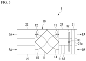
- FIG. 5 is a schematic diagram showing a carbon dioxide recovery device 1 according to Embodiment 3.
- the carbon dioxide recovery device 1 includes an adsorbent, a total heat exchanger 10, a first inflow duct 21, a first outflow duct 22, a second inflow duct 23, and a second outflow duct 24, a dehumidifying material 31, a heat exchanger 32, a switching unit 33.
- the adsorption area A1 is provided in the first inflow duct 21.
- the dehumidifying material 31 is formed in a disk shape with a rotation axis 31a as a center.
- the dehumidifying material 31 is rotatable about the rotation axis 31a.
- the dehumidifying material 31 is provided to be located across the first inflow duct 21 and the second outflow duct 24. In the first inflow duct 21, the dehumidifying material 31 is disposed on an upstream side in the air flow direction with respect to the adsorption area A1.
- the dehumidifying material 31 absorbs moisture in the air flowing through the first inflow duct 21.
- the portion of the dehumidifying material 31 that is disposed in the first inflow duct 21 and has absorbed the moisture can be moved to the second outflow duct 24, and the portion can be dried by the air flowing through the second outflow duct 24.
- the heat exchanger 32 performs heat exchange between the air flowing between the adsorption area A1 and the dehumidifying material 31 in the first inflow duct 21 and the air flowing through the second outflow duct 24.
- the heat exchanger 32 is disposed between the adsorption area A1 and the dehumidifying material 31.
- the switching unit 33 switches between a state in which heat is transferred from the first inflow duct 21 to the second outflow duct 24 by the heat exchanger 32, a state in which heat is transferred from the second outflow duct 24 to the first inflow duct 21 by the heat exchanger 32, and a state in which heat is not transferred between the first inflow duct 21 and the second outflow duct 24.
- the carbon dioxide recovery method according to the present embodiment includes an adsorbing step and a separation step.
- the adsorbing step will be described with reference to FIG. 6A .
- the adsorbent in the adsorption area A1, the adsorbent is brought into contact with air containing carbon dioxide to adsorb carbon dioxide onto the adsorbent.
- the moisture in the air flowing through the first inflow duct 21 is absorbed by the dehumidifying material 31, and thus the dehumidified air flows through the adsorption area A1.
- humidity of the air in contact with the adsorbent is high, there is a possibility that an adsorption efficiency of carbon dioxide by the adsorbent is deteriorated.
- the moisture in the air flowing through the first inflow duct 21 is absorbed by the dehumidifying material 31, so that deterioration in the adsorption efficiency can be prevented.
- the switching unit 33 switches the state to the state in which heat is transferred from the first inflow duct 21 to the second outflow duct 24 by the heat exchanger 32. As a result, as shown by a dotted arrow in FIG. 6A , the heat generated by the dehumidifying material 31 is transferred (released) to the second outflow duct 24.
- a separation step of separating carbon dioxide from the adsorbent which has adsorbed carbon dioxide is performed in the first inflow duct 21. That is, both the adsorption area A1 and the separation area A2 are provided in the first inflow duct 21.
- the adsorbing step will be described with reference to FIG. 6B .
- the separation step in the separation area A2, the carbon dioxide is separated from the adsorbent which has adsorbed the carbon dioxide in the adsorbing step by heating the adsorbent which has adsorbed the carbon dioxide.
- the switching unit 33 switches the state to the state in which heat is not transferred between the first inflow duct 21 and the second outflow duct 24.
- the heat generated by the dehumidifying material 31 is not transferred to the second outflow duct 24 but transported to the separation area A2. Therefore, the heat generated by the dehumidifying material 31 can be used in the separation step.
- the adsorption area A1 is provided in the first inflow duct 21.
- the carbon dioxide recovery device 1 includes a dehumidifying material 31 that is provided on an upstream side with respect to the adsorption area A1 in a flow direction in which air flows through the first inflow duct 21.
- the moisture in the air flowing through the first inflow duct 21 is absorbed by the dehumidifying material 31, and thus dehumidified air flows through the adsorption area A1. Therefore, the adsorption efficiency of carbon dioxide in the adsorption area A1 can be improved.
- the carbon dioxide recovery device 1 includes a heat exchanger 32 that exchanges heat between the air flowing between the adsorption area A1 and the dehumidifying material 31 in the first inflow duct 21 and the air flowing through the second outflow duct 24, a switching unit 33 that switches between a state in which the heat is transferred from the first inflow duct 21 to the second outflow duct 24 by the heat exchanger 32, a state in which the heat is transferred from the second outflow duct 24 to the first inflow duct 21 by the heat exchanger 32, and a state in which the heat is not transferred between the first inflow duct 21 and the second outflow duct 24.
- the switching unit 33 switches the state to the state in which the heat is transferred from the first inflow duct 21 to the second outflow duct 24 by the heat exchanger 32.
- the heat generated in a case where the moisture in the air is absorbed by the dehumidifying material 31 can be transferred (released) to the second outflow duct 24. Therefore, it is possible to prevent the adsorption efficiency of carbon dioxide from being deteriorated due to the heat generated by the dehumidifying material 31.
- the carbon dioxide can also be separated from the adsorbent which has adsorbed the carbon dioxide in the first inflow duct 21 by using the heat generated by the dehumidifying material 31.
- FIG. 7 is a schematic diagram showing a carbon dioxide recovery device 1 according to a modification example of Embodiment 3.
- the separation step of separating the carbon dioxide from the adsorbent is performed at two locations of the first inflow duct 21 and the second outflow duct 24. That is, the separation area A2 is provided in the first inflow duct 21 and the second outflow duct 24.
- the switching unit 33 switches a part of the heat generated by the dehumidifying material 31 to be transferred from the first inflow duct 21 to the second outflow duct 24 by the heat exchanger 32.
- a part of the heat generated by the dehumidifying material 31 is transferred to the separation area A2 of the second outflow duct 24 and is used in the separation step in the separation area A2 of the second outflow duct 24.
- another part of the heat generated by the dehumidifying material 31 is transported to the separation area A2 of the first inflow duct 21 and is used in the separation step in the separation area A2 of the first inflow duct 21.
- the separation step can be performed at two locations, the recovery efficiency of carbon dioxide can be further improved.
- FIG. 8 is a schematic diagram showing a carbon dioxide recovery device 1 according to Embodiment 4.
- the adsorbing step is performed in both the first inflow duct 21 and the second inflow duct 23. That is, the adsorption area A1 is provided in the first inflow duct 21 and the second inflow duct 23.
- the carbon dioxide can be recovered from both the air flowing through the first inflow duct 21 and the air flowing through the second inflow duct 23, the amount of the recovered carbon dioxide is increased, and the recovery efficiency of the carbon dioxide can be further improved.
- the second outflow duct 24 may be provided with a separation area A2 for separating carbon dioxide from the adsorbent which has adsorbed carbon dioxide.
- the adsorbent which has adsorbed the carbon dioxide in the adsorption area A1 of the first inflow duct 21 or the second inflow duct 23 is transported to the separation area A2 of the second outflow duct 24.
- carbon dioxide is separated by heating the adsorbent which has adsorbed the carbon dioxide.
- FIG. 9 is a schematic diagram showing a carbon dioxide recovery device 1 according to Embodiment 5.
- the adsorbing step is performed in the second inflow duct 23, and the separation step is performed in the first inflow duct 21. That is, the adsorption area A1 is provided in the second inflow duct 23, and the separation area A2 is provided in the first inflow duct 21.
- the switching unit 33 switches the state to the state in which heat is transferred from the second outflow duct 24 to the first inflow duct 21 by the heat exchanger 32.
- the adsorption heat in the adsorption area A1 of the second inflow duct 23 is transported to the second outflow duct 24 through the exhaust flow passage 15.
- the adsorption heat transported to the second outflow duct 24 is transferred to the first inflow duct 21 by the heat exchanger 32. Therefore, the adsorption heat in the adsorption area A1 of the second inflow duct 23 can be used in the separation step in the separation area A2 of the first inflow duct 21.
- FIG. 10 is a schematic diagram showing a carbon dioxide recovery device 2 according to Embodiment 6.
- a carbon dioxide recovery device 2 includes an adsorbent, an exhaust ventilation fan 41, an inflow duct 42, and an outflow duct 43. Since the configuration of the adsorbent is the same as that of Embodiment 1, the description thereof will be omitted here.
- the exhaust ventilation fan 41 is provided in an exhaust flow passage 44 for discharging air from the indoor space to the outdoor space.
- the exhaust ventilation fan 41 forms a flow of air from the indoor space to the outdoor space.
- the exhaust ventilation fan 41 is an example of a blower.
- the exhaust flow passage 44 is an example of an air flow passage.
- the inflow duct 42 allows air to flow into the exhaust flow passage 44.
- the inflow duct 42 is disposed on an indoor side of the exhaust flow passage 44.
- the outflow duct 43 allows the air to flow out from the exhaust flow passage 44.
- the outflow duct 43 is disposed on an outdoor side of the exhaust flow passage 44.
- Return air (RA) of the indoor space flows into the exhaust flow passage 44 via the inflow duct 42 by driving of the exhaust ventilation fan 41.
- the return air passes through the exhaust flow passage 44 and is discharged to the outdoor space from the outflow duct 43 as exhaust air (EA).
- EA exhaust air
- the inflow duct 42 is provided with an adsorption area A1 in which carbon dioxide contained in the air is adsorbed by the adsorbent. That is, the adsorbent is disposed in the adsorption area A1.
- the adsorbent is disposed in the adsorption area A1 by fixing a container having air permeability to an inner wall of the inflow duct 42 and accommodating the adsorbent in the container.
- the adsorbent may flow into the adsorption area A1 from an adsorbent transport duct (not shown) intersecting the inflow duct 42.
- the carbon dioxide recovery method according to the present embodiment includes an adsorbing step.
- the adsorbent in the adsorption area A1, the adsorbent is brought into contact with air containing carbon dioxide to adsorb carbon dioxide onto the adsorbent.
- the exhaust ventilation fan 41 forms a flow of the air from the indoor space toward the outdoor space in the exhaust flow passage 44, and the air flows through the adsorption area A1 (that is, the inflow duct 42).
- the carbon dioxide is recovered from the air flowing through the adsorption area A1.
- the carbon dioxide recovery device 2 includes the exhaust ventilation fan 41 that is provided in the exhaust flow passage 44 and that forms a flow of air in the exhaust flow passage 44, the inflow duct 42 through which air flows into the exhaust flow passage 44, the outflow duct 43 through which air flows out from the exhaust flow passage 44, and the adsorbent that adsorbs carbon dioxide in the air.
- the adsorption area A1 in which the carbon dioxide contained in the air is adsorbed by the adsorbent is provided in the inflow duct 42.
- the carbon dioxide recovery method includes an adsorbing step of bringing the air into contact with the adsorbent that adsorbs carbon dioxide in the adsorption area A1 provided in the inflow duct 42 through which the air flows into the exhaust flow passage 44, to adsorb the carbon dioxide onto the adsorbent.
- the exhaust ventilation fan 41 that is provided in the exhaust flow passage 44 forms a flow of air in the exhaust flow passage 44 to cause the air to flow the adsorption area A1.
- the exhaust ventilation fan 41 is used to cause the air to flow the adsorption area A1 provided in the inflow duct 42, and cause the adsorbent to adsorb the carbon dioxide contained in the air. Since carbon dioxide can be directly recovered from the air that flows through the inflow duct 42, the recovery efficiency of carbon dioxide can be improved.
- the outflow duct 43 may be provided with a separation area A2 for separating carbon dioxide from the adsorbent which has adsorbed carbon dioxide.
- the adsorbent which has adsorbed the carbon dioxide in the adsorption area A1 of the inflow duct 42 is transported to the separation area A2 of the outflow duct 43.
- carbon dioxide is separated by heating the adsorbent which has adsorbed the carbon dioxide.
- a separation step of separating carbon dioxide from the adsorbent which has adsorbed carbon dioxide is performed. That is, both the adsorption area A1 and the separation area A2 are provided in the inflow duct 42.
- FIG. 11 is a schematic diagram showing a carbon dioxide recovery device 2 according to a modification example of Embodiment 6.
- the adsorption area A1 is provided in the outflow duct 43.
- the adsorbent In the adsorbing step, in the adsorption area A1, the adsorbent is brought into contact with air containing carbon dioxide to adsorb carbon dioxide onto the adsorbent. At this time, the exhaust ventilation fan 41 forms a flow of the air from the outdoor space toward the indoor space in the exhaust flow passage 44, and the air flows through the adsorption area A1 (that is, the outflow duct 43).
- the carbon dioxide recovery device 2 includes the exhaust ventilation fan 41 that is provided in the exhaust flow passage 44 and that forms a flow of air in the exhaust flow passage 44, the inflow duct 42 through which air flows into the exhaust flow passage 44, the outflow duct 43 through which air flows out from the exhaust flow passage 44, and the adsorbent that adsorbs carbon dioxide in the air.
- the adsorption area A1 in which the carbon dioxide contained in the air is adsorbed by the adsorbent is provided in the outflow duct 43.
- the carbon dioxide recovery method includes an adsorbing step of bringing the air into contact with the adsorbent that adsorbs carbon dioxide in the adsorption area A1 provided in the outflow duct 43 through which the air flows into the exhaust flow passage 44, to adsorb the carbon dioxide onto the adsorbent.
- the exhaust ventilation fan 41 that is provided in the exhaust flow passage 44 forms a flow of air in the exhaust flow passage 44 to cause the air to flow the adsorption area A1.
- the exhaust ventilation fan 41 is used to cause the air to flow the adsorption area A1 provided in the outflow duct 43, and cause the adsorbent to adsorb the carbon dioxide contained in the air. Since carbon dioxide can be directly recovered from the air that flows through the outflow duct 43, the recovery efficiency of carbon dioxide can be improved.
- the inflow duct 42 may be provided with a separation area A2 for separating carbon dioxide from the adsorbent which has adsorbed carbon dioxide.
- the adsorbent which has adsorbed the carbon dioxide in the adsorption area A1 of the outflow duct 43 is transported to the separation area A2 of the inflow duct 42.
- carbon dioxide is separated by heating the adsorbent which has adsorbed the carbon dioxide.
- a separation step of separating carbon dioxide from the adsorbent which has adsorbed carbon dioxide may be performed. That is, both the adsorption area A1 and the separation area A2 are provided in the outflow duct 43.
- FIG. 12 is a block diagram showing a carbon dioxide recovery system 3 according to Embodiment 7.
- the carbon dioxide recovery system 3 includes a first carbon dioxide recovery device 1A, a second carbon dioxide recovery device 1B, a third carbon dioxide recovery device 1C, a first separation device 50A, a second separation device 50B, a third separation device 50C, and a methanation system 60.
- the carbon dioxide recovery devices 1A, 1B, and 1C and the separation devices 50A, 50B, and 50C are installed in a common building.
- the first carbon dioxide recovery device 1A and the first separation device 50A are installed on the first floor
- the second carbon dioxide recovery device 1B and the second separation device 50B are installed on the second floor
- the third carbon dioxide recovery device 1C and the third separation device 50C are installed on the third floor.
- the third carbon dioxide recovery device 1C and the third separation device 50C may be installed on the first floor
- the first carbon dioxide recovery device 1A and the first separation device 50A may be installed on the third floor.
- the configurations of the carbon dioxide recovery devices 1A, 1B, and 1C are the same as the configuration of the carbon dioxide recovery device 1 according to Embodiment 1. That is, the carbon dioxide recovery devices 1A, 1B, and 1C each include the adsorbent, the total heat exchanger 10, the first inflow duct 21, the first outflow duct 22, the second inflow duct 23, and the second outflow duct 24.
- the adsorption area A1 in which the carbon dioxide contained in the air is adsorbed by the adsorbent is provided in the second inflow duct 23.
- the adsorption area A1 may be provided in the first inflow duct 21.
- the separation devices 50A, 50B, and 50C have a function of separating carbon dioxide from the adsorbent.
- the separation devices 50A, 50B, and 50C may include a heater and may separate carbon dioxide by heating the adsorbent.
- the separation devices 50A, 50B, and 50C may include a vacuum pump, and separate carbon dioxide by placing the adsorbent under a reduced pressure condition.
- the adsorbent which has absorbed carbon dioxide is transported from the first carbon dioxide recovery device 1A.
- the carbon dioxide separated from the adsorbent in the first separation device 50A is transported to the second carbon dioxide recovery device 1B.
- the adsorbent which has adsorbed the carbon dioxide is transported from the second carbon dioxide recovery device 1B.
- the carbon dioxide separated from the adsorbent in the second separation device 50B is transported to the third carbon dioxide recovery device 1C.
- the adsorbent which has adsorbed the carbon dioxide is transported from the third carbon dioxide recovery device 1C.
- the carbon dioxide separated from the adsorbent in the third separation device 50C is transported to the methanation system 60.
- the methanation system 60 has a function of generating methane using carbon dioxide, hydrogen, water, electric power, and the like.
- the methanation system 60 is installed on a roof of a building.
- the carbon dioxide recovery method includes an adsorbing step, an adsorbent transporting step, a separation step, and a carbon dioxide transporting step.
- the adsorbent is brought into contact with air in the adsorption area A1 of the first carbon dioxide recovery device 1A to adsorb carbon dioxide onto the adsorbent.
- the adsorbent which has adsorbed the carbon dioxide is transported from the adsorption area A1 of the first carbon dioxide recovery device 1A to the first separation device 50A.
- the first separation device 50A separates carbon dioxide from the adsorbent which has adsorbed the carbon dioxide.
- the separated carbon dioxide is transported to the second carbon dioxide recovery device 1B.
- the adsorbing step, the adsorbent transporting step, the separation step, and the carbon dioxide transporting step are also performed.
- the adsorbent is brought into contact with air in the adsorption area A1 of the second carbon dioxide recovery device 1B to adsorb carbon dioxide onto the adsorbent.
- the air flowing through the second carbon dioxide recovery device 1B is mixed with the carbon dioxide transported from the first separation device 50A, a carbon dioxide concentration is increased as compared with the air flowing through the first carbon dioxide recovery device 1A.
- adsorbent which has adsorbed the carbon dioxide is transported from the adsorption area A1 of the second carbon dioxide recovery device 1B to the second separation device 50B.
- the second separation device 50B separates carbon dioxide from the adsorbent which has adsorbed the carbon dioxide.
- the separated carbon dioxide is transported to the third carbon dioxide recovery device 1C.
- the adsorbing step, the adsorbent transporting step, the separation step, and the carbon dioxide transporting step are also performed.
- adsorbent in a third adsorbing step, the adsorbent is brought into contact with air in the adsorption area A1 of the third carbon dioxide recovery device 1C to adsorb carbon dioxide onto the adsorbent.
- air flowing through the third carbon dioxide recovery device 1C is mixed with the carbon dioxide transported from the second separation device 50B, a carbon dioxide concentration is further increased.
- adsorbent which has adsorbed the carbon dioxide is transported from the adsorption area A1 of the third carbon dioxide recovery device 1C to the third separation device 50C.
- the third separation device 50C separates carbon dioxide from the adsorbent which has adsorbed the carbon dioxide.
- a third carbon dioxide transporting step the separated carbon dioxide is transported to the methanation system 60.
- carbon dioxide is recovered.
- the carbon dioxide concentration of the air to be adsorbed can be increased, so that the recovery efficiency of carbon dioxide is improved.
- a step of concentrating carbon dioxide is not necessary. Further, the recovered carbon dioxide can be easily transported to the methanation system 60.
- the carbon dioxide recovery method includes the separation step of separating carbon dioxide from the adsorbent which has adsorbed the carbon dioxide in the adsorbing step, the carbon dioxide transporting step of transporting the carbon dioxide separated in the separation step to a second carbon dioxide recovery device 1B, and the second adsorbing step of bringing the adsorbent that adsorbs carbon dioxide into contact with air in the second carbon dioxide recovery device 1B to adsorb the carbon dioxide onto the adsorbent.
- the carbon dioxide separated in the separation step is mixed, and the carbon dioxide contained in the air in which the carbon dioxide concentration is increased is adsorbed onto the adsorbent, so that the recovery efficiency of the carbon dioxide can be further improved.
- FIG. 13 is a perspective view showing a carbon dioxide recovery system 4 according to Embodiment 8.
- the carbon dioxide recovery system 4 includes a first carbon dioxide recovery device 1A, a second carbon dioxide recovery device 1B, and a transport duct 70.
- the second carbon dioxide recovery device 1B is disposed below the first carbon dioxide recovery device 1A.
- the basic configurations of the carbon dioxide recovery devices 1A and 1B are the same as the carbon dioxide recovery device 1 according to Embodiment 1. That is, the carbon dioxide recovery devices 1A and 1B each include the total heat exchanger 10, the first inflow duct 21, the first outflow duct 22, the second inflow duct 23, and the second outflow duct 24. In the present embodiment, a common adsorbent is used in the carbon dioxide recovery devices 1A and 1B. The adsorption area A1 in which the carbon dioxide contained in the air is adsorbed onto the adsorbent is provided in the second inflow duct 23 of the first carbon dioxide recovery device 1A.
- the adsorbent which has adsorbed the carbon dioxide in the adsorption area A1 of the first carbon dioxide recovery device 1A is transported to the second outflow duct 24 of the second carbon dioxide recovery device 1B.
- a separation area A2 in which carbon dioxide is separated from the adsorbent which has adsorbed the carbon dioxide is provided in the second outflow duct 24 of the second carbon dioxide recovery device 1B.
- the transport duct 70 connects the second inflow duct 23 of the first carbon dioxide recovery device 1A and the second outflow duct 24 of the second carbon dioxide recovery device 1B to each other.
- the transport duct 70 is provided to intersect each of the second inflow duct 23 of the first carbon dioxide recovery device 1A and the second outflow duct 24 of the second carbon dioxide recovery device 1B.
- the adsorbent flows into the transport duct 70.
- the adsorbent which has adsorbed the carbon dioxide in the second inflow duct 23 of the first carbon dioxide recovery device 1A is transported to the second outflow duct 24 of the second carbon dioxide recovery device 1B by using the transport duct 70.
- the carbon dioxide recovery method includes an adsorbing step, an adsorbent transporting step, and a separation step.
- the adsorbent flows into the transport duct 70, and the adsorbent is brought into contact with the air in the adsorption area A1 provided in the second inflow duct 23 of the first carbon dioxide recovery device 1A to adsorb carbon dioxide onto the adsorbent.
- the adsorbent which has adsorbed the carbon dioxide in the adsorbing step is transported from the second inflow duct 23 of the first carbon dioxide recovery device 1A to the second outflow duct 24 of the second carbon dioxide recovery device 1B by the transport duct 70.
- the carbon dioxide is separated from the adsorbent which has adsorbed the carbon dioxide, in the separation area A2 provided in the second outflow duct 24 of the second carbon dioxide recovery device 1B.
- the separation area A2 may be provided in the second inflow duct 23.
- a gas cylinder capable of storing carbon dioxide may be provided instead of the methanation system 60 described in Embodiment 7, or in addition to the methanation system 60.
- the carbon dioxide separated from the adsorbent by the separation devices 50A, 50B, and 50C can be stored in the gas cylinder.
- the gas cylinder in which the carbon dioxide is stored may be transported to another place (for example, a factory or the like), and the carbon dioxide may be used.
- the carbon dioxide recovery devices 2 according to Embodiment 5 or 6 may be used as the carbon dioxide recovery devices 1A, 1B, and 1C.
Landscapes
- Chemical & Material Sciences (AREA)
- Engineering & Computer Science (AREA)
- Analytical Chemistry (AREA)
- General Chemical & Material Sciences (AREA)
- Oil, Petroleum & Natural Gas (AREA)
- Chemical Kinetics & Catalysis (AREA)
- Combustion & Propulsion (AREA)
- Mechanical Engineering (AREA)
- General Engineering & Computer Science (AREA)
- Separation Of Gases By Adsorption (AREA)
- Treating Waste Gases (AREA)
Abstract
Description
- The present invention relates to a carbon dioxide recovery device and a carbon dioxide recovery method.
-
Patent Document 1 discloses a device that removes carbon dioxide in air using an adsorbent capable of adsorbing carbon dioxide. - Patent Document 1: Japanese Unexamined Patent Application Publication
JP 2020- 89 891 A - It is required to improve the recovery efficiency of carbon dioxide by the adsorbent.
- In view of the above circumstances, the present invention is to provide a carbon dioxide recovery device and a carbon dioxide recovery method capable of improving a recovery efficiency of carbon dioxide.
- One aspect of the carbon dioxide recovery device according to the present invention includes a blower that is provided in an air flow passage through which air flows between an indoor space and an outdoor space and that forms a flow of air in the air flow passage; an inflow duct through which air flows into the air flow passage; an outflow duct through which air flows out from the air flow passage; and an adsorbent that adsorbs carbon dioxide in air, in which at least one of the inflow duct and the outflow duct is provided with an adsorption area in which the carbon dioxide contained in air is adsorbed by the adsorbent.
- One aspect of a carbon dioxide recovery method according to the present invention is a carbon dioxide recovery method of recovering carbon dioxide by using a carbon dioxide recovery device that includes a blower that is provided in an air flow passage through which air flows between an indoor space and an outdoor space and that forms a flow of air in the air flow passage, an inflow duct through which air flows into the air flow passage, an outflow duct through which air flows out from the air flow passage, and an adsorbent that adsorbs carbon dioxide in air, the carbon dioxide recovery method includes an adsorbing step of bringing the adsorbent into contact with air in an adsorption area provided in at least one of the inflow duct and the outflow duct to adsorb the carbon dioxide onto the adsorbent, in which in the adsorbing step, the blower forms a flow of air in the air flow passage by the blower to cause air to flow in the adsorption area.
- Another aspect of the carbon dioxide recovery method according to the present invention is a carbon dioxide recovery method of recovering carbon dioxide by using a carbon dioxide recovery device that includes a total heat exchanger in which an air supply flow passage and an exhaust flow passage are formed and that has a suction blower provided in the air supply flow passage and an exhaust blower provided in the exhaust flow passage, a first inflow duct through which air flows into the air supply flow passage, a first outflow duct through which air flows out from the air supply flow passage, a second inflow duct through which air flows into the exhaust flow passage, a second outflow duct through which air flows out from the exhaust flow passage, and an adsorbent that adsorbs carbon dioxide in air, the carbon dioxide recovery method includes an adsorbing step of bringing the adsorbent into contact with air in an adsorption area provided in at least one of the first inflow duct and the second inflow duct to adsorb the carbon dioxide onto the adsorbent, in which in the adsorbing step, the blower forms a flow of air in the air flow passage or the exhaust flow passage by the suction blower or the exhaust blower to cause air to flow in the adsorption area.
- According to the present invention, it is possible to provide a carbon dioxide recovery device and a carbon dioxide recovery method capable of improving a recovery efficiency of carbon dioxide.
-
-
FIG. 1 is a schematic diagram showing a carbon dioxide recovery device according toEmbodiment 1. -
FIG. 2 is a schematic diagram showing a carbon dioxide recovery device according to a modification example ofEmbodiment 1. -
FIG. 3 is a schematic diagram showing a carbon dioxide recovery device according toEmbodiment 2. -
FIG. 4 is a schematic diagram showing a carbon dioxide recovery device according to a modification example ofEmbodiment 2. -
FIG. 5 is a schematic diagram showing a carbon dioxide recovery device according toEmbodiment 3. -
FIG. 6A is a diagram showing an adsorbing step in the carbon dioxide recovery device according toEmbodiment 3. -
FIG. 6B is a diagram showing a separation step in the carbon dioxide recovery device according toEmbodiment 3. -
FIG. 7 is a diagram showing a separation step in a carbon dioxide recovery device according to a modification example ofEmbodiment 3. -
FIG. 8 is a schematic diagram showing a carbon dioxide recovery device according to Embodiment 4. -
FIG. 9 is a schematic diagram showing a carbon dioxide recovery device according to Embodiment 5. -
FIG. 10 is a schematic diagram showing a carbon dioxide recovery device according to Embodiment 6. -
FIG. 11 is a schematic diagram showing a carbon dioxide recovery device according to a modification example of Embodiment 6. -
FIG. 12 is a block diagram showing a carbon dioxide recovery system according to Embodiment 7. -
FIG. 13 is a perspective view showing a carbon dioxide recovery system according to Embodiment 8. - Hereinafter, an embodiment of the present invention will be described with reference to the drawings. The scope of the present invention is not limited to the following embodiment, and can be changed in any way within the scope of the technical ideas of the present invention.
-
FIG. 1 is a schematic diagram showing a carbondioxide recovery device 1 according toEmbodiment 1. - As shown in
FIG. 1 , the carbondioxide recovery device 1 includes an adsorbent, a stationary total heat exchanger 10 (hereinafter, also simply referred to as a "total heat exchanger 10"), afirst inflow duct 21, afirst outflow duct 22, asecond inflow duct 23, and asecond outflow duct 24. - The
total heat exchanger 10 includes a totalheat exchange element 11, asuction blower 12, and anexhaust blower 13. In addition, in thetotal heat exchanger 10, an airsupply flow passage 14 for supplying air from the outdoor space to the indoor space and anexhaust flow passage 15 for discharging air from the indoor space to the outdoor space are formed. The airsupply flow passage 14 and theexhaust flow passage 15 are examples of an air flow passage. - A part of the air
supply flow passage 14 and a part of theexhaust flow passage 15 are formed in the totalheat exchange element 11. The totalheat exchange element 11 performs heat exchange between air that flows through the airsupply flow passage 14 and air that flows through theexhaust flow passage 15. - The
suction blower 12 is installed in the airsupply flow passage 14. Thesuction blower 12 forms a flow of air from the outdoor space to the indoor space. - The
exhaust blower 13 is installed in theexhaust flow passage 15. Theexhaust blower 13 forms a flow of air from the indoor space to the outdoor space. - The
suction blower 12 and theexhaust blower 13 are examples of a blower. - The
first inflow duct 21 allows air to flow into the airsupply flow passage 14. - The
first outflow duct 22 allows the air to flow out from the airsupply flow passage 14. - The
second inflow duct 23 allows air to flow into theexhaust flow passage 15. - The
second outflow duct 24 allows the air to flow out from theexhaust flow passage 15. - The
first inflow duct 21, thefirst outflow duct 22, thesecond inflow duct 23, and thesecond outflow duct 24 are provided in the building, and are disposed, for example, in a ceiling space. - Outdoor air (OA) flows into the air
supply flow passage 14 via thefirst inflow duct 21 by the driving of thesuction blower 12. The outdoor air passes through the airsupply flow passage 14 and is supplied indoor space from thefirst outflow duct 22 as supply air (SA). - Return air (RA) of the indoor space flows into the
exhaust flow passage 15 via thesecond inflow duct 23 by driving of theexhaust blower 13. The return air passes through theexhaust flow passage 15 and is discharged to the outdoor space from thesecond outflow duct 24 as exhaust air (EA). - As a result, the indoor ventilation is performed. In this case, in the total
heat exchange element 11, heat exchange is performed between the air that flows through the airsupply flow passage 14 and the air that flows through theexhaust flow passage 15. - The adsorbent includes a material capable of adsorbing carbon dioxide. Examples of a material capable of adsorbing carbon dioxide include amine, zeolite, silica gel, diatomaceous earth, alumina, activated carbon, and the like. A plurality of materials may be selected and adopted from the above, or a material other than the above may be adopted. The adsorbent may have a granular shape (for example, bead shape (spherical) or pellet shape (cylindrical)). Alternatively, a powdery adsorbent may be adopted. In this case, the powdery adsorbent may be carried on a surface of a base material. The base material may have, for example, a honeycomb shape.
- In the present embodiment, the
second inflow duct 23 is provided with an adsorption area A1 in which the carbon dioxide contained in the air is adsorbed by the adsorbent. The adsorbent is disposed in the adsorption area A1. For example, the adsorbent is disposed in the adsorption area A1 by fixing a container having air permeability to an inner wall of thesecond inflow duct 23 and accommodating the adsorbent in the container. Alternatively, the adsorbent may flow into the adsorption area A1 from an adsorbent transport duct (not shown) intersecting thesecond inflow duct 23. - The carbon dioxide recovery method according to the present embodiment includes an adsorbing step.
- In the adsorbing step, in the adsorption area A1, the adsorbent is brought into contact with air containing carbon dioxide to adsorb carbon dioxide onto the adsorbent. At this time, the
exhaust blower 13 forms a flow of the air from the indoor space toward the outdoor space in theexhaust flow passage 15, and the air flows through the adsorption area A1 (that is, the second inflow duct 23). As a result, the carbon dioxide is recovered from the air flowing through the adsorption area A1. - As described above, the carbon
dioxide recovery device 1 according to the present embodiment includes theexhaust blower 13 that is provided in theexhaust flow passage 15 and that forms a flow of air in theexhaust flow passage 15, thesecond inflow duct 23 through which air flows into theexhaust flow passage 15, thesecond outflow duct 24 through which air flows out from theexhaust flow passage 15, and the adsorbent that adsorbs carbon dioxide in the air. An adsorption area A1 in which the carbon dioxide contained in the air is adsorbed by the adsorbent is provided in thesecond inflow duct 23. - In addition, the carbon dioxide recovery method according to the present embodiment includes an adsorbing step of bringing the air into contact with the adsorbent that adsorbs carbon dioxide in the adsorption area A1 provided in the
second inflow duct 23 through which the air flows into theexhaust flow passage 15, to adsorb the carbon dioxide onto the adsorbent. In the adsorbing step, theexhaust blower 13 that is provided in theexhaust flow passage 15 forms a flow of air in theexhaust flow passage 15 to cause the air to flow the adsorption area A1. - The
exhaust blower 13 is used to cause the air to flow into the adsorption area A1 provided in thesecond inflow duct 23, and cause the adsorbent to adsorb the carbon dioxide contained in the air. Since carbon dioxide can be directly recovered from the air that flows through thesecond inflow duct 23, the recovery efficiency of carbon dioxide can be improved. In addition, since a dedicated blower or the like for generating an air flow is not required, it is possible to save energy and reduce costs as compared with a case of using a dedicated blower or the like, and it is possible to improve the recovery efficiency of carbon dioxide in the entire device. - In addition, the adsorption area A1 is provided in the
second inflow duct 23. - A carbon dioxide concentration of indoor air is often increased with human respiration. The indoor air having such a high carbon dioxide concentration flows into the
second inflow duct 23. By providing the adsorption area A1 in thesecond inflow duct 23, it is possible to recover the carbon dioxide from the air having the high carbon dioxide concentration, and it is possible to further increase the recovery efficiency of the carbon dioxide. Further, since the air flowing into thesecond inflow duct 23 is not affected by the fluctuation of humidity of outside air and the humidity is stable, the carbon dioxide can be stably recovered without the adsorption performance of the carbon dioxide by the adsorbent being deteriorated. -
FIG. 2 is a schematic diagram showing a carbondioxide recovery device 1 according to a modification example ofEmbodiment 1. - In the present modification example, the adsorption area A1 is provided in the
first inflow duct 21. - In the adsorbing step, in the adsorption area A1, the adsorbent is brought into contact with air containing carbon dioxide to adsorb carbon dioxide onto the adsorbent. At this time, the
suction blower 12 forms a flow of the air from the outdoor space toward the indoor space in the airsupply flow passage 14, and the air flows through the adsorption area A1 (that is, the first inflow duct 21). - The carbon
dioxide recovery device 1 according to the present modification example includes thesuction blower 12 that is provided in the airsupply flow passage 14 and that forms a flow of air in the airsupply flow passage 14, thefirst inflow duct 21 through which air flows into the airsupply flow passage 14, thefirst outflow duct 22 through which air flows out from the airsupply flow passage 14, and the adsorbent that adsorbs carbon dioxide in the air. The adsorption area A1 in which the carbon dioxide contained in the air is adsorbed by the adsorbent is provided in thefirst inflow duct 21. - In addition, the carbon dioxide recovery method according to the present modification example includes an adsorbing step of bringing the air into contact with the adsorbent that adsorbs carbon dioxide in the adsorption area A1 provided in the
first inflow duct 21 through which the air flows into the airsupply flow passage 14, to adsorb the carbon dioxide onto the adsorbent. In the adsorbing step, thesuction blower 12 that is provided in the airsupply flow passage 14 forms a flow of air in the airsupply flow passage 14 to cause the air to flow the adsorption area A1. - The
suction blower 12 is used to cause the air to flow the adsorption area A1 provided in thefirst inflow duct 21, and cause the adsorbent to adsorb the carbon dioxide contained in the air. Since carbon dioxide can be directly recovered from the air that flows through thefirst inflow duct 21, the recovery efficiency of carbon dioxide can be improved. - Next, a carbon
dioxide recovery device 1 and a carbon dioxide recovery method according toEmbodiment 2 will be described. Since the basic configuration of the carbondioxide recovery device 1 according to the present embodiment is the same as that ofEmbodiment 1, the carbondioxide recovery device 1 will be described with reference to the differences. -
FIG. 3 is a schematic diagram showing a carbondioxide recovery device 1 according toEmbodiment 2. - As shown in
FIG. 3 , in the present embodiment, a separation area A2 in which carbon dioxide is separated from an adsorbent that adsorbs carbon dioxide is provided in thesecond outflow duct 24. - The adsorbent which has adsorbed the carbon dioxide in the adsorption area A1 of the
second inflow duct 23 is transported to the separation area A2 of thesecond outflow duct 24. For example, the adsorbent may be transported from the adsorption area A1 to the separation area A2 by using a transport duct (not shown) that connects thesecond inflow duct 23 and thesecond outflow duct 24. - The separation area A2 is disposed with the adsorbent transported from the adsorption area A1. For example, the adsorbent which has adsorbed the carbon dioxide is disposed in the separation area A2 by fixing a container having air permeability to an inner wall of the
second outflow duct 24 and accommodating the adsorbent in the container. Alternatively, the adsorbent may flow into the separation area A2 from the adsorbent transport duct (not shown) intersecting thesecond outflow duct 24. - In the separation area A2, carbon dioxide is separated by heating the adsorbent which has adsorbed the carbon dioxide. A heating temperature is, for example, 120 °C to 160 °C. The heating temperature may be appropriately changed depending on the specific material of the adsorbent.
- The carbon dioxide recovery method according to the present embodiment includes an adsorbing step and a separation step. Since the adsorbing step is the same as in
Embodiment 1, a description thereof will be omitted here. - In the separation step, in the separation area A2, the carbon dioxide is separated from the adsorbent which has adsorbed the carbon dioxide in the adsorbing step by heating the adsorbent which has adsorbed the carbon dioxide.
- Here, in a case where the adsorbent adsorbs carbon dioxide in the adsorption area A1, adsorption heat is generated. This adsorption heat is transported from the adsorption area A1 of the
second inflow duct 23 to the separation area A2 of thesecond outflow duct 24 through theexhaust flow passage 15. Therefore, the adsorption heat of the adsorbent in a case of adsorbing carbon dioxide can be used in the separation step. - In addition, the total
heat exchange element 11 performs heat exchange between the air flowing through the airsupply flow passage 14 and the air flowing through theexhaust flow passage 15. In a case in which the outdoor temperature is higher than the indoor temperature, the heat contained in the air flowing in from thefirst inflow duct 21 and flowing through the airsupply flow passage 14 is transferred to the air flowing through theexhaust flow passage 15 by the heat exchange by the totalheat exchange element 11. - That is, the heat contained in the air flowing in from the
first inflow duct 21 is transported to the separation area A2 of thesecond outflow duct 24 by the totalheat exchange element 11. Therefore, the heat contained in the air flowing in from thefirst inflow duct 21 can be used in the separation step. - A heater (not shown) may be provided in the
second outflow duct 24 on an upstream side in an air flow direction with respect to the separation area A2. By heating the air flowing through the separation area A2 by the heater, carbon dioxide can be more effectively separated from the adsorbent. Even in this case, by using the adsorption heat and the heat contained in the air flowing in from thefirst inflow duct 21 in the separation step, the heating energy by the heater can be suppressed, and energy saving can be achieved. - In the carbon
dioxide recovery device 1 according to the present embodiment, thesecond outflow duct 24 is provided with a separation area A2 in which carbon dioxide is separated from the adsorbent which has adsorbed the carbon dioxide. - The carbon dioxide recovery method according to the present embodiment further includes a separation step of separating carbon dioxide from the adsorbent which has adsorbed the carbon dioxide in the separation area A2 provided in the
second outflow duct 24. In the separation step, the carbon dioxide is separated from the adsorbent by using the adsorption heat generated when the adsorbent adsorbs the carbon dioxide in the adsorbing step and the heat contained in the air flowing in from thefirst inflow duct 21. - The adsorption heat generated when the adsorbent adsorbs the carbon dioxide in the adsorption area A1 and the heat contained in the air flowing in from the
first inflow duct 21 can be transported to the separation area A2 and used for separating carbon dioxide from the adsorbent. Therefore, for example, it is not necessary to heat air by the heater in order to separate carbon dioxide, or heating energy by the heater can be suppressed, so that energy saving can be achieved, and the recovery efficiency of carbon dioxide in the entire device can be improved. -
FIG. 4 is a schematic diagram showing a carbondioxide recovery device 1 according to a modification example ofEmbodiment 2. - In the present modification example, the adsorption area A1 is provided in the
first inflow duct 21, and the separation area A2 is provided in thesecond outflow duct 24. That is, the adsorbing step is performed in the adsorption area A1 of thefirst inflow duct 21. The adsorbent which has adsorbed the carbon dioxide in the adsorption area A1 of thefirst inflow duct 21 is transported to the separation area A2 of thesecond outflow duct 24. In the separation area A2 of thesecond outflow duct 24, the separation step is performed. - The adsorption heat generated when the adsorbent adsorbs the carbon dioxide in the adsorption area A1 of the
first inflow duct 21 and the heat contained in the air flowing in from thefirst inflow duct 21 are transported to the separation area A2 of thesecond outflow duct 24 by the totalheat exchange element 11. Therefore, the adsorption heat generated when the adsorbent adsorbs carbon dioxide and the heat contained in the air flowing in from thefirst inflow duct 21 can be used in the separation step. - Next, a carbon
dioxide recovery device 1 and a carbon dioxide recovery method according toEmbodiment 3 will be described. Since the basic configuration of the carbondioxide recovery device 1 according to the present embodiment is the same as that ofEmbodiments dioxide recovery device 1 will be described with reference to the differences. -
FIG. 5 is a schematic diagram showing a carbondioxide recovery device 1 according toEmbodiment 3. - As shown in
FIG. 5 , in the present embodiment, the carbondioxide recovery device 1 includes an adsorbent, atotal heat exchanger 10, afirst inflow duct 21, afirst outflow duct 22, asecond inflow duct 23, and asecond outflow duct 24, adehumidifying material 31, aheat exchanger 32, a switchingunit 33. In addition, the adsorption area A1 is provided in thefirst inflow duct 21. - The
dehumidifying material 31 is formed in a disk shape with arotation axis 31a as a center. Thedehumidifying material 31 is rotatable about therotation axis 31a. Thedehumidifying material 31 is provided to be located across thefirst inflow duct 21 and thesecond outflow duct 24. In thefirst inflow duct 21, thedehumidifying material 31 is disposed on an upstream side in the air flow direction with respect to the adsorption area A1. Thedehumidifying material 31 absorbs moisture in the air flowing through thefirst inflow duct 21. - The air in which the moisture is absorbed by the
dehumidifying material 31 flows through the adsorption area A1. By rotating thedehumidifying material 31, the portion of thedehumidifying material 31 that is disposed in thefirst inflow duct 21 and has absorbed the moisture can be moved to thesecond outflow duct 24, and the portion can be dried by the air flowing through thesecond outflow duct 24. - The
heat exchanger 32 performs heat exchange between the air flowing between the adsorption area A1 and thedehumidifying material 31 in thefirst inflow duct 21 and the air flowing through thesecond outflow duct 24. In thefirst inflow duct 21, theheat exchanger 32 is disposed between the adsorption area A1 and thedehumidifying material 31. - The switching
unit 33 switches between a state in which heat is transferred from thefirst inflow duct 21 to thesecond outflow duct 24 by theheat exchanger 32, a state in which heat is transferred from thesecond outflow duct 24 to thefirst inflow duct 21 by theheat exchanger 32, and a state in which heat is not transferred between thefirst inflow duct 21 and thesecond outflow duct 24. - The carbon dioxide recovery method according to the present embodiment includes an adsorbing step and a separation step.
- The adsorbing step will be described with reference to
FIG. 6A . In the adsorbing step, in the adsorption area A1, the adsorbent is brought into contact with air containing carbon dioxide to adsorb carbon dioxide onto the adsorbent. In this case, the moisture in the air flowing through thefirst inflow duct 21 is absorbed by thedehumidifying material 31, and thus the dehumidified air flows through the adsorption area A1. In a case where humidity of the air in contact with the adsorbent is high, there is a possibility that an adsorption efficiency of carbon dioxide by the adsorbent is deteriorated. The moisture in the air flowing through thefirst inflow duct 21 is absorbed by thedehumidifying material 31, so that deterioration in the adsorption efficiency can be prevented. - Here, in a case where the
dehumidifying material 31 absorbs the moisture in the air, heat is generated. The switchingunit 33 switches the state to the state in which heat is transferred from thefirst inflow duct 21 to thesecond outflow duct 24 by theheat exchanger 32. As a result, as shown by a dotted arrow inFIG. 6A , the heat generated by thedehumidifying material 31 is transferred (released) to thesecond outflow duct 24. - In a case where a temperature of the air in contact with the adsorbent is high, there is a possibility that the adsorption efficiency of carbon dioxide by the adsorbent is deteriorated. By releasing the heat generated by the
dehumidifying material 31 to thesecond outflow duct 24, it is possible to prevent the temperature of the air flowing through the adsorption area A1 from rising, and thus it is possible to prevent deterioration in the adsorption efficiency. - In the present embodiment, in the
first inflow duct 21, after the adsorbing step, a separation step of separating carbon dioxide from the adsorbent which has adsorbed carbon dioxide is performed. That is, both the adsorption area A1 and the separation area A2 are provided in thefirst inflow duct 21. - The adsorbing step will be described with reference to
FIG. 6B . In the separation step, in the separation area A2, the carbon dioxide is separated from the adsorbent which has adsorbed the carbon dioxide in the adsorbing step by heating the adsorbent which has adsorbed the carbon dioxide. At this time, the switchingunit 33 switches the state to the state in which heat is not transferred between thefirst inflow duct 21 and thesecond outflow duct 24. As a result, as shown by a dotted arrow inFIG. 6B , the heat generated by thedehumidifying material 31 is not transferred to thesecond outflow duct 24 but transported to the separation area A2. Therefore, the heat generated by thedehumidifying material 31 can be used in the separation step. - In the carbon
dioxide recovery device 1 according to the present embodiment, the adsorption area A1 is provided in thefirst inflow duct 21. The carbondioxide recovery device 1 includes adehumidifying material 31 that is provided on an upstream side with respect to the adsorption area A1 in a flow direction in which air flows through thefirst inflow duct 21. - The moisture in the air flowing through the
first inflow duct 21 is absorbed by thedehumidifying material 31, and thus dehumidified air flows through the adsorption area A1. Therefore, the adsorption efficiency of carbon dioxide in the adsorption area A1 can be improved. - In addition, the carbon
dioxide recovery device 1 includes aheat exchanger 32 that exchanges heat between the air flowing between the adsorption area A1 and thedehumidifying material 31 in thefirst inflow duct 21 and the air flowing through thesecond outflow duct 24, a switchingunit 33 that switches between a state in which the heat is transferred from thefirst inflow duct 21 to thesecond outflow duct 24 by theheat exchanger 32, a state in which the heat is transferred from thesecond outflow duct 24 to thefirst inflow duct 21 by theheat exchanger 32, and a state in which the heat is not transferred between thefirst inflow duct 21 and thesecond outflow duct 24. - In a case where the carbon dioxide is adsorbed in the adsorption area A1, the switching
unit 33 switches the state to the state in which the heat is transferred from thefirst inflow duct 21 to thesecond outflow duct 24 by theheat exchanger 32. As a result, the heat generated in a case where the moisture in the air is absorbed by thedehumidifying material 31 can be transferred (released) to thesecond outflow duct 24. Therefore, it is possible to prevent the adsorption efficiency of carbon dioxide from being deteriorated due to the heat generated by thedehumidifying material 31. - In addition, by switching the switching
unit 33 to the state in which the heat is not transferred between thefirst inflow duct 21 and thesecond outflow duct 24, the carbon dioxide can also be separated from the adsorbent which has adsorbed the carbon dioxide in thefirst inflow duct 21 by using the heat generated by thedehumidifying material 31. -
FIG. 7 is a schematic diagram showing a carbondioxide recovery device 1 according to a modification example ofEmbodiment 3. - In the present modification example, the separation step of separating the carbon dioxide from the adsorbent is performed at two locations of the
first inflow duct 21 and thesecond outflow duct 24. That is, the separation area A2 is provided in thefirst inflow duct 21 and thesecond outflow duct 24. - In this case, the switching
unit 33 switches a part of the heat generated by thedehumidifying material 31 to be transferred from thefirst inflow duct 21 to thesecond outflow duct 24 by theheat exchanger 32. As a result, as shown by a dotted arrow inFIG. 7 , a part of the heat generated by thedehumidifying material 31 is transferred to the separation area A2 of thesecond outflow duct 24 and is used in the separation step in the separation area A2 of thesecond outflow duct 24. In addition, another part of the heat generated by thedehumidifying material 31 is transported to the separation area A2 of thefirst inflow duct 21 and is used in the separation step in the separation area A2 of thefirst inflow duct 21. - As a result, since the separation step can be performed at two locations, the recovery efficiency of carbon dioxide can be further improved.
- Next, a carbon
dioxide recovery device 1 and a carbon dioxide recovery method according to Embodiment 4 will be described. Since the basic configuration of the carbondioxide recovery device 1 according to the present embodiment is the same as that ofEmbodiment 3, the carbondioxide recovery device 1 will be described with reference to the differences. -
FIG. 8 is a schematic diagram showing a carbondioxide recovery device 1 according to Embodiment 4. - As shown in
FIG. 8 , in the carbondioxide recovery device 1 according to the present embodiment, the adsorbing step is performed in both thefirst inflow duct 21 and thesecond inflow duct 23. That is, the adsorption area A1 is provided in thefirst inflow duct 21 and thesecond inflow duct 23. - As a result, since the carbon dioxide can be recovered from both the air flowing through the
first inflow duct 21 and the air flowing through thesecond inflow duct 23, the amount of the recovered carbon dioxide is increased, and the recovery efficiency of the carbon dioxide can be further improved. - In the present embodiment, the
second outflow duct 24 may be provided with a separation area A2 for separating carbon dioxide from the adsorbent which has adsorbed carbon dioxide. In this case, the adsorbent which has adsorbed the carbon dioxide in the adsorption area A1 of thefirst inflow duct 21 or thesecond inflow duct 23 is transported to the separation area A2 of thesecond outflow duct 24. In the separation area A2, carbon dioxide is separated by heating the adsorbent which has adsorbed the carbon dioxide. - Next, a carbon
dioxide recovery device 1 and a carbon dioxide recovery method according to Embodiment 5 will be described. Since the basic configuration of the carbondioxide recovery device 1 according to the present embodiment is the same as that of Embodiment 4, the carbondioxide recovery device 1 will be described with reference to the differences. -
FIG. 9 is a schematic diagram showing a carbondioxide recovery device 1 according to Embodiment 5. - As shown in
FIG. 9 , in the carbondioxide recovery device 1 according to Embodiment 5, the adsorbing step is performed in thesecond inflow duct 23, and the separation step is performed in thefirst inflow duct 21. That is, the adsorption area A1 is provided in thesecond inflow duct 23, and the separation area A2 is provided in thefirst inflow duct 21. - In this case, the switching
unit 33 switches the state to the state in which heat is transferred from thesecond outflow duct 24 to thefirst inflow duct 21 by theheat exchanger 32. The adsorption heat in the adsorption area A1 of thesecond inflow duct 23 is transported to thesecond outflow duct 24 through theexhaust flow passage 15. As shown by a dotted arrow inFIG. 9 , the adsorption heat transported to thesecond outflow duct 24 is transferred to thefirst inflow duct 21 by theheat exchanger 32. Therefore, the adsorption heat in the adsorption area A1 of thesecond inflow duct 23 can be used in the separation step in the separation area A2 of thefirst inflow duct 21. - Next, a carbon
dioxide recovery device 2 and a carbon dioxide recovery method according to Embodiment 6 will be described. -
FIG. 10 is a schematic diagram showing a carbondioxide recovery device 2 according to Embodiment 6. - As shown in
FIG. 10 , a carbondioxide recovery device 2 according to Embodiment 6 includes an adsorbent, anexhaust ventilation fan 41, aninflow duct 42, and anoutflow duct 43. Since the configuration of the adsorbent is the same as that ofEmbodiment 1, the description thereof will be omitted here. - The
exhaust ventilation fan 41 is provided in anexhaust flow passage 44 for discharging air from the indoor space to the outdoor space. Theexhaust ventilation fan 41 forms a flow of air from the indoor space to the outdoor space. - The
exhaust ventilation fan 41 is an example of a blower. Theexhaust flow passage 44 is an example of an air flow passage. - The
inflow duct 42 allows air to flow into theexhaust flow passage 44. Theinflow duct 42 is disposed on an indoor side of theexhaust flow passage 44. - The
outflow duct 43 allows the air to flow out from theexhaust flow passage 44. Theoutflow duct 43 is disposed on an outdoor side of theexhaust flow passage 44. - Return air (RA) of the indoor space flows into the
exhaust flow passage 44 via theinflow duct 42 by driving of theexhaust ventilation fan 41. The return air passes through theexhaust flow passage 44 and is discharged to the outdoor space from theoutflow duct 43 as exhaust air (EA). As a result, the indoor ventilation is performed. - In the present embodiment, the
inflow duct 42 is provided with an adsorption area A1 in which carbon dioxide contained in the air is adsorbed by the adsorbent. That is, the adsorbent is disposed in the adsorption area A1. For example, the adsorbent is disposed in the adsorption area A1 by fixing a container having air permeability to an inner wall of theinflow duct 42 and accommodating the adsorbent in the container. Alternatively, the adsorbent may flow into the adsorption area A1 from an adsorbent transport duct (not shown) intersecting theinflow duct 42. - The carbon dioxide recovery method according to the present embodiment includes an adsorbing step.
- In the adsorbing step, in the adsorption area A1, the adsorbent is brought into contact with air containing carbon dioxide to adsorb carbon dioxide onto the adsorbent. At this time, the
exhaust ventilation fan 41 forms a flow of the air from the indoor space toward the outdoor space in theexhaust flow passage 44, and the air flows through the adsorption area A1 (that is, the inflow duct 42). As a result, the carbon dioxide is recovered from the air flowing through the adsorption area A1. - As described above, the carbon
dioxide recovery device 2 according to the present embodiment includes theexhaust ventilation fan 41 that is provided in theexhaust flow passage 44 and that forms a flow of air in theexhaust flow passage 44, theinflow duct 42 through which air flows into theexhaust flow passage 44, theoutflow duct 43 through which air flows out from theexhaust flow passage 44, and the adsorbent that adsorbs carbon dioxide in the air. The adsorption area A1 in which the carbon dioxide contained in the air is adsorbed by the adsorbent is provided in theinflow duct 42. - In addition, the carbon dioxide recovery method according to the present embodiment includes an adsorbing step of bringing the air into contact with the adsorbent that adsorbs carbon dioxide in the adsorption area A1 provided in the
inflow duct 42 through which the air flows into theexhaust flow passage 44, to adsorb the carbon dioxide onto the adsorbent. In the adsorbing step, theexhaust ventilation fan 41 that is provided in theexhaust flow passage 44 forms a flow of air in theexhaust flow passage 44 to cause the air to flow the adsorption area A1. - The
exhaust ventilation fan 41 is used to cause the air to flow the adsorption area A1 provided in theinflow duct 42, and cause the adsorbent to adsorb the carbon dioxide contained in the air. Since carbon dioxide can be directly recovered from the air that flows through theinflow duct 42, the recovery efficiency of carbon dioxide can be improved. - In the present embodiment, the
outflow duct 43 may be provided with a separation area A2 for separating carbon dioxide from the adsorbent which has adsorbed carbon dioxide. In this case, the adsorbent which has adsorbed the carbon dioxide in the adsorption area A1 of theinflow duct 42 is transported to the separation area A2 of theoutflow duct 43. In the separation area A2, for example, carbon dioxide is separated by heating the adsorbent which has adsorbed the carbon dioxide. - In addition, in the
inflow duct 42, after the adsorbing step, a separation step of separating carbon dioxide from the adsorbent which has adsorbed carbon dioxide is performed. That is, both the adsorption area A1 and the separation area A2 are provided in theinflow duct 42. -
FIG. 11 is a schematic diagram showing a carbondioxide recovery device 2 according to a modification example of Embodiment 6. - In the present modification example, the adsorption area A1 is provided in the
outflow duct 43. - In the adsorbing step, in the adsorption area A1, the adsorbent is brought into contact with air containing carbon dioxide to adsorb carbon dioxide onto the adsorbent. At this time, the
exhaust ventilation fan 41 forms a flow of the air from the outdoor space toward the indoor space in theexhaust flow passage 44, and the air flows through the adsorption area A1 (that is, the outflow duct 43). - The carbon
dioxide recovery device 2 according to the present modification example includes theexhaust ventilation fan 41 that is provided in theexhaust flow passage 44 and that forms a flow of air in theexhaust flow passage 44, theinflow duct 42 through which air flows into theexhaust flow passage 44, theoutflow duct 43 through which air flows out from theexhaust flow passage 44, and the adsorbent that adsorbs carbon dioxide in the air. The adsorption area A1 in which the carbon dioxide contained in the air is adsorbed by the adsorbent is provided in theoutflow duct 43. - In addition, the carbon dioxide recovery method according to the present embodiment includes an adsorbing step of bringing the air into contact with the adsorbent that adsorbs carbon dioxide in the adsorption area A1 provided in the
outflow duct 43 through which the air flows into theexhaust flow passage 44, to adsorb the carbon dioxide onto the adsorbent. In the adsorbing step, theexhaust ventilation fan 41 that is provided in theexhaust flow passage 44 forms a flow of air in theexhaust flow passage 44 to cause the air to flow the adsorption area A1. - The
exhaust ventilation fan 41 is used to cause the air to flow the adsorption area A1 provided in theoutflow duct 43, and cause the adsorbent to adsorb the carbon dioxide contained in the air. Since carbon dioxide can be directly recovered from the air that flows through theoutflow duct 43, the recovery efficiency of carbon dioxide can be improved. - In the present modification example, the
inflow duct 42 may be provided with a separation area A2 for separating carbon dioxide from the adsorbent which has adsorbed carbon dioxide. In this case, the adsorbent which has adsorbed the carbon dioxide in the adsorption area A1 of theoutflow duct 43 is transported to the separation area A2 of theinflow duct 42. In the separation area A2, for example, carbon dioxide is separated by heating the adsorbent which has adsorbed the carbon dioxide. - In addition, in the
outflow duct 43, after the adsorbing step, a separation step of separating carbon dioxide from the adsorbent which has adsorbed carbon dioxide may be performed. That is, both the adsorption area A1 and the separation area A2 are provided in theoutflow duct 43. - Next, a carbon
dioxide recovery system 3 and a carbon dioxide recovery method according to Embodiment 7 will be described. -
FIG. 12 is a block diagram showing a carbondioxide recovery system 3 according to Embodiment 7. - As shown in
FIG. 12 , the carbondioxide recovery system 3 according to the present embodiment includes a first carbondioxide recovery device 1A, a second carbondioxide recovery device 1B, a third carbon dioxide recovery device 1C, afirst separation device 50A, asecond separation device 50B, athird separation device 50C, and amethanation system 60. - The carbon
dioxide recovery devices separation devices dioxide recovery device 1A and thefirst separation device 50A are installed on the first floor, the second carbondioxide recovery device 1B and thesecond separation device 50B are installed on the second floor, and the third carbon dioxide recovery device 1C and thethird separation device 50C are installed on the third floor. The third carbon dioxide recovery device 1C and thethird separation device 50C may be installed on the first floor, and the first carbondioxide recovery device 1A and thefirst separation device 50A may be installed on the third floor. - The configurations of the carbon
dioxide recovery devices dioxide recovery device 1 according toEmbodiment 1. That is, the carbondioxide recovery devices total heat exchanger 10, thefirst inflow duct 21, thefirst outflow duct 22, thesecond inflow duct 23, and thesecond outflow duct 24. The adsorption area A1 in which the carbon dioxide contained in the air is adsorbed by the adsorbent is provided in thesecond inflow duct 23. The adsorption area A1 may be provided in thefirst inflow duct 21. - The
separation devices separation devices separation devices - In the
first separation device 50A, the adsorbent which has absorbed carbon dioxide is transported from the first carbondioxide recovery device 1A. The carbon dioxide separated from the adsorbent in thefirst separation device 50A is transported to the second carbondioxide recovery device 1B. In thesecond separation device 50B, the adsorbent which has adsorbed the carbon dioxide is transported from the second carbondioxide recovery device 1B. - The carbon dioxide separated from the adsorbent in the
second separation device 50B is transported to the third carbon dioxide recovery device 1C. In thethird separation device 50C, the adsorbent which has adsorbed the carbon dioxide is transported from the third carbon dioxide recovery device 1C. The carbon dioxide separated from the adsorbent in thethird separation device 50C is transported to themethanation system 60. - The
methanation system 60 has a function of generating methane using carbon dioxide, hydrogen, water, electric power, and the like. For example, themethanation system 60 is installed on a roof of a building. - The carbon dioxide recovery method according to the present embodiment includes an adsorbing step, an adsorbent transporting step, a separation step, and a carbon dioxide transporting step.
- In the adsorbing step, the adsorbent is brought into contact with air in the adsorption area A1 of the first carbon
dioxide recovery device 1A to adsorb carbon dioxide onto the adsorbent. - In the adsorbent transporting step, the adsorbent which has adsorbed the carbon dioxide is transported from the adsorption area A1 of the first carbon
dioxide recovery device 1A to thefirst separation device 50A. - In the separation step, the
first separation device 50A separates carbon dioxide from the adsorbent which has adsorbed the carbon dioxide. - In the carbon dioxide transporting step, the separated carbon dioxide is transported to the second carbon
dioxide recovery device 1B. - Similarly, in the second carbon
dioxide recovery device 1B and thesecond separation device 50B, the adsorbing step, the adsorbent transporting step, the separation step, and the carbon dioxide transporting step are also performed. - That is, in the second adsorbing step, the adsorbent is brought into contact with air in the adsorption area A1 of the second carbon
dioxide recovery device 1B to adsorb carbon dioxide onto the adsorbent. At this time, since the air flowing through the second carbondioxide recovery device 1B is mixed with the carbon dioxide transported from thefirst separation device 50A, a carbon dioxide concentration is increased as compared with the air flowing through the first carbondioxide recovery device 1A. - In a second adsorbent transporting step, the adsorbent which has adsorbed the carbon dioxide is transported from the adsorption area A1 of the second carbon
dioxide recovery device 1B to thesecond separation device 50B. - In a second separation step, the
second separation device 50B separates carbon dioxide from the adsorbent which has adsorbed the carbon dioxide. - In a second carbon dioxide transporting step, the separated carbon dioxide is transported to the third carbon dioxide recovery device 1C.
- Similarly, in the third carbon dioxide recovery device 1C and the
third separation device 50C, the adsorbing step, the adsorbent transporting step, the separation step, and the carbon dioxide transporting step are also performed. - That is, in a third adsorbing step, the adsorbent is brought into contact with air in the adsorption area A1 of the third carbon dioxide recovery device 1C to adsorb carbon dioxide onto the adsorbent. At this time, since the air flowing through the third carbon dioxide recovery device 1C is mixed with the carbon dioxide transported from the
second separation device 50B, a carbon dioxide concentration is further increased. - In a third adsorbent transporting step, the adsorbent which has adsorbed the carbon dioxide is transported from the adsorption area A1 of the third carbon dioxide recovery device 1C to the
third separation device 50C. - In a third separation step, the
third separation device 50C separates carbon dioxide from the adsorbent which has adsorbed the carbon dioxide. - In a third carbon dioxide transporting step, the separated carbon dioxide is transported to the
methanation system 60. In themethanation system 60, carbon dioxide is recovered. - As the process proceeds from the first carbon
dioxide recovery device 1A to the third carbon dioxide recovery device 1C, the carbon dioxide concentration of the air to be adsorbed can be increased, so that the recovery efficiency of carbon dioxide is improved. In addition, a step of concentrating carbon dioxide is not necessary. Further, the recovered carbon dioxide can be easily transported to themethanation system 60. - As described above, the carbon dioxide recovery method according to the present embodiment includes the separation step of separating carbon dioxide from the adsorbent which has adsorbed the carbon dioxide in the adsorbing step, the carbon dioxide transporting step of transporting the carbon dioxide separated in the separation step to a second carbon
dioxide recovery device 1B, and the second adsorbing step of bringing the adsorbent that adsorbs carbon dioxide into contact with air in the second carbondioxide recovery device 1B to adsorb the carbon dioxide onto the adsorbent. - In the second adsorbing step, the carbon dioxide separated in the separation step is mixed, and the carbon dioxide contained in the air in which the carbon dioxide concentration is increased is adsorbed onto the adsorbent, so that the recovery efficiency of the carbon dioxide can be further improved.
- Next, a carbon dioxide recovery system 4 and a carbon dioxide recovery method according to Embodiment 8 will be described.
-
FIG. 13 is a perspective view showing a carbon dioxide recovery system 4 according to Embodiment 8. - As shown in
FIG. 13 , the carbon dioxide recovery system 4 according to the present embodiment includes a first carbondioxide recovery device 1A, a second carbondioxide recovery device 1B, and atransport duct 70. The second carbondioxide recovery device 1B is disposed below the first carbondioxide recovery device 1A. - The basic configurations of the carbon
dioxide recovery devices dioxide recovery device 1 according toEmbodiment 1. That is, the carbondioxide recovery devices total heat exchanger 10, thefirst inflow duct 21, thefirst outflow duct 22, thesecond inflow duct 23, and thesecond outflow duct 24. In the present embodiment, a common adsorbent is used in the carbondioxide recovery devices second inflow duct 23 of the first carbondioxide recovery device 1A. - The adsorbent which has adsorbed the carbon dioxide in the adsorption area A1 of the first carbon
dioxide recovery device 1A is transported to thesecond outflow duct 24 of the second carbondioxide recovery device 1B. A separation area A2 in which carbon dioxide is separated from the adsorbent which has adsorbed the carbon dioxide is provided in thesecond outflow duct 24 of the second carbondioxide recovery device 1B. - The
transport duct 70 connects thesecond inflow duct 23 of the first carbondioxide recovery device 1A and thesecond outflow duct 24 of the second carbondioxide recovery device 1B to each other. Thetransport duct 70 is provided to intersect each of thesecond inflow duct 23 of the first carbondioxide recovery device 1A and thesecond outflow duct 24 of the second carbondioxide recovery device 1B. The adsorbent flows into thetransport duct 70. In addition, the adsorbent which has adsorbed the carbon dioxide in thesecond inflow duct 23 of the first carbondioxide recovery device 1A is transported to thesecond outflow duct 24 of the second carbondioxide recovery device 1B by using thetransport duct 70. - The carbon dioxide recovery method according to the present embodiment includes an adsorbing step, an adsorbent transporting step, and a separation step.
- In the adsorbing step, the adsorbent flows into the
transport duct 70, and the adsorbent is brought into contact with the air in the adsorption area A1 provided in thesecond inflow duct 23 of the first carbondioxide recovery device 1A to adsorb carbon dioxide onto the adsorbent. - In the adsorbent transporting step, the adsorbent which has adsorbed the carbon dioxide in the adsorbing step is transported from the
second inflow duct 23 of the first carbondioxide recovery device 1A to thesecond outflow duct 24 of the second carbondioxide recovery device 1B by thetransport duct 70. - In the separation step, the carbon dioxide is separated from the adsorbent which has adsorbed the carbon dioxide, in the separation area A2 provided in the
second outflow duct 24 of the second carbondioxide recovery device 1B. - As described above, the carbon dioxide recovery method according to the present embodiment includes the adsorbent transporting step of transporting the adsorbent which has adsorbed the carbon dioxide in the adsorbing step to the second carbon
dioxide recovery device 1B that is disposed below the first carbondioxide recovery device 1A, and the separation step of separating carbon dioxide from the adsorbent which has adsorbed the carbon dioxide, in the second carbondioxide recovery device 1B. - Since the adsorbent which has adsorbed the carbon dioxide is transported to the second carbon
dioxide recovery device 1B that is disposed below the first carbondioxide recovery device 1A, as compared with a case where the adsorbent is transported upward by a conveyor, a blower, or the like, energy saving can be achieved, and the recovery efficiency of carbon dioxide in the entire system can be improved. - However, the technical scope of the present invention is not limited to the above embodiments, and various modifications can be made without departing from the gist of the present invention.
- In
Embodiments first inflow duct 21 and thesecond inflow duct 23. - In
Embodiments 3 and 4, the separation area A2 may be provided in thesecond inflow duct 23. - A gas cylinder capable of storing carbon dioxide may be provided instead of the
methanation system 60 described in Embodiment 7, or in addition to themethanation system 60. In this case, the carbon dioxide separated from the adsorbent by theseparation devices - In addition, the above-described embodiments or modification examples may be appropriately combined.
- For example, in the carbon
dioxide recovery system 3 according to Embodiment 7, the carbondioxide recovery devices 2 according to Embodiment 5 or 6 may be used as the carbondioxide recovery devices -
- 1, 2:
- Carbon dioxide recovery device
- 10:
- Total heat exchanger
- 12:
- Suction blower (blower)
- 13:
- Exhaust blower (blower)
- 14:
- Air supply flow passage (air flow passage)
- 15:
- Exhaust flow passage (air flow passage)
- 21:
- First inflow duct (inflow duct)
- 22:
- First outflow duct (outflow duct)
- 23:
- Second inflow duct (inflow duct)
- 24:
- Second outflow duct (outflow duct)
- 31:
- Dehumidifying material
- 32:
- Heat exchanger
- 33:
- Switching unit
- 42:
- Inflow duct
- 43:
- Outflow duct
- 44:
- Exhaust flow passage (air flow passage)
- A1:
- Adsorption area
- A2:
- Separation area
Claims (11)
- A carbon dioxide recovery device comprising:a blower that is provided in an air flow passage through which air flows between an indoor space and an outdoor space and that forms a flow of air in the air flow passage;an inflow duct through which air flows into the air flow passage;an outflow duct through which air flows out from the air flow passage; andan adsorbent that adsorbs carbon dioxide in air,wherein at least one of the inflow duct and the outflow duct is provided with an adsorption area in which the carbon dioxide contained in air is adsorbed by the adsorbent.
- The carbon dioxide recovery device according to Claim 1,
further comprising:a total heat exchanger that includes a suction blower and an exhaust blower as the blower,wherein the suction blower is provided in an air supply flow passage formed in the total heat exchanger as the air flow passage,the exhaust blower is provided in an exhaust flow passage formed in the total heat exchanger as the air flow passage,the inflow duct includes a first inflow duct through which air flows into the air supply flow passage and a second inflow duct through which air flows into the exhaust flow passage,the outflow duct includes a first outflow duct through which air flows out from the air supply flow passage and a second outflow duct through which air flows out from the exhaust flow passage, andthe adsorption area is provided in at least one of the first inflow duct and the second inflow duct. - The carbon dioxide recovery device according to Claim 2,
wherein a separation area for separating the carbon dioxide from the adsorbent which has adsorbed the carbon dioxide is provided in the second outflow duct. - The carbon dioxide recovery device according to Claim 2,wherein the adsorption area is provided in the first inflow duct, andthe carbon dioxide recovery device further comprises a dehumidifying material that is provided on an upstream side with respect to the adsorption area in a flow direction in which air flows through the first inflow duct.
- The carbon dioxide recovery device according to Claim 4,
further comprising:a heat exchanger that exchanges heat betweenair flowing between the adsorption area and the dehumidifying material in the first inflow duct andair flowing through the second outflow duct; anda switching unit that switches between a state in which heat is transferred from the first inflow duct to the second outflow duct by the heat exchanger, a state in which heat is transferred from the second outflow duct to the first inflow duct by the heat exchanger, and a state in which heat is not transferred between the first inflow duct and the second outflow duct. - The carbon dioxide recovery device according to any one of Claims 2 to 5,
wherein the adsorption area is provided in both the first inflow duct and the second inflow duct. - A carbon dioxide recovery method of recovering carbon dioxide by using a carbon dioxide recovery device that includes a blower that is provided in an air flow passage through which air flows between an indoor space and an outdoor space and that forms a flow of air in the air flow passage, an inflow duct through which air flows into the air flow passage, an outflow duct through which air flows out from the air flow passage, and an adsorbent that adsorbs carbon dioxide in air,
the carbon dioxide recovery method comprising:an adsorbing step of bringing the adsorbent into contact with air in an adsorption area provided in at least one of the inflow duct and the outflow duct to adsorb the carbon dioxide onto the adsorbent,wherein in the adsorbing step, the blower forms a flow of air in the air flow passage to cause air to flow in the adsorption area. - A carbon dioxide recovery method of recovering carbon dioxide by using a carbon dioxide recovery device that includes a total heat exchanger in which an air supply flow passage and an exhaust flow passage are formed and that has a suction blower provided in the air supply flow passage and an exhaust blower provided in the exhaust flow passage, a first inflow duct through which air flows into the air supply flow passage, a first outflow duct through which air flows out from the air supply flow passage, a second inflow duct through which air flows into the exhaust flow passage, a second outflow duct through which air flows out from the exhaust flow passage, and an adsorbent that adsorbs carbon dioxide in air,
the carbon dioxide recovery method comprising:an adsorbing step of bringing the adsorbent into contact with air in an adsorption area provided in at least one of the first inflow duct and the second inflow duct to adsorb the carbon dioxide onto the adsorbent,wherein in the adsorbing step, the suction blower or the exhaust blower forms a flow of air in the air supply flow passage or the exhaust flow passage to cause air to flow in the adsorption area. - The carbon dioxide recovery method according to Claim 8,
further comprising:a separation step of separating the carbon dioxide from the adsorbent which has adsorbed the carbon dioxide, in the second outflow duct,wherein in the separation step, the carbon dioxide is separated from the adsorbent by using an adsorption heat generated when the adsorbent adsorbs carbon dioxide in the adsorbing step and heat contained in the air flowing in from the first inflow duct. - The carbon dioxide recovery method according to Claim 8,
further comprising:a separation step of separating the carbon dioxide from the adsorbent which has adsorbed the carbon dioxide in the adsorbing step;a carbon dioxide transporting step of transporting the carbon dioxide separated in the separation step to a second carbon dioxide recovery device; anda second adsorbing step of bringing the adsorbent that adsorbs carbon dioxide into contact with air in the second carbon dioxide recovery device to adsorb the carbon dioxide onto the adsorbent. - The carbon dioxide recovery method according to Claim 8,
further comprising:an adsorbent transporting step of transporting the adsorbent which has adsorbed the carbon dioxide in the adsorbing step to a second carbon dioxide recovery device that is disposed below the carbon dioxide recovery device; anda separation step of separating the carbon dioxide from the adsorbent which has adsorbed the carbon dioxide in the second carbon dioxide recovery device.
Applications Claiming Priority (1)
| Application Number | Priority Date | Filing Date | Title |
|---|---|---|---|
| PCT/JP2022/022048 WO2023233503A1 (en) | 2022-05-31 | 2022-05-31 | Carbon dioxide recovery device and carbon dioxide recovery method |
Publications (2)
| Publication Number | Publication Date |
|---|---|
| EP4534175A1 true EP4534175A1 (en) | 2025-04-09 |
| EP4534175A4 EP4534175A4 (en) | 2025-11-12 |
Family
ID=89025928
Family Applications (1)
| Application Number | Title | Priority Date | Filing Date |
|---|---|---|---|
| EP22944792.5A Pending EP4534175A4 (en) | 2022-05-31 | 2022-05-31 | DEVICE FOR CARBON DIOXIDE RECOVERY AND METHOD FOR CARBON DIOXIDE RECOVERY |
Country Status (3)
| Country | Link |
|---|---|
| EP (1) | EP4534175A4 (en) |
| JP (1) | JP7433524B1 (en) |
| WO (1) | WO2023233503A1 (en) |
Family Cites Families (16)
| Publication number | Priority date | Publication date | Assignee | Title |
|---|---|---|---|---|
| JP2000161711A (en) * | 1998-11-26 | 2000-06-16 | Noritz Corp | Ventilator/air conditioner |
| US6575228B1 (en) * | 2000-03-06 | 2003-06-10 | Mississippi State Research And Technology Corporation | Ventilating dehumidifying system |
| JP5627870B2 (en) * | 2009-10-27 | 2014-11-19 | 株式会社西部技研 | Air conditioner |
| JP5881424B2 (en) * | 2012-01-13 | 2016-03-09 | 三菱電機株式会社 | Air conditioner |
| JP6133822B2 (en) * | 2014-08-19 | 2017-05-24 | 三菱重工業株式会社 | Ventilation system |
| CN205048633U (en) * | 2015-08-25 | 2016-02-24 | 安徽省元琛环保科技有限公司 | High -efficient full heat exchanger of electrostatic precipitator type who removes formaldehyde |
| US10962254B2 (en) * | 2015-08-31 | 2021-03-30 | Mitsubishi Electric Corporation | Ventilation device |
| JP6834255B2 (en) * | 2016-08-30 | 2021-02-24 | 三菱電機株式会社 | Air purification system |
| JP6383467B1 (en) * | 2017-07-19 | 2018-08-29 | 株式会社西部技研 | Dehumidifying air conditioner |
| JP6636217B2 (en) * | 2017-11-16 | 2020-01-29 | 三菱電機株式会社 | Total heat exchange element and total heat exchanger |
| CN110871014A (en) * | 2018-08-30 | 2020-03-10 | 开利公司 | CO2 scrubber with moving bed structure |
| JP2020051658A (en) * | 2018-09-26 | 2020-04-02 | パナソニックIpマネジメント株式会社 | Heat exchange type ventilation system |
| KR102171376B1 (en) * | 2019-04-19 | 2020-10-29 | (주)디지털 | Heat recovery ventilation system and a method of controlling the same |
| JP2020199434A (en) * | 2019-06-06 | 2020-12-17 | 昭和電工マテリアルズ株式会社 | Air conditioner |
| JP7536477B2 (en) * | 2020-03-11 | 2024-08-20 | 株式会社西部技研 | Absorption type removal and concentration device |
| JP7345662B2 (en) * | 2020-07-15 | 2023-09-15 | 三菱電機株式会社 | Heat exchangers and heat exchange ventilation systems |
-
2022
- 2022-05-31 JP JP2023523000A patent/JP7433524B1/en active Active
- 2022-05-31 WO PCT/JP2022/022048 patent/WO2023233503A1/en not_active Ceased
- 2022-05-31 EP EP22944792.5A patent/EP4534175A4/en active Pending
Also Published As
| Publication number | Publication date |
|---|---|
| JPWO2023233503A1 (en) | 2023-12-07 |
| JP7433524B1 (en) | 2024-02-19 |
| WO2023233503A1 (en) | 2023-12-07 |
| EP4534175A4 (en) | 2025-11-12 |
Similar Documents
| Publication | Publication Date | Title |
|---|---|---|
| JP6383467B1 (en) | Dehumidifying air conditioner | |
| US12613041B2 (en) | System and method for removal of moisture and other sorbates | |
| JP7481859B2 (en) | Gas Separation and Recovery Equipment | |
| TW201800141A (en) | Absorption type removal / concentration apparatus | |
| KR20130089638A (en) | System and method for improving the performance of desiccant dehumidification equipment for low-humidity applications | |
| JP7455566B2 (en) | Gas removal concentrator | |
| US20240261726A1 (en) | Carbon dioxide gas separation/concentration device capable of feeding conditioned air | |
| JP2009090979A (en) | Small desiccant air conditioner | |
| EP4534179A1 (en) | Carbon dioxide recovery apparatus and carbon dioxide recovery method | |
| EP4534175A1 (en) | Carbon dioxide recovery device and carbon dioxide recovery method | |
| EP4556099A1 (en) | Carbon-dioxide collection system | |
| JP2009083851A (en) | Small desiccant air conditioner | |
| JP4565111B2 (en) | Fluidized bed desiccant air conditioning system | |
| JP4352139B2 (en) | Small desiccant air conditioner | |
| KR102797622B1 (en) | Dry room for gas replacement | |
| WO2026062923A1 (en) | Gas recovery device | |
| JP4393478B2 (en) | Desiccant ventilation system | |
| JP2005337559A (en) | Small desiccant air conditioner | |
| RU2850583C2 (en) | System and method for removing moisture and other sorbates | |
| KR102958429B1 (en) | Rotary type adsorption and desorption reactor | |
| JP2003035434A (en) | Desiccant air conditioner | |
| CN109681983A (en) | One kind exempts from plus water damping purification device | |
| JP3265219B2 (en) | Exhaust treatment device | |
| KR20240176222A (en) | Rotary type adsorption and desorption reactor | |
| CN119063091A (en) | Multi-duct dehumidifier |
Legal Events
| Date | Code | Title | Description |
|---|---|---|---|
| STAA | Information on the status of an ep patent application or granted ep patent |
Free format text: STATUS: THE INTERNATIONAL PUBLICATION HAS BEEN MADE |
|
| PUAI | Public reference made under article 153(3) epc to a published international application that has entered the european phase |
Free format text: ORIGINAL CODE: 0009012 |
|
| STAA | Information on the status of an ep patent application or granted ep patent |
Free format text: STATUS: REQUEST FOR EXAMINATION WAS MADE |
|
| 17P | Request for examination filed |
Effective date: 20241029 |
|
| AK | Designated contracting states |
Kind code of ref document: A1 Designated state(s): AL AT BE BG CH CY CZ DE DK EE ES FI FR GB GR HR HU IE IS IT LI LT LU LV MC MK MT NL NO PL PT RO RS SE SI SK SM TR |
|
| RIC1 | Information provided on ipc code assigned before grant |
Ipc: B01D 53/04 20060101AFI20250714BHEP Ipc: F24F 7/08 20060101ALI20250714BHEP |
|
| DAV | Request for validation of the european patent (deleted) | ||
| DAX | Request for extension of the european patent (deleted) | ||
| A4 | Supplementary search report drawn up and despatched |
Effective date: 20251009 |
|
| RIC1 | Information provided on ipc code assigned before grant |
Ipc: B01D 53/04 20060101AFI20251003BHEP Ipc: F24F 7/08 20060101ALI20251003BHEP |