EP4534133A2 - A wetting mechanism for a catheter - Google Patents
A wetting mechanism for a catheter Download PDFInfo
- Publication number
- EP4534133A2 EP4534133A2 EP25158610.3A EP25158610A EP4534133A2 EP 4534133 A2 EP4534133 A2 EP 4534133A2 EP 25158610 A EP25158610 A EP 25158610A EP 4534133 A2 EP4534133 A2 EP 4534133A2
- Authority
- EP
- European Patent Office
- Prior art keywords
- wetting
- fluid
- chamber
- catheter tube
- catheter
- Prior art date
- Legal status (The legal status is an assumption and is not a legal conclusion. Google has not performed a legal analysis and makes no representation as to the accuracy of the status listed.)
- Pending
Links
Images



Classifications
-
- A—HUMAN NECESSITIES
- A61—MEDICAL OR VETERINARY SCIENCE; HYGIENE
- A61M—DEVICES FOR INTRODUCING MEDIA INTO, OR ONTO, THE BODY; DEVICES FOR TRANSDUCING BODY MEDIA OR FOR TAKING MEDIA FROM THE BODY; DEVICES FOR PRODUCING OR ENDING SLEEP OR STUPOR
- A61M25/00—Catheters; Hollow probes
- A61M25/01—Introducing, guiding, advancing, emplacing or holding catheters
- A61M25/0105—Steering means as part of the catheter or advancing means; Markers for positioning
- A61M25/0111—Aseptic insertion devices
-
- A—HUMAN NECESSITIES
- A61—MEDICAL OR VETERINARY SCIENCE; HYGIENE
- A61M—DEVICES FOR INTRODUCING MEDIA INTO, OR ONTO, THE BODY; DEVICES FOR TRANSDUCING BODY MEDIA OR FOR TAKING MEDIA FROM THE BODY; DEVICES FOR PRODUCING OR ENDING SLEEP OR STUPOR
- A61M25/00—Catheters; Hollow probes
- A61M25/0017—Catheters; Hollow probes specially adapted for long-term hygiene care, e.g. urethral or indwelling catheters to prevent infections
-
- A—HUMAN NECESSITIES
- A61—MEDICAL OR VETERINARY SCIENCE; HYGIENE
- A61M—DEVICES FOR INTRODUCING MEDIA INTO, OR ONTO, THE BODY; DEVICES FOR TRANSDUCING BODY MEDIA OR FOR TAKING MEDIA FROM THE BODY; DEVICES FOR PRODUCING OR ENDING SLEEP OR STUPOR
- A61M25/00—Catheters; Hollow probes
- A61M25/002—Packages specially adapted therefor ; catheter kit packages
-
- A—HUMAN NECESSITIES
- A61—MEDICAL OR VETERINARY SCIENCE; HYGIENE
- A61M—DEVICES FOR INTRODUCING MEDIA INTO, OR ONTO, THE BODY; DEVICES FOR TRANSDUCING BODY MEDIA OR FOR TAKING MEDIA FROM THE BODY; DEVICES FOR PRODUCING OR ENDING SLEEP OR STUPOR
- A61M25/00—Catheters; Hollow probes
- A61M25/0067—Catheters; Hollow probes characterised by the distal end, e.g. tips
- A61M25/0074—Dynamic characteristics of the catheter tip, e.g. openable, closable, expandable or deformable
- A61M25/0075—Valve means
-
- A—HUMAN NECESSITIES
- A61—MEDICAL OR VETERINARY SCIENCE; HYGIENE
- A61M—DEVICES FOR INTRODUCING MEDIA INTO, OR ONTO, THE BODY; DEVICES FOR TRANSDUCING BODY MEDIA OR FOR TAKING MEDIA FROM THE BODY; DEVICES FOR PRODUCING OR ENDING SLEEP OR STUPOR
- A61M25/00—Catheters; Hollow probes
- A61M25/0043—Catheters; Hollow probes characterised by structural features
- A61M2025/0062—Catheters; Hollow probes characterised by structural features having features to improve the sliding of one part within another by using lubricants or surfaces with low friction
-
- A—HUMAN NECESSITIES
- A61—MEDICAL OR VETERINARY SCIENCE; HYGIENE
- A61M—DEVICES FOR INTRODUCING MEDIA INTO, OR ONTO, THE BODY; DEVICES FOR TRANSDUCING BODY MEDIA OR FOR TAKING MEDIA FROM THE BODY; DEVICES FOR PRODUCING OR ENDING SLEEP OR STUPOR
- A61M25/00—Catheters; Hollow probes
- A61M25/0067—Catheters; Hollow probes characterised by the distal end, e.g. tips
- A61M25/0074—Dynamic characteristics of the catheter tip, e.g. openable, closable, expandable or deformable
- A61M25/0075—Valve means
- A61M2025/0076—Unidirectional valves
- A61M2025/0078—Unidirectional valves for fluid inflow from the body into the catheter lumen
Definitions
- the present invention relates to a wetting mechanism for a catheter (e.g. a urinary catheter) for wetting a tube of the catheter, in use.
- the invention extends to a catheter comprising the wetting mechanism and a method for wetting a catheter tube.
- a catheter is a medical device comprising a hollow catheter tube designed for insertion into canals, vessels, passageways or body cavities to permit injection, drainage or withdrawal of fluids or substances therefrom, or to ensure said canals, vessels, passageways etc. remain open.
- Urinary catheters are designed for use for insertion into a user's bladder via the urethra to drain the bladder.
- an outer surface of the catheter tube is typically wetted using a wetting fluid prior to insertion by the user.
- the catheter tube itself comprises, is integrated with or is coated with a hydrophilic component (e.g. a hydrophilic polymer) which serves to reduce friction further upon application of the wetting fluid.
- Some catheters may be supplied pre-wetted in a packaging, for instance, where the catheter is at least partially submerged within wetting fluid within the packaging.
- a packaging for instance, where the catheter is at least partially submerged within wetting fluid within the packaging.
- components of the catheter other than the catheter tube such as a gripper element or funnel can also become wetted. This has a detrimental effect of the experience of the user where it may become difficult to hold and direct the catheter tube as required. This is particularly problematic where the user is performing self-catheterisation. Further, having the catheter submerged may effectively reduce the shelf-life of the catheter due to long-term exposure of components of the catheter to moisture.
- a wetting mechanism for wetting a tube of a catheter, the wetting mechanism comprising a housing having: a holding chamber for containing a volume of fluid therein; and a wetting chamber into which at least a portion of the catheter tube is able to be introduced and be moved therethrough; and wherein the wetting mechanism comprises a fluid release control component for controlling release of the fluid from the holding chamber to the wetting chamber.
- a wetting mechanism for wetting a tube of a catheter, the wetting mechanism comprising: a housing configured to be positioned initially at or proximal to the tip end of the catheter tube, and wherein the housing comprises: a holding chamber for containing a volume of fluid therein; and a wetting chamber into which at least a portion of the catheter tube is able to be introduced and be moved therethrough to move at least a portion of the catheter tube through the wetting chamber, in use; and wherein the wetting mechanism comprises a fluid release control component for controlling release of the fluid from the holding chamber to the wetting chamber.
- the fluid release control component may comprise a first configuration wherein it prevents release of the fluid from the holding chamber to the wetting chamber.
- the fluid release control component may comprise a second configuration wherein it allows release of the fluid from the holding chamber to the wetting chamber.
- the fluid release control component may be moveable between the first and second configurations.
- the fluid release control component may be linearly moveable between the first and second configurations.
- the fluid release control component may be operable to rotate between first and second configurations for controlling the flow of fluid from the holding chamber to the wetting chamber.
- a wetting mechanism for wetting a tube of a catheter comprising: a housing configured to be positioned initially at or proximal to the tip end of the catheter tube, and wherein the housing comprises: a holding chamber for containing a volume of fluid therein; and a wetting chamber into which at least a portion of the catheter tube is able to be introduced and be moved therethrough to move at least a portion of the catheter tube through the wetting chamber, in use; and wherein the wetting mechanism comprises a fluid release control component for controlling release of the fluid from the holding chamber to the wetting chamber; wherein the fluid release control component comprises a first configuration wherein it prevents release of the fluid from the holding chamber to the wetting chamber and a second configuration wherein it allows release of the fluid from the holding chamber to the wetting chamber; wherein the fluid release control component comprises a plug which is linearly moveable within the wetting mechanism between first and second positions corresponding to first and second configurations of the fluid release control component.
- the plug may be configured to be at least partly withdrawn from the wetting mechanism.
- the plug may, at least initially be positioned within the wetting chamber of the wetting mechanism.
- the plug may be configured to be at least partly withdrawn from the wetting chamber to cause release of the fluid from the holding chamber into the wetting chamber.
- the plug may be configured to be only partly withdrawn from the wetting mechanism - i.e. it cannot be fully withdrawn from the wetting mechanism. It may remain attached or otherwise coupled to the housing whether in the first or second position.
- the plug may be configured such that it can be fully withdrawn from the wetting mechanism.
- the plug may initially be positioned within the wetting chamber and may be fully withdrawn from the wetting chamber, in use, to cause release of the fluid from the holding chamber to the wetting chamber.
- a wetting mechanism for wetting a tube of a catheter comprising: a housing configured to be positioned initially at or proximal to the tip end of the catheter tube, and wherein the housing comprises: a holding chamber for containing a volume of fluid therein; and a wetting chamber into which at least a portion of the catheter tube is able to be introduced and be moved therethrough to move at least a portion of the catheter tube through the wetting chamber, in use; and wherein the wetting mechanism comprises a fluid release control component for controlling release of the fluid from the holding chamber to the wetting chamber; wherein the fluid release control component comprises a first configuration wherein it prevents release of the fluid from the holding chamber to the wetting chamber and a second configuration wherein it allows release of the fluid from the holding chamber to the wetting chamber; wherein the fluid release control component comprises a plug which is linearly moveable within the wetting mechanism between first and second positions corresponding to first and second configurations of the fluid release control component; wherein the plug is, at least
- a wetting mechanism for wetting a tube of a catheter comprising: a housing configured to be positioned initially at or proximal to the tip end of the catheter tube, and wherein the housing comprises: a holding chamber for containing a volume of fluid therein; and a wetting chamber into which at least a portion of the catheter tube is able to be introduced and be moved therethrough to move at least a portion of the catheter tube through the wetting chamber, in use; and wherein the wetting mechanism comprises a fluid release control component for controlling release of the fluid from the holding chamber to the wetting chamber; wherein the fluid release control component comprises a first configuration wherein it prevents release of the fluid from the holding chamber to the wetting chamber and a second configuration wherein it allows release of the fluid from the holding chamber to the wetting chamber; wherein the fluid release control component comprises a plug which is linearly moveable within the wetting mechanism between first and second positions corresponding to first and second configurations of the fluid release control component; wherein the plug is, at least
- the wetting mechanism may be configured such that, in use, at least partly withdrawing the plug from the wetting mechanism causes the opening of one or more fluid outlets in the holding chamber.
- the one or more fluid outlets may provide a fluid communication between the holding chamber and the wetting chamber such that, in use, opening of said fluid outlet(s) may allow fluid to be released from within the holding chamber into the wetting chamber.
- the wetting mechanism may be configured to retain the plug in the first and/or second position.
- the wetting mechanism may be configured to retain the plug in the first position, preventing release of the fluid from the holding chamber, unless positively acted on by a user.
- this may prevent or at least reduce the likelihood of fluid being release from the holding chamber and/or the catheter tube being exposed prematurely. This may ensure that the catheter tube is wetted at or as close as possible to the point of use to ensure the surface of the catheter tube is fully wetted.
- the plug may be biased to the first position, and the user may be required to act against said bias to move the plug to the second position. At least a portion of the plug may abut a further component of the wetting mechanism, e.g.
- the abutment may be provided between a frangible portion on the plug and/or on the housing configured to break upon application of a force by the user.
- the abutment between the plug and the further component may be configured such that application of a force (e.g. the user pulling the plug away from the housing), may be sufficient to overcome said abutment, allowing the plug to be moved to the second position.
- the plug may "snap" or "click” in overcoming said abutment to provide tactile and/or audible feedback for the user.
- the wetting mechanism may be configured to retain the plug in the second position, preventing the plug being returned to the first position.
- the wetting mechanism may be configured to be retained in a "used" configuration, ensuring that the catheter and wetting mechanism cannot be returned to a configuration which appears as though it has not been used - i.e. a configuration which suggests that the wetting mechanism may still be operable to wet the catheter tube (which may not be the case). This may prevent or at least reduce the likelihood of the user re-using the catheter (either mistakenly or intentionally).
- the wetting mechanism may be configured such that, in the second configuration at least a portion of the plug is provided in an abutting relationship with a further component of the wetting mechanism (e.g. the housing) preventing further movement of the plug.
- the fluid release control component may, in some embodiments, comprise a container.
- the container may be positioned within the holding chamber.
- the container may house the fluid.
- the container may comprise one of a sachet, blister pack, or capsule, for example.
- the first configuration of the fluid release control component may correspond to a configuration wherein the container is intact, having the fluid contained therein.
- the second configuration of the fluid release control component may correspond to a configuration wherein the container has ruptured or has otherwise been opened to release fluid therefrom.
- the wetting mechanism may be configured such that the container may be ruptured or otherwise opened, in use, through user action on the housing itself.
- the housing is formed at least partly from a flexible, compressible and/or resilient material.
- the wetting mechanism may be configured such that the container may be ruptured or otherwise opened upon a user compressing, bending and/or flexing the housing.
- the wetting mechanism may comprise a fluid release control component in the form of a plug, in combination with the container.
- the wetting mechanism may be configured such that the container may be ruptured or otherwise opened, in use, through movement of the plug.
- the wetting mechanism may be configured such that the container is compressed upon (at least partial) withdrawal of the plug, or upon rotation of the plug.
- the wetting mechanism may be configured such that fluid released into the wetting chamber from the holding chamber is retained therein for wetting the catheter tube as it is moved therethrough, in use.
- the wetting mechanism may comprise a valve arrangement.
- the valve arrangement may be provided at the inlet and/or outlet of the wetting chamber in order to retain fluid contained therein.
- the valve arrangement may be configured such that the catheter may be moved therethrough, in use.
- the fluid release control component may be configured to prevent insertion of the catheter tube into and/or through the wetting chamber.
- the fluid release control component may be configured to prevent insertion of the catheter tube into and/or through the wetting chamber in the first configuration - i.e. before the fluid is released from the holding chamber to the wetting chamber.
- preventing the catheter tube from being prematurely inserted and/or moved through the wetting chamber may ensure that the catheter tube is unable to be used without application of the wetting fluid.
- the fluid release control component may be configured to at least partially block an inlet for the catheter tube when in the first configuration.
- a portion of the fluid release control component may be at least partially received within the inlet for the catheter tube, preventing insertion of the catheter tube into the wetting chamber.
- the portion of the fluid release control component may comprise a flexible, compressible and/or resilient material which may be compressed within the inlet for the catheter tube with the fluid release control component in the first configuration.
- the fluid release control component may be configured such that switching (e.g. moving) the fluid release control component to a second configuration may allow insertion of the catheter tube into and/or through the wetting chamber in the second configuration. In other words, switching/moving the fluid release control component to the second configuration may both act to release fluid from within the holding chamber and remove any block on the catheter tube being inserted and/or moved through the wetting chamber.
- a wetting mechanism for wetting a tube of a catheter comprising: a housing configured to be positioned initially at or proximal to the tip end of the catheter tube, and wherein the housing comprises: a holding chamber for containing a volume of fluid therein; and a wetting chamber into which at least a portion of the catheter tube is able to be introduced and be moved therethrough to move at least a portion of the catheter tube through the wetting chamber, in use; and wherein the wetting mechanism comprises a fluid release control component for controlling release of the fluid from the holding chamber to the wetting chamber; the wetting mechanism comprising a wetting applicator positioned within the wetting chamber configured to hold fluid released into the wetting chamber from the holding chamber.
- a wetting mechanism for wetting a tube of a catheter comprising: a housing configured to be positioned initially at or proximal to the tip end of the catheter tube, and wherein the housing comprises: a holding chamber for containing a volume of fluid therein; and a wetting chamber into which at least a portion of the catheter tube is able to be introduced and be moved therethrough to move at least a portion of the catheter tube through the wetting chamber, in use; and wherein the wetting mechanism comprises a fluid release control component for controlling release of the fluid from the holding chamber to the wetting chamber; the wetting mechanism comprising a wetting applicator positioned within the wetting chamber configured to hold fluid released into the wetting chamber from the holding chamber, wherein the wetting applicator is configured to control application of the fluid to the catheter tube, in use, as the catheter tube is moved through the wetting chamber.
- the wetting applicator may define a channel within the wetting chamber.
- the wetting applicator may define a channel within the wetting chamber through which the catheter tube is able to be moved through, in use.
- the wetting mechanism may be configured such that the catheter tube is moved in contact with the wetting applicator as it is moved through the wetting chamber (e.g. along the channel defined by the wetting applicator.
- the wetting applicator may be configured such that fluid held within the wetting applicator is able to be released, and preferably is automatically released, therefrom upon movement of the catheter tube through the wetting chamber.
- a wetting mechanism for wetting a tube of a catheter comprising: a housing configured to be positioned initially at or proximal to the tip end of the catheter tube, and wherein the housing comprises: a holding chamber for containing a volume of fluid therein; and a wetting chamber into which at least a portion of the catheter tube is able to be introduced and be moved therethrough to move at least a portion of the catheter tube through the wetting chamber, in use; and wherein the wetting mechanism comprises a fluid release control component for controlling release of the fluid from the holding chamber to the wetting chamber; the wetting mechanism comprising a wetting applicator positioned within the wetting chamber configured to hold fluid released into the wetting chamber from the holding chamber, wherein the wetting applicator is configured to control application of the fluid to the catheter tube, in use, as the catheter tube is moved through the wetting chamber; wherein the wetting applicator defines a channel within the wetting chamber through which the catheter tube is able to be moved through, in use
- the holding chamber may be configured to hold up to 0.25ml, or up to 0.5ml, or up to 0.75ml, or up to 1.0ml, or up to 1.5ml, or up to 2.0ml, or up to 2.5ml, or up to 3.0ml, or up to 4.0ml, or up to 5.0ml, or up to 7.5ml, or up to 10ml of wetting fluid, for example.
- the housing may form a gripping element of the catheter.
- the gripping element may be used by a user to control application of the catheter.
- the gripping element can be used to hold the catheter tube close to the urethra to help a user guide the catheter tube without having to touch the tube itself.
- the housing may comprise a conical profile. A conical profile may be advantageous where there housing forms a gripping element of the catheter.
- the plug may comprise a conical profile.
- the plug may comprise a hollow or substantially hollow interior. Where combined with a conical profile, such a plug may form a cup shape element which may assist a user with locating the catheter tube, in use.
- the cup can, for example, be used to locate the housing over the tip of a penis such that the catheter tube can be easily inserted into the urethra immediately after wetting.
- the housing and the plug both comprise a conical profile.
- the wetting mechanism may be configured such that, together, the housing and the plug form a substantially hourglass-shaped profile.
- An hourglass-shaped profile may be particularly advantageous in that it may allow the user to operate the wetting mechanism - i.e. to remove (or at least partially remove) the plug from the housing using only one hand.
- the catheter may comprise a funnel.
- the funnel may be provided at or proximal to the distal end of the catheter tube.
- the funnel may comprise a fluid outlet for the discharge of fluid from within the catheter tube.
- the catheter comprises a sleeve.
- the sleeve may be positioned about the catheter tube.
- the sleeve may define an internal volume about at least a portion of the catheter tube.
- the sleeve may comprise a flexible material.
- the sleeve may be thin and readily crumpled.
- the sleeve may be formed of a film of plastics material, which may be low-density polyethylene, for example.
- the sleeve may be coupled to the wetting mechanism.
- the sleeve may be coupled at a first end to the wetting mechanism.
- the sleeve may be coupled at a second, opposing end to a funnel at or proximal to a distal end of the catheter tube.
- the sleeve may define an internal volume about the catheter tube between the wetting mechanism at or proximal to the tip end of the catheter tube, and a funnel at or proximal to a distal end of the catheter tube.
- the catheter may be configured such that fluid released within the wetting chamber of the wetting mechanism is able to flow into and along the sleeve to wet the catheter tube, in use.
- the housing of the wetting mechanism comprises an aperture or opening therein allowing fluid within the wetting chamber to flow into the sleeve.
- the catheter may comprise a urinary catheter.
- the catheter may comprise a female urinary catheter, but is preferably a male urinary catheter.
- the catheter may comprise a single-use catheter.
- the catheter may comprise an intermittent urinary catheter.
- the catheter tube may have a length of up to (and possibly upwards) of 35cm.
- the catheter tube may be up to or at least 20cm, up to or at least 25cm, up to or at least 30cm, up to or at least 35cm, or up to or at least 40cm, in length, for example.
- the catheter tube may be more than 40cm in length.
- the catheter tube is between 25-35cm, in length.
- Male catheters typically have a catheter tube of such lengths and would be less suited to mechanisms which wet the catheter tube from the distal end (as opposed to the tip end as in the present invention), as the fluid may not adequately cover the entire length of the tube.
- the invention is particularly suited to male catheters.
- the catheter tube may comprise, may be integrated with, or may be coated with a hydrophilic component.
- the hydrophilic component may be configured to provide a low friction surface (e.g. outer surface) of the catheter tube upon application of the wetting fluid.
- the hydrophilic component may comprise a hydrophilic polymer, for example.
- a sealed packaged catheter according to the preceding aspect of the invention, wherein the wetting mechanism is operably coupled at or proximal to the tip end of the catheter tube within the sealed package.
- a method for wetting a tube of a catheter using the wetting mechanism of any aspect described herein comprising: operating the fluid release control component to cause the release of fluid from the holding chamber into the wetting chamber; and introducing the tip end of the catheter tube into the wetting chamber and moving it therethrough, thereby wetting the at least a portion of an outer surface of the catheter tube.
- Operating the fluid release control component may comprise moving the fluid release control component from a first configuration wherein it prevents release of the fluid from the holding chamber to the wetting chamber to a second configuration wherein it allows release of the fluid from the holding chamber to the wetting chamber.
- the fluid release control component comprises a plug and method may comprise at least partly withdrawing the plug from the wetting mechanism to operate the fluid release control component.
- the method may comprise at least partly withdrawing the plug from the wetting chamber to cause release of the fluid from the holding chamber into the wetting chamber.
- the method may comprise fully withdrawing the plug from the wetting mechanism to cause release of the fluid from the holding chamber to the wetting chamber.
- the fluid release control component may comprise a container, such as a sachet, blister pack or capsule, for example, and the method may comprise rupturing or been opening the container to release fluid therefrom.
- the method may comprise compressing, bending and/or flexing the housing to rupture or otherwise open the container.
- the wetting mechanism may comprise a fluid release control component in the form of a plug, in combination with the container, and the method may comprise at least partly withdrawing the plug from the wetting mechanism to rupture or otherwise open the container.
- the method may comprise compressing the container within the holding chamber upon at least partial withdrawal of the plug from the wetting mechanism.
- the present invention relates to a catheter 10, 310, and specifically to a wetting mechanism 20, 20', 120, 220, 220', 320 configured for use to wet a tube 12, 312 of the catheter 10, 310, in use.
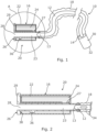
- FIGS 1 - 4C illustrate a first embodiment of a wetting mechanism 20 for use in wetting a tube 12 of a catheter 10.
- the catheter 10 includes the catheter tube 12, with the wetting mechanism 20 provided at a tip end (proximal end) 13 of the catheter tube 12 and a funnel 30 at a distal end 14 of the catheter tube 12.
- a sleeve 18 is provided between the wetting mechanism 20 and the funnel 30, enclosing the catheter tube 12 therebetween.
- the sleeve 18 is formed of a flexible material and is coupled at a first end to a housing 16 of the wetting mechanism 20 and at a second end to the funnel 30. In this way, the sleeve 18 defines an internal volume about the catheter tube 12 into which fluid may be introduced to wet the outer surface of the catheter tube 12.
- the catheter tube 12 has a tip end 13 and a distal end 14.
- the tip end 13 includes a tip for insertion of the catheter tube 12 into a canal, vessel, passageway, body cavity, etc. for removal of fluid therefrom.
- the catheter 10 comprises a male urinary catheter 10 with the tip configured for insertion into a male patient's bladder.
- the tip end 13 of the catheter tube includes an aperture 34 therein for allowing for fluid to enter the interior of the catheter tube 12.
- the distal end 14 of the catheter tube 12 is provided within the funnel 30. Specifically, the distal end 14 of the catheter tube 12 is located within the funnel 30 and opens into the funnel 30, which defines a fluid outlet 32 which serves as an outlet for discharging fluid from within the catheter tube 12.
- the catheter tube 12 itself comprises a hydrophilic coating which acts to provide a low friction outer surface of the catheter tube 12 upon application of a wetting fluid.
- the wetting mechanism 20 includes a tubular housing 16 positioned (at least initially) at a tip end 13 of the catheter tube 12.
- the housing 16 includes a holding chamber 22 which contains a volume of fluid 24 therein for wetting the catheter tube 12.
- the fluid 24 may be released from said holding chamber 22 into a wetting chamber 23 of the housing through an opening 27 within the housing 16.
- the wetting chamber 23 defines a separate tubular portion of the housing 16 through which at least a portion of the catheter tube 12 is able to be introduced and be moved therethrough. Accordingly, by releasing the fluid 24 into the wetting chamber 23, and subsequently moving the catheter tube 12 through the wetting chamber 23, an outer surface of the catheter tube 12 may be wetted using the fluid 24.
- the wetting mechanism 20 comprises a fluid release control component in the form of a plug 26.
- the plug 26 is configured to control release of the fluid 24 from the holding chamber 22 to the wetting chamber 23.
- the plug 26 is substantially cylindrical and defines an outlet 28 of the housing 16 through which, in use, the catheter tube 12 can be moved, although other profiles are equally applicable.
- the plug 26 is initially located within the wetting chamber 23 with a portion of the plug 26 blocking opening 27. This is herein referred to as a first position or first configuration of the plug 26, corresponding to a position wherein the fluid 24 is prevented from being released from the wetting chamber 23.
- a lip 29 is provided at an end of the plug 26 which defines an interaction point for the user, specifically for the user to grip the lip 29 to provide leverage for moving the plug 26.
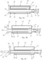
- FIGs 3A - 3B illustrate the operational use of the wetting mechanism 20 in a horizontal orientation.
- the wetting mechanism 20 is provided in the first configuration with the plug 26 in a first position blocking the opening 27 ( Figure 3A ).
- the plug 26 is partially displaced from (i.e. pulled out from) the wetting chamber 23 to a second position ( Figure 3B ). In doing so, the plug 26 is moved to a position where the opening 27 is no longer blocked, allowing the fluid 24 to be released from the holding chamber 22 into the wetting chamber 23.
- a notch 36 is provided on an outer circumferential surface of the plug 26 to define the extent to which the plug 26 can be removed from the wetting chamber 23. Specifically, the notch 36 provides a point of contact between the plug 26 and a circumferentially inwardly extending flange 38 at the end of the housing 16.
- FIGs 4A - 4C illustrate a further operational use of the wetting mechanism 20 shown in the preceding figures.
- the housing 16 is held in a vertical orientation with the plug 26 in a first position preventing release of the wetting fluid 24 from the holding chamber 22.
- the plug 26 is then pulled out from the wetting chamber 23 in the same manner as discussed above to unblock opening 27 and thereby release the wetting fluid 24 ( Figure 4B ).
- the wetting fluid 24 is released into the wetting chamber 23 and subsequently into the sleeve 18 and about the exterior surface of the catheter tube 12. In this way, the wetting fluid 24 is allowed to run along the sleeve 18, thereby wetting the catheter tube 12.
- the catheter tube 12 may then be moved through the wetting chamber 23 and past the lip 29 in the plug 26 to expose the tip end 13 for insertion by the user.
- the housing 16 acts as a gripping element for the user to direct the catheter tube 12, in use, as it is expelled through the housing 16 and introduced into the urethra.
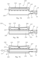
- wetting mechanism 20 A variant of wetting mechanism 20 is shown in Figures 5A - 5C . Specifically, these figures show a wetting mechanism 20' configured in substantially the same way as wetting mechanism 20 shown in the preceding Figures.
- Wetting mechanism 20' differs in that it additionally includes a wetting applicator in the form of a foam conduit 40'positioned within the wetting chamber 23'.
- the foam conduit is configured to hold fluid released into the wetting chamber 23' from the holding chamber 22'and is configured to control application of the fluid to the catheter tube 12, in use, as the catheter tube 12 is moved through the wetting chamber 23'.
- the foam conduit 40' is configured such that fluid held therein is released upon movement of the catheter tube 12 through the defined channel by virtue of the catheter tube 12 coming into contact with the foam conduit 40' and applying a pressure thereto.
- a wetting applicator of this type may advantageously ensure that the wetting fluid 24' is applied evenly across the outer surface of the catheter tube 12, and reduce the prospect of any spillage.
- FIGS 6A - 6C illustrate a further embodiment of a wetting mechanism 120 according to the invention, for wetting an outer surface of the catheter tube 12.
- the wetting mechanism 120 comprises a housing 116 positioned (at least initially) at a tip end 13 of the catheter tube 12.
- the housing 116 again includes a holding chamber 122 which contains a volume of fluid 124 therein for wetting the catheter tube 12, and a wetting chamber 123 into which the fluid 124 may be released - specifically through an opening 127 within the housing 116.
- the wetting chamber 123 again defines a separate portion of the housing 116 through which at least a portion of the catheter tube 12 is able to be introduced and be moved therethrough.
- Wetting mechanism 120 differs in that the fluid release control component in this embodiment is provided in the form of a plug 126 which must be fully removed from the chamber 123 in order to release the fluid 124 and allow the catheter tube 12 to be moved through the housing 116.
- the plug 126 is initially provided in the position shown in Figure 6A , with the plug 126 provided almost entirely within the wetting chamber 123 of the housing 116. In this position, the opening 127 in the housing 116 is blocked preventing the release of the fluid 124 from the holding chamber 122. This is referred to herein as a first position or first configuration of the plug 126. In use, the plug 126 is removed from the wetting chamber 123 to release the fluid 124 into the wetting chamber 123.
- FIGS 7A - 7C illustrate a further embodiment of a wetting mechanism 220 according to the invention, for wetting an outer surface of the catheter tube 12.
- the wetting mechanism 220 comprises a housing 216 positioned (at least initially) at a tip end 13 of the catheter tube 12.
- the housing 216 again includes a holding chamber 222 which contains a volume of fluid 224 therein for wetting the catheter tube 12, and a wetting chamber 223 into which the fluid 124 may be released - specifically through openings 227 within the housing 216.
- the wetting chamber 223 again defines a separate portion of the housing 216 through which at least a portion of the catheter tube 12 is able to be introduced and be moved therethrough.
- Wetting mechanism 220 differs in that the fluid release control component in this embodiment is provided in the form of a plug container of fluid, specifically a sachet 226 which must be ruptured in order to release the fluid 224 therefrom and into the wetting chamber 223.
- the sachet 226 is initially provided in the configuration shown in Figure 7A - i.e. intact, with the fluid contained therein.
- the sachet 226 is ruptured through a user applying an external force to the housing 216, i.e. by squeezing the housing 216 (as shown figuratively in Figure 7B ), which may be formed of a deformable material, or with a deformable region that can be squeezed.
- Rupture of the sachet 226 causes the fluid contained therein to be released into the wetting chamber 223 through openings 227 provided within the housing 216.
- the catheter tube 12 may then be moved through the wetting chamber 223 through an outlet 128 at a distal end of the housing 216 to both wet the outer surface of the catheter tube 12 expose the tip end 13 for insertion by the user.
- the housing 216 acts as a gripping element for the user to direct the catheter tube 12, in use.
- wetting mechanism 220 differs in that it additionally includes a wetting applicator in the form of a foam conduit 240'.
- the foam conduit 240' is configured to hold fluid released thereon from the holding chamber 222' and is configured to control application of the fluid to the catheter tube 12, in use, as the catheter tube 12 is moved through the housing 216'.
- Wetting mechanism 220' functions in essentially the same way as wetting mechanism 220, with a fluid release control component provided in the form of a rupturable sachet 226' controlling the release of the wetting fluid 224'.
- rupturing the sachet 226' causes the fluid 224' contained therein to be released onto the foam conduit 240' which stores the fluid 224' for subsequent application to the catheter tube 12.
- the sachet 226' defines the holding chamber 222' with the foam conduit 240' defining the wetting chamber 223' through which the catheter tube 12 may be moved, in use.
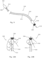
- Figures 9 - 10B illustrate further embodiments of a catheter 310 and wetting mechanism 320 operable to wet a tube 312 of the catheter 310, in use.
- the catheter 310 includes the catheter tube 312, with the wetting mechanism 320 provided at a tip end 313 of the catheter tube 312 and a funnel 330 at a distal end 314 of the catheter tube 312.
- a sleeve 318 is provided between the wetting mechanism 320 and the funnel 330, enclosing the catheter tube 12 therebetween.
- the tip end 313 of the catheter 310 includes a tip for insertion of the catheter tube 312 into a canal, vessel, passageway, body cavity, etc. for removal of fluid therefrom.
- the catheter 310 comprises a male urinary catheter 310 with the tip configured for insertion into a male patient's bladder.
- the distal end 314 of the catheter tube 312 is provided within the funnel 330.
- the distal end 314 of the catheter tube 312 is located within the funnel 330 and opens into the funnel 330 which defines a fluid outlet 332 which serves as an outlet for discharging fluid from within the catheter tube 312.
- the funnel 330 is shaped to aid the user's control over the direction of discharge of the fluid from the catheter tube 312.
- the catheter tube 312 itself comprises a hydrophilic coating which acts to provide a low friction outer surface of the catheter tube 312 upon application of a wetting fluid.
- the wetting mechanism 320 is similar in configuration to wetting mechanism 20 described herein, and may be of the nature of, with the same features as, any of the embodiments of figures 1 - 5C or 7A - 8C . It includes a housing 316 positioned (at least initially) at the tip end 313 of the catheter tube 312.
- the housing 316 includes a holding chamber (not shown) which contains a volume of fluid therein for wetting the catheter tube 312. In use, and as is described herein, the fluid may be released from said holding chamber into a wetting chamber (not shown) of the housing 316 under the operation of a plug 326.
- an outer surface of the catheter tube 312 may be wetted using the fluid.
- the plug 326 is moveable from the position shown in Figure 10A (a first position) to the position shown in Figure 10B (a second position) to release the fluid from the holding chamber. Specifically, movement of the plug 326 between these positions may unblock an opening within the housing 316 or rupture a sachet, for example, to allow for the fluid to be released from the holding chamber.
- the plug 326 comprises a conical cross section, with a ridged exterior surface defining an interaction surface for the user.
- the housing 316 is also substantially conical in profile, and is positioned in such a way to define an hourglass-shaped configuration of the housing 316 and plug 326.
- This arrangement is particularly beneficial as it may allow for operation of the plug 326 using only one hand, as shown in Figures 10A and 10B .
- the user may grip the housing 316 and plug 326 between their thumb and forefinger, before using their thumb to push or "pop" the plug 326 upwards (in the orientation shown in the Figures) to release the fluid.
- the conical plug 326 has a cup like end, which eases location of the housing 316 over the tip of the penis to aid insertion of the catheter tube 312 into the urethra, in use.
- the fluid release control component e.g. the plug 26, 126, 326
- the fluid release control component may alternatively be rotatable between first and second positions/configurations to control the release of the wetting fluid.
- rotation of the plug 26, 126, 326 may align an opening in the plug to unblock an opening 27, 127 or valve in the housing 16, 116, 316 allowing for the release of the wetting fluid.
- the wetting mechanism may be configured to retain the plug 26 in the first and/or second position.
- the wetting mechanism 20 may be configured to retain the plug 26 in the first position, preventing release of the fluid from the holding chamber 22 unless positively acted on by a user.
- This may be provided, for example, in the form of an abutment between a frangible portion on the plug 26 and/or on the housing 16 configured to break upon application of a force by the user. In this way, the plug 26 may "snap" or "click” in overcoming said abutment to provide tactile and/or audible feedback for the user.
- the wetting mechanism 20 may be configured such that, in the second position at least a portion of the plug 26 is provided in an abutting relationship with a further component of the wetting mechanism (e.g. the housing 16) preventing further movement of the plug 26 and thereby preventing the plug 26 being returned to the first position.
- a further component of the wetting mechanism e.g. the housing 16
- the wetting mechanism 20, 20', 120, 220, 320 of the invention may include both a plug (e.g. plug 26) and rupturable container (e.g. sachet 226).
- the wetting mechanism may be configured such that the container may be ruptured through compression on the container upon (at least partial) withdrawal of the plug, or upon rotation of the plug.
- the housing may include a valve arrangement or the like preventing the wetting fluid from being released from the housing.
- the housing can include a valve arrangement at an inlet and/or an outlet.
- the valve arrangement may be configured to allow the catheter tube 12, 312 to be moved therethrough.
- the fluid release control component e.g. the plug 26, 126, 326 can be configured to prevent insertion of the catheter tube into and/or through the wetting chamber when in the first position - i.e. before the fluid is released from the holding chamber to the wetting chamber. This may, for example, involve the fluid release control component at least partially blocking an inlet for the catheter tube 12, 312.
- the wetting applicator can comprise a sponge or wicking material, operable to absorb the wetting fluid, in use, or may comprise a baffle arrangement.
Landscapes
- Health & Medical Sciences (AREA)
- Life Sciences & Earth Sciences (AREA)
- Biophysics (AREA)
- Pulmonology (AREA)
- Engineering & Computer Science (AREA)
- Anesthesiology (AREA)
- Biomedical Technology (AREA)
- Heart & Thoracic Surgery (AREA)
- Hematology (AREA)
- Animal Behavior & Ethology (AREA)
- General Health & Medical Sciences (AREA)
- Public Health (AREA)
- Veterinary Medicine (AREA)
- Epidemiology (AREA)
- Urology & Nephrology (AREA)
- Media Introduction/Drainage Providing Device (AREA)
- External Artificial Organs (AREA)
- Materials For Medical Uses (AREA)
Abstract
Description
- The present invention relates to a wetting mechanism for a catheter (e.g. a urinary catheter) for wetting a tube of the catheter, in use. The invention extends to a catheter comprising the wetting mechanism and a method for wetting a catheter tube.
- A catheter is a medical device comprising a hollow catheter tube designed for insertion into canals, vessels, passageways or body cavities to permit injection, drainage or withdrawal of fluids or substances therefrom, or to ensure said canals, vessels, passageways etc. remain open. Urinary catheters are designed for use for insertion into a user's bladder via the urethra to drain the bladder.
- To maximise comfort and minimise the risk of trauma and/or infection, an outer surface of the catheter tube is typically wetted using a wetting fluid prior to insertion by the user. In further developments, the catheter tube itself comprises, is integrated with or is coated with a hydrophilic component (e.g. a hydrophilic polymer) which serves to reduce friction further upon application of the wetting fluid.
- Some catheters may be supplied pre-wetted in a packaging, for instance, where the catheter is at least partially submerged within wetting fluid within the packaging. However, such arrangements suffer in that components of the catheter other than the catheter tube such as a gripper element or funnel can also become wetted. This has a detrimental effect of the experience of the user where it may become difficult to hold and direct the catheter tube as required. This is particularly problematic where the user is performing self-catheterisation. Further, having the catheter submerged may effectively reduce the shelf-life of the catheter due to long-term exposure of components of the catheter to moisture.
- It is therefore seen advantageous to provide a catheter which may be wetted at or immediately prior to the point of use.
- In an attempt to address this, some catheters are provided in packaging which includes a rupturable container or sachet within the packaging which a user may burst to release the wetting fluid. Typically, this involves the user squeezing the packaging to cause the container/sachet to break. However, such arrangements experience similar problems to those discussed above where the wetting fluid is allowed to come into contact with other components of the catheter.
- It would therefore be advantageous to provide a catheter which includes a means of supplying a wetting fluid solely to the catheter tube to improve user experience.
- It is an aim of an embodiment or embodiments of the invention to overcome or at least partially mitigate one or more problems with the prior art.
- According to an aspect of the invention there is provided a wetting mechanism for wetting a tube of a catheter, the wetting mechanism comprising a housing having: a holding chamber for containing a volume of fluid therein; and a wetting chamber into which at least a portion of the catheter tube is able to be introduced and be moved therethrough; and wherein the wetting mechanism comprises a fluid release control component for controlling release of the fluid from the holding chamber to the wetting chamber.
- According to an aspect of the invention there is provided a wetting mechanism for wetting a tube of a catheter, the wetting mechanism comprising: a housing configured to be positioned initially at or proximal to the tip end of the catheter tube, and wherein the housing comprises: a holding chamber for containing a volume of fluid therein; and a wetting chamber into which at least a portion of the catheter tube is able to be introduced and be moved therethrough to move at least a portion of the catheter tube through the wetting chamber, in use; and wherein the wetting mechanism comprises a fluid release control component for controlling release of the fluid from the holding chamber to the wetting chamber.
- Advantageously, controlling the release of the fluid from a holding chamber where it is held out of contact with other components of the catheter system overcomes issues with the prior art, particularly where catheters may be disadvantageously submerged in wetting fluid prior to use. It may also improve the shelf life of the catheter by reducing the exposure of most of the components of the catheter to moisture until (or as close as possible to) the point of use. Further, controlling the release of the wetting fluid into a wetting chamber through which the catheter tube may be moved through provides greater control over the application of the wetting fluid to the external surface of the catheter tube. This may ensure the whole surface of the catheter tube is adequately wetted prior to use by the user.
- Optional features set out below may apply to any aspect of the invention as appropriate.
- The fluid release control component may comprise a first configuration wherein it prevents release of the fluid from the holding chamber to the wetting chamber. The fluid release control component may comprise a second configuration wherein it allows release of the fluid from the holding chamber to the wetting chamber. The fluid release control component may be moveable between the first and second configurations. For example, in some embodiments the fluid release control component may be linearly moveable between the first and second configurations. In other embodiments the fluid release control component may be operable to rotate between first and second configurations for controlling the flow of fluid from the holding chamber to the wetting chamber.
- In some embodiments the fluid release control component comprises a plug. The plug may be linearly moveable within the wetting mechanism between first and second positions. The plug may be rotatable between first and second angular positions. For example, the plug may be threaded, and may be provided within the wetting mechanism through interaction with a complementary threaded surface of the wetting mechanism. The first and second (optionally angular) positions of the plug may correspond to first and second configurations of the fluid release control component.
- One particularly preferred embodiment provides a wetting mechanism for wetting a tube of a catheter, the wetting mechanism comprising: a housing configured to be positioned initially at or proximal to the tip end of the catheter tube, and wherein the housing comprises: a holding chamber for containing a volume of fluid therein; and a wetting chamber into which at least a portion of the catheter tube is able to be introduced and be moved therethrough to move at least a portion of the catheter tube through the wetting chamber, in use; and wherein the wetting mechanism comprises a fluid release control component for controlling release of the fluid from the holding chamber to the wetting chamber; wherein the fluid release control component comprises a first configuration wherein it prevents release of the fluid from the holding chamber to the wetting chamber and a second configuration wherein it allows release of the fluid from the holding chamber to the wetting chamber; wherein the fluid release control component comprises a plug which is linearly moveable within the wetting mechanism between first and second positions corresponding to first and second configurations of the fluid release control component.
- In embodiments, the plug may be configured to be at least partly withdrawn from the wetting mechanism. The plug may, at least initially be positioned within the wetting chamber of the wetting mechanism. In such embodiments, the plug may be configured to be at least partly withdrawn from the wetting chamber to cause release of the fluid from the holding chamber into the wetting chamber. The plug may be configured to be only partly withdrawn from the wetting mechanism - i.e. it cannot be fully withdrawn from the wetting mechanism. It may remain attached or otherwise coupled to the housing whether in the first or second position. In further embodiments, the plug may be configured such that it can be fully withdrawn from the wetting mechanism. For example, in some embodiments the plug may initially be positioned within the wetting chamber and may be fully withdrawn from the wetting chamber, in use, to cause release of the fluid from the holding chamber to the wetting chamber.
- Another particularly preferred embodiment provides a wetting mechanism for wetting a tube of a catheter, the wetting mechanism comprising: a housing configured to be positioned initially at or proximal to the tip end of the catheter tube, and wherein the housing comprises: a holding chamber for containing a volume of fluid therein; and a wetting chamber into which at least a portion of the catheter tube is able to be introduced and be moved therethrough to move at least a portion of the catheter tube through the wetting chamber, in use; and wherein the wetting mechanism comprises a fluid release control component for controlling release of the fluid from the holding chamber to the wetting chamber; wherein the fluid release control component comprises a first configuration wherein it prevents release of the fluid from the holding chamber to the wetting chamber and a second configuration wherein it allows release of the fluid from the holding chamber to the wetting chamber; wherein the fluid release control component comprises a plug which is linearly moveable within the wetting mechanism between first and second positions corresponding to first and second configurations of the fluid release control component; wherein the plug is configured to be at least partly withdrawn from the wetting mechanism to cause release of fluid from the holding chamber into the wetting chamber.
- Another particularly preferred embodiment provides a wetting mechanism for wetting a tube of a catheter, the wetting mechanism comprising: a housing configured to be positioned initially at or proximal to the tip end of the catheter tube, and wherein the housing comprises: a holding chamber for containing a volume of fluid therein; and a wetting chamber into which at least a portion of the catheter tube is able to be introduced and be moved therethrough to move at least a portion of the catheter tube through the wetting chamber, in use; and wherein the wetting mechanism comprises a fluid release control component for controlling release of the fluid from the holding chamber to the wetting chamber; wherein the fluid release control component comprises a first configuration wherein it prevents release of the fluid from the holding chamber to the wetting chamber and a second configuration wherein it allows release of the fluid from the holding chamber to the wetting chamber; wherein the fluid release control component comprises a plug which is linearly moveable within the wetting mechanism between first and second positions corresponding to first and second configurations of the fluid release control component; wherein the plug is, at least initially, positioned within the wetting chamber of the wetting mechanism and is configured to be at least partly withdrawn from the wetting chamber to cause release of the fluid from the holding chamber into the wetting chamber.
- Another particularly preferred embodiment provides a wetting mechanism for wetting a tube of a catheter, the wetting mechanism comprising: a housing configured to be positioned initially at or proximal to the tip end of the catheter tube, and wherein the housing comprises: a holding chamber for containing a volume of fluid therein; and a wetting chamber into which at least a portion of the catheter tube is able to be introduced and be moved therethrough to move at least a portion of the catheter tube through the wetting chamber, in use; and wherein the wetting mechanism comprises a fluid release control component for controlling release of the fluid from the holding chamber to the wetting chamber; wherein the fluid release control component comprises a first configuration wherein it prevents release of the fluid from the holding chamber to the wetting chamber and a second configuration wherein it allows release of the fluid from the holding chamber to the wetting chamber; wherein the fluid release control component comprises a plug which is linearly moveable within the wetting mechanism between first and second positions corresponding to first and second configurations of the fluid release control component; wherein the plug is, at least initially, positioned within the wetting chamber of the wetting mechanism and is configured to be at least partly withdrawn from the wetting chamber to cause release of the fluid from the holding chamber into the wetting chamber; and wherein the plug is configured such that it cannot be fully withdrawn from the wetting mechanism.
- The wetting mechanism may be configured such that, in use, at least partly withdrawing the plug from the wetting mechanism causes the opening of one or more fluid outlets in the holding chamber. The one or more fluid outlets may provide a fluid communication between the holding chamber and the wetting chamber such that, in use, opening of said fluid outlet(s) may allow fluid to be released from within the holding chamber into the wetting chamber.
- The wetting mechanism may be configured to retain the plug in the first and/or second position.
- For example, in some embodiments the wetting mechanism may be configured to retain the plug in the first position, preventing release of the fluid from the holding chamber, unless positively acted on by a user. Advantageously, this may prevent or at least reduce the likelihood of fluid being release from the holding chamber and/or the catheter tube being exposed prematurely. This may ensure that the catheter tube is wetted at or as close as possible to the point of use to ensure the surface of the catheter tube is fully wetted. In such embodiments, the plug may be biased to the first position, and the user may be required to act against said bias to move the plug to the second position. At least a portion of the plug may abut a further component of the wetting mechanism, e.g. a lip, projection or the like from a surface of the housing preventing movement of the plug from the first position unless acted on by a user. The abutment may be provided between a frangible portion on the plug and/or on the housing configured to break upon application of a force by the user. For example, the abutment between the plug and the further component may be configured such that application of a force (e.g. the user pulling the plug away from the housing), may be sufficient to overcome said abutment, allowing the plug to be moved to the second position. The plug may "snap" or "click" in overcoming said abutment to provide tactile and/or audible feedback for the user.
- In embodiments, the wetting mechanism may be configured to retain the plug in the second position, preventing the plug being returned to the first position. Advantageously, once activated, the wetting mechanism may be configured to be retained in a "used" configuration, ensuring that the catheter and wetting mechanism cannot be returned to a configuration which appears as though it has not been used - i.e. a configuration which suggests that the wetting mechanism may still be operable to wet the catheter tube (which may not be the case). This may prevent or at least reduce the likelihood of the user re-using the catheter (either mistakenly or intentionally). In such embodiments, the wetting mechanism may be configured such that, in the second configuration at least a portion of the plug is provided in an abutting relationship with a further component of the wetting mechanism (e.g. the housing) preventing further movement of the plug.
- The fluid release control component may, in some embodiments, comprise a container. The container may be positioned within the holding chamber. The container may house the fluid. The container may comprise one of a sachet, blister pack, or capsule, for example.
- The first configuration of the fluid release control component may correspond to a configuration wherein the container is intact, having the fluid contained therein. The second configuration of the fluid release control component may correspond to a configuration wherein the container has ruptured or has otherwise been opened to release fluid therefrom.
- The wetting mechanism may be configured such that the container may be ruptured or otherwise opened, in use, through user action on the housing itself. For example, in some embodiments the housing is formed at least partly from a flexible, compressible and/or resilient material. In such embodiments, the wetting mechanism may be configured such that the container may be ruptured or otherwise opened upon a user compressing, bending and/or flexing the housing.
- In further embodiments, the wetting mechanism may comprise a fluid release control component in the form of a plug, in combination with the container. In such embodiments, the wetting mechanism may be configured such that the container may be ruptured or otherwise opened, in use, through movement of the plug. For example, the wetting mechanism may be configured such that the container is compressed upon (at least partial) withdrawal of the plug, or upon rotation of the plug.
- The tip end of the catheter tube may, at least initially, be disposed outside the wetting chamber. In such embodiments, the wetting mechanism may be configured such that the tip end of the catheter tube is able to be introduced into the wetting chamber and moved therethrough, in-use. For example, the wetting chamber may comprise an inlet through which the catheter tube is able to be introduced into the wetting chamber. In some embodiments the wetting chamber may comprise an outlet through which the catheter tube is able to exit the wetting chamber.
- In some embodiments the wetting mechanism may be configured such that fluid released into the wetting chamber from the holding chamber is retained therein for wetting the catheter tube as it is moved therethrough, in use. For example, in some embodiments the wetting mechanism may comprise a valve arrangement. The valve arrangement may be provided at the inlet and/or outlet of the wetting chamber in order to retain fluid contained therein. The valve arrangement may be configured such that the catheter may be moved therethrough, in use.
- In some embodiments the wetting mechanism is configured to be coupled to a sleeve. The wetting mechanism may be configured to be coupled to a sleeve which in turn is able to couple the wetting mechanism to a funnel, e.g. a funnel provided at or integrally formed with the distal end of the catheter tube. The wetting mechanism may be configured such that fluid released into the wetting chamber is able to flow into and along the sleeve to wet the catheter tube. For example, the wetting chamber may include an opening therein allowing fluid within the wetting chamber to flow into and along a coupled sleeve. The opening may be the inlet for the catheter tube.
- In some embodiments the fluid release control component may be configured to prevent insertion of the catheter tube into and/or through the wetting chamber. For example, in some embodiments the fluid release control component may be configured to prevent insertion of the catheter tube into and/or through the wetting chamber in the first configuration - i.e. before the fluid is released from the holding chamber to the wetting chamber. Advantageously, preventing the catheter tube from being prematurely inserted and/or moved through the wetting chamber may ensure that the catheter tube is unable to be used without application of the wetting fluid. To achieve this, the fluid release control component may be configured to at least partially block an inlet for the catheter tube when in the first configuration. For example, in some embodiments a portion of the fluid release control component may be at least partially received within the inlet for the catheter tube, preventing insertion of the catheter tube into the wetting chamber. The portion of the fluid release control component may comprise a flexible, compressible and/or resilient material which may be compressed within the inlet for the catheter tube with the fluid release control component in the first configuration.
- The fluid release control component may be configured such that switching (e.g. moving) the fluid release control component to a second configuration may allow insertion of the catheter tube into and/or through the wetting chamber in the second configuration. In other words, switching/moving the fluid release control component to the second configuration may both act to release fluid from within the holding chamber and remove any block on the catheter tube being inserted and/or moved through the wetting chamber.
- In some embodiments the wetting mechanism comprises a wetting applicator. The wetting applicator may be positioned within the wetting chamber. The wetting applicator may be configured to hold fluid released into the wetting chamber from the holding chamber. The wetting applicator may be configured to control application of the fluid to the catheter tube, in use, as the catheter tube is moved through the wetting chamber.
- One particularly preferred embodiment provides a wetting mechanism for wetting a tube of a catheter, the wetting mechanism comprising: a housing configured to be positioned initially at or proximal to the tip end of the catheter tube, and wherein the housing comprises: a holding chamber for containing a volume of fluid therein; and a wetting chamber into which at least a portion of the catheter tube is able to be introduced and be moved therethrough to move at least a portion of the catheter tube through the wetting chamber, in use; and wherein the wetting mechanism comprises a fluid release control component for controlling release of the fluid from the holding chamber to the wetting chamber; the wetting mechanism comprising a wetting applicator positioned within the wetting chamber configured to hold fluid released into the wetting chamber from the holding chamber.
- Another particularly preferred embodiment provides a wetting mechanism for wetting a tube of a catheter, the wetting mechanism comprising: a housing configured to be positioned initially at or proximal to the tip end of the catheter tube, and wherein the housing comprises: a holding chamber for containing a volume of fluid therein; and a wetting chamber into which at least a portion of the catheter tube is able to be introduced and be moved therethrough to move at least a portion of the catheter tube through the wetting chamber, in use; and wherein the wetting mechanism comprises a fluid release control component for controlling release of the fluid from the holding chamber to the wetting chamber; the wetting mechanism comprising a wetting applicator positioned within the wetting chamber configured to hold fluid released into the wetting chamber from the holding chamber, wherein the wetting applicator is configured to control application of the fluid to the catheter tube, in use, as the catheter tube is moved through the wetting chamber.
- The wetting applicator may comprise an absorbent material. For example, in some embodiments the wetting applicator comprises a sponge, foam or wicking material, operable to absorb the wetting fluid, in use. In further embodiments, the wetting applicator may comprise a baffle arrangement. The baffle arrangement may define a plurality of subregions of the wetting applicator each configured to hold a portion of the fluid held within the wetting applicator.
- The wetting applicator may define a channel within the wetting chamber. The wetting applicator may define a channel within the wetting chamber through which the catheter tube is able to be moved through, in use. The wetting mechanism may be configured such that the catheter tube is moved in contact with the wetting applicator as it is moved through the wetting chamber (e.g. along the channel defined by the wetting applicator. In embodiments, the wetting applicator may be configured such that fluid held within the wetting applicator is able to be released, and preferably is automatically released, therefrom upon movement of the catheter tube through the wetting chamber.
- Another particularly preferred embodiment provides a wetting mechanism for wetting a tube of a catheter, the wetting mechanism comprising: a housing configured to be positioned initially at or proximal to the tip end of the catheter tube, and wherein the housing comprises: a holding chamber for containing a volume of fluid therein; and a wetting chamber into which at least a portion of the catheter tube is able to be introduced and be moved therethrough to move at least a portion of the catheter tube through the wetting chamber, in use; and wherein the wetting mechanism comprises a fluid release control component for controlling release of the fluid from the holding chamber to the wetting chamber; the wetting mechanism comprising a wetting applicator positioned within the wetting chamber configured to hold fluid released into the wetting chamber from the holding chamber, wherein the wetting applicator is configured to control application of the fluid to the catheter tube, in use, as the catheter tube is moved through the wetting chamber; wherein the wetting applicator defines a channel within the wetting chamber through which the catheter tube is able to be moved through, in use, and the wetting applicator is configured such that fluid held within the wetting applicator is able to be released therefrom upon movement of the catheter tube through said channel.
- The holding chamber may be configured to hold up to 0.25ml, or up to 0.5ml, or up to 0.75ml, or up to 1.0ml, or up to 1.5ml, or up to 2.0ml, or up to 2.5ml, or up to 3.0ml, or up to 4.0ml, or up to 5.0ml, or up to 7.5ml, or up to 10ml of wetting fluid, for example.
- In embodiments, the housing may form a gripping element of the catheter. In use, the gripping element may be used by a user to control application of the catheter. For example, the gripping element can be used to hold the catheter tube close to the urethra to help a user guide the catheter tube without having to touch the tube itself. In embodiments, the housing may comprise a conical profile. A conical profile may be advantageous where there housing forms a gripping element of the catheter.
- In embodiments wherein the fluid release control component comprises a plug, the plug may comprise a conical profile. The plug may comprise a hollow or substantially hollow interior. Where combined with a conical profile, such a plug may form a cup shape element which may assist a user with locating the catheter tube, in use. The cup can, for example, be used to locate the housing over the tip of a penis such that the catheter tube can be easily inserted into the urethra immediately after wetting.
- In some embodiments, the housing and the plug both comprise a conical profile. In such embodiments, the wetting mechanism may be configured such that, together, the housing and the plug form a substantially hourglass-shaped profile. An hourglass-shaped profile may be particularly advantageous in that it may allow the user to operate the wetting mechanism - i.e. to remove (or at least partially remove) the plug from the housing using only one hand.
- According to an aspect of the invention there is provided a catheter, comprising: a catheter tube having a tip end and a distal end; and the wetting mechanism of any preceding aspect operably coupled at or proximal to the tip end of the catheter tube for wetting the catheter tube, in use.
- The catheter may comprise a funnel. The funnel may be provided at or proximal to the distal end of the catheter tube. The funnel may comprise a fluid outlet for the discharge of fluid from within the catheter tube.
- In embodiments, the catheter comprises a sleeve. The sleeve may be positioned about the catheter tube. In embodiments, the sleeve may define an internal volume about at least a portion of the catheter tube. The sleeve may comprise a flexible material. The sleeve may be thin and readily crumpled. For example, the sleeve may be formed of a film of plastics material, which may be low-density polyethylene, for example.
- The sleeve may be coupled to the wetting mechanism. For example, the sleeve may be coupled at a first end to the wetting mechanism. In such embodiments, the sleeve may be coupled at a second, opposing end to a funnel at or proximal to a distal end of the catheter tube. In this way, the sleeve may define an internal volume about the catheter tube between the wetting mechanism at or proximal to the tip end of the catheter tube, and a funnel at or proximal to a distal end of the catheter tube.
- The catheter may be configured such that fluid released within the wetting chamber of the wetting mechanism is able to flow into and along the sleeve to wet the catheter tube, in use. For example, in some embodiments the housing of the wetting mechanism comprises an aperture or opening therein allowing fluid within the wetting chamber to flow into the sleeve.
- The catheter may comprise a urinary catheter. The catheter may comprise a female urinary catheter, but is preferably a male urinary catheter. The catheter may comprise a single-use catheter. The catheter may comprise an intermittent urinary catheter.
- The catheter tube may have a length of up to (and possibly upwards) of 35cm. The catheter tube may be up to or at least 20cm, up to or at least 25cm, up to or at least 30cm, up to or at least 35cm, or up to or at least 40cm, in length, for example. In embodiments, the catheter tube may be more than 40cm in length. In preferred embodiments, the catheter tube is between 25-35cm, in length. Male catheters typically have a catheter tube of such lengths and would be less suited to mechanisms which wet the catheter tube from the distal end (as opposed to the tip end as in the present invention), as the fluid may not adequately cover the entire length of the tube. This potentially results in the tip end being wetted last (or not at all if there is insufficient fluid), which is undesirable since the tip end will be introduced into the urethra first and is hence most likely to cause injury if inadequately wetted before use. Accordingly, the invention is particularly suited to male catheters.
- The catheter tube may comprise, may be integrated with, or may be coated with a hydrophilic component. The hydrophilic component may be configured to provide a low friction surface (e.g. outer surface) of the catheter tube upon application of the wetting fluid. The hydrophilic component may comprise a hydrophilic polymer, for example.
- According to an aspect of the invention there is provided a sealed packaged catheter according to the preceding aspect of the invention, wherein the wetting mechanism is operably coupled at or proximal to the tip end of the catheter tube within the sealed package.
- According to an aspect of the invention there is provided a method for wetting a tube of a catheter using the wetting mechanism of any aspect described herein, the method comprising: operating the fluid release control component to cause the release of fluid from the holding chamber into the wetting chamber; and introducing the tip end of the catheter tube into the wetting chamber and moving it therethrough, thereby wetting the at least a portion of an outer surface of the catheter tube.
- Operating the fluid release control component may comprise moving the fluid release control component from a first configuration wherein it prevents release of the fluid from the holding chamber to the wetting chamber to a second configuration wherein it allows release of the fluid from the holding chamber to the wetting chamber.
- In some embodiments the fluid release control component comprises a plug and method may comprise at least partly withdrawing the plug from the wetting mechanism to operate the fluid release control component. The method may comprise at least partly withdrawing the plug from the wetting chamber to cause release of the fluid from the holding chamber into the wetting chamber. The method may comprise fully withdrawing the plug from the wetting mechanism to cause release of the fluid from the holding chamber to the wetting chamber.
- The fluid release control component may comprise a container, such as a sachet, blister pack or capsule, for example, and the method may comprise rupturing or been opening the container to release fluid therefrom. The method may comprise compressing, bending and/or flexing the housing to rupture or otherwise open the container.
- In further embodiments, the wetting mechanism may comprise a fluid release control component in the form of a plug, in combination with the container, and the method may comprise at least partly withdrawing the plug from the wetting mechanism to rupture or otherwise open the container. For example, the method may comprise compressing the container within the holding chamber upon at least partial withdrawal of the plug from the wetting mechanism.
- In order that the invention may be more clearly understood one or more embodiments thereof will now be described, by way of example only, with reference to the accompanying drawings, of which:
- Figure 1
- is a schematic overview of a first embodiment of the invention;
- Figure 2
- is a side cross-sectional schematic view of section A in
Figure 1 ; - Figures 3A - 3C
- are a series of cross-sectional schematic views illustrating the operational use of the embodiment of the preceding Figures;
- Figures 4A - 4C
- are a series of further cross-sectional schematic views illustrating a further operational use of the embodiment shown in the preceding Figures;
- Figures 5A - 5C
- are a series of cross-sectional schematic views illustrating the operational use of a second embodiment of the invention;
- Figures 6A - 6C
- are a series of cross-sectional schematic views illustrating the operational use of a third embodiment of the invention;
- Figures 7A - 7C
- are a series of cross-sectional schematic views illustrating the operational use of a fourth embodiment of the invention;
- Figures 8A - 8C
- are a series of cross-sectional schematic views illustrating the operational use of a fifth embodiment of the invention;
- Figure 9
- is a perspective view of a sixth embodiment of the invention; and
- Figures 10A - 10B
- are a pair of side views illustrating the operational use of the embodiment shown in
Figure 9 . - In general, the present invention relates to a
catheter 10, 310, and specifically to awetting mechanism tube catheter 10, 310, in use. - The Figures illustrate a series of embodiments of the invention. Where equivalent components are present between embodiments, like reference numerals have been used.
-
Figures 1 - 4C illustrate a first embodiment of awetting mechanism 20 for use in wetting atube 12 of a catheter 10. - The catheter 10 includes the
catheter tube 12, with thewetting mechanism 20 provided at a tip end (proximal end) 13 of thecatheter tube 12 and a funnel 30 at a distal end 14 of thecatheter tube 12. Asleeve 18 is provided between the wettingmechanism 20 and the funnel 30, enclosing thecatheter tube 12 therebetween. Here, thesleeve 18 is formed of a flexible material and is coupled at a first end to ahousing 16 of thewetting mechanism 20 and at a second end to the funnel 30. In this way, thesleeve 18 defines an internal volume about thecatheter tube 12 into which fluid may be introduced to wet the outer surface of thecatheter tube 12. - As mentioned above, the
catheter tube 12 has atip end 13 and a distal end 14. Thetip end 13 includes a tip for insertion of thecatheter tube 12 into a canal, vessel, passageway, body cavity, etc. for removal of fluid therefrom. Here, the catheter 10 comprises a male urinary catheter 10 with the tip configured for insertion into a male patient's bladder. Thetip end 13 of the catheter tube includes anaperture 34 therein for allowing for fluid to enter the interior of thecatheter tube 12. The distal end 14 of thecatheter tube 12 is provided within the funnel 30. Specifically, the distal end 14 of thecatheter tube 12 is located within the funnel 30 and opens into the funnel 30, which defines a fluid outlet 32 which serves as an outlet for discharging fluid from within thecatheter tube 12. Thecatheter tube 12 itself comprises a hydrophilic coating which acts to provide a low friction outer surface of thecatheter tube 12 upon application of a wetting fluid. - The wetting
mechanism 20 includes atubular housing 16 positioned (at least initially) at atip end 13 of thecatheter tube 12. Thehousing 16 includes a holdingchamber 22 which contains a volume offluid 24 therein for wetting thecatheter tube 12. In use, and as is described herein, the fluid 24 may be released from said holdingchamber 22 into a wettingchamber 23 of the housing through anopening 27 within thehousing 16. The wettingchamber 23 defines a separate tubular portion of thehousing 16 through which at least a portion of thecatheter tube 12 is able to be introduced and be moved therethrough. Accordingly, by releasing the fluid 24 into the wettingchamber 23, and subsequently moving thecatheter tube 12 through the wettingchamber 23, an outer surface of thecatheter tube 12 may be wetted using thefluid 24. - The wetting
mechanism 20 comprises a fluid release control component in the form of aplug 26. As is described herein, theplug 26 is configured to control release of the fluid 24 from the holdingchamber 22 to the wettingchamber 23. In the illustrated embodiment, theplug 26 is substantially cylindrical and defines anoutlet 28 of thehousing 16 through which, in use, thecatheter tube 12 can be moved, although other profiles are equally applicable. As shown inFigures 1-3A , theplug 26 is initially located within the wettingchamber 23 with a portion of theplug 26 blockingopening 27. This is herein referred to as a first position or first configuration of theplug 26, corresponding to a position wherein the fluid 24 is prevented from being released from the wettingchamber 23. Alip 29 is provided at an end of theplug 26 which defines an interaction point for the user, specifically for the user to grip thelip 29 to provide leverage for moving theplug 26. -
Figures 3A - 3B illustrate the operational use of thewetting mechanism 20 in a horizontal orientation. As set out above, initially thewetting mechanism 20 is provided in the first configuration with theplug 26 in a first position blocking the opening 27 (Figure 3A ). In order to activate thewetting mechanism 20, theplug 26 is partially displaced from (i.e. pulled out from) the wettingchamber 23 to a second position (Figure 3B ). In doing so, theplug 26 is moved to a position where theopening 27 is no longer blocked, allowing the fluid 24 to be released from the holdingchamber 22 into the wettingchamber 23. Spillage (or at least major spillage) of fluid through theoutlet 28 of thehousing 16 is prevented due to the relatively small volume of wettingfluid 24 provided (approximatley 2.5ml), and the surface tension of the fluid 24 itself. Anotch 36 is provided on an outer circumferential surface of theplug 26 to define the extent to which theplug 26 can be removed from the wettingchamber 23. Specifically, thenotch 36 provides a point of contact between theplug 26 and a circumferentially inwardly extendingflange 38 at the end of thehousing 16. - Subsequently, the
catheter tube 12 may be moved through the wettingchamber 23, bringing thecatheter tube 12 into contact with the wettingfluid 24 and hence wetting an outer surface of thecatheter tube 12. Once thetip end 13 of thecatheter tube 12 is moved beyond thelip 29 in theplug 26, and out through anoutlet 28 of thehousing 16, thetip end 13 then becomes exposed for insertion by the user. Thehousing 16 then acts as a gripping element for the user to direct thecatheter tube 12, in use, as the user may then use thehousing 16 to easily direct the exposedtip end 13 of thecatheter tube 12 without contacting thetube 12 directly. -
Figures 4A - 4C illustrate a further operational use of thewetting mechanism 20 shown in the preceding figures. Specifically, starting atFigure 4A , thehousing 16 is held in a vertical orientation with theplug 26 in a first position preventing release of the wettingfluid 24 from the holdingchamber 22. Theplug 26 is then pulled out from the wettingchamber 23 in the same manner as discussed above to unblockopening 27 and thereby release the wetting fluid 24 (Figure 4B ). With thehousing 16 held in this orientation, the wettingfluid 24 is released into the wettingchamber 23 and subsequently into thesleeve 18 and about the exterior surface of thecatheter tube 12. In this way, the wettingfluid 24 is allowed to run along thesleeve 18, thereby wetting thecatheter tube 12. Thecatheter tube 12 may then be moved through the wettingchamber 23 and past thelip 29 in theplug 26 to expose thetip end 13 for insertion by the user. Again, thehousing 16 acts as a gripping element for the user to direct thecatheter tube 12, in use, as it is expelled through thehousing 16 and introduced into the urethra. - A variant of wetting
mechanism 20 is shown inFigures 5A - 5C . Specifically, these figures show a wetting mechanism 20' configured in substantially the same way as wettingmechanism 20 shown in the preceding Figures. Wetting mechanism 20' differs in that it additionally includes a wetting applicator in the form of a foam conduit 40'positioned within the wetting chamber 23'. As is discussed in detail herein, the foam conduit is configured to hold fluid released into the wetting chamber 23' from the holding chamber 22'and is configured to control application of the fluid to thecatheter tube 12, in use, as thecatheter tube 12 is moved through the wetting chamber 23'. - Wetting mechanism 20' functions in essentially the same way as wetting
mechanism 20, with a fluid release control component provided in the form of aplug 26' movable between two positions to control release of the wetting fluid 24' from the holding chamber 22'. Here, upon movement of theplug 26' to the second position, thereby unlocking the opening 27', the fluid 24' contained within the holding chamber 22' is released onto the foam conduit 40'. The foam conduit 40' stores the fluid 24' released onto it for subsequent application to thecatheter tube 12. Specifically, the foam conduit 40' defines a channel within the wetting chamber 23' through which thecatheter tube 12 is able to move through and be brought into contact with the foam conduit 40'. The foam conduit 40' is configured such that fluid held therein is released upon movement of thecatheter tube 12 through the defined channel by virtue of thecatheter tube 12 coming into contact with the foam conduit 40' and applying a pressure thereto. A wetting applicator of this type may advantageously ensure that the wetting fluid 24' is applied evenly across the outer surface of thecatheter tube 12, and reduce the prospect of any spillage. -
Figures 6A - 6C illustrate a further embodiment of awetting mechanism 120 according to the invention, for wetting an outer surface of thecatheter tube 12. - As with wetting
mechanism 20, thewetting mechanism 120 comprises ahousing 116 positioned (at least initially) at atip end 13 of thecatheter tube 12. Thehousing 116 again includes a holdingchamber 122 which contains a volume offluid 124 therein for wetting thecatheter tube 12, and a wettingchamber 123 into which the fluid 124 may be released - specifically through anopening 127 within thehousing 116. The wettingchamber 123 again defines a separate portion of thehousing 116 through which at least a portion of thecatheter tube 12 is able to be introduced and be moved therethrough. -
Wetting mechanism 120 differs in that the fluid release control component in this embodiment is provided in the form of aplug 126 which must be fully removed from thechamber 123 in order to release the fluid 124 and allow thecatheter tube 12 to be moved through thehousing 116. Specifically, theplug 126 is initially provided in the position shown inFigure 6A , with theplug 126 provided almost entirely within the wettingchamber 123 of thehousing 116. In this position, theopening 127 in thehousing 116 is blocked preventing the release of the fluid 124 from the holdingchamber 122. This is referred to herein as a first position or first configuration of theplug 126. In use, theplug 126 is removed from the wettingchamber 123 to release the fluid 124 into the wettingchamber 123. This is performed by a user gripping andinteraction region 129 on theplug 126 and pulling theplug 126 from the wetting chamber 123 (as shown inFigure 6B ). Removal of theplug 126 opens anoutlet 128 in thehousing 116 through which thecatheter tube 12 may be exposed, in use. As with wettingmechanism 20,catheter tube 12 may then be moved through the wettingchamber 123 through theoutlet 128 to both wet the outer surface of thecatheter tube 12 and expose thetip end 13 for insertion by the user. Again, thehousing 116 acts as a gripping element for the user to direct thecatheter tube 12, in use. -
Figures 7A - 7C illustrate a further embodiment of awetting mechanism 220 according to the invention, for wetting an outer surface of thecatheter tube 12. - As with wetting
mechanisms wetting mechanism 220 comprises ahousing 216 positioned (at least initially) at atip end 13 of thecatheter tube 12. Thehousing 216 again includes a holdingchamber 222 which contains a volume offluid 224 therein for wetting thecatheter tube 12, and a wettingchamber 223 into which the fluid 124 may be released - specifically through openings 227 within thehousing 216. The wettingchamber 223 again defines a separate portion of thehousing 216 through which at least a portion of thecatheter tube 12 is able to be introduced and be moved therethrough. -
Wetting mechanism 220 differs in that the fluid release control component in this embodiment is provided in the form of a plug container of fluid, specifically asachet 226 which must be ruptured in order to release the fluid 224 therefrom and into the wettingchamber 223. Specifically, thesachet 226 is initially provided in the configuration shown inFigure 7A - i.e. intact, with the fluid contained therein. In use, thesachet 226 is ruptured through a user applying an external force to thehousing 216, i.e. by squeezing the housing 216 (as shown figuratively inFigure 7B ), which may be formed of a deformable material, or with a deformable region that can be squeezed. Rupture of thesachet 226 causes the fluid contained therein to be released into the wettingchamber 223 through openings 227 provided within thehousing 216. As with wettingmechanisms catheter tube 12 may then be moved through the wettingchamber 223 through anoutlet 128 at a distal end of thehousing 216 to both wet the outer surface of thecatheter tube 12 expose thetip end 13 for insertion by the user. Again, thehousing 216 acts as a gripping element for the user to direct thecatheter tube 12, in use. - A variant of wetting
mechanism 220 is shown inFigures 8A - 8C . Wetting mechanism 220' differs in that it additionally includes a wetting applicator in the form of a foam conduit 240'. As with foam conduit 40', the foam conduit 240' is configured to hold fluid released thereon from the holding chamber 222' and is configured to control application of the fluid to thecatheter tube 12, in use, as thecatheter tube 12 is moved through the housing 216'. Wetting mechanism 220' functions in essentially the same way as wettingmechanism 220, with a fluid release control component provided in the form of a rupturable sachet 226' controlling the release of the wetting fluid 224'. In use, rupturing the sachet 226' causes the fluid 224' contained therein to be released onto the foam conduit 240' which stores the fluid 224' for subsequent application to thecatheter tube 12. Here, the sachet 226' defines the holding chamber 222' with the foam conduit 240' defining the wetting chamber 223' through which thecatheter tube 12 may be moved, in use. -
Figures 9 - 10B illustrate further embodiments of acatheter 310 and wettingmechanism 320 operable to wet atube 312 of thecatheter 310, in use. - As with catheter 10, the
catheter 310 includes thecatheter tube 312, with thewetting mechanism 320 provided at atip end 313 of thecatheter tube 312 and afunnel 330 at adistal end 314 of thecatheter tube 312. Asleeve 318 is provided between the wettingmechanism 320 and thefunnel 330, enclosing thecatheter tube 12 therebetween. - The
tip end 313 of thecatheter 310 includes a tip for insertion of thecatheter tube 312 into a canal, vessel, passageway, body cavity, etc. for removal of fluid therefrom. Here, thecatheter 310 comprises a maleurinary catheter 310 with the tip configured for insertion into a male patient's bladder. Thedistal end 314 of thecatheter tube 312 is provided within thefunnel 330. Specifically, thedistal end 314 of thecatheter tube 312 is located within thefunnel 330 and opens into thefunnel 330 which defines afluid outlet 332 which serves as an outlet for discharging fluid from within thecatheter tube 312. Thefunnel 330 is shaped to aid the user's control over the direction of discharge of the fluid from thecatheter tube 312. Thecatheter tube 312 itself comprises a hydrophilic coating which acts to provide a low friction outer surface of thecatheter tube 312 upon application of a wetting fluid. - The
wetting mechanism 320 is similar in configuration to wettingmechanism 20 described herein, and may be of the nature of, with the same features as, any of the embodiments offigures 1 - 5C or7A - 8C . It includes ahousing 316 positioned (at least initially) at thetip end 313 of thecatheter tube 312. Thehousing 316 includes a holding chamber (not shown) which contains a volume of fluid therein for wetting thecatheter tube 312. In use, and as is described herein, the fluid may be released from said holding chamber into a wetting chamber (not shown) of thehousing 316 under the operation of aplug 326. As with the other embodiments described herein, by releasing the fluid into the wetting chamber, and subsequently moving thecatheter tube 312 through the wetting chamber, an outer surface of thecatheter tube 312 may be wetted using the fluid. Theplug 326 is moveable from the position shown inFigure 10A (a first position) to the position shown inFigure 10B (a second position) to release the fluid from the holding chamber. Specifically, movement of theplug 326 between these positions may unblock an opening within thehousing 316 or rupture a sachet, for example, to allow for the fluid to be released from the holding chamber. - In this embodiment, the
plug 326 comprises a conical cross section, with a ridged exterior surface defining an interaction surface for the user. Thehousing 316 is also substantially conical in profile, and is positioned in such a way to define an hourglass-shaped configuration of thehousing 316 and plug 326. This arrangement is particularly beneficial as it may allow for operation of theplug 326 using only one hand, as shown inFigures 10A and 10B . Specifically, and as shown in these Figures, the user may grip thehousing 316 and plug 326 between their thumb and forefinger, before using their thumb to push or "pop" theplug 326 upwards (in the orientation shown in the Figures) to release the fluid. Moreover, theconical plug 326 has a cup like end, which eases location of thehousing 316 over the tip of the penis to aid insertion of thecatheter tube 312 into the urethra, in use. - In a variant, the fluid release control component (e.g. the
plug plug opening housing - In a variant, the wetting mechanism (e.g. mechanism 20) may be configured to retain the
plug 26 in the first and/or second position. For example, the wettingmechanism 20 may be configured to retain theplug 26 in the first position, preventing release of the fluid from the holdingchamber 22 unless positively acted on by a user. This may be provided, for example, in the form of an abutment between a frangible portion on theplug 26 and/or on thehousing 16 configured to break upon application of a force by the user. In this way, theplug 26 may "snap" or "click" in overcoming said abutment to provide tactile and/or audible feedback for the user. The wettingmechanism 20 may be configured such that, in the second position at least a portion of theplug 26 is provided in an abutting relationship with a further component of the wetting mechanism (e.g. the housing 16) preventing further movement of theplug 26 and thereby preventing theplug 26 being returned to the first position. - In a variant, the wetting
mechanism - In a variant, the housing (e.g. housing 16) may include a valve arrangement or the like preventing the wetting fluid from being released from the housing. For example, the housing can include a valve arrangement at an inlet and/or an outlet. The valve arrangement may be configured to allow the
catheter tube - In a variant, the fluid release control component (e.g. the
plug catheter tube - In a variant, the wetting applicator can comprise a sponge or wicking material, operable to absorb the wetting fluid, in use, or may comprise a baffle arrangement.
- Conditional language, such as "can," "could," "might," or "may," unless specifically stated otherwise, or otherwise understood within the context as used, is generally intended to convey that certain embodiments include, while other embodiments do not include, certain features, elements, and/or steps. Thus, such conditional language is not generally intended to imply that features, elements, and/or steps are in any way required for one or more embodiments or that one or more embodiments necessarily include logic for deciding, with or without user input or prompting, whether these features, elements, and/or steps are included or are to be performed in any particular embodiment.
- The one or more embodiments are described above by way of example only. Many variations are possible without departing from the scope of protection afforded by the appended claims.
- The following numbered paragraphs additionally describe embodiments of the invention as set forth herein.
- 1. A wetting mechanism for wetting a tube of a catheter, the wetting mechanism comprising:
- a housing configured to be positioned initially at or proximal to the tip end of the catheter tube, and wherein the housing comprises:
- a holding chamber for containing a volume of fluid therein; and
- a wetting chamber into which at least a portion of the catheter tube is able to be introduced and be moved therethrough to move at least a portion of the catheter tube through the wetting chamber, in use; and
- wherein the wetting mechanism comprises a fluid release control component for controlling release of the fluid from the holding chamber to the wetting chamber.
- a housing configured to be positioned initially at or proximal to the tip end of the catheter tube, and wherein the housing comprises:
- 2. The wetting mechanism of paragraph 1, wherein the fluid release control component comprises a first configuration wherein it prevents release of the fluid from the holding chamber to the wetting chamber.
- 3. The wetting mechanism of
paragraph 2, wherein the fluid release control component comprises a second configuration wherein it allows release of the fluid from the holding chamber to the wetting chamber. - 4. The wetting mechanism of paragraph 3, wherein the fluid release control component is moveable between the first and second configurations.
- 5. The wetting mechanism of paragraph 4, wherein the fluid release control component is linearly moveable and/or is rotatable between the first and second configurations.
- 6. The wetting mechanism of paragraph 5, wherein the fluid release control component comprises a plug which is linearly moveable within the wetting mechanism between first and second positions corresponding to first and second configurations of the fluid release control component.
- 7. The wetting mechanism of paragraph 6, wherein the plug is configured to be at least partly withdrawn from the wetting mechanism to cause release of fluid from the holding chamber into the wetting chamber.
- 8. The wetting mechanism of paragraph 7, wherein the plug is, at least initially, positioned within the wetting chamber of the wetting mechanism and is configured to be at least partly withdrawn from the wetting chamber to cause release of the fluid from the holding chamber into the wetting chamber.
- 9. The wetting mechanism of any of paragraphs 6 to 8, wherein the plug is configured such that it cannot be fully withdrawn from the wetting mechanism.
- 10. The wetting mechanism of any preceding paragraph, wherein the fluid release control component comprises a container of fluid positioned within the holding chamber.
- 11. The wetting mechanism of paragraph 10, when dependent on paragraph 3, wherein the first configuration of the fluid release control component corresponds to a configuration wherein the container is intact, having the fluid contained therein, and the second configuration of the fluid release control component corresponds to a configuration wherein the container has ruptured or has otherwise been opened to release fluid therefrom.
- 12. The wetting mechanism of paragraph 10 or paragraph 11, wherein the wetting mechanism is configured such that the container may be ruptured or otherwise opened, in use, through user action on the housing.
- 13. The wetting mechanism of
paragraph 12, wherein the housing is formed at least partly from a flexible, compressible and/or resilient material, and the wetting mechanism is configured such that the container may be ruptured or otherwise opened upon a user compressing, bending and/or flexing the housing. - 14. The wetting mechanism of any preceding paragraph, wherein the tip end of the catheter tube is, at least initially, disposed outside the wetting chamber and the wetting mechanism is configured such that the tip end of the catheter tube is able to be introduced into the wetting chamber and moved therethrough, in-use.
- 15. The wetting mechanism of any preceding paragraph, wherein the wetting mechanism is configured such that fluid released into the wetting chamber from the holding chamber is retained therein for wetting the catheter tube as it is moved therethrough, in use.
- 16. The wetting mechanism of paragraph 15, comprising a valve arrangement provided at an inlet and/or outlet of the wetting chamber in order to retain fluid contained therein.
- 17. The wetting mechanism of any preceding paragraph, configured to be coupled to a sleeve., and configured such that fluid released into the wetting chamber is able to flow into and along a coupled sleeve to wet the catheter tube, in use.
- 18. The wetting mechanism of paragraph 3, or any paragraph dependent thereon, wherein the fluid release control component is configured to prevent insertion of the catheter tube into and/or through the wetting chamber in the first configuration, and is configured to allow insertion of the catheter tube into and/or through the wetting chamber in the second configuration.
- 19. The wetting mechanism of any preceding paragraph, comprising a wetting applicator positioned within the wetting chamber configured to hold fluid released into the wetting chamber from the holding chamber.
- 20. The wetting mechanism of paragraph 19, wherein the wetting applicator is configured to control application of the fluid to the catheter tube, in use, as the catheter tube is moved through the wetting chamber.
- 21. The wetting mechanism of
paragraph 20, wherein the wetting applicator defines a channel within the wetting chamber through which the catheter tube is able to be moved through, in use, and the wetting applicator is configured such that fluid held within the wetting applicator is able to be released therefrom upon movement of the catheter tube through said channel. - 22. The wetting mechanism of any preceding paragraph, wherein the housing forms a gripping element for the catheter.
- 23. A catheter, comprising: a catheter tube having a tip end and a distal end; and the wetting mechanism of any preceding paragraph operably coupled at or proximal to the tip end of the catheter tube for wetting the catheter tube, in use.
- 24. The catheter of
paragraph 23, which is a male urinary catheter. - 25. A sealed packaged catheter according to
paragraph 23 orparagraph 24, wherein the wetting mechanism is operably coupled at or proximal to the tip end of the catheter tube within the sealed package. - 26. A method for wetting a tube of a catheter using the wetting mechanism of any of paragraphs 1 to 22, the method comprising:
- operating the fluid release control component to cause the release of fluid from the holding chamber into the wetting chamber; and
- introducing the tip end of the catheter tube into the wetting chamber and moving it therethrough, thereby wetting the at least a portion of an outer surface of the catheter tube.
Claims (15)
- A wetting mechanism for wetting a tube of a catheter, the wetting mechanism comprising:a housing configured to be positioned initially at or proximal to the tip end of the catheter tube, and wherein the housing comprises:a holding chamber for containing a volume of fluid therein; anda wetting chamber into which at least a portion of the catheter tube is able to be introduced and be moved therethrough to move at least a portion of the catheter tube through the wetting chamber, in use; andwherein the wetting mechanism comprises a fluid release control component for controlling release of the fluid from the holding chamber to the wetting chamber, the fluid release control component comprising a first configuration wherein it prevents release of the fluid from the holding chamber to the wetting chamber and a second configuration wherein it allows release of the fluid from the holding chamber to the wetting chamber, andwherein the fluid release control component is configured to prevent insertion of the catheter tube into and/or through the wetting chamber in the first configuration, and the fluid release control component is configured to allow insertion of the catheter tube into and/or through the wetting chamber in the second configuration.
- A wetting mechanism as claimed in claim 1, wherein the fluid release control component is moveable between the first and second configurations.
- A wetting mechanism as claimed in claim 2, wherein the fluid release control component is linearly moveable and/or is rotatable between the first and second configurations.
- A wetting mechanism as claimed in claim 3, wherein the fluid release control component comprises a plug which is linearly moveable within the wetting mechanism between first and second positions corresponding to first and second configurations of the fluid release control component.
- A wetting mechanism as claimed in claim 4, wherein the plug is configured to be at least partly withdrawn from the wetting mechanism to cause release of fluid from the holding chamber into the wetting chamber.
- A wetting mechanism as claimed in claim 5, wherein the plug is, at least initially, positioned within the wetting chamber of the wetting mechanism and is configured to be at least partly withdrawn from the wetting chamber to cause release of the fluid from the holding chamber into the wetting chamber.
- A wetting mechanism as claimed in any of claims 4 to 6, wherein the plug is configured such that it cannot be fully withdrawn from the wetting mechanism.
- A wetting mechanism as claimed in any preceding claim, wherein the fluid release control component comprises a container of fluid positioned within the holding chamber, wherein the first configuration of the fluid release control component corresponds to a configuration wherein the container is intact, having the fluid contained therein, and the second configuration of the fluid release control component corresponds to a configuration wherein the container has ruptured or has otherwise been opened to release fluid therefrom.
- A wetting mechanism as claimed in claim 8, wherein the wetting mechanism is configured such that the container may be ruptured or otherwise opened, in use, through user action on the housing.
- A wetting mechanism as claimed in any preceding claim, wherein the tip end of the catheter tube is, at least initially, disposed outside the wetting chamber and the wetting mechanism is configured such that the tip end of the catheter tube is able to be introduced into the wetting chamber and moved therethrough, in-use.
- A wetting mechanism as claimed in any preceding claim, wherein the housing forms a gripping element for the catheter.
- A catheter, comprising: a catheter tube having a tip end and a distal end; and the wetting mechanism of any preceding claim operably coupled at or proximal to the tip end of the catheter tube for wetting the catheter tube, in use.
- A catheter according to claim 12, which is a male urinary catheter.
- A catheter according to claim 12 or claim 13 provided in a sealed package, wherein the wetting mechanism is operably coupled at or proximal to the tip end of the catheter tube within the sealed package.
- A method for wetting a tube of a catheter using the wetting mechanism of any of claims 1 to 11, the method comprising:operating the fluid release control component to cause the release of fluid from the holding chamber into the wetting chamber; andintroducing the tip end of the catheter tube into the wetting chamber and moving it therethrough, thereby wetting the at least a portion of an outer surface of the catheter tube.
Applications Claiming Priority (4)
| Application Number | Priority Date | Filing Date | Title |
|---|---|---|---|
| GBGB2006059.6A GB202006059D0 (en) | 2020-04-24 | 2020-04-24 | A wetting mechanism for a catheter |
| PCT/GB2021/050979 WO2021214476A1 (en) | 2020-04-24 | 2021-04-23 | A wetting mechanism for a catheter |
| EP23208295.8A EP4295887B1 (en) | 2020-04-24 | 2021-04-23 | A wetting mechanism for a catheter |
| EP21724006.8A EP4138970B1 (en) | 2020-04-24 | 2021-04-23 | A wetting mechanism for a catheter |
Related Parent Applications (3)
| Application Number | Title | Priority Date | Filing Date |
|---|---|---|---|
| EP23208295.8A Division EP4295887B1 (en) | 2020-04-24 | 2021-04-23 | A wetting mechanism for a catheter |
| EP23208295.8A Division-Into EP4295887B1 (en) | 2020-04-24 | 2021-04-23 | A wetting mechanism for a catheter |
| EP21724006.8A Division EP4138970B1 (en) | 2020-04-24 | 2021-04-23 | A wetting mechanism for a catheter |
Publications (2)
| Publication Number | Publication Date |
|---|---|
| EP4534133A2 true EP4534133A2 (en) | 2025-04-09 |
| EP4534133A3 EP4534133A3 (en) | 2025-06-18 |
Family
ID=71080291
Family Applications (3)
| Application Number | Title | Priority Date | Filing Date |
|---|---|---|---|
| EP21724006.8A Active EP4138970B1 (en) | 2020-04-24 | 2021-04-23 | A wetting mechanism for a catheter |
| EP25158610.3A Pending EP4534133A3 (en) | 2020-04-24 | 2021-04-23 | A wetting mechanism for a catheter |
| EP23208295.8A Active EP4295887B1 (en) | 2020-04-24 | 2021-04-23 | A wetting mechanism for a catheter |
Family Applications Before (1)
| Application Number | Title | Priority Date | Filing Date |
|---|---|---|---|
| EP21724006.8A Active EP4138970B1 (en) | 2020-04-24 | 2021-04-23 | A wetting mechanism for a catheter |
Family Applications After (1)
| Application Number | Title | Priority Date | Filing Date |
|---|---|---|---|
| EP23208295.8A Active EP4295887B1 (en) | 2020-04-24 | 2021-04-23 | A wetting mechanism for a catheter |
Country Status (9)
| Country | Link |
|---|---|
| US (1) | US12171956B2 (en) |
| EP (3) | EP4138970B1 (en) |
| JP (1) | JP7843709B2 (en) |
| CN (1) | CN115461109A (en) |
| AU (1) | AU2021261634A1 (en) |
| CA (1) | CA3175623A1 (en) |
| ES (1) | ES2973091T3 (en) |
| GB (1) | GB202006059D0 (en) |
| WO (1) | WO2021214476A1 (en) |
Families Citing this family (11)
| Publication number | Priority date | Publication date | Assignee | Title |
|---|---|---|---|---|
| AU2020290905A1 (en) | 2019-06-11 | 2021-11-18 | Convatec Technologies Inc. | Urine collection bags for use with catheter products, kits incorporating the same, and methods therefor |
| GB202006059D0 (en) | 2020-04-24 | 2020-06-10 | Convatec Ltd | A wetting mechanism for a catheter |
| GB202006056D0 (en) | 2020-04-24 | 2020-06-10 | Convatec Ltd | A catheter |
| US11911571B2 (en) | 2020-04-24 | 2024-02-27 | Convatec Limited | Packaging for a medical device |
| GB202006055D0 (en) | 2020-04-24 | 2020-06-10 | Convatec Ltd | A wetting mechanism for a catheter |
| CA3176597A1 (en) | 2020-04-24 | 2021-10-28 | Convatec Limited | A wetting mechanism for a catheter |
| GB202105822D0 (en) | 2021-04-23 | 2021-06-09 | Convatec Ltd | Intermittent catheter |
| WO2023180725A1 (en) * | 2022-03-21 | 2023-09-28 | Convatec Limited | A catheter assembly |
| WO2023180718A1 (en) * | 2022-03-21 | 2023-09-28 | Convatec Limited | A catheter assembly |
| WO2024069142A1 (en) * | 2022-09-26 | 2024-04-04 | Convatec Limited | A catheter assembly |
| CN119866233A (en) * | 2022-09-26 | 2025-04-22 | 康沃特克有限公司 | Catheter assembly |
Family Cites Families (106)
| Publication number | Priority date | Publication date | Assignee | Title |
|---|---|---|---|---|
| US5460616A (en) * | 1994-04-19 | 1995-10-24 | Cordis Corporation | Catheter introducer with fluid chamber valve |
| SE9904635D0 (en) * | 1999-12-17 | 1999-12-17 | Astra Ab | Catheter wetting apparatus |
| US7311698B2 (en) * | 2001-09-24 | 2007-12-25 | Coloplast A/S | Urinary catheter assembly allowing for non-contaminated insertion of the catheter into a urinary canal |
| WO2005058139A2 (en) * | 2003-12-16 | 2005-06-30 | Levey John M | Endoscope lubricating and gripping device |
| US20090024111A1 (en) | 2007-07-16 | 2009-01-22 | German Borodulin | Urethral catheter assembly for combining catheterization with injection of therapeutic liquid into the urethral channel |
| CA2706613A1 (en) * | 2007-11-29 | 2009-06-04 | Coloplast A/S | An assembly for wetting a medical device |
| US8240335B1 (en) * | 2009-06-12 | 2012-08-14 | Du-Bro Products, Inc. | Fueling valve for fueling a remote control vehicle |
| ES2655824T3 (en) | 2009-12-23 | 2018-02-21 | C. R. Bard, Inc. | Catheter package / unit using a hydrating / hydrogel sleeve |
| EP2563715A2 (en) * | 2010-04-19 | 2013-03-06 | Atmi Bvba. | Drain connector for fluid processing and storage containers |
| EP2468346B1 (en) | 2010-12-22 | 2020-11-04 | Dentsply IH AB | Catheter assembly and a method and system for producing such an assembly |
| DK2688629T3 (en) | 2011-03-25 | 2023-01-09 | Hollister Inc | URINE COLLECTION DEVICE AND METHOD OF MANUFACTURE THEREOF |
| CN103747830B (en) | 2011-08-29 | 2016-10-05 | 科洛普拉斯特公司 | Shut off fluid passing through the catheter |
| US8801698B2 (en) * | 2011-09-23 | 2014-08-12 | Adapta Medica, Inc. | Catheter reservoir seal |
| CN104379210A (en) * | 2012-06-12 | 2015-02-25 | 弗洛森斯有限公司 | A New Pipe Valve and Its Application |
| ES2952615T3 (en) | 2012-10-18 | 2023-11-02 | Hollister Inc | Vapor-hydrated medical device with low surface energy sheath |
| DK177651B1 (en) | 2012-10-26 | 2014-02-03 | Mbh Internat A S | Method of preparing a ready-to-use urinary catheter and a catheter assembly for use in said method |
| EP2916899B1 (en) | 2012-11-12 | 2019-10-30 | Hollister Incorporated | Dry to the touch vapor hydration sleeve |
| RU2662867C2 (en) | 2013-03-08 | 2018-07-31 | Колопласт А/С | Catheter assembly |
| US9168354B2 (en) | 2013-03-14 | 2015-10-27 | Hollister Incorporated | Sleeveless urinary catheters with protective tip |
| US10112031B2 (en) | 2013-09-02 | 2018-10-30 | Coloplast A/S | Catheter packaged inside of a handle attached to a container |
| WO2015069843A2 (en) | 2013-11-08 | 2015-05-14 | Hollister Incorporated | Oleophilic lubricated catheters |
| DK3077031T3 (en) * | 2013-12-04 | 2021-01-11 | Hollister Inc | URINCATHETER PROTECTION TIPS WITH A FLUID RESERVOIR |
| RU2699741C1 (en) | 2013-12-20 | 2019-09-09 | Колопласт А/С | Temporary urinary catheter |
| LT3119464T (en) | 2014-03-17 | 2020-10-26 | Hollister Incorporated | Intermittent catheters having hydration/gripper devices |
| CA3217507C (en) | 2014-05-30 | 2025-08-05 | Hollister Incorporated | Flip open catheter package |
| DK3744381T4 (en) | 2014-12-29 | 2025-04-07 | Dentsply Ih Ab | SOFT TIP URINARY CATHETERS |
| KR101657873B1 (en) * | 2015-01-28 | 2016-09-19 | 영남대학교 산학협력단 | Portable clean intermittent catheter |
| DK3283136T4 (en) | 2015-04-16 | 2025-01-02 | Hollister Inc | HYDROPHILIC COATINGS AND METHODS FOR FORMING THE SAME |
| EP3590573A1 (en) | 2015-06-26 | 2020-01-08 | Coloplast A/S | A urinary catheter assembly |
| GB2540125B (en) | 2015-06-29 | 2022-11-23 | Hunter Urology Ltd | Intermittent urinary catheterisation package and method of use |
| PL3389741T3 (en) | 2015-12-17 | 2020-11-02 | Coloplast A/S | Emergency stop for a system for anal and/or stomal irrigation |
| EP3184140B1 (en) | 2015-12-21 | 2021-10-06 | Dentsply IH AB | Catheters with bevelled drainage holes as well as method and device for forming such holes |
| EP3693032B1 (en) | 2015-12-28 | 2022-02-23 | Dentsply IH AB | Hydrophilic medical device |
| HUE064900T2 (en) | 2016-02-23 | 2024-04-28 | Hollister Inc | Medical device with hydrophilic coating |
| BR112018069717A2 (en) | 2016-04-12 | 2019-02-05 | Coloplast A/S | urinary catheter assembly, urinary catheter, and method of removing a catheter from a catheter assembly. |
| US10478871B2 (en) * | 2016-05-09 | 2019-11-19 | Lawrence Anthony Wiwi | Side-opening sleeve valve |
| US20170320111A1 (en) | 2016-05-09 | 2017-11-09 | Lawrence Anthony Wiwi | Side-opening sleeve valve |
| KR101834784B1 (en) * | 2016-05-20 | 2018-04-19 | (주)에스엠허스 | Pre-jellied the tube holder for medical treatment |
| EP3295977B1 (en) | 2016-09-16 | 2020-02-26 | Dentsply IH AB | Motorized irrigation system with improved flow control |
| CN109789290B (en) | 2016-09-27 | 2021-08-03 | 科洛普拉斯特公司 | Hydration catheter with casing |
| EP3308823B1 (en) | 2016-10-14 | 2022-12-07 | Dentsply IH AB | Catheter insertion aid, catheter set and assembly |
| DE102017010234A1 (en) | 2016-11-25 | 2018-05-30 | Advanced Medical Balloons Gmbh | Apparatus for the repetitive delivery and discharge of substances for medical therapy, and methods for the production of a stool continency by intermittent colon lavage through a permanently placed, trans-anal occlusion or access catheter |
| US9833592B1 (en) | 2016-12-13 | 2017-12-05 | Cure Medical Llc | Automatic gel applying container for an intermittent urinary catheter |
| EP4670773A3 (en) | 2016-12-22 | 2026-02-18 | Wellspect AB | Motorized catheter system with improved inflation control |
| HUE060612T2 (en) | 2017-01-20 | 2023-03-28 | Hollister Inc | Catheter assembly |
| DK3570899T3 (en) | 2017-01-20 | 2021-04-12 | Hollister Inc | PROCEDURES FOR STERILIZING A HYDROFILT COATED MEDICAL DEVICE |
| EP3721910B1 (en) | 2017-02-21 | 2023-11-01 | Hollister Incorporated | Radiation activated gels that release fluids and assemblies containing the same |
| AU2018261179B2 (en) | 2017-05-04 | 2023-02-09 | Hollister Incorporated | Lubricious hydrophilic coatings and methods of forming the same |
| AU2018279708B2 (en) | 2017-06-09 | 2022-10-06 | Hollister Incorporated | Packages for medical devices and medical device assemblies |
| EP3421071B1 (en) | 2017-06-30 | 2023-09-20 | Wellspect AB | Steam sterilized catheter assembly and method of producing thereof |
| ES2950292T3 (en) | 2017-07-12 | 2023-10-06 | Hollister Inc | Ready to use urinary catheter set |
| CN111032102B (en) | 2017-08-17 | 2022-03-22 | 科洛普拉斯特公司 | polymer coating |
| GB201721956D0 (en) | 2017-12-27 | 2018-02-07 | Convatec Ltd | Female catheter locator tip |
| GB201721955D0 (en) | 2017-12-27 | 2018-02-07 | Convatec Ltd | Catheter wetting devices |
| US11285292B2 (en) | 2018-02-22 | 2022-03-29 | Cure Medical Llc | Closed system with intermittent urinary catheter feed |
| DK3793627T3 (en) | 2018-05-17 | 2025-01-02 | Hollister Inc | HYDROPHILIC, MEDICAL PRODUCTS AND HYDRATION MEDIA FOR HYDRATION THEREOF |
| EP4245349A3 (en) | 2018-05-24 | 2023-11-15 | Wellspect AB | Urinary catheter assembly with attachable handle |
| US11534577B2 (en) | 2018-06-28 | 2022-12-27 | Adapta Medical, Inc. | Catheters having low viscosity lubricant |
| DK180417B1 (en) | 2018-07-20 | 2021-04-22 | Coloplast As | INTERMITTING URINCATHER FITTING |
| WO2020106812A1 (en) | 2018-11-21 | 2020-05-28 | Hollister Incorporated | Hydration solutions containing volatile solutes and medical device products including the same |
| MX2021005900A (en) | 2018-11-21 | 2021-08-11 | Coloplast As | An intermittent urinary catheter. |
| DK3897766T3 (en) | 2018-12-19 | 2022-09-26 | Hollister Inc | HYDROPHILIC COATINGS FOR MEDICAL DEVICES |
| US11771584B2 (en) | 2018-12-20 | 2023-10-03 | Coloplast A/S | Urine collecting bag |
| CN116271420B (en) | 2019-02-08 | 2025-11-21 | 科洛普拉斯特公司 | Urinary catheter |
| US11931524B2 (en) | 2019-02-25 | 2024-03-19 | Coloplast A/S | Urinary catheterisation aid |
| CA3067104C (en) | 2019-04-16 | 2021-06-22 | Cure Medical, Llc | Packaged precision-lubricated ready-to-use intermittent urinary catheter |
| CA3141079A1 (en) | 2019-05-22 | 2020-11-26 | Hollister Incorporated | Packaged hydrophilic medical products that are hydrated within the package and methods of making the same |
| AU2020280047B2 (en) | 2019-05-22 | 2022-05-26 | Hollister Incorporated | Packaged hydrophilic medical devices |
| AU2020290905A1 (en) | 2019-06-11 | 2021-11-18 | Convatec Technologies Inc. | Urine collection bags for use with catheter products, kits incorporating the same, and methods therefor |
| US20220226604A1 (en) | 2019-06-13 | 2022-07-21 | Hollister Incorporated | Reusable urinary catheter kits |
| US12383700B2 (en) | 2019-06-13 | 2025-08-12 | Hollister Incorporated | Reusable urinary catheter products |
| EP3990084B1 (en) | 2019-06-26 | 2025-09-24 | Coloplast A/S | Intermittent urinary catheter assembly comprising sensor element |
| WO2020259783A1 (en) | 2019-06-26 | 2020-12-30 | Coloplast A/S | Catheter comprising combined valve and sensor |
| WO2021041703A1 (en) | 2019-08-27 | 2021-03-04 | Hollister Incorporated | Sleeved hydrophilic urinary catheter |
| CA3158918A1 (en) | 2019-10-28 | 2021-05-06 | Hollister Incorporated | Urinary catheters and methods for preventing bacterial infections |
| EP4051329B1 (en) | 2019-10-28 | 2026-03-04 | Hollister Incorporated | Urinary catheters and methods for preventing bacterial infections |
| CA3159406A1 (en) | 2019-10-28 | 2021-05-06 | Hollister Incorported | Urinary catheters and methods for preventing bacterial infections |
| CA3158792A1 (en) | 2019-10-28 | 2021-05-06 | Hollister Incorporated | Urinary catheters and methods for preventing bacterial infections |
| DK4054662T3 (en) | 2019-11-08 | 2024-07-22 | Hollister Inc | HYDROPHILIC MEDICINAL PRODUCTS AND HYDRATION MEDIA FOR HYDRATION THEREOF |
| US10946168B1 (en) | 2019-11-18 | 2021-03-16 | Cure Medical Llc | Smart urinary catheter |
| US12144933B2 (en) | 2019-11-18 | 2024-11-19 | Convatec Inc. | Methods of monitoring urinary catheter usage |
| US20210162180A1 (en) | 2019-11-28 | 2021-06-03 | Meyer David GERSHBAUM | Catheter adapted briefs |
| WO2021118807A1 (en) | 2019-12-11 | 2021-06-17 | C.R. Bard, Inc. | An anti-microbial coated urethral plug for cauti reduction |
| US12239764B2 (en) | 2020-03-13 | 2025-03-04 | Hollister Incorporated | Urinary catheters with improved shape recovery and ease of use |
| GB202006056D0 (en) | 2020-04-24 | 2020-06-10 | Convatec Ltd | A catheter |
| CA3176597A1 (en) | 2020-04-24 | 2021-10-28 | Convatec Limited | A wetting mechanism for a catheter |
| GB202006059D0 (en) | 2020-04-24 | 2020-06-10 | Convatec Ltd | A wetting mechanism for a catheter |
| GB202006055D0 (en) | 2020-04-24 | 2020-06-10 | Convatec Ltd | A wetting mechanism for a catheter |
| US11911571B2 (en) | 2020-04-24 | 2024-02-27 | Convatec Limited | Packaging for a medical device |
| WO2021219188A1 (en) | 2020-05-01 | 2021-11-04 | Coloplast A/S | Intermittent urinary catheter assembly |
| CN115515467A (en) | 2020-05-12 | 2022-12-23 | 科洛普拉斯特公司 | Attachments for catheters |
| US11207206B2 (en) | 2020-05-14 | 2021-12-28 | Cm Technologies, Inc. | Fluid removal device |
| WO2021242745A1 (en) | 2020-05-26 | 2021-12-02 | Hollister Incorporated | One-piece intermittent catheters with variable thickness and handle feature |
| CA3179728A1 (en) | 2020-05-27 | 2021-12-02 | Paul M. O'DONNELL | Multi-flex urinary catheter |
| EP4157613B1 (en) | 2020-05-28 | 2025-10-29 | Hollister Incorporated | Drainage member design & ultrasonic welding method for attachment of catheter tube to drainage member |
| US20210370019A1 (en) | 2020-05-28 | 2021-12-02 | Strataca Systems Limited | Method of Treatment Using Negative Pressure Renal Therapy and Medicament(s) |
| EP3932438A1 (en) | 2020-07-02 | 2022-01-05 | Dentsply IH AB | Hydrophilic medical device assembly |
| GB2596593B (en) | 2020-07-03 | 2025-02-19 | Uro Innovations Ltd | Female urine drainage device |
| CN116056746B (en) | 2020-08-03 | 2026-03-17 | C·R·巴德股份有限公司 | Intermittent catheter assembly |
| EP3991773A1 (en) | 2020-10-27 | 2022-05-04 | Dentsply IH AB | Urinary catheter assembly |
| WO2022103619A1 (en) | 2020-11-13 | 2022-05-19 | Hollister Incorporated | Catheter assemblies with interfacial ph controller |
| AU2021381272A1 (en) | 2020-11-20 | 2023-06-22 | Hollister Incorporated | Reduced-spill hydrophilic catheter product with foamed hydration liquid |
| US20220176069A1 (en) | 2020-12-04 | 2022-06-09 | Convatec Limited | Packaged catheter assembly |
| AU2021393079A1 (en) | 2020-12-04 | 2023-06-22 | Convatec Limited | Packaged catheter assembly |
| WO2022118010A1 (en) | 2020-12-04 | 2022-06-09 | Convatec Limited | Packaged catheter assembly |
| WO2022118011A1 (en) | 2020-12-04 | 2022-06-09 | Convatec Limited | Packaged catheter assembly |
-
2020
- 2020-04-24 GB GBGB2006059.6A patent/GB202006059D0/en not_active Ceased
-
2021
- 2021-04-23 AU AU2021261634A patent/AU2021261634A1/en not_active Abandoned
- 2021-04-23 EP EP21724006.8A patent/EP4138970B1/en active Active
- 2021-04-23 EP EP25158610.3A patent/EP4534133A3/en active Pending
- 2021-04-23 WO PCT/GB2021/050979 patent/WO2021214476A1/en not_active Ceased
- 2021-04-23 ES ES21724006T patent/ES2973091T3/en active Active
- 2021-04-23 US US17/238,333 patent/US12171956B2/en active Active
- 2021-04-23 EP EP23208295.8A patent/EP4295887B1/en active Active
- 2021-04-23 JP JP2022564333A patent/JP7843709B2/en active Active
- 2021-04-23 CN CN202180030670.6A patent/CN115461109A/en active Pending
- 2021-04-23 CA CA3175623A patent/CA3175623A1/en active Pending
Also Published As
| Publication number | Publication date |
|---|---|
| EP4138970B1 (en) | 2023-11-22 |
| WO2021214476A1 (en) | 2021-10-28 |
| GB202006059D0 (en) | 2020-06-10 |
| EP4138970C0 (en) | 2023-11-22 |
| EP4534133A3 (en) | 2025-06-18 |
| EP4295887A2 (en) | 2023-12-27 |
| JP7843709B2 (en) | 2026-04-10 |
| ES2973091T3 (en) | 2024-06-18 |
| AU2021261634A1 (en) | 2022-09-29 |
| US12171956B2 (en) | 2024-12-24 |
| CA3175623A1 (en) | 2021-10-28 |
| EP4295887B1 (en) | 2025-03-26 |
| JP2023523932A (en) | 2023-06-08 |
| CN115461109A (en) | 2022-12-09 |
| EP4295887C0 (en) | 2025-03-26 |
| EP4138970A1 (en) | 2023-03-01 |
| EP4295887A3 (en) | 2024-03-20 |
| US20210346648A1 (en) | 2021-11-11 |
Similar Documents
| Publication | Publication Date | Title |
|---|---|---|
| EP4295887B1 (en) | A wetting mechanism for a catheter | |
| EP4378513B1 (en) | A wetting mechanism for a catheter | |
| US12053593B2 (en) | Wetting mechanism for a catheter | |
| EP4138974B1 (en) | CATHETER | |
| CN117202959A (en) | intermittent catheter | |
| CN117202958A (en) | intermittent catheter | |
| WO2021214480A1 (en) | A wetting mechanism for a catheter |
Legal Events
| Date | Code | Title | Description |
|---|---|---|---|
| PUAI | Public reference made under article 153(3) epc to a published international application that has entered the european phase |
Free format text: ORIGINAL CODE: 0009012 |
|
| STAA | Information on the status of an ep patent application or granted ep patent |
Free format text: STATUS: THE APPLICATION HAS BEEN PUBLISHED |
|
| AC | Divisional application: reference to earlier application |
Ref document number: 4138970 Country of ref document: EP Kind code of ref document: P Ref document number: 4295887 Country of ref document: EP Kind code of ref document: P |
|
| AK | Designated contracting states |
Kind code of ref document: A2 Designated state(s): AL AT BE BG CH CY CZ DE DK EE ES FI FR GB GR HR HU IE IS IT LI LT LU LV MC MK MT NL NO PL PT RO RS SE SI SK SM TR |
|
| REG | Reference to a national code |
Ref country code: DE Ref legal event code: R079 Free format text: PREVIOUS MAIN CLASS: A61M0025010000 Ipc: A61M0025000000 |
|
| PUAL | Search report despatched |
Free format text: ORIGINAL CODE: 0009013 |
|
| AK | Designated contracting states |
Kind code of ref document: A3 Designated state(s): AL AT BE BG CH CY CZ DE DK EE ES FI FR GB GR HR HU IE IS IT LI LT LU LV MC MK MT NL NO PL PT RO RS SE SI SK SM TR |
|
| RIC1 | Information provided on ipc code assigned before grant |
Ipc: A61M 25/01 20060101ALI20250514BHEP Ipc: A61M 25/00 20060101AFI20250514BHEP |
|
| STAA | Information on the status of an ep patent application or granted ep patent |
Free format text: STATUS: REQUEST FOR EXAMINATION WAS MADE |
|
| 17P | Request for examination filed |
Effective date: 20251209 |
|
| STAA | Information on the status of an ep patent application or granted ep patent |
Free format text: STATUS: EXAMINATION IS IN PROGRESS |
|
| 17Q | First examination report despatched |
Effective date: 20260120 |