EP3077031B1 - Urinary catheter protective tips having a fluid reservoir - Google Patents
Urinary catheter protective tips having a fluid reservoir Download PDFInfo
- Publication number
- EP3077031B1 EP3077031B1 EP14816051.8A EP14816051A EP3077031B1 EP 3077031 B1 EP3077031 B1 EP 3077031B1 EP 14816051 A EP14816051 A EP 14816051A EP 3077031 B1 EP3077031 B1 EP 3077031B1
- Authority
- EP
- European Patent Office
- Prior art keywords
- catheter
- protective tip
- sleeve
- seal
- catheter assembly
- Prior art date
- Legal status (The legal status is an assumption and is not a legal conclusion. Google has not performed a legal analysis and makes no representation as to the accuracy of the status listed.)
- Active
Links
- 230000001681 protective effect Effects 0.000 title claims description 127
- 239000012530 fluid Substances 0.000 title claims description 94
- 230000002485 urinary effect Effects 0.000 title description 8
- 230000003213 activating effect Effects 0.000 claims description 52
- 239000000463 material Substances 0.000 claims description 32
- 230000002745 absorbent Effects 0.000 claims description 23
- 239000002250 absorbent Substances 0.000 claims description 23
- 239000011248 coating agent Substances 0.000 claims description 21
- 238000000576 coating method Methods 0.000 claims description 21
- 238000007789 sealing Methods 0.000 claims description 9
- 239000002195 soluble material Substances 0.000 claims description 4
- 210000003708 urethra Anatomy 0.000 description 9
- 238000003780 insertion Methods 0.000 description 7
- 230000037431 insertion Effects 0.000 description 7
- 239000000314 lubricant Substances 0.000 description 7
- 238000003860 storage Methods 0.000 description 7
- XLYOFNOQVPJJNP-UHFFFAOYSA-N water Substances O XLYOFNOQVPJJNP-UHFFFAOYSA-N 0.000 description 7
- 238000000034 method Methods 0.000 description 6
- 239000000080 wetting agent Substances 0.000 description 6
- 229920002614 Polyether block amide Polymers 0.000 description 4
- -1 but not limited to Substances 0.000 description 4
- 239000000203 mixture Substances 0.000 description 4
- 210000002700 urine Anatomy 0.000 description 4
- 239000004698 Polyethylene Substances 0.000 description 3
- 230000000712 assembly Effects 0.000 description 3
- 238000000429 assembly Methods 0.000 description 3
- 230000000887 hydrating effect Effects 0.000 description 3
- 238000007654 immersion Methods 0.000 description 3
- 230000035699 permeability Effects 0.000 description 3
- 229920000573 polyethylene Polymers 0.000 description 3
- 229920002635 polyurethane Polymers 0.000 description 3
- 239000004814 polyurethane Substances 0.000 description 3
- 229920002725 thermoplastic elastomer Polymers 0.000 description 3
- 239000004433 Thermoplastic polyurethane Substances 0.000 description 2
- 230000003247 decreasing effect Effects 0.000 description 2
- 239000006261 foam material Substances 0.000 description 2
- 239000007788 liquid Substances 0.000 description 2
- 239000004745 nonwoven fabric Substances 0.000 description 2
- 229920000642 polymer Polymers 0.000 description 2
- 229920001296 polysiloxane Polymers 0.000 description 2
- 229920000915 polyvinyl chloride Polymers 0.000 description 2
- 239000004800 polyvinyl chloride Substances 0.000 description 2
- 238000000926 separation method Methods 0.000 description 2
- 125000006850 spacer group Chemical group 0.000 description 2
- 239000000126 substance Substances 0.000 description 2
- 229920002397 thermoplastic olefin Polymers 0.000 description 2
- 229920002803 thermoplastic polyurethane Polymers 0.000 description 2
- 241000272201 Columbiformes Species 0.000 description 1
- 230000005856 abnormality Effects 0.000 description 1
- 230000009286 beneficial effect Effects 0.000 description 1
- 239000013536 elastomeric material Substances 0.000 description 1
- 230000036571 hydration Effects 0.000 description 1
- 238000006703 hydration reaction Methods 0.000 description 1
- 238000005461 lubrication Methods 0.000 description 1
- 238000004519 manufacturing process Methods 0.000 description 1
- 210000005036 nerve Anatomy 0.000 description 1
- 238000004806 packaging method and process Methods 0.000 description 1
- 230000007170 pathology Effects 0.000 description 1
- 229920000098 polyolefin Polymers 0.000 description 1
- 229920006264 polyurethane film Polymers 0.000 description 1
- 230000001105 regulatory effect Effects 0.000 description 1
- 230000000717 retained effect Effects 0.000 description 1
- 239000007787 solid Substances 0.000 description 1
- 230000008961 swelling Effects 0.000 description 1
- 238000011144 upstream manufacturing Methods 0.000 description 1
- 239000002699 waste material Substances 0.000 description 1
- 229920003169 water-soluble polymer Polymers 0.000 description 1
Images

Classifications
-
- A—HUMAN NECESSITIES
- A61—MEDICAL OR VETERINARY SCIENCE; HYGIENE
- A61M—DEVICES FOR INTRODUCING MEDIA INTO, OR ONTO, THE BODY; DEVICES FOR TRANSDUCING BODY MEDIA OR FOR TAKING MEDIA FROM THE BODY; DEVICES FOR PRODUCING OR ENDING SLEEP OR STUPOR
- A61M25/00—Catheters; Hollow probes
- A61M25/0067—Catheters; Hollow probes characterised by the distal end, e.g. tips
- A61M25/008—Strength or flexibility characteristics of the catheter tip
-
- A—HUMAN NECESSITIES
- A61—MEDICAL OR VETERINARY SCIENCE; HYGIENE
- A61M—DEVICES FOR INTRODUCING MEDIA INTO, OR ONTO, THE BODY; DEVICES FOR TRANSDUCING BODY MEDIA OR FOR TAKING MEDIA FROM THE BODY; DEVICES FOR PRODUCING OR ENDING SLEEP OR STUPOR
- A61M25/00—Catheters; Hollow probes
- A61M25/01—Introducing, guiding, advancing, emplacing or holding catheters
- A61M25/0105—Steering means as part of the catheter or advancing means; Markers for positioning
- A61M25/0111—Aseptic insertion devices
-
- A—HUMAN NECESSITIES
- A61—MEDICAL OR VETERINARY SCIENCE; HYGIENE
- A61M—DEVICES FOR INTRODUCING MEDIA INTO, OR ONTO, THE BODY; DEVICES FOR TRANSDUCING BODY MEDIA OR FOR TAKING MEDIA FROM THE BODY; DEVICES FOR PRODUCING OR ENDING SLEEP OR STUPOR
- A61M25/00—Catheters; Hollow probes
- A61M25/0017—Catheters; Hollow probes specially adapted for long-term hygiene care, e.g. urethral or indwelling catheters to prevent infections
-
- A—HUMAN NECESSITIES
- A61—MEDICAL OR VETERINARY SCIENCE; HYGIENE
- A61M—DEVICES FOR INTRODUCING MEDIA INTO, OR ONTO, THE BODY; DEVICES FOR TRANSDUCING BODY MEDIA OR FOR TAKING MEDIA FROM THE BODY; DEVICES FOR PRODUCING OR ENDING SLEEP OR STUPOR
- A61M25/00—Catheters; Hollow probes
- A61M25/002—Packages specially adapted therefor ; catheter kit packages
-
- A—HUMAN NECESSITIES
- A61—MEDICAL OR VETERINARY SCIENCE; HYGIENE
- A61M—DEVICES FOR INTRODUCING MEDIA INTO, OR ONTO, THE BODY; DEVICES FOR TRANSDUCING BODY MEDIA OR FOR TAKING MEDIA FROM THE BODY; DEVICES FOR PRODUCING OR ENDING SLEEP OR STUPOR
- A61M39/00—Tubes, tube connectors, tube couplings, valves, access sites or the like, specially adapted for medical use
- A61M39/20—Closure caps or plugs for connectors or open ends of tubes
-
- A—HUMAN NECESSITIES
- A61—MEDICAL OR VETERINARY SCIENCE; HYGIENE
- A61M—DEVICES FOR INTRODUCING MEDIA INTO, OR ONTO, THE BODY; DEVICES FOR TRANSDUCING BODY MEDIA OR FOR TAKING MEDIA FROM THE BODY; DEVICES FOR PRODUCING OR ENDING SLEEP OR STUPOR
- A61M25/00—Catheters; Hollow probes
- A61M25/0043—Catheters; Hollow probes characterised by structural features
- A61M2025/0062—Catheters; Hollow probes characterised by structural features having features to improve the sliding of one part within another by using lubricants or surfaces with low friction
-
- A—HUMAN NECESSITIES
- A61—MEDICAL OR VETERINARY SCIENCE; HYGIENE
- A61M—DEVICES FOR INTRODUCING MEDIA INTO, OR ONTO, THE BODY; DEVICES FOR TRANSDUCING BODY MEDIA OR FOR TAKING MEDIA FROM THE BODY; DEVICES FOR PRODUCING OR ENDING SLEEP OR STUPOR
- A61M25/00—Catheters; Hollow probes
- A61M25/0067—Catheters; Hollow probes characterised by the distal end, e.g. tips
- A61M25/008—Strength or flexibility characteristics of the catheter tip
- A61M2025/0081—Soft tip
-
- A—HUMAN NECESSITIES
- A61—MEDICAL OR VETERINARY SCIENCE; HYGIENE
- A61M—DEVICES FOR INTRODUCING MEDIA INTO, OR ONTO, THE BODY; DEVICES FOR TRANSDUCING BODY MEDIA OR FOR TAKING MEDIA FROM THE BODY; DEVICES FOR PRODUCING OR ENDING SLEEP OR STUPOR
- A61M27/00—Drainage appliance for wounds or the like, i.e. wound drains, implanted drains
Definitions
- the present disclosure generally relates to urinary catheters. More particularly, the present disclosure relates to urinary catheters provided with a protective tip having a fluid reservoir.
- Such urinary catheters are known from e.g. US 2013/079756 A1 or US 2013/079755 A1 .
- Intermittent catheterization is a good option for many users who suffer from various abnormalities and pathologies of the urinary system and its nerve supply.
- catheters are typically provided as single use, individually packaged items and may include a gel-lubricant or hydrophilic coating as a lubricant for reducing friction during insertion into the urethra.
- a user applies a gel-lubricant, such as a water-based gel-lubricant, to the surface of the catheter, which reduces friction for ease of insertion into the urethra.
- a gel-lubricant such as a water-based gel-lubricant
- the gel-lubricant is supplied with the packaged catheter, in which case the gel-lubricant may be applied to the catheter surface just before or during the packaging operation or as the catheter is being inserted by the user.
- hydrophilic material When a hydrophilic material is used as a lubricant, a thin coating of hydrophilic material is applied to the outer surface of the catheter, and may subsequently be radiation- or heat-cured. When this coating is activated by swelling in contact with a hydrating liquid or wetting agent such as water, it provides a hydrated surface having an extremely low coefficient of friction.
- a hydrating liquid or wetting agent such as water
- This product provides a sterile, individually packaged, single-use catheter in a dry state or condition. The user opens the package, pours water into the package, waits 30 seconds, and then removes the catheter from the package, which is now ready for insertion.
- Other devices provide the amount of wetting agent necessary for immersion of the catheter in a separate compartment package, waits 30 seconds, and then removes the catheter from the package, which is now ready for insertion.
- Other embodiments provide the amount of wetting agent necessary for immersion of the catheter in a separate compartment of the package. In such devices, the user must open the separate compartment of the package to allow the wetting agent to enter the catheter- containing chamber for direct contact with the hydrophilic coated surface. The catheter is then removed from the package and inserted into the urethra.
- the ready-to-use catheter is provided in a package that already contains enough loose wetting agent to cause it to be immersed. In such; a device, the user simply opens the package and removes the catheter therefrom, and then inserts the catheter into the urethra, without the need to add the wetting agent.
- a disadvantage of the hydrophilic coated catheters described above is that the immersion liquid has a tendency to spill from the package as the user handles the catheter and tries to remove it for subsequent insertion.
- US2011230864 discloses a catheter cap which seals a reservoir of a catheter introducer.
- the catheter cap secures over an introducer tip to prevent airflow into the introducer tip.
- the catheter cap utilizes an elongated stem to block a distal opening of the reservoir to further prevent airflow.
- a lip of the catheter cap may further engage an insertion stop point of the catheter introducer to secure the catheter cap.
- the catheter cap ensures proper lubrication of the introducer tip and the catheter during insertion of the catheter into the urethra of a user.
- a catheter assembly in the present invention, includes a sleeve, with a catheter at least partially positioned within the sleeve.
- the catheter has a coating on at least a part of its length, which produces a low-friction surface on the catheter when treated with an activating substance.
- a protective tip is connected to the sleeve and has proximal and distal internal seals, with the proximal seal positioned at the proximal end of the protective tip or between proximal and distal ends of the protective tip.
- a cap has a projection removably received within the protective tip for sealing engagement with the proximal and distal seals to define a fluid reservoir within the protective tip.
- An activating fluid is contained within the fluid
- a catheter assembly in one example, includes a sleeve, with a catheter at least partially positioned within the sleeve.
- the catheter has a coating on at least a part of its length, which produces a low-friction surface on the catheter when treated with an activating substance.
- a protective tip is connected to the sleeve and defines a fluid reservoir, with an activating fluid contained therein.
- a cap has a projection removably received within the protective tip.
- the catheter assembly also includes at least one fluid-tight film seal, with the film seal being positioned outside of the protective tip and extending between an outer surface of the protective tip and an outer surface of the cap or projection, within the fluid reservoir and extending between an internal surface of the protective tip and an outer surface of the projection, or within the sleeve and connected to a distal end of the protective tip.
- Figs. 1 and 2 illustrate an embodiment of a catheter assembly 10, such as a urinary catheter assembly.
- the catheter assembly 10 may be variously configured without departing from the scope of the present disclosure, but in one embodiment, the catheter assembly 10 includes a catheter 12 (such as a urinary catheter) at least partially positioned within a sleeve 14, which may be defined by a flexible polymeric material (such as, but not limited to, polyurethane) wrapped about the catheter 12.
- a protective tip 16 is secured or connected to a proximal end 18 of the sleeve 14, with an opposite or distal end 20 of the sleeve 14 ( Fig. 5 ) being sealed or otherwise closed to define a sealed container for the catheter 16.
- the protective tip 16 extends between a distal end 22 and a proximal end 24.
- the protective tip 16 is sealingly connected or secured to the sleeve 14 at or adjacent to the distal end 22 of the protective tip 16.
- the proximal end 24 of the protective tip 16 may include an aperture or opening 26 that may be moved between a closed configuration (in which the catheter 12 is fully positioned within the sleeve 14 and protective tip 16 and there is no other object positioned within the opening 26) and an open configuration (in which the catheter 12 or any other object is partially positioned within or extending through the opening 26, with a portion of the object positioned within the protective tip 16 and another portion positioned outside of the protective tip 16).
- the opening 26 is provided as a slit opening with one or more slits or cuts defining a plurality of deformable petals that may be moved to define the aforementioned open and closed configurations.
- the opening may be differently configured, provided that it is configured to allow passage of the catheter therethrough.
- the protective tip 16 may include an internal proximal seal or sealing surface or sealing member 28 and an internal distal seal or sealing surface or sealing member 30 ( Fig. 1 ), with the seals 28 and 30 being spaced from each other and at least the proximal seal 28 positioned between the proximal and distal ends 24 and 22 of the protective tip 16.
- the catheter assembly 10 may further include a cap 32 configured to be removably connected to the protective tip 16.
- the cap 32 may be connected to a proximal portion of the protective tip 16 so as to form a substantially fluid- or water-tight seal, which encloses the opening 26 at the proximal end 24 of the protective tip 16.
- the cap 32 includes a projection or extension or plug 34, which is shown as being elongated along a central axis of the cap 32. While the projection 34 is illustrated as having a solid, substantially cylindrical configuration with a substantially uniform outer diameter, it is also within the scope of the present disclosure for the projection 34 to be differently configured (e.g., non-cylindrical).
- the projection 34 When the cap 32 has been mounted onto the protective tip 16, the projection 34 is at least partially positioned within the protective tip 16, as shown in Fig. 1 .
- the projection 34 extends through the proximal opening 26 of the protective tip 16 (with the projection 34 holding the opening 26 in an at least partially open configuration) to sealingly cooperate with the protective tip 16 (or a component thereof) to provide the proximal and distal seals 28 and 30.
- the projection 34 engages the protective tip 16 (or a component thereof) in at least three locations: at the proximal opening 26, at the proximal seal 28, and at the distal seal 30.
- each seal 28, 30 may be configured to define an opening or aperture with a cross-sectional shape that is comparable to the cross-sectional shape of the projection 34.
- each of the internal seals 28, 30 may substantially annular to define a central circular opening or aperture.
- the cross-sectional shape of the projection 34 is non-circular, one or both of the internal seals 28 and 30 may be configured to define openings or apertures which are similarly non-circularly configured to match the cross-sectional shape of the projection 34.
- the openings or apertures defined by the internal seals 28 and 30 may be slightly smaller than the portion of the projection 34 which is positioned within the opening or aperture when the cap 32 has been mounted onto the protective tip 16. Such a configuration may be preferred in order to promote a fluid- or water-tight seal at each internal seal 28, 30, but it is also within the scope of the present disclosure for the openings or apertures defined by the internal seals 28 and 30 to have a size and shape substantially identical to that of the corresponding portion of the projection 34.
- the internal seals 28 and 30 may be formed of a deformable material to allow the seal to deform outwardly to accommodate the larger cross-section of the projection 34.
- the internal seals 28 and 30 of the protective tip 16 may be formed of an elastomeric material (e.g., an O-ring), which provides a fluid-or water-tight seal while being deformable.
- elastomeric material e.g., an O-ring
- different materials such as silicone; the polyether block amide material marketed as PEBAX® by Arkema S.A.
- proximal seal 28 may be formed of a different material than the distal seal 30.
- the proximal and distal internal seals 28 and 30 may be inner surfaces of the protective tip 16 or may be directly connected to the inner surface of the protective tip 16 or may be connected to the inner surface of the protective tip 16 via an intermediate member.
- the inner surface of the protective tip 16 has a greater diameter at its distal end 22 than at its proximal end 24.
- a grommet or spacer or intermediate member 36 it may be advantageous for a grommet or spacer or intermediate member 36 to be connected to the inner surface of the protective tip 16 ( Fig. 1 ), with the grommet 36 defining an opening or aperture in which the distal seal 30 may be formed.
- the distal seal 30 may be positioned closer to the central axis of the protective tip 16 without increasing the size of the distal seal 30.
- the grommet 36 itself (as a component of the protective tip 16) may provide an internal seal or sealing surface which sealingly engages the projection 34.
- the material composition of the grommet 36 may vary without departing from the scope of the present disclosure, but in one embodiment, the grommet 36 is a generally annular member comprised of a generally rigid or semi-rigid material having a relatively low water permeability.
- the grommet 36 may be made from a thermoplastic elastomer, such as a non-swellable polyolefin material or PEBAX® or the like.
- a fluid reservoir or compartment 38 is defined between the internal seals 28 and 30 of the protective tip 16 ( Fig. 1 ).
- An activating or hydrating fluid may be contained within the fluid reservoir 38, which fluid is configured to interact with a coating (such as, but not limited to, a hydrophilic coating) on the catheter 12 to provide a lubricious surface to the catheter 12.
- a coating such as, but not limited to, a hydrophilic coating
- the nature of the activating fluid may vary depending on the nature of the coating on the catheter 12 but, in one embodiment, the activating fluid is water.
- the fluid reservoir 38 is at least partially filled with the activating fluid during manufacture (e.g., between 2 and 5 ml of activating fluid) and remains within the fluid reservoir 38 during storage and until the catheter assembly 10 is used, as described below.
- the fluid reservoir 38 may be filled with the activating fluid by any suitable method, but in one embodiment, the activating fluid may be dispensed into the fluid reservoir 38 while only one of the seals 28 and 30 is in place.
- activating fluid in a container e.g., a water-soluble polymer pouch or container
- a container e.g., a water-soluble polymer pouch or container
- the container may be inserted into the fluid reservoir 38, with the container being dissolved (in the case of a water-soluble container) or otherwise manipulated or processed to release the activating fluid into the fluid reservoir 38 after the fluid reservoir 38 has been sealed.
- Other methods of dispensing activating fluid into the fluid reservoir 38 may be employed without departing from the scope of the present disclosure.
- the fluid reservoir 38 is intended to house the activating fluid during storage of the catheter assembly 10, it may be preferred for the protective tip 16 (or at least the portion defining the fluid reservoir 38) to be formed of a rigid or semi-rigid material having a relatively low water permeability (e.g., polyethylene).
- the projection 34 of the cap 32 is intended to be at least partially positioned within the fluid reservoir 38 during storage of the catheter assembly 10, so it may be advantageous for the cap 32 (or at least the projection 34) to be formed of a rigid or semi-rigid material having a relatively low water permeability.
- the fluid reservoir 38 and the projection 34 are formed of the same material, which may also be the same material as is used to form the grommet 36, but in other embodiments, the fluid reservoir 38, the projection 34, and the grommet 36 may be formed of different materials.
- the catheter assembly 10 is provided to a user in the configuration shown in Figs. 1 and 2 .
- the catheter assembly 10 may be enclosed within a sealed package or container (not illustrated) that must be opened by the user prior to use of the catheter assembly 10.
- the cap 32 and sleeve 14 serve as a sealed package for the catheter 12.
- the user partially withdraws the cap 32 from the protective tip 16 ( Fig. 3 ) so as to disengage the projection 34 from the distal internal seal 30.
- the activating fluid is allowed to flow out of the fluid reservoir 38 and into the sleeve 14 via the opening or aperture defined by the distal seal 30.
- the catheter assembly 10 may be held vertically by the user, with the cap 32 and protective tip 16 pointing upwardly, to promote flow of the activating fluid out of the fluid reservoir 38 and into the sleeve 14.
- the projection 34 maintains the proximal internal seal 28, thereby preventing the activating fluid from flowing out of the proximal opening 26 of the protective tip 16.
- the user may completely remove the cap 32 from the protective tip 16 to allow the activating fluid to flow from the fluid reservoir 38 into the sleeve 14.
- the proximal opening 26 of the protective tip 16 in a closed configuration may provide a fluid- or water-tight seal to prevent the activating fluid from flowing out of the catheter assembly 10.
- the activating fluid contacts the hydrophilic coating of the catheter 12 and interacts therewith to form a lubricious coating on the catheter 12.
- the sleeve 14 is preferably formed of a substantially transparent or translucent material to allow the user to visually confirm that the activating fluid has covered the catheter 12 along the length of the coating. It may also be advantageous for the sleeve 14 to be formed of a flexible material to allow the user to manipulate the catheter 12 through the sleeve 14 to better apply the activating fluid to the coating of the catheter 12.
- the sleeve 14 is formed of a soft, hydrophilic material, such as a polyurethane film, although other thin, soft film materials (either vapor permeable or impermeable) may also be used without departing from the scope of the present disclosure.
- the cap 32 may be fully removed from the protective tip 16 (if it has only been partially withdrawn from the protective tip 16), as in Fig. 4 , which moves the proximal opening 26 to its closed configuration. Thereafter, the lubricated catheter 12 may be advanced proximally into and through the protective tip 16 to exit the protective tip 16 via the proximal opening 26. If the catheter assembly 10 is provided as a urinary catheter assembly, the proximal end 24 (including the proximal opening 26) of the protective tip 16 may be positioned within the urethra prior to advancing the catheter 12 out of the proximal opening 26 of the protective tip 16.
- the proximal end of the catheter 12 may be advanced out of the proximal opening 26 of the protective tip 16 and through the urethra until the proximal end of the catheter 12 reaches the bladder.
- Urine within the bladder flows into the open interior of the catheter 12 via one or more eyes or openings 40 of the catheter 12 ( Fig. 1 ), where it then flows through the catheter 12 and into the sleeve 14.
- the distal end of the catheter 12 may include a funnel or drainage device 42 ( Fig. 5 ) that allows urine to drain out of the catheter 12 and into a toilet or other waste receptacle. Thereafter, the catheter 12 may be removed from the urethra, with the catheter assembly 10 and urine being discarded after use.
- Fig. 6 illustrates an alternative embodiment of a catheter assembly 10a according to the present disclosure.
- the embodiment of Fig. 6 is similar to the catheter assembly 10 of Figs. 1-5 , with some differences in the configurations of the protective tip 16a and the cap 32a.
- the protective tip 16a has a generally slimmer configuration than the protective tip 16 of Figs. 1-5 , with the distal end 22a of the protective tip 16a having a diameter that is larger than that of the proximal end 24a, but with the diameters being more similarly sized than in the embodiment of Figs. 1-5 .
- the embodiment of Figs. 1-5 As in the embodiment of Figs.
- the distal seal 30 is provided at a grommet or spacer 36a, with the proximal seal 28 being provided at an inner surface of the protective tip 16a.
- the configurations of the internal seals 28 and 30 may vary, as described above with regard to the embodiment of Figs. 1-5 .
- the cap 32a As for the cap 32a, it varies from the cap 32 of Figs. 1-5 in that its projection 34a defines a hollow portion or cavity 44 at a distal portion of the projection 34a.
- a proximal end or portion of the catheter 12 may be positioned within the hollow portion 44 of the projection 34a during storage of the catheter assembly 10a, prior to use.
- Such a configuration may be advantageous in that a shorter sleeve 14a may be employed, thereby decreasing the material cost of the catheter assembly 10a and the storage space required.
- the catheter 12 has a smaller diameter than the distal seal 30 in the embodiment of Fig. 6 , such that removing the cap 32a results in a gap or separation between the catheter 12 and the distal seal 30.
- This separation between the catheter 12 and the distal seal 30 allows activating fluid to flow out of the protective tip 16a and into the sleeve 14a when the cap 32a (and, hence, the projection 34a) has been removed, thereby hydrating the portion of the catheter 12 positioned within the sleeve 14a.
- Fig. 7 illustrates a variation of the embodiment of Fig. 6 .
- the catheter assembly 10b of Fig. 7 is substantially identical to the embodiment of Fig. 6 , except that it is provided with an additional or third or auxiliary seal or flow-limiting feature 46.
- the third seal 46 is positioned distally of the distal seal 30, at or adjacent to the distal end 22a of the protective tip 16a (i.e., outside and distally of the fluid reservoir 38).
- the third seal 46 is configured to bear against the catheter 12, thereby forming either a fluid- or water-tight seal therewith or providing a flow-limiting feature.
- the third seal 46 when providing a fluid- or water-tight seal, helps to maintain the activating fluid within the fluid reservoir 38 after the cap 32a is removed from the protective tip 16a by preventing the activating fluid from flowing into the sleeve 14a.
- the activating fluid remains within the fluid reservoir 38, such that the catheter 12 (and the coating thereof) comes into contact with the activating fluid as the catheter 12 is advanced proximally through and out of the protective tip 16a, rather than the activating fluid contacting the coating within the sleeve 14a.
- the third seal 46 is configured to provide a flow-limiting feature, at least a portion of the third seal 46 may be spaced away or separated from the outer surface of the catheter 12 to allow a regulated or limited flow of activating fluid into the sleeve 14a when the cap 32a is removed (as in the embodiment of Fig. 6 ).
- the material composition of the third seal 46 may vary without departing from the scope of the present disclosure, but in one embodiment, the third seal 46 is formed of the same material as one or both of the other seals 28 and 30. In other embodiments, the third seal 46 may be formed of a different material than the other seals 28 and 30. Suitable materials for the third seal 46 include, but are not limited to, elastomeric materials, silicone, PEBAX®, thermoplastic polyurethanes, thermoplastic elastomers, thermoplastic polyolefins, and other non-woven fabric materials.
- Fig. 8 illustrates yet another embodiment of a catheter assembly 10c according to the present disclosure.
- the catheter assembly 10c of Fig. 8 is comparable to the embodiment of Figs. 1-5 , except that it further includes a sponge or absorbent member 48 associated with the protective tip 16 to bear against the catheter 12.
- the absorbent member 48 has a generally annular configuration and is associated with the grommet 36, seated within a counterbore or pocket or cavity 50 at a distal side or end of the grommet 36 (i.e., outside and distally of the fluid reservoir 38). By such a configuration, the absorbent member 48 absorbs and retains a portion of the activating fluid as it flows out of the fluid reservoir 38 and into the sleeve 14.
- the absorbent member 48 As the catheter 12 is advanced proximally through the protective tip 16, it presses against the absorbent member 48, with the absorbent member 48 applying some of the retained activating fluid to the surface (and, hence, the hydrophilic coating) of the catheter 12. This helps to ensure that activated fluid is applied to the entirety of the coated portion of the catheter 12 as the catheter 12 is advanced out of the protective tip 16.
- the material composition of the absorbent member 48 may vary without departing from the scope of the present disclosure but, in one embodiment, the absorbent member 48 is formed of a sponge- or foam-like material, such as an open-cell sponge or foam material from foamed polymers (e.g., polyethylene or polyurethane or polyvinyl chloride) or the like.
- Fig. 9 illustrates an alternative seal configuration.
- the projection 34d of the cap 32d is spaced away from the protective tip 16d at the proximal end 24d of the protective tip 16d.
- a proximal fluid-tight seal is provided between the protective tip 16d and the cap 32d by a fluid-tight film that is sealed to the two components, such as by heat seals.
- one or both of the heat seals may be a peelable or breakable, as will be described in greater detail.
- the catheter assembly 10d may include only one or two such films.
- the fluid-tight film seal or seals may be configured to provide only a proximal seal, only a distal seal, or both a proximal seal and a distal seal for the fluid reservoir 38.
- One of the illustrated films 52a is provided within the protective tip 16d, at or adjacent to the proximal end 24d of the protective tip 16d.
- the film 52a extends from the inner surface of the protective tip 16d to the outer surface of the cap projection 34d, being connected (e.g., by heat seals) to each component.
- Another illustrated film 52b is positioned outside of the protective tip 16d, at or adjacent to the proximal end 24d of the protective tip 16d.
- the second film 52b extends from the outer surface of the protective tip 16d to the outer surface of the cap 32d (or a portion of the projection 34d positioned outside of the protective tip 16d) and is connected (e.g., by heat seals) to each component.
- the third illustrated film 52c is positioned within the sleeve 14 and is connected (e.g., by a heat seal) to the distal end 22d of the protective tip 16d and/or the grommet 36a of the protective tip 16d, overlaying the opening through which the catheter 12 may be advanced into the fluid reservoir 38.
- the third film 52c may also be connected (e.g., by a heat seal) to the distal end of the cap projection 34d.
- the cap 32d is moved proximally with respect to the protective tip 16d, thereby removing any slack in the films 52a, 52b, and 52c.
- the slack in the proximal films 52a and 52b allows the projection 34d to separate from the distal seal 30 while the proximal seals provided by the films 52a and 52b remain intact.
- the distal seal provided by the film 52c is broken before the proximal seals are broken, such that the activating fluid flows out of the fluid reservoir 38 (though the opening formerly sealed by the distal film 52c) and into the sleeve 14 to interact with the coating on the catheter 12.
- the distal film 52c is connected to the distal end of the cap projection 34d and configured to break or detach from the protective tip 16d or grommet 36a upon sufficient proximal movement of the cap 32d.
- the distal film 52c may be configured to be broken by proximal movement of the catheter 12 into contact with the film 52c.
- the distal film 52c may be configured to dissolve over time (e.g., if the film 52c is formed of a water-soluble material), which allows the activating fluid to be released into the sleeve 14 during storage of the catheter assembly 10d for hydration of the catheter 12 over an extended period of time.
- the distal film 52c may be configured to only weaken over time, without dissolving, thereby preventing activating fluid from entering the sleeve 14, while also making it easier for a user to break the distal seal.
- proximal films 52a and 52b may either break upon application of sufficient force or may be peeled off to separate them from one or both of the associated components of the catheter assembly 10d. Breaking/peeling the heat seals of the films 52a and 52b allows for the cap 32d to be fully removed and separated from the protective tip 16d.
- the film 52a positioned within the protective tip 16d may be configured to dissolve or weaken over time (e.g., if the film 52a is formed of a water-soluble material), which makes it easier for a user to break the seal and remove the cap 32d immediately prior to use.
- Figs. 10 and 11 illustrate catheter assemblies 10e and 10f having alternatively configured sleeves 14e and 14f.
- the illustrated sleeves 14e and 14f are configured to slow the rate at which activating fluid flows through the sleeve and to extend the time that the activating fluid is in contact with all coated areas of the catheter 12.
- Either of the sleeves 14e and 14f may be used in combination with any of the catheter assemblies described herein or with other catheter assemblies in which an activating fluid flows through a catheter-containing sleeve.
- the sleeve 14e is provided with a plurality of constrictions 54, but may have as few as one constriction 54.
- the constrictions 54 effectively decrease the size of the gap between the sleeve 14e and the catheter 12, thereby preventing the activating fluid from quickly flowing through the sleeve 14e.
- the exact flow rate of the activating fluid through the sleeve 14e and through the opening defined by each constriction 54 may be varied by adjusting the configuration of each constriction 54 (e.g., by increasing or decreasing the size of the opening defined by a constriction 54).
- the constrictions 54 may be formed by any suitable method, but in one embodiment are formed by a heat sealing procedure that seals together opposing faces of the sleeve 14e.
- the sleeve 14f is provided with a plurality of absorbent inserts 56, but may have as few as one absorbent insert 56.
- the absorbent inserts 54 absorb a portion of the activating fluid as it flows through the sleeve 14f.
- the sleeve 14f may be squeezed at the absorbent inserts 56 to transfer additional amounts of activating fluid from the absorbent inserts 56 to the catheter 12.
- the configuration of the absorbent inserts 56 may vary, but it may be advantageous for them to be substantially annular and formed from a sponge- or foam-like non-woven fabric material, such as an open-cell sponge or foam material from foamed polymers (e.g., polyethylene or polyurethane or polyvinyl chloride) or the like.
- the absorbent inserts 56 may be sealed or secured to the sleeve 14f by any suitable means, which may vary according to the material composition of the absorbent inserts 56 and the sleeve 14f.
- a catheter assembly which includes a sleeve with a catheter at least partially positioned therein. There is a coating on at least a part of the catheter which produces a low-friction surface on the catheter when treated with an activating fluid.
- a protective tip is connected to the sleeve and has proximal and distal internal seals, with the proximal seal being positioned at a proximal end of the protective tip or between proximal and distal ends of the protective tip.
- a cap includes a projection removably received within the protective tip for sealing engagement with the proximal and distal seals to define a fluid reservoir within the protective tip, with an activating fluid contained within the fluid reservoir.
- the projection has a substantially uniform outer diameter.
- At least one of the internal seals is formed of a deformable material.
- a grommet is secured to an inner surface of the protective tip, with the grommet defining an opening in which the distal internal seal is positioned.
- a distal side of the grommet defines a pocket, with a generally annular absorbent member at least partially positioned within the pocket.
- a distal portion of the projection defines a cavity in which a proximal end of the catheter is positionable.
- a third internal seal is positioned distally of the distal internal seal, with the third internal seal being configured to bear against the catheter.
- a third internal seal is positioned distally of the distal internal seal, with at least a portion of the third internal seal being separated from the catheter to provide a flow-limiting arrangement.
- a catheter assembly which includes a sleeve with a catheter at least partially positioned therein. There is a coating on at least a part of the catheter which produces a low-friction surface on the catheter when treated with an activating fluid.
- a protective tip is connected to the sleeve and defines a fluid reservoir, which contains an activating fluid.
- a cap includes a projection removably received within the protective tip.
- At least one fluid-tight film seal is positioned outside of the protective tip and extends between an outer surface of the protective tip and an outer surface of the cap or projection, within the fluid reservoir and extends between an internal surface of the protective tip and an outer surface of the projection, or within the sleeve and connected to a distal end of the protective tip.
- the fluid-tight film seal is peelable or breakable.
- the fluid-tight film seal is positioned outside of the protective tip and extends between the outer surface of the protective tip and the outer surface of the cap or projection.
- a second fluid-tight film seal is positioned within the fluid reservoir and extends between the internal surface of the protective tip and the outer surface of the projection.
- the fluid-tight film seal is positioned outside of the protective tip and extends between the outer surface of the protective tip and the outer surface of the cap or projection.
- a second fluid-tight film seal is positioned within the sleeve and is connected to the distal end of the protective tip.
- the fluid-tight film seal is positioned within the fluid reservoir and extends between the internal surface of the protective tip and the outer surface of the projection.
- a second fluid-tight film seal is positioned within the sleeve and is connected to the distal end of the protective tip.
- the fluid-tight film seal is positioned outside of the protective tip and extends between the outer surface of the protective tip and the outer surface of the cap or projection.
- a second fluid-tight film seal is positioned within the fluid reservoir and extends between the internal surface of the protective tip and the outer surface of the projection.
- a third fluid-tight film seal is positioned within the sleeve and is connected to the distal end of the protective tip.
- the fluid-tight film seal is positioned within the sleeve, connected to a distal end of the protective tip, and formed of a water-soluble material.
- the sleeve includes a constriction configured to reduce the space between the sleeve and the catheter.
- the sleeve has opposing faces, with the constriction being defined by a heat seal between the opposing faces of the sleeve.
- the sleeve includes a second constriction configured to reduce the space between the sleeve and the catheter.
- an absorbent insert is positioned within the sleeve.
- a second absorbent insert is positioned within the sleeve.
Description
- The present disclosure generally relates to urinary catheters. More particularly, the present disclosure relates to urinary catheters provided with a protective tip having a fluid reservoir.
- Such urinary catheters are known from e.g.
US 2013/079756 A1 orUS 2013/079755 A1 . - Intermittent catheterization is a good option for many users who suffer from various abnormalities and pathologies of the urinary system and its nerve supply. Such catheters are typically provided as single use, individually packaged items and may include a gel-lubricant or hydrophilic coating as a lubricant for reducing friction during insertion into the urethra.
- Regarding gel-coated catheters, a user applies a gel-lubricant, such as a water-based gel-lubricant, to the surface of the catheter, which reduces friction for ease of insertion into the urethra. In some instances, the gel-lubricant is supplied with the packaged catheter, in which case the gel-lubricant may be applied to the catheter surface just before or during the packaging operation or as the catheter is being inserted by the user.
- When a hydrophilic material is used as a lubricant, a thin coating of hydrophilic material is applied to the outer surface of the catheter, and may subsequently be radiation- or heat-cured. When this coating is activated by swelling in contact with a hydrating liquid or wetting agent such as water, it provides a hydrated surface having an extremely low coefficient of friction. One form of this product provides a sterile, individually packaged, single-use catheter in a dry state or condition. The user opens the package, pours water into the package, waits 30 seconds, and then removes the catheter from the package, which is now ready for insertion. Other devices provide the amount of wetting agent necessary for immersion of the catheter in a separate compartment package, waits 30 seconds, and then removes the catheter from the package, which is now ready for insertion. Other embodiments provide the amount of wetting agent necessary for immersion of the catheter in a separate compartment of the package. In such devices, the user must open the separate compartment of the package to allow the wetting agent to enter the catheter- containing chamber for direct contact with the hydrophilic coated surface. The catheter is then removed from the package and inserted into the urethra. In yet another device the ready-to-use catheter is provided in a package that already contains enough loose wetting agent to cause it to be immersed. In such; a device, the user simply opens the package and removes the catheter therefrom, and then inserts the catheter into the urethra, without the need to add the wetting agent.
- A disadvantage of the hydrophilic coated catheters described above is that the immersion liquid has a tendency to spill from the package as the user handles the catheter and tries to remove it for subsequent insertion.
-
US2011230864 discloses a catheter cap which seals a reservoir of a catheter introducer. The catheter cap secures over an introducer tip to prevent airflow into the introducer tip. The catheter cap utilizes an elongated stem to block a distal opening of the reservoir to further prevent airflow. A lip of the catheter cap may further engage an insertion stop point of the catheter introducer to secure the catheter cap. The catheter cap ensures proper lubrication of the introducer tip and the catheter during insertion of the catheter into the urethra of a user. - There are several; examples of the present subject matter which may be combined separately or together in the devices and systems described and claimed below. These examples may be employed alone or in combination with other examples of the subject matter described herein, and the description of these examples together is not intended to preclude the use of these examples separately The invention with in its alternative embodiments is defined in the claims appended hereto.
- In the present invention, a catheter assembly includes a sleeve, with a catheter at least partially positioned within the sleeve. The catheter has a coating on at least a part of its length, which produces a low-friction surface on the catheter when treated with an activating substance. A protective tip is connected to the sleeve and has proximal and distal internal seals, with the proximal seal positioned at the proximal end of the protective tip or between proximal and distal ends of the protective tip. A cap has a projection removably received within the protective tip for sealing engagement with the proximal and distal seals to define a fluid reservoir within the protective tip. An activating fluid is contained within the fluid
- In one example, a catheter assembly includes a sleeve, with a catheter at least partially positioned within the sleeve. The catheter has a coating on at least a part of its length, which produces a low-friction surface on the catheter when treated with an activating substance. A protective tip is connected to the sleeve and defines a fluid reservoir, with an activating fluid contained therein. A cap has a projection removably received within the protective tip. The catheter assembly also includes at least one fluid-tight film seal, with the film seal being positioned outside of the protective tip and extending between an outer surface of the protective tip and an outer surface of the cap or projection, within the fluid reservoir and extending between an internal surface of the protective tip and an outer surface of the projection, or within the sleeve and connected to a distal end of the protective tip.
-
-
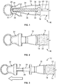
Fig. 1 is a cross-sectional view of a proximal portion of an embodiment of a catheter assembly according to an aspect of the present disclosure; -
Fig. 2 is a side elevational view of the proximal portion of the catheter assembly ofFig. 1 ; -
Fig. 3 is a side elevational view of the proximal portion of the catheter assembly ofFig. 1 , with a cap of the catheter assembly partially removed from a protective tip of the catheter assembly; -
Fig. 4 is a side elevational view of the proximal portion of the catheter assembly ofFig. 1 , with a cap of the catheter assembly fully removed from a protective tip of the catheter assembly; -
Fig. 5 is a side elevational view of the catheter assembly ofFig. 1 ; -
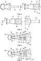
Fig. 6 is a cross-sectional view of a proximal portion of another embodiment of a catheter assembly according to an aspect of the present disclosure; -
Fig. 7 is a cross-sectional view of a proximal portion of yet another embodiment of a catheter assembly according to an aspect of the present disclosure; -
Fig. 8 is a cross-sectional view of a proximal portion of another embodiment of a catheter assembly according to an aspect of the present disclosure; -
Fig. 9 is a cross-sectional view of a proximal portion of yet another embodiment of a catheter assembly according to an aspect of the present disclosure; -
Fig. 10 is a side elevational view of a catheter assembly incorporating an alternative sleeve according to an aspect of the present disclosure; and -
Fig. 11 is a side elevational view of a catheter assembly incorporating another alternative sleeve according to an aspect of the present disclosure. -
Figs. 1 and 2 illustrate an embodiment of acatheter assembly 10, such as a urinary catheter assembly. Thecatheter assembly 10 may be variously configured without departing from the scope of the present disclosure, but in one embodiment, thecatheter assembly 10 includes a catheter 12 (such as a urinary catheter) at least partially positioned within asleeve 14, which may be defined by a flexible polymeric material (such as, but not limited to, polyurethane) wrapped about thecatheter 12. Aprotective tip 16 is secured or connected to aproximal end 18 of thesleeve 14, with an opposite ordistal end 20 of the sleeve 14 (Fig. 5 ) being sealed or otherwise closed to define a sealed container for thecatheter 16. - The
protective tip 16 extends between adistal end 22 and aproximal end 24. Theprotective tip 16 is sealingly connected or secured to thesleeve 14 at or adjacent to thedistal end 22 of theprotective tip 16. Theproximal end 24 of theprotective tip 16 may include an aperture or opening 26 that may be moved between a closed configuration (in which thecatheter 12 is fully positioned within thesleeve 14 andprotective tip 16 and there is no other object positioned within the opening 26) and an open configuration (in which thecatheter 12 or any other object is partially positioned within or extending through theopening 26, with a portion of the object positioned within theprotective tip 16 and another portion positioned outside of the protective tip 16). In one embodiment, theopening 26 is provided as a slit opening with one or more slits or cuts defining a plurality of deformable petals that may be moved to define the aforementioned open and closed configurations. In other embodiments, the opening may be differently configured, provided that it is configured to allow passage of the catheter therethrough. As will be described in greater detail below, theprotective tip 16 may include an internal proximal seal or sealing surface or sealingmember 28 and an internal distal seal or sealing surface or sealing member 30 (Fig. 1 ), with theseals proximal seal 28 positioned between the proximal anddistal ends protective tip 16. - The
catheter assembly 10 may further include acap 32 configured to be removably connected to theprotective tip 16. As shown inFig. 1 , thecap 32 may be connected to a proximal portion of theprotective tip 16 so as to form a substantially fluid- or water-tight seal, which encloses theopening 26 at theproximal end 24 of theprotective tip 16. In the illustrated embodiment, thecap 32 includes a projection or extension orplug 34, which is shown as being elongated along a central axis of thecap 32. While theprojection 34 is illustrated as having a solid, substantially cylindrical configuration with a substantially uniform outer diameter, it is also within the scope of the present disclosure for theprojection 34 to be differently configured (e.g., non-cylindrical). - When the
cap 32 has been mounted onto theprotective tip 16, theprojection 34 is at least partially positioned within theprotective tip 16, as shown inFig. 1 . Theprojection 34 extends through theproximal opening 26 of the protective tip 16 (with theprojection 34 holding theopening 26 in an at least partially open configuration) to sealingly cooperate with the protective tip 16 (or a component thereof) to provide the proximal anddistal seals projection 34 engages the protective tip 16 (or a component thereof) in at least three locations: at theproximal opening 26, at theproximal seal 28, and at thedistal seal 30. It may be preferred for theprojection 34 to have a relatively small outer diameter at the portion which is positioned within theproximal opening 26 of theprotective tip 16 in order to prevent tip deformation or shape-setting during storage of thecatheter assembly 10. - As noted above, the
projection 34 sealingly engages the proximal anddistal seals protective tip 16, thereby defining a fluid- or water-tight seal at each of theinternal seals seals projection 34, thereby forming a complete seal around an outer perimeter of theprojection 34. To form such a fluid- or water-tight seal, eachseal projection 34. For example, if theprojection 34 is substantially cylindrical (as in the illustrated embodiment), with a substantially circular cross-sectional shape, each of theinternal seals projection 34 is non-circular, one or both of theinternal seals projection 34. - It may be preferred for the openings or apertures defined by the
internal seals projection 34 which is positioned within the opening or aperture when thecap 32 has been mounted onto theprotective tip 16. Such a configuration may be preferred in order to promote a fluid- or water-tight seal at eachinternal seal internal seals projection 34. If one or both of theinternal seals projection 34, it may be advantageous for that seal or those seals to be formed of a deformable material to allow the seal to deform outwardly to accommodate the larger cross-section of theprojection 34. For example, in one embodiment, theinternal seals protective tip 16 may be formed of an elastomeric material (e.g., an O-ring), which provides a fluid-or water-tight seal while being deformable. In other embodiments, different materials such as silicone; the polyether block amide material marketed as PEBAX® by Arkema S.A. of Colombes, France; thermoplastic polyurethanes; thermoplastic elastomers; thermoplastic polyolefins; and the like may be used. It is also within the scope of the present disclosure for theproximal seal 28 to be formed of a different material than thedistal seal 30. - The proximal and distal
internal seals protective tip 16 or may be directly connected to the inner surface of theprotective tip 16 or may be connected to the inner surface of theprotective tip 16 via an intermediate member. For example, in the illustrated embodiment, the inner surface of theprotective tip 16 has a greater diameter at itsdistal end 22 than at itsproximal end 24. In such an embodiment, it may be advantageous for a grommet or spacer orintermediate member 36 to be connected to the inner surface of the protective tip 16 (Fig. 1 ), with thegrommet 36 defining an opening or aperture in which thedistal seal 30 may be formed. By providing agrommet 36, thedistal seal 30 may be positioned closer to the central axis of theprotective tip 16 without increasing the size of thedistal seal 30. Alternatively, thegrommet 36 itself (as a component of the protective tip 16) may provide an internal seal or sealing surface which sealingly engages theprojection 34. The material composition of thegrommet 36 may vary without departing from the scope of the present disclosure, but in one embodiment, thegrommet 36 is a generally annular member comprised of a generally rigid or semi-rigid material having a relatively low water permeability. For example, thegrommet 36 may be made from a thermoplastic elastomer, such as a non-swellable polyolefin material or PEBAX® or the like. - With the
cap 32 mounted upon theprotective tip 16, theprojection 34 forms fluid- or water-tight seals at eachinternal seal compartment 38 is defined between theinternal seals Fig. 1 ). An activating or hydrating fluid may be contained within thefluid reservoir 38, which fluid is configured to interact with a coating (such as, but not limited to, a hydrophilic coating) on thecatheter 12 to provide a lubricious surface to thecatheter 12. The nature of the activating fluid may vary depending on the nature of the coating on thecatheter 12 but, in one embodiment, the activating fluid is water. Thefluid reservoir 38 is at least partially filled with the activating fluid during manufacture (e.g., between 2 and 5 ml of activating fluid) and remains within thefluid reservoir 38 during storage and until thecatheter assembly 10 is used, as described below. Thefluid reservoir 38 may be filled with the activating fluid by any suitable method, but in one embodiment, the activating fluid may be dispensed into thefluid reservoir 38 while only one of theseals fluid reservoir 38, with the container being dissolved (in the case of a water-soluble container) or otherwise manipulated or processed to release the activating fluid into thefluid reservoir 38 after thefluid reservoir 38 has been sealed. Other methods of dispensing activating fluid into thefluid reservoir 38 may be employed without departing from the scope of the present disclosure. - As the
fluid reservoir 38 is intended to house the activating fluid during storage of thecatheter assembly 10, it may be preferred for the protective tip 16 (or at least the portion defining the fluid reservoir 38) to be formed of a rigid or semi-rigid material having a relatively low water permeability (e.g., polyethylene). Similarly, theprojection 34 of thecap 32 is intended to be at least partially positioned within thefluid reservoir 38 during storage of thecatheter assembly 10, so it may be advantageous for the cap 32 (or at least the projection 34) to be formed of a rigid or semi-rigid material having a relatively low water permeability. In one embodiment, thefluid reservoir 38 and theprojection 34 are formed of the same material, which may also be the same material as is used to form thegrommet 36, but in other embodiments, thefluid reservoir 38, theprojection 34, and thegrommet 36 may be formed of different materials. - In use, the
catheter assembly 10 is provided to a user in the configuration shown inFigs. 1 and 2 . In one embodiment, thecatheter assembly 10 may be enclosed within a sealed package or container (not illustrated) that must be opened by the user prior to use of thecatheter assembly 10. In other embodiments, thecap 32 andsleeve 14 serve as a sealed package for thecatheter 12. When thecatheter assembly 10 has been removed from the package (if provided), the user partially withdraws thecap 32 from the protective tip 16 (Fig. 3 ) so as to disengage theprojection 34 from the distalinternal seal 30. By so disengaging theprojection 34 from the distalinternal seal 30, the activating fluid is allowed to flow out of thefluid reservoir 38 and into thesleeve 14 via the opening or aperture defined by thedistal seal 30. It may be advantageous for thecatheter assembly 10 to be held vertically by the user, with thecap 32 andprotective tip 16 pointing upwardly, to promote flow of the activating fluid out of thefluid reservoir 38 and into thesleeve 14. By only partially removing thecap 32 from theprotective tip 16, theprojection 34 maintains the proximalinternal seal 28, thereby preventing the activating fluid from flowing out of theproximal opening 26 of theprotective tip 16. - Alternatively, rather than only partially removing the
cap 32 from theprotective tip 16, the user may completely remove thecap 32 from theprotective tip 16 to allow the activating fluid to flow from thefluid reservoir 38 into thesleeve 14. Although there is no proximalinternal seal 28 maintained by theprojection 34, theproximal opening 26 of the protective tip 16 (in a closed configuration) may provide a fluid- or water-tight seal to prevent the activating fluid from flowing out of thecatheter assembly 10. - The activating fluid contacts the hydrophilic coating of the
catheter 12 and interacts therewith to form a lubricious coating on thecatheter 12. Thesleeve 14 is preferably formed of a substantially transparent or translucent material to allow the user to visually confirm that the activating fluid has covered thecatheter 12 along the length of the coating. It may also be advantageous for thesleeve 14 to be formed of a flexible material to allow the user to manipulate thecatheter 12 through thesleeve 14 to better apply the activating fluid to the coating of thecatheter 12. In one embodiment, thesleeve 14 is formed of a soft, hydrophilic material, such as a polyurethane film, although other thin, soft film materials (either vapor permeable or impermeable) may also be used without departing from the scope of the present disclosure. - After the
catheter 12 has been treated with the activating fluid, thecap 32 may be fully removed from the protective tip 16 (if it has only been partially withdrawn from the protective tip 16), as inFig. 4 , which moves theproximal opening 26 to its closed configuration. Thereafter, the lubricatedcatheter 12 may be advanced proximally into and through theprotective tip 16 to exit theprotective tip 16 via theproximal opening 26. If thecatheter assembly 10 is provided as a urinary catheter assembly, the proximal end 24 (including the proximal opening 26) of theprotective tip 16 may be positioned within the urethra prior to advancing thecatheter 12 out of theproximal opening 26 of theprotective tip 16. With theproximal end 24 of theprotective tip 16 in the urethra, the proximal end of thecatheter 12 may be advanced out of theproximal opening 26 of theprotective tip 16 and through the urethra until the proximal end of thecatheter 12 reaches the bladder. Urine within the bladder flows into the open interior of thecatheter 12 via one or more eyes oropenings 40 of the catheter 12 (Fig. 1 ), where it then flows through thecatheter 12 and into thesleeve 14. More preferably, rather than allowing urine to flow into thesleeve 14, the distal end of thecatheter 12 may include a funnel or drainage device 42 (Fig. 5 ) that allows urine to drain out of thecatheter 12 and into a toilet or other waste receptacle. Thereafter, thecatheter 12 may be removed from the urethra, with thecatheter assembly 10 and urine being discarded after use. -
Fig. 6 illustrates an alternative embodiment of acatheter assembly 10a according to the present disclosure. The embodiment ofFig. 6 is similar to thecatheter assembly 10 ofFigs. 1-5 , with some differences in the configurations of theprotective tip 16a and thecap 32a. In the embodiment ofFig. 6 , theprotective tip 16a has a generally slimmer configuration than theprotective tip 16 ofFigs. 1-5 , with thedistal end 22a of theprotective tip 16a having a diameter that is larger than that of theproximal end 24a, but with the diameters being more similarly sized than in the embodiment ofFigs. 1-5 . As in the embodiment ofFigs. 1-5 , thedistal seal 30 is provided at a grommet orspacer 36a, with theproximal seal 28 being provided at an inner surface of theprotective tip 16a. However, it should be understood that the configurations of theinternal seals Figs. 1-5 . - As for the
cap 32a, it varies from thecap 32 ofFigs. 1-5 in that itsprojection 34a defines a hollow portion orcavity 44 at a distal portion of theprojection 34a. By such a configuration, a proximal end or portion of thecatheter 12 may be positioned within thehollow portion 44 of theprojection 34a during storage of thecatheter assembly 10a, prior to use. Such a configuration may be advantageous in that ashorter sleeve 14a may be employed, thereby decreasing the material cost of thecatheter assembly 10a and the storage space required. - It will be seen that the
catheter 12 has a smaller diameter than thedistal seal 30 in the embodiment ofFig. 6 , such that removing thecap 32a results in a gap or separation between thecatheter 12 and thedistal seal 30. This separation between thecatheter 12 and thedistal seal 30 allows activating fluid to flow out of theprotective tip 16a and into thesleeve 14a when thecap 32a (and, hence, theprojection 34a) has been removed, thereby hydrating the portion of thecatheter 12 positioned within thesleeve 14a. -
Fig. 7 illustrates a variation of the embodiment ofFig. 6 . Thecatheter assembly 10b ofFig. 7 is substantially identical to the embodiment ofFig. 6 , except that it is provided with an additional or third or auxiliary seal or flow-limitingfeature 46. In the illustrated embodiment, thethird seal 46 is positioned distally of thedistal seal 30, at or adjacent to thedistal end 22a of theprotective tip 16a (i.e., outside and distally of the fluid reservoir 38). Thethird seal 46 is configured to bear against thecatheter 12, thereby forming either a fluid- or water-tight seal therewith or providing a flow-limiting feature. Thethird seal 46, when providing a fluid- or water-tight seal, helps to maintain the activating fluid within thefluid reservoir 38 after thecap 32a is removed from theprotective tip 16a by preventing the activating fluid from flowing into thesleeve 14a. By such a configuration, the activating fluid remains within thefluid reservoir 38, such that the catheter 12 (and the coating thereof) comes into contact with the activating fluid as thecatheter 12 is advanced proximally through and out of theprotective tip 16a, rather than the activating fluid contacting the coating within thesleeve 14a. On the other hand, if thethird seal 46 is configured to provide a flow-limiting feature, at least a portion of thethird seal 46 may be spaced away or separated from the outer surface of thecatheter 12 to allow a regulated or limited flow of activating fluid into thesleeve 14a when thecap 32a is removed (as in the embodiment ofFig. 6 ). - The material composition of the
third seal 46 may vary without departing from the scope of the present disclosure, but in one embodiment, thethird seal 46 is formed of the same material as one or both of theother seals third seal 46 may be formed of a different material than theother seals third seal 46 include, but are not limited to, elastomeric materials, silicone, PEBAX®, thermoplastic polyurethanes, thermoplastic elastomers, thermoplastic polyolefins, and other non-woven fabric materials. -
Fig. 8 illustrates yet another embodiment of acatheter assembly 10c according to the present disclosure. Thecatheter assembly 10c ofFig. 8 is comparable to the embodiment ofFigs. 1-5 , except that it further includes a sponge orabsorbent member 48 associated with theprotective tip 16 to bear against thecatheter 12. In the illustrated embodiment, theabsorbent member 48 has a generally annular configuration and is associated with thegrommet 36, seated within a counterbore or pocket orcavity 50 at a distal side or end of the grommet 36 (i.e., outside and distally of the fluid reservoir 38). By such a configuration, theabsorbent member 48 absorbs and retains a portion of the activating fluid as it flows out of thefluid reservoir 38 and into thesleeve 14. As thecatheter 12 is advanced proximally through theprotective tip 16, it presses against theabsorbent member 48, with theabsorbent member 48 applying some of the retained activating fluid to the surface (and, hence, the hydrophilic coating) of thecatheter 12. This helps to ensure that activated fluid is applied to the entirety of the coated portion of thecatheter 12 as thecatheter 12 is advanced out of theprotective tip 16. The material composition of theabsorbent member 48 may vary without departing from the scope of the present disclosure but, in one embodiment, theabsorbent member 48 is formed of a sponge- or foam-like material, such as an open-cell sponge or foam material from foamed polymers (e.g., polyethylene or polyurethane or polyvinyl chloride) or the like. -
Fig. 9 illustrates an alternative seal configuration. In thecatheter assembly 10d ofFig. 9 , theprojection 34d of thecap 32d is spaced away from theprotective tip 16d at theproximal end 24d of theprotective tip 16d. A proximal fluid-tight seal is provided between theprotective tip 16d and thecap 32d by a fluid-tight film that is sealed to the two components, such as by heat seals. In one embodiment, one or both of the heat seals may be a peelable or breakable, as will be described in greater detail. In the embodiment ofFig. 9 , three fluid-tight films distal film 52c providing a distal seal, but it is within the scope of the present disclosure for thecatheter assembly 10d to include only one or two such films. For example, the fluid-tight film seal or seals may be configured to provide only a proximal seal, only a distal seal, or both a proximal seal and a distal seal for thefluid reservoir 38. - One of the illustrated
films 52a is provided within theprotective tip 16d, at or adjacent to theproximal end 24d of theprotective tip 16d. Thefilm 52a extends from the inner surface of theprotective tip 16d to the outer surface of thecap projection 34d, being connected (e.g., by heat seals) to each component. Another illustratedfilm 52b is positioned outside of theprotective tip 16d, at or adjacent to theproximal end 24d of theprotective tip 16d. Thesecond film 52b extends from the outer surface of theprotective tip 16d to the outer surface of thecap 32d (or a portion of theprojection 34d positioned outside of theprotective tip 16d) and is connected (e.g., by heat seals) to each component. The thirdillustrated film 52c is positioned within thesleeve 14 and is connected (e.g., by a heat seal) to thedistal end 22d of theprotective tip 16d and/or thegrommet 36a of theprotective tip 16d, overlaying the opening through which thecatheter 12 may be advanced into thefluid reservoir 38. Thethird film 52c may also be connected (e.g., by a heat seal) to the distal end of thecap projection 34d. - In use, the
cap 32d is moved proximally with respect to theprotective tip 16d, thereby removing any slack in thefilms proximal films projection 34d to separate from thedistal seal 30 while the proximal seals provided by thefilms film 52c is broken before the proximal seals are broken, such that the activating fluid flows out of the fluid reservoir 38 (though the opening formerly sealed by thedistal film 52c) and into thesleeve 14 to interact with the coating on thecatheter 12. In one embodiment, thedistal film 52c is connected to the distal end of thecap projection 34d and configured to break or detach from theprotective tip 16d orgrommet 36a upon sufficient proximal movement of thecap 32d. In another embodiment, thedistal film 52c may be configured to be broken by proximal movement of thecatheter 12 into contact with thefilm 52c. In yet another embodiment, thedistal film 52c may be configured to dissolve over time (e.g., if thefilm 52c is formed of a water-soluble material), which allows the activating fluid to be released into thesleeve 14 during storage of thecatheter assembly 10d for hydration of thecatheter 12 over an extended period of time. Alternatively, thedistal film 52c may be configured to only weaken over time, without dissolving, thereby preventing activating fluid from entering thesleeve 14, while also making it easier for a user to break the distal seal. - Depending on the nature of the
proximal films catheter assembly 10d. Breaking/peeling the heat seals of thefilms cap 32d to be fully removed and separated from theprotective tip 16d. In one embodiment, thefilm 52a positioned within theprotective tip 16d may be configured to dissolve or weaken over time (e.g., if thefilm 52a is formed of a water-soluble material), which makes it easier for a user to break the seal and remove thecap 32d immediately prior to use. -
Figs. 10 and 11 illustratecatheter assemblies sleeves 14e and 14f. The illustratedsleeves 14e and 14f are configured to slow the rate at which activating fluid flows through the sleeve and to extend the time that the activating fluid is in contact with all coated areas of thecatheter 12. Either of thesleeves 14e and 14f may be used in combination with any of the catheter assemblies described herein or with other catheter assemblies in which an activating fluid flows through a catheter-containing sleeve. - In the embodiment of
Fig. 10 , thesleeve 14e is provided with a plurality ofconstrictions 54, but may have as few as oneconstriction 54. Theconstrictions 54 effectively decrease the size of the gap between thesleeve 14e and thecatheter 12, thereby preventing the activating fluid from quickly flowing through thesleeve 14e. As the activating fluid flows through thesleeve 14e, it is funneled through the relatively small opening defined by eachconstriction 54, which causes the activating fluid to remain upstream of eachconstriction 54 for a longer amount of time, in contact with the coating on thecatheter 12. The exact flow rate of the activating fluid through thesleeve 14e and through the opening defined by eachconstriction 54 may be varied by adjusting the configuration of each constriction 54 (e.g., by increasing or decreasing the size of the opening defined by a constriction 54). Theconstrictions 54 may be formed by any suitable method, but in one embodiment are formed by a heat sealing procedure that seals together opposing faces of thesleeve 14e. - In the embodiment of
Fig. 11 , the sleeve 14f is provided with a plurality ofabsorbent inserts 56, but may have as few as oneabsorbent insert 56. The absorbent inserts 54 absorb a portion of the activating fluid as it flows through the sleeve 14f. As thecatheter 12 is advanced proximally out of the sleeve 14f, it brushes against the absorbent inserts 54, which transfer activating fluid to the coating of the catheter 12 (similar to the action of theabsorbent member 48 ofFig. 8 ). The sleeve 14f may be squeezed at the absorbent inserts 56 to transfer additional amounts of activating fluid from the absorbent inserts 56 to thecatheter 12. The configuration of the absorbent inserts 56 may vary, but it may be advantageous for them to be substantially annular and formed from a sponge- or foam-like non-woven fabric material, such as an open-cell sponge or foam material from foamed polymers (e.g., polyethylene or polyurethane or polyvinyl chloride) or the like. The absorbent inserts 56 may be sealed or secured to the sleeve 14f by any suitable means, which may vary according to the material composition of the absorbent inserts 56 and the sleeve 14f. - It should be understood that the methods described herein are merely exemplary, and that the steps described above may be carried out in a different order. Further, other steps may be included when using the devices described herein. Additionally, one or more of the steps described herein in connection with the methods may be omitted or modified without departing from the scope of the present disclosure. Similarly, the systems described herein are merely exemplary, and they may be differently configured (e.g., by combining one or more components of one described embodiment with one or more components of another described embodiment) without departing from the scope of the present disclosure.
- Examples of the present subject matter described above may be beneficial alone or in combination with one or more other aspects. Without limiting the foregoing description, in accordance with one example of the subject matter herein, there is provided a catheter assembly, which includes a sleeve with a catheter at least partially positioned therein. There is a coating on at least a part of the catheter which produces a low-friction surface on the catheter when treated with an activating fluid. A protective tip is connected to the sleeve and has proximal and distal internal seals, with the proximal seal being positioned at a proximal end of the protective tip or between proximal and distal ends of the protective tip. A cap includes a projection removably received within the protective tip for sealing engagement with the proximal and distal seals to define a fluid reservoir within the protective tip, with an activating fluid contained within the fluid reservoir.
- In accordance with another example which may be used or combined with the first example, the projection has a substantially uniform outer diameter.
- In accordance with another example which may be used or combined with the any of the preceding examples, at least one of the internal seals is formed of a deformable material.
- In accordance with another example which may be used or combined with the any of the preceding examples, a grommet is secured to an inner surface of the protective tip, with the grommet defining an opening in which the distal internal seal is positioned.
- In accordance with another example which may be used or combined with the fourth example, a distal side of the grommet defines a pocket, with a generally annular absorbent member at least partially positioned within the pocket.
- In accordance with another example which may be used or combined with any of the preceding examples, a distal portion of the projection defines a cavity in which a proximal end of the catheter is positionable.
- In accordance with another example which may be used or combined with the preceding example, a third internal seal is positioned distally of the distal internal seal, with the third internal seal being configured to bear against the catheter.
- In accordance with another example which may be used or combined with the sixth example, a third internal seal is positioned distally of the distal internal seal, with at least a portion of the third internal seal being separated from the catheter to provide a flow-limiting arrangement.
- In accordance with another example, there is provided a catheter assembly, which includes a sleeve with a catheter at least partially positioned therein. There is a coating on at least a part of the catheter which produces a low-friction surface on the catheter when treated with an activating fluid. A protective tip is connected to the sleeve and defines a fluid reservoir, which contains an activating fluid. A cap includes a projection removably received within the protective tip. At least one fluid-tight film seal is positioned outside of the protective tip and extends between an outer surface of the protective tip and an outer surface of the cap or projection, within the fluid reservoir and extends between an internal surface of the protective tip and an outer surface of the projection, or within the sleeve and connected to a distal end of the protective tip.
- In accordance with another example which may be used or combined with the preceding example, the fluid-tight film seal is peelable or breakable.
- In accordance with another example which may be used or combined with any of the preceding two examples, 1 the fluid-tight film seal is positioned outside of the protective tip and extends between the outer surface of the protective tip and the outer surface of the cap or projection. A second fluid-tight film seal is positioned within the fluid reservoir and extends between the internal surface of the protective tip and the outer surface of the projection.
- In accordance with another example which may be used or combined with any of the ninth through tenth examples, the fluid-tight film seal is positioned outside of the protective tip and extends between the outer surface of the protective tip and the outer surface of the cap or projection. A second fluid-tight film seal is positioned within the sleeve and is connected to the distal end of the protective tip.
- In accordance with another example which may be used or combined with any of the ninth through tenth aspects, the fluid-tight film seal is positioned within the fluid reservoir and extends between the internal surface of the protective tip and the outer surface of the projection. A second fluid-tight film seal is positioned within the sleeve and is connected to the distal end of the protective tip.
- In accordance with another example which may be used or combined with any of the ninth through tenth examples, the fluid-tight film seal is positioned outside of the protective tip and extends between the outer surface of the protective tip and the outer surface of the cap or projection. A second fluid-tight film seal is positioned within the fluid reservoir and extends between the internal surface of the protective tip and the outer surface of the projection. A third fluid-tight film seal is positioned within the sleeve and is connected to the distal end of the protective tip.
- In accordance with another example which may be used or combined with any of the ninth through tenth examples, the fluid-tight film seal is positioned within the sleeve, connected to a distal end of the protective tip, and formed of a water-soluble material.
- In accordance with another example which may be used or combined with any of the preceding examples, the sleeve includes a constriction configured to reduce the space between the sleeve and the catheter.
- In accordance with another example which may be used or combined with the preceding example, the sleeve has opposing faces, with the constriction being defined by a heat seal between the opposing faces of the sleeve.
- In accordance with another example which may be used or combined with any of the preceding two examples, the sleeve includes a second constriction configured to reduce the space between the sleeve and the catheter.
- In accordance with another example which may be used or combined with any of the first through fifteenth examples, an absorbent insert is positioned within the sleeve.
- In accordance with another example which may be used or combined with the preceding example, a second absorbent insert is positioned within the sleeve.
Claims (15)
- A catheter assembly (10, 10a, 10b, 10c, 10d, 10e, 10f), comprising:a sleeve (14, 14a, 14e, 14f);a catheter (12) at least partially positioned within the sleeve (14, 14a, 14e, 14f) and having a coating on at least a part of its length which produces a low-friction surface on the catheter (12) when treated with an activating fluid;a protective tip (16, 16a, 16d) having proximal and distal internal seals (28, 30, 52a, 52c) is sealingly connected to the sleeve (14, 14a, 14e, 14f) at or adjacent to the distal end (22) of the protective tip (16), with the proximal seal (28, 52a) positioned at a proximal end (24, 24a, 24d) of the protective tip (16, 16a, 16d) or between proximal and distal ends (22, 22a, 22d, 24, 24a, 24d) of the protective tip(16, 16a, 16d);a cap (32, 32a, 32d) including a projection (34, 34a, 34d) removably received within the protective tip (16, 16a, 16d) for sealing engagement with the proximal and distal seals (28, 30, 52a, 52c) to define a fluid reservoir (38) within the protective tip (16, 16a, 16d); andan activating fluid contained within the fluid reservoir (16, 16a, 16d).
- The catheter assembly (10, 10a, 10b, 10c, 10d, 10e, 10f) of claim 1, wherein the projection (34, 34a, 34d) has a substantially uniform outer diameter.
- The catheter assembly (10, 10a, 10b, 10c, 10d, 10e, 10f) of any of the preceding claims, wherein at least one of the internal seals (28, 30, 52a, 52c) is formed of a deformable material.
- The catheter assembly (10, 10a, 10b, 10c, 10d, 10e, 10f) of any of the preceding claims, further comprising a grommet (36, 36a) secured to an inner surface of the protective tip (16, 16a, 16d), wherein the grommet (36, 36a) defines an opening in which the distal internal seal (30) is positioned.
- The catheter assembly (10c) of claim 4, wherein a distal side of the grommet (36) defines a pocket (50), and a generally annular absorbent member (48) is at least partially positioned within the pocket (50).
- The catheter assembly (10a, 10b) of any of the preceding claims, wherein a distal portion of the projection (34a) defines a cavity (44) in which a proximal end of the catheter (12) is positionable.
- The catheter assembly (10) of claim 6, further comprising a third internal seal (46) positioned distally of the distal internal seal (30), wherein the third internal seal (46) is configured to bear against the catheter (12).
- The catheter assembly (10b) of claim 6, further comprising a third internal seal (46) positioned distally of the distal internal seal (30), wherein at least a portion of the third internal seal (46) is separated from the catheter (12) to provide a flow-limiting arrangement.
- The catheter assembly (10d) of claim 1, wherein at least one of the internal seals (52a, 52c) comprising:a fluid-tight film seal (52a, 52c) positioned within the fluid reservoir (38) and extending between an internal surface of the protective tip (16d) and an outer surface of the projection 34d); orpositioned within the sleeve (14) and connected to a distal end of the protective tip (16d) andwherein the fluid-tight film seal (52a, 52c) is preferably pealable or breakable.
- The catheter assembly (10d) of claim 9, further comprising an external fluid- tight film seal (52b) positioned outside of the protective tip (16d) and extending between an outer surface of the protective tip (16d) and an outer surface of the cap (32d) or the outer surface of the projection (34d).
- The catheter assembly (10d) of any of claims 9-10, wherein the fluid- tight film seal (52c) is positioned within the sleeve (14), connected to a distal end of the protective tip (16d), and formed of a water-soluble material.
- The catheter assembly (10e) of any of the preceding claims, wherein the sleeve (14e) includes a constriction (54) and preferably a second constriction (54) configured to reduce the space between the sleeve (14e) and the catheter (12), the constriction (54) being preferably defined by a heat seal between opposing faces of the sleeve (14e).
- The catheter assembly (10e) of claim 12, wherein the sleeve (14e) comprises opposing faces, and the constriction (54) is defined by a heat seal between the opposing faces of the sleeve (14e).
- The catheter assembly (10f) of any of claims 1 -11, further comprising an absorbent insert (56) positioned within the sleeve (14f).
- The catheter assembly (10f) of claim 14, further comprising a second absorbent insert (56) positioned within the sleeve (14f).
Applications Claiming Priority (2)
| Application Number | Priority Date | Filing Date | Title |
|---|---|---|---|
| US201361911535P | 2013-12-04 | 2013-12-04 | |
| PCT/US2014/068299 WO2015084923A1 (en) | 2013-12-04 | 2014-12-03 | Urinary catheter protective tips having a fluid reservoir |
Publications (2)
| Publication Number | Publication Date |
|---|---|
| EP3077031A1 EP3077031A1 (en) | 2016-10-12 |
| EP3077031B1 true EP3077031B1 (en) | 2020-11-25 |
Family
ID=52134428
Family Applications (1)
| Application Number | Title | Priority Date | Filing Date |
|---|---|---|---|
| EP14816051.8A Active EP3077031B1 (en) | 2013-12-04 | 2014-12-03 | Urinary catheter protective tips having a fluid reservoir |
Country Status (9)
| Country | Link |
|---|---|
| US (3) | US10946172B2 (en) |
| EP (1) | EP3077031B1 (en) |
| AU (1) | AU2014360561B2 (en) |
| CA (1) | CA2923674C (en) |
| DK (1) | DK3077031T3 (en) |
| ES (1) | ES2841177T3 (en) |
| HU (1) | HUE053380T2 (en) |
| LT (1) | LT3077031T (en) |
| WO (1) | WO2015084923A1 (en) |
Families Citing this family (15)
| Publication number | Priority date | Publication date | Assignee | Title |
|---|---|---|---|---|
| WO2016204858A1 (en) * | 2015-06-15 | 2016-12-22 | Hollister Incorporated | Urinary catheters having limited reusability |
| AU2018301401B2 (en) * | 2017-07-12 | 2022-06-09 | Hollister Incorporated | Ready-to-use urinary catheter assembly |
| GB201721955D0 (en) * | 2017-12-27 | 2018-02-07 | Convatec Ltd | Catheter wetting devices |
| CA3100541A1 (en) | 2018-05-17 | 2019-11-21 | Hollister Incorporated | Methods of making sleeved hydrophilic catheter assemblies |
| WO2019245679A1 (en) * | 2018-06-19 | 2019-12-26 | Hollister Incorporated | Female urinary catheter deployment devices and methods of using the same |
| EP3883620A1 (en) * | 2018-11-21 | 2021-09-29 | Hollister Incorporated | Hydration solutions containing volatile solutes and medical device products including the same |
| US20210299410A1 (en) * | 2020-03-27 | 2021-09-30 | Wiesconcepts, LLC | Protective Sheath Assembly For A Method Of Evaluation And/Or Retrieving Pathological Samples From A Body Orifice, A Method For Administering An Anesthetic, Formulated Medication And/Or Chemotherapy Using A Protective Sheath Assembly |
| EP4138972B1 (en) * | 2020-04-24 | 2023-11-22 | ConvaTec Limited | A wetting mechanism for a catheter |
| GB202006055D0 (en) * | 2020-04-24 | 2020-06-10 | Convatec Ltd | A wetting mechanism for a catheter |
| GB202006056D0 (en) * | 2020-04-24 | 2020-06-10 | Convatec Ltd | A catheter |
| GB202006060D0 (en) * | 2020-04-24 | 2020-06-10 | Convatec Ltd | A wetting mechanism for a catheter |
| GB202006059D0 (en) * | 2020-04-24 | 2020-06-10 | Convatec Ltd | A wetting mechanism for a catheter |
| GB202105822D0 (en) | 2021-04-23 | 2021-06-09 | Convatec Ltd | Intermittent catheter |
| WO2023180725A1 (en) * | 2022-03-21 | 2023-09-28 | Convatec Limited | A catheter assembly |
| WO2023180718A1 (en) * | 2022-03-21 | 2023-09-28 | Convatec Limited | A catheter assembly |
Citations (14)
| Publication number | Priority date | Publication date | Assignee | Title |
|---|---|---|---|---|
| US2849739A (en) | 1952-11-04 | 1958-09-02 | A H Wirz Inc | Sealing nitrocellulose cement |
| US4925448A (en) | 1988-03-30 | 1990-05-15 | The Cleveland Clinic Foundation | Catheter package |
| US5454798A (en) | 1993-05-14 | 1995-10-03 | Mentor Corporation | Disposable urine bag |
| US6053905A (en) | 1998-02-23 | 2000-04-25 | Tyco International (Us) Inc. | Self contained urethral catheter assembly with lubricating chamber |
| US6090075A (en) | 1998-03-31 | 2000-07-18 | House; Jamie Glen | Disposable urinary catheterization assembly |
| US20010001443A1 (en) | 1996-09-18 | 2001-05-24 | Coloplast A/S | Ready-to-use urinary catheter assembly |
| US20030018302A1 (en) | 2001-07-19 | 2003-01-23 | Kavanagh Seamus T. | Lubricating and gripping device for urinary catheter package |
| US20070106205A1 (en) | 2002-02-11 | 2007-05-10 | Baxter International Inc. | Dialysis connector and cap having an integral disinfectant |
| US20090032536A1 (en) | 2007-08-03 | 2009-02-05 | Hobbs Sr Terry J | Cap for caulking cartridge or similar container |
| US7922712B2 (en) | 2001-09-24 | 2011-04-12 | Coloplast A/S | Urinary catheter assembly allowing for non-contaminated insertion of the catheter into a urinary canal |
| WO2011094690A1 (en) | 2010-01-29 | 2011-08-04 | The Procter & Gamble Company | Improved water-soluble film having blend of pvoh polymers, and packets made therefrom |
| US20110230864A1 (en) * | 2010-03-16 | 2011-09-22 | Adapta Medical, Inc. | Catheter Reservoir Seals |
| US20130079755A1 (en) | 2011-09-23 | 2013-03-28 | Adapta Medical, Inc. | Catheter Advancement |
| US20130079756A1 (en) | 2011-09-23 | 2013-03-28 | Adapta Medical, Inc. | Catheter Reservoir Seal |
Family Cites Families (38)
| Publication number | Priority date | Publication date | Assignee | Title |
|---|---|---|---|---|
| US1137086A (en) * | 1913-02-13 | 1915-04-27 | William Rodiger | Collapsible tube. |
| US3187966A (en) * | 1963-07-09 | 1965-06-08 | Continental Can Co | Flexible container with snip-off and reseal features |
| US3421509A (en) * | 1965-12-17 | 1969-01-14 | John M Fiore | Urethral catheter |
| US3640418A (en) * | 1970-04-06 | 1972-02-08 | Dover Molded Products Co | Throwaway closure for test tube |
| US3861395A (en) | 1973-09-25 | 1975-01-21 | Tokuso Taniguchi | Automated catheter |
| US3968876A (en) * | 1975-03-19 | 1976-07-13 | Brookfield Richard A | Sealed container with a sterilized hypodermic needle within it and method for effecting the sealing thereof |
| US4137916A (en) * | 1976-11-22 | 1979-02-06 | Travenol Laboratories, Inc. | Catheter plug assembly |
| US4834711A (en) * | 1987-08-14 | 1989-05-30 | Greenfield Albert R | Dispensing appliance for insertion and maintenance of catheters, tubes and other articles of therapy |
| US5154327A (en) * | 1990-04-05 | 1992-10-13 | Long Kyle D | Sealable nozzle adaptor for use with a caulking tube cartridge |
| US5217114A (en) * | 1991-05-15 | 1993-06-08 | Applied Vascular Devices, Inc. | Catheter package |
| US5209726A (en) | 1992-05-04 | 1993-05-11 | Goosen Carl C | Self-lubricating urethral catheter and method for self-catheterization |
| SE9600276D0 (en) | 1996-01-25 | 1996-01-25 | Astra Ab | A wetting device for wetting a hydrophilic catheter and a urine collection bag incorporating said device |
| US6004305A (en) * | 1996-05-03 | 1999-12-21 | Spectrum Medsystems, Inc. | Drainage catheter assembly |
| GB9624269D0 (en) | 1996-11-21 | 1997-01-08 | Rusch Manufacturing Uk Limited | Packaged medical device |
| US5792114A (en) * | 1996-12-16 | 1998-08-11 | Fiore; John M. | Introducer for sterile insertion of catheter |
| SE9904635D0 (en) | 1999-12-17 | 1999-12-17 | Astra Ab | Catheter wetting apparatus |
| US6375051B1 (en) * | 2000-10-16 | 2002-04-23 | Richard A. Iverson | Caulk storage and dispensing system with a reusable closure device |
| US6387073B1 (en) * | 2000-12-06 | 2002-05-14 | Weiler Engineering, Inc. | Hermetically sealed container with medicament storing and dispensing insert |
| US6578709B1 (en) * | 2001-07-19 | 2003-06-17 | Hollister Incorporated | Urinary catheter package and lubricator therefor with combined gripping and sealing means |
| AU2002347446A1 (en) * | 2002-11-13 | 2004-06-03 | Hoffmann Neopac Ag | Tamper evident tube closure with twist-away centring |
| DE10329126B4 (en) | 2003-06-27 | 2006-11-09 | Willy Rüsch GmbH | Catheter application system |
| US7188750B2 (en) * | 2003-09-05 | 2007-03-13 | Hospira, Inc. | Blow fill sealed container with twist off top operated by overcap and method of forming the same |
| US20050109648A1 (en) | 2003-10-30 | 2005-05-26 | Hollister Incorporated | No-touch packaging configurations and application methods for hydrophilic intermittent catheters |
| US7410481B1 (en) * | 2004-04-06 | 2008-08-12 | Mitts Cheryl A | Urethral catheter device and method of using |
| US7596927B2 (en) * | 2004-05-21 | 2009-10-06 | Moser Jerry W | Method of tamper proofing a container assembly with an easily opened tamper evident shrink band |
| WO2006121508A2 (en) | 2005-05-06 | 2006-11-16 | Hollister Incorporated | Two-piece lubricant housing for urinary catheter packages |
| US8177774B2 (en) | 2005-08-17 | 2012-05-15 | Adapta Medical, Inc. | Catheterization assembly |
| US7601158B2 (en) | 2006-07-17 | 2009-10-13 | Colorado Catheter Company, Inc. | Devices for handling catheter assembly |
| FR2914193B1 (en) | 2007-03-27 | 2009-06-05 | Braun Medical Sas | CONDITIONED INTRALUMINAL PROBE READY TO USE |
| EP2224988A2 (en) | 2007-11-29 | 2010-09-08 | Coloplast A/S | An assembly for wetting a medical device |
| US20110120892A1 (en) | 2008-07-18 | 2011-05-26 | Coloplast A/S | Blocking device |
| WO2011019359A1 (en) | 2009-08-13 | 2011-02-17 | C. R. Bard, Inc. | Catheter having internal hydrating fluid storage and/or catheter package using the same and method of making and/or using the same |
| EP2450076B1 (en) * | 2010-11-04 | 2017-10-25 | Curan Medical B.V. | Package with catheter |
| EP2545952B1 (en) * | 2011-07-15 | 2014-04-02 | Dentsply IH AB | Medical device assembly |
| AR082385A1 (en) * | 2011-07-25 | 2012-12-05 | Lavaque Oscar | A BOTTLE NECK CAPSULE CONFORMED BY AN ADHESIVE DISK AND A THERM-CONTRAIBLE HOSE, A PROCEDURE FOR THE ONLINE INCLUSION OF SUCH CAPSULE, AND A MACHINE TO CONFORM SUCH CAPSULE THROUGH SAID PROCEDURE |
| US9682220B2 (en) * | 2011-08-29 | 2017-06-20 | Coloplast A/S | Assembly for urinary drainage |
| CN103974739B (en) * | 2011-12-09 | 2017-04-05 | 科洛普拉斯特公司 | Liquid-stopping device |
| US9327095B2 (en) * | 2013-03-11 | 2016-05-03 | Becton, Dickinson And Company | Blood control catheter with antimicrobial needle lube |
-
2014
- 2014-12-03 EP EP14816051.8A patent/EP3077031B1/en active Active
- 2014-12-03 US US14/914,822 patent/US10946172B2/en active Active
- 2014-12-03 HU HUE14816051A patent/HUE053380T2/en unknown
- 2014-12-03 LT LTEP14816051.8T patent/LT3077031T/en unknown
- 2014-12-03 WO PCT/US2014/068299 patent/WO2015084923A1/en active Application Filing
- 2014-12-03 ES ES14816051T patent/ES2841177T3/en active Active
- 2014-12-03 CA CA2923674A patent/CA2923674C/en active Active
- 2014-12-03 AU AU2014360561A patent/AU2014360561B2/en active Active
- 2014-12-03 DK DK14816051.8T patent/DK3077031T3/en active
-
2021
- 2021-01-20 US US17/153,184 patent/US11813412B2/en active Active
-
2023
- 2023-10-10 US US18/484,006 patent/US20240033478A1/en active Pending
Patent Citations (14)
| Publication number | Priority date | Publication date | Assignee | Title |
|---|---|---|---|---|
| US2849739A (en) | 1952-11-04 | 1958-09-02 | A H Wirz Inc | Sealing nitrocellulose cement |
| US4925448A (en) | 1988-03-30 | 1990-05-15 | The Cleveland Clinic Foundation | Catheter package |
| US5454798A (en) | 1993-05-14 | 1995-10-03 | Mentor Corporation | Disposable urine bag |
| US20010001443A1 (en) | 1996-09-18 | 2001-05-24 | Coloplast A/S | Ready-to-use urinary catheter assembly |
| US6053905A (en) | 1998-02-23 | 2000-04-25 | Tyco International (Us) Inc. | Self contained urethral catheter assembly with lubricating chamber |
| US6090075A (en) | 1998-03-31 | 2000-07-18 | House; Jamie Glen | Disposable urinary catheterization assembly |
| US20030018302A1 (en) | 2001-07-19 | 2003-01-23 | Kavanagh Seamus T. | Lubricating and gripping device for urinary catheter package |
| US7922712B2 (en) | 2001-09-24 | 2011-04-12 | Coloplast A/S | Urinary catheter assembly allowing for non-contaminated insertion of the catheter into a urinary canal |
| US20070106205A1 (en) | 2002-02-11 | 2007-05-10 | Baxter International Inc. | Dialysis connector and cap having an integral disinfectant |
| US20090032536A1 (en) | 2007-08-03 | 2009-02-05 | Hobbs Sr Terry J | Cap for caulking cartridge or similar container |
| WO2011094690A1 (en) | 2010-01-29 | 2011-08-04 | The Procter & Gamble Company | Improved water-soluble film having blend of pvoh polymers, and packets made therefrom |
| US20110230864A1 (en) * | 2010-03-16 | 2011-09-22 | Adapta Medical, Inc. | Catheter Reservoir Seals |
| US20130079755A1 (en) | 2011-09-23 | 2013-03-28 | Adapta Medical, Inc. | Catheter Advancement |
| US20130079756A1 (en) | 2011-09-23 | 2013-03-28 | Adapta Medical, Inc. | Catheter Reservoir Seal |
Non-Patent Citations (1)
| Title |
|---|
| "Case number T 1705/17 - 3.2.06 -EP 11729430.6", BOARDS OF APPEAL OF THE EUROPEAN PATENT OFFICE, 21 August 1505 (1505-08-21) |
Also Published As
| Publication number | Publication date |
|---|---|
| US11813412B2 (en) | 2023-11-14 |
| ES2841177T3 (en) | 2021-07-07 |
| US10946172B2 (en) | 2021-03-16 |
| US20240033478A1 (en) | 2024-02-01 |
| US20210138188A1 (en) | 2021-05-13 |
| AU2014360561A1 (en) | 2016-03-17 |
| WO2015084923A1 (en) | 2015-06-11 |
| AU2014360561B2 (en) | 2018-10-25 |
| CA2923674A1 (en) | 2015-06-11 |
| DK3077031T3 (en) | 2021-01-11 |
| CA2923674C (en) | 2021-06-08 |
| HUE053380T2 (en) | 2021-06-28 |
| LT3077031T (en) | 2021-01-11 |
| EP3077031A1 (en) | 2016-10-12 |
| US20160213880A1 (en) | 2016-07-28 |
Similar Documents
| Publication | Publication Date | Title |
|---|---|---|
| US11813412B2 (en) | Urinary catheter protective tips having a fluid reservoir | |
| EP3651844B1 (en) | Ready-to-use urinary catheter assembly | |
| US10406322B2 (en) | Catheter assemblies having a protective lubricious sleeve | |
| CA2941263C (en) | Intermittent catheters having hydration/gripper devices | |
| EP1858575B1 (en) | A package for a medical device | |
| EP3478353B1 (en) | Urinary catheter with sealed chamber | |
| EP4138970B1 (en) | A wetting mechanism for a catheter | |
| EP4138972B1 (en) | A wetting mechanism for a catheter |
Legal Events
| Date | Code | Title | Description |
|---|---|---|---|
| PUAI | Public reference made under article 153(3) epc to a published international application that has entered the european phase |
Free format text: ORIGINAL CODE: 0009012 |
|
| 17P | Request for examination filed |
Effective date: 20160616 |
|
| AK | Designated contracting states |
Kind code of ref document: A1 Designated state(s): AL AT BE BG CH CY CZ DE DK EE ES FI FR GB GR HR HU IE IS IT LI LT LU LV MC MK MT NL NO PL PT RO RS SE SI SK SM TR |
|
| AX | Request for extension of the european patent |
Extension state: BA ME |
|
| RIN1 | Information on inventor provided before grant (corrected) |
Inventor name: O'FLYNN, PADRAIG, M. Inventor name: JAMES J. FITZPATRICK Inventor name: ROSTAMI, SHAMSEDIN |
|
| DAX | Request for extension of the european patent (deleted) | ||
| STAA | Information on the status of an ep patent application or granted ep patent |
Free format text: STATUS: EXAMINATION IS IN PROGRESS |
|
| 17Q | First examination report despatched |
Effective date: 20190709 |
|
| REG | Reference to a national code |
Ref country code: DE Ref legal event code: R079 Ref document number: 602014072741 Country of ref document: DE Free format text: PREVIOUS MAIN CLASS: A61M0025000000 Ipc: A61M0027000000 |
|
| GRAP | Despatch of communication of intention to grant a patent |
Free format text: ORIGINAL CODE: EPIDOSNIGR1 |
|
| STAA | Information on the status of an ep patent application or granted ep patent |
Free format text: STATUS: GRANT OF PATENT IS INTENDED |
|
| RIC1 | Information provided on ipc code assigned before grant |
Ipc: A61M 25/00 20060101ALI20200821BHEP Ipc: A61M 27/00 20060101AFI20200821BHEP Ipc: A61M 25/01 20060101ALI20200821BHEP |
|
| INTG | Intention to grant announced |
Effective date: 20200908 |
|
| GRAS | Grant fee paid |
Free format text: ORIGINAL CODE: EPIDOSNIGR3 |
|
| GRAA | (expected) grant |
Free format text: ORIGINAL CODE: 0009210 |
|
| STAA | Information on the status of an ep patent application or granted ep patent |
Free format text: STATUS: THE PATENT HAS BEEN GRANTED |
|
| AK | Designated contracting states |
Kind code of ref document: B1 Designated state(s): AL AT BE BG CH CY CZ DE DK EE ES FI FR GB GR HR HU IE IS IT LI LT LU LV MC MK MT NL NO PL PT RO RS SE SI SK SM TR |
|
| REG | Reference to a national code |
Ref country code: GB Ref legal event code: FG4D |
|
| REG | Reference to a national code |
Ref country code: CH Ref legal event code: EP |
|
| REG | Reference to a national code |
Ref country code: AT Ref legal event code: REF Ref document number: 1337587 Country of ref document: AT Kind code of ref document: T Effective date: 20201215 |
|
| REG | Reference to a national code |
Ref country code: DE Ref legal event code: R096 Ref document number: 602014072741 Country of ref document: DE |
|
| REG | Reference to a national code |
Ref country code: IE Ref legal event code: FG4D |
|
| REG | Reference to a national code |
Ref country code: DK Ref legal event code: T3 Effective date: 20210108 |
|
| REG | Reference to a national code |
Ref country code: NL Ref legal event code: FP |
|
| REG | Reference to a national code |
Ref country code: SE Ref legal event code: TRGR |
|
| REG | Reference to a national code |
Ref country code: AT Ref legal event code: MK05 Ref document number: 1337587 Country of ref document: AT Kind code of ref document: T Effective date: 20201125 |
|
| PG25 | Lapsed in a contracting state [announced via postgrant information from national office to epo] |
Ref country code: PT Free format text: LAPSE BECAUSE OF FAILURE TO SUBMIT A TRANSLATION OF THE DESCRIPTION OR TO PAY THE FEE WITHIN THE PRESCRIBED TIME-LIMIT Effective date: 20210325 Ref country code: NO Free format text: LAPSE BECAUSE OF FAILURE TO SUBMIT A TRANSLATION OF THE DESCRIPTION OR TO PAY THE FEE WITHIN THE PRESCRIBED TIME-LIMIT Effective date: 20210225 Ref country code: RS Free format text: LAPSE BECAUSE OF FAILURE TO SUBMIT A TRANSLATION OF THE DESCRIPTION OR TO PAY THE FEE WITHIN THE PRESCRIBED TIME-LIMIT Effective date: 20201125 Ref country code: FI Free format text: LAPSE BECAUSE OF FAILURE TO SUBMIT A TRANSLATION OF THE DESCRIPTION OR TO PAY THE FEE WITHIN THE PRESCRIBED TIME-LIMIT Effective date: 20201125 Ref country code: GR Free format text: LAPSE BECAUSE OF FAILURE TO SUBMIT A TRANSLATION OF THE DESCRIPTION OR TO PAY THE FEE WITHIN THE PRESCRIBED TIME-LIMIT Effective date: 20210226 |
|
| PG25 | Lapsed in a contracting state [announced via postgrant information from national office to epo] |
Ref country code: LV Free format text: LAPSE BECAUSE OF FAILURE TO SUBMIT A TRANSLATION OF THE DESCRIPTION OR TO PAY THE FEE WITHIN THE PRESCRIBED TIME-LIMIT Effective date: 20201125 Ref country code: PL Free format text: LAPSE BECAUSE OF FAILURE TO SUBMIT A TRANSLATION OF THE DESCRIPTION OR TO PAY THE FEE WITHIN THE PRESCRIBED TIME-LIMIT Effective date: 20201125 Ref country code: IS Free format text: LAPSE BECAUSE OF FAILURE TO SUBMIT A TRANSLATION OF THE DESCRIPTION OR TO PAY THE FEE WITHIN THE PRESCRIBED TIME-LIMIT Effective date: 20210325 Ref country code: BG Free format text: LAPSE BECAUSE OF FAILURE TO SUBMIT A TRANSLATION OF THE DESCRIPTION OR TO PAY THE FEE WITHIN THE PRESCRIBED TIME-LIMIT Effective date: 20210225 Ref country code: AT Free format text: LAPSE BECAUSE OF FAILURE TO SUBMIT A TRANSLATION OF THE DESCRIPTION OR TO PAY THE FEE WITHIN THE PRESCRIBED TIME-LIMIT Effective date: 20201125 |
|
| REG | Reference to a national code |
Ref country code: HU Ref legal event code: AG4A Ref document number: E053380 Country of ref document: HU |
|
| PG25 | Lapsed in a contracting state [announced via postgrant information from national office to epo] |
Ref country code: HR Free format text: LAPSE BECAUSE OF FAILURE TO SUBMIT A TRANSLATION OF THE DESCRIPTION OR TO PAY THE FEE WITHIN THE PRESCRIBED TIME-LIMIT Effective date: 20201125 |
|
| REG | Reference to a national code |
Ref country code: ES Ref legal event code: FG2A Ref document number: 2841177 Country of ref document: ES Kind code of ref document: T3 Effective date: 20210707 |
|
| PG25 | Lapsed in a contracting state [announced via postgrant information from national office to epo] |
Ref country code: SK Free format text: LAPSE BECAUSE OF FAILURE TO SUBMIT A TRANSLATION OF THE DESCRIPTION OR TO PAY THE FEE WITHIN THE PRESCRIBED TIME-LIMIT Effective date: 20201125 Ref country code: RO Free format text: LAPSE BECAUSE OF FAILURE TO SUBMIT A TRANSLATION OF THE DESCRIPTION OR TO PAY THE FEE WITHIN THE PRESCRIBED TIME-LIMIT Effective date: 20201125 Ref country code: SM Free format text: LAPSE BECAUSE OF FAILURE TO SUBMIT A TRANSLATION OF THE DESCRIPTION OR TO PAY THE FEE WITHIN THE PRESCRIBED TIME-LIMIT Effective date: 20201125 Ref country code: CZ Free format text: LAPSE BECAUSE OF FAILURE TO SUBMIT A TRANSLATION OF THE DESCRIPTION OR TO PAY THE FEE WITHIN THE PRESCRIBED TIME-LIMIT Effective date: 20201125 Ref country code: EE Free format text: LAPSE BECAUSE OF FAILURE TO SUBMIT A TRANSLATION OF THE DESCRIPTION OR TO PAY THE FEE WITHIN THE PRESCRIBED TIME-LIMIT Effective date: 20201125 |
|
| REG | Reference to a national code |
Ref country code: CH Ref legal event code: PL |
|
| REG | Reference to a national code |
Ref country code: DE Ref legal event code: R026 Ref document number: 602014072741 Country of ref document: DE |
|
| PLBI | Opposition filed |
Free format text: ORIGINAL CODE: 0009260 |
|
| PG25 | Lapsed in a contracting state [announced via postgrant information from national office to epo] |
Ref country code: MC Free format text: LAPSE BECAUSE OF FAILURE TO SUBMIT A TRANSLATION OF THE DESCRIPTION OR TO PAY THE FEE WITHIN THE PRESCRIBED TIME-LIMIT Effective date: 20201125 |
|
| REG | Reference to a national code |
Ref country code: BE Ref legal event code: MM Effective date: 20201231 |
|
| PLAX | Notice of opposition and request to file observation + time limit sent |
Free format text: ORIGINAL CODE: EPIDOSNOBS2 |
|
| 26 | Opposition filed |
Opponent name: CONVATEC LIMITED Effective date: 20210825 |
|
| PG25 | Lapsed in a contracting state [announced via postgrant information from national office to epo] |
Ref country code: AL Free format text: LAPSE BECAUSE OF FAILURE TO SUBMIT A TRANSLATION OF THE DESCRIPTION OR TO PAY THE FEE WITHIN THE PRESCRIBED TIME-LIMIT Effective date: 20201125 Ref country code: LU Free format text: LAPSE BECAUSE OF NON-PAYMENT OF DUE FEES Effective date: 20201203 |
|
| PG25 | Lapsed in a contracting state [announced via postgrant information from national office to epo] |
Ref country code: SI Free format text: LAPSE BECAUSE OF FAILURE TO SUBMIT A TRANSLATION OF THE DESCRIPTION OR TO PAY THE FEE WITHIN THE PRESCRIBED TIME-LIMIT Effective date: 20201125 Ref country code: CH Free format text: LAPSE BECAUSE OF NON-PAYMENT OF DUE FEES Effective date: 20201231 Ref country code: LI Free format text: LAPSE BECAUSE OF NON-PAYMENT OF DUE FEES Effective date: 20201231 |
|
| PLBB | Reply of patent proprietor to notice(s) of opposition received |
Free format text: ORIGINAL CODE: EPIDOSNOBS3 |
|
| PG25 | Lapsed in a contracting state [announced via postgrant information from national office to epo] |
Ref country code: IS Free format text: LAPSE BECAUSE OF FAILURE TO SUBMIT A TRANSLATION OF THE DESCRIPTION OR TO PAY THE FEE WITHIN THE PRESCRIBED TIME-LIMIT Effective date: 20210325 Ref country code: TR Free format text: LAPSE BECAUSE OF FAILURE TO SUBMIT A TRANSLATION OF THE DESCRIPTION OR TO PAY THE FEE WITHIN THE PRESCRIBED TIME-LIMIT Effective date: 20201125 Ref country code: MT Free format text: LAPSE BECAUSE OF FAILURE TO SUBMIT A TRANSLATION OF THE DESCRIPTION OR TO PAY THE FEE WITHIN THE PRESCRIBED TIME-LIMIT Effective date: 20201125 Ref country code: CY Free format text: LAPSE BECAUSE OF FAILURE TO SUBMIT A TRANSLATION OF THE DESCRIPTION OR TO PAY THE FEE WITHIN THE PRESCRIBED TIME-LIMIT Effective date: 20201125 |
|
| PG25 | Lapsed in a contracting state [announced via postgrant information from national office to epo] |
Ref country code: MK Free format text: LAPSE BECAUSE OF FAILURE TO SUBMIT A TRANSLATION OF THE DESCRIPTION OR TO PAY THE FEE WITHIN THE PRESCRIBED TIME-LIMIT Effective date: 20201125 |
|
| PG25 | Lapsed in a contracting state [announced via postgrant information from national office to epo] |
Ref country code: BE Free format text: LAPSE BECAUSE OF NON-PAYMENT OF DUE FEES Effective date: 20201231 |
|
| PLCK | Communication despatched that opposition was rejected |
Free format text: ORIGINAL CODE: EPIDOSNREJ1 |
|
| PGFP | Annual fee paid to national office [announced via postgrant information from national office to epo] |
Ref country code: ES Payment date: 20230102 Year of fee payment: 9 |
|
| PGFP | Annual fee paid to national office [announced via postgrant information from national office to epo] |
Ref country code: DE Payment date: 20221228 Year of fee payment: 9 |
|
| P01 | Opt-out of the competence of the unified patent court (upc) registered |
Effective date: 20230520 |
|
| APBM | Appeal reference recorded |
Free format text: ORIGINAL CODE: EPIDOSNREFNO |
|
| APBP | Date of receipt of notice of appeal recorded |
Free format text: ORIGINAL CODE: EPIDOSNNOA2O |
|
| APAH | Appeal reference modified |
Free format text: ORIGINAL CODE: EPIDOSCREFNO |
|
| APBQ | Date of receipt of statement of grounds of appeal recorded |
Free format text: ORIGINAL CODE: EPIDOSNNOA3O |
|
| PGFP | Annual fee paid to national office [announced via postgrant information from national office to epo] |
Ref country code: GB Payment date: 20231227 Year of fee payment: 10 |
|
| PGFP | Annual fee paid to national office [announced via postgrant information from national office to epo] |
Ref country code: SE Payment date: 20231227 Year of fee payment: 10 Ref country code: NL Payment date: 20231226 Year of fee payment: 10 Ref country code: LT Payment date: 20231120 Year of fee payment: 10 Ref country code: IT Payment date: 20231220 Year of fee payment: 10 Ref country code: IE Payment date: 20231227 Year of fee payment: 10 Ref country code: HU Payment date: 20231129 Year of fee payment: 10 Ref country code: FR Payment date: 20231227 Year of fee payment: 10 Ref country code: DK Payment date: 20231229 Year of fee payment: 10 |