EP4533965A2 - Rauchersatzvorrichtung - Google Patents
Rauchersatzvorrichtung Download PDFInfo
- Publication number
- EP4533965A2 EP4533965A2 EP25151984.9A EP25151984A EP4533965A2 EP 4533965 A2 EP4533965 A2 EP 4533965A2 EP 25151984 A EP25151984 A EP 25151984A EP 4533965 A2 EP4533965 A2 EP 4533965A2
- Authority
- EP
- European Patent Office
- Prior art keywords
- vaporiser
- smoking substitute
- air
- wick
- vaporisation chamber
- Prior art date
- Legal status (The legal status is an assumption and is not a legal conclusion. Google has not performed a legal analysis and makes no representation as to the accuracy of the status listed.)
- Pending
Links
Images













Classifications
-
- A—HUMAN NECESSITIES
- A24—TOBACCO; CIGARS; CIGARETTES; SIMULATED SMOKING DEVICES; SMOKERS' REQUISITES
- A24F—SMOKERS' REQUISITES; MATCH BOXES; SIMULATED SMOKING DEVICES
- A24F40/00—Electrically operated smoking devices; Component parts thereof; Manufacture thereof; Maintenance or testing thereof; Charging means specially adapted therefor
- A24F40/40—Constructional details, e.g. connection of cartridges and battery parts
- A24F40/46—Shape or structure of electric heating means
-
- A—HUMAN NECESSITIES
- A24—TOBACCO; CIGARS; CIGARETTES; SIMULATED SMOKING DEVICES; SMOKERS' REQUISITES
- A24F—SMOKERS' REQUISITES; MATCH BOXES; SIMULATED SMOKING DEVICES
- A24F40/00—Electrically operated smoking devices; Component parts thereof; Manufacture thereof; Maintenance or testing thereof; Charging means specially adapted therefor
- A24F40/10—Devices using liquid inhalable precursors
-
- A—HUMAN NECESSITIES
- A24—TOBACCO; CIGARS; CIGARETTES; SIMULATED SMOKING DEVICES; SMOKERS' REQUISITES
- A24F—SMOKERS' REQUISITES; MATCH BOXES; SIMULATED SMOKING DEVICES
- A24F40/00—Electrically operated smoking devices; Component parts thereof; Manufacture thereof; Maintenance or testing thereof; Charging means specially adapted therefor
- A24F40/40—Constructional details, e.g. connection of cartridges and battery parts
- A24F40/48—Fluid transfer means, e.g. pumps
-
- A—HUMAN NECESSITIES
- A24—TOBACCO; CIGARS; CIGARETTES; SIMULATED SMOKING DEVICES; SMOKERS' REQUISITES
- A24F—SMOKERS' REQUISITES; MATCH BOXES; SIMULATED SMOKING DEVICES
- A24F40/00—Electrically operated smoking devices; Component parts thereof; Manufacture thereof; Maintenance or testing thereof; Charging means specially adapted therefor
- A24F40/50—Control or monitoring
- A24F40/57—Temperature control
-
- A—HUMAN NECESSITIES
- A24—TOBACCO; CIGARS; CIGARETTES; SIMULATED SMOKING DEVICES; SMOKERS' REQUISITES
- A24F—SMOKERS' REQUISITES; MATCH BOXES; SIMULATED SMOKING DEVICES
- A24F40/00—Electrically operated smoking devices; Component parts thereof; Manufacture thereof; Maintenance or testing thereof; Charging means specially adapted therefor
- A24F40/30—Devices using two or more structurally separated inhalable precursors, e.g. using two liquid precursors in two cartridges
Definitions
- the present invention relates to a smoking substitute apparatus and, in particular, a smoking substitute apparatus that is able to deliver nicotine to a user in an effective manner.
- the smoking of tobacco is generally considered to expose a smoker to potentially harmful substances. It is thought that a significant amount of the potentially harmful substances are generated through the burning and/or combustion of the tobacco and the constituents of the burnt tobacco in the tobacco smoke itself.
- Such smoking substitute systems can form part of nicotine replacement therapies aimed at people who wish to stop smoking and overcome a dependence on nicotine.
- Known smoking substitute systems include electronic systems that permit a user to simulate the act of smoking by producing an aerosol (also referred to as a "vapour") that is drawn into the lungs through the mouth (inhaled) and then exhaled.
- the inhaled aerosol typically bears nicotine and/or a flavourant without, or with fewer of, the health risks associated with conventional smoking.
- smoking substitute systems are intended to provide a substitute for the rituals of smoking, whilst providing the user with a similar, or improved, experience and satisfaction to those experienced with conventional smoking and with combustible tobacco products.
- a vaporisable liquid, or an aerosol former sometimes typically referred to herein as “e-liquid”
- e-liquid is heated by a heating device (sometimes referred to herein as an electronic cigarette or “e-cigarette” device) to produce an aerosol vapour which is inhaled by a user.
- the e-liquid typically includes a base liquid, nicotine and may include a flavourant.
- the resulting vapour therefore also typically contains nicotine and/or a flavourant.
- the base liquid may include propylene glycol and/or vegetable glycerine.
- E-cigarettes can be configured in a variety of ways.
- there are "closed system" vaping smoking substitute systems which typically have a sealed tank and heating element. The tank is prefilled with e-liquid and is not intended to be refilled by an end user.
- One subset of closed system vaping smoking substitute systems include a main body which includes the power source, wherein the main body is configured to be physically and electrically couplable to a consumable including the tank and the heating element. In this way, when the tank of a consumable has been emptied of e-liquid, that consumable is removed from the main body and disposed of. The main body can then be reused by connecting it to a new, replacement, consumable.
- Another subset of closed system vaping smoking substitute systems are completely disposable, and intended for one-use only.
- vaping smoking substitute systems which typically have a tank that is configured to be refilled by a user. In this way the entire device can be used multiple times.
- An example vaping smoking substitute system is the myblu TM e-cigarette.
- the myblu TM e-cigarette is a closed system which includes a main body and a consumable.
- the main body and consumable are physically and electrically coupled together by pushing the consumable into the main body.
- the main body includes a rechargeable battery.
- the consumable includes a mouthpiece and a sealed tank which contains e-liquid.
- the consumable further includes a heater, which for this device is a heating filament coiled around a portion of a wick. The wick is partially immersed in the e-liquid, and conveys e-liquid from the tank to the heating filament.
- the system is controlled by a microprocessor on board the main body.
- the system includes a sensor for detecting when a user is inhaling through the mouthpiece, the microprocessor then activating the device in response.
- the system When the system is activated, electrical energy is supplied from the power source to the heating device, which heats e-liquid from the tank to produce a vapour which is inhaled by a user through the mouthpiece.
- the air inlet, flow passage, outlet and the vaporisation chamber may be configured so that, when the air flow rate inhaled by the user through the apparatus is 1.3 L min -1 , the maximum magnitude of velocity of air in the vaporiser element region is in the range 0-2.0 ms -1 .
- the maximum magnitude of velocity of air in the vaporiser element region may be at most 1.9 ms -1 , at most 1.8 ms -1 , at most 1.7 ms -1 , at most 1.6 ms -1 , at most 1.5 ms -1 , at most 1.4 ms -1 , at most 1.3 ms -1 or at most 1.2 ms -1 .
- the turbulence intensity in the vaporiser element region may be not more than 0.95%, not more than 0.9%, not more than 0.85%, not more than 0.8%, not more than 0.75%, not more than 0.7%, not more than 0.65% or not more than 0.6%.
- the particle size characteristics of the generated aerosol may be determined by the cooling rate experienced by the vapour after emission from the vaporiser element (e.g. wick).
- the vaporiser element e.g. wick
- imposing a relatively slow cooling rate on the vapour has the effect of generating aerosols with a relatively large particle size.
- the parameters discussed above are considered to be mechanisms for implementing a particular cooling dynamic to the vapour.
- the air inlet, flow passage, outlet and the vaporisation chamber may be configured so that a desired cooling rate is imposed on the vapour.
- the particular cooling rate to be used depends of course on the nature of the aerosol precursor and other conditions. However, for a particular aerosol precursor it is possible to define a set of testing conditions in order to define the cooling rate, and by extension this imposes limitations on the configuration of the apparatus to permit such cooling rates as are shown to result in advantageous aerosols.
- the air inlet, flow passage, outlet and the vaporisation chamber may be configured so that the cooling rate of the vapour is such that the time taken to cool to 50 °C is not less than 16 ms, when tested according to the following protocol.
- the aerosol precursor is an e-liquid consisting of 1.6% freebase nicotine and the remainder a 65:35 propylene glycol and vegetable glycerine mixture, the e-liquid having a boiling point of 209 °C.
- Air is drawn into the air inlet at a temperature of 25 °C.
- the vaporiser is operated to release a vapour of total particulate mass 5 mg over a 3 second duration from the vaporiser element surface in an air flow rate between the air inlet and outlet of 1.3 L min -1 .
- the equivalent linear cooling rate of the vapour to 50 °C may be not more than 9 °C/ms, not more than 8 °C/ms, not more than 7 °C/ms, not more than 6 °C/ms or not more than 5 °C/ms.
- Cooling of the vapour such that the time taken to cool to 50 °C is not less than 32 ms corresponds to an equivalent linear cooling rate of not more than 5 °C/ms.
- the testing protocol set out above considers the cooling of the vapour (and subsequent aerosol) to a temperature of 50°C. This is a temperature which can be considered to be suitable for an aerosol to exit the apparatus for inhalation by a user without causing significant discomfort. It is also possible to consider cooling of the vapour (and subsequent aerosol) to a temperature of 75 °C. Although this temperature is possibly too high for comfortable inhalation, it is considered that the particle size characteristics of the aerosol are substantially settled by the time the aerosol cools to this temperature (and they may be settled at still higher temperature).
- the air inlet, flow passage, outlet and the vaporisation chamber may be configured so that the cooling rate of the vapour is such that the time taken to cool to 75 °C is not less than 4.5 ms, when tested according to the following protocol.
- the aerosol precursor is an e-liquid consisting of 1.6% freebase nicotine and the remainder a 65:35 propylene glycol and vegetable glycerine mixture, the e-liquid having a boiling point of 209 °C.
- Air is drawn into the air inlet at a temperature of 25 °C.
- the vaporiser is operated to release a vapour of total particulate mass 5 mg over a 3 second duration from the vaporiser element surface in an air flow rate between the air inlet and outlet of 1.3 L min -1 .
- the air inlet, flow passage, outlet and the vaporisation chamber may be configured so that the cooling rate of the vapour is such that the time taken to cool to 75 °C is not less than 4.5 ms, when tested according to the following protocol.
- the aerosol precursor is an e-liquid consisting of 1.6% freebase nicotine and the remainder a 65:35 propylene glycol and vegetable glycerine mixture, the e-liquid having a boiling point of 209 °C.
- Air is drawn into the air inlet at a temperature of 25 °C.
- the vaporiser is operated to release a vapour of total particulate mass 5 mg over a 3 second duration from the vaporiser element surface in an air flow rate between the air inlet and outlet of 2.0 L min -1 .
- the equivalent linear cooling rate of the vapour to 75 °C may be not more than 29 °C/ms, not more than 28 °C/ms, not more than 27 °C/ms, not more than 26 °C/ms, not more than 25 °C/ms, not more than 24 °C/ms, not more than 23 °C/ms, not more than 22 °C/ms, not more than 21 °C/ms, not more than 20 °C/ms, not more than 19 °C/ms, not more than 18 °C/ms, not more than 17 °C/ms, not more than 16 °C/ms, not more than 15 °C/ms, not more than 14 °C/ms, not more than 13 °C/ms, not more than 12 °C/ms, not more than 11 °C/ms or not more than 10 °C/ms.
- Cooling of the vapour such that the time taken to cool to 75 °C is not less than 13 ms corresponds to an equivalent linear cooling rate of not more than 10 °C/ms.
- the aerosol droplets have a size distribution that is not suitable for delivering nicotine to the lungs. Aerosol droplets of a large particle size tend to be deposited in the mouth and/or upper respiratory tract. Aerosol particles of a small (e.g. sub-micron) particle size can be inhaled into the lungs but may be exhaled without delivering nicotine to the lungs. As a result the user would require drawing a longer puff, more puffs, or vaporising e-liquid with a higher nicotine concentration in order to achieve the desired experience.
- the present invention relates to a dual vaporiser smoking substitute apparatus arranged to allow airflow between the vaporisers.
- a smoking substitute apparatus including:
- Such a smoking substitute apparatus can ensure that whilst the vapour generator is predisposed to coalesce into an aerosol of the desired size, the total particulate matter (TPM) is maintained at appropriate levels.
- the first vaporiser and the second vaporiser may be located in a plane which is perpendicular to the airflow as it passes through the vaporisation chamber.
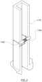
- Figure 2 shows a schematic perspective longitudinal cross sectional view of an example rectangular tube 1170 with a wick 1162 and heater coil 1164 installed.
- the location of the wick is about half way along the length of the tube. This is intended to allow the flow of air along the tube to settle before reaching the wick.
- Figure 3 shows a schematic transverse cross sectional view an example rectangular tube 1170 with a wick 1162 and heater coil 1164 installed.
- the internal width of the tube is 12 mm
- the rectangular tubes were manufactured to have same internal depth of 6 mm in order to accommodate the standardized coil and wick, however the tube internal width varied from 4.5 mm to 50 mm.
- the "tube size” is referred to as the internal width of rectangular tubes.
- the rectangular tubes with different dimensions were used to generate aerosols that were tested for particle size in a Malvern PANalytical Spraytec laser diffraction system.
- An external digital power supply was dialled to 2.6A constant current to supply 10W power to the heater coil in all experiments. Between two runs, the wick was saturated manually by applying one drop of e-liquid on each side of the wick.
- Table 1 shows a list of experiments in this study.
- the values in "calculated air velocity” column were obtained by simply dividing the flow rate by the intersection area at the centre plane of wick.
- Turbulence intensity was introduced as a quantitative parameter to assess the level of turbulence. The definition and simulation of turbulence intensity is discussed below (see section 3.2).
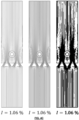
- Figures 4A-4D show air flow streamlines in the four devices used in this turbulence study.
- Figure 4A is a standard 12mm rectangular tube with wick and coil installed as explained in the previous section, with no jetting panel.
- Figure 4B has a jetting panel located 10mm below (upstream from) the wick.
- Figure 4C has the same jetting panel 5mm below the wick.
- Figure 4D has the same jetting panel 2.5mm below the wick.
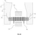
- the jetting panel has an arrangement of apertures shaped and directed in order to promote jetting from the downstream face of the panel and therefore to promote turbulent flow.
- the jetting panel can introduce turbulence downstream, and the panel causes higher level of turbulence near the wick when it is positioned closer to the wick.
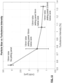
- the four geometries gave turbulence intensities of 0.55%, 0.77%, 1.06% and 1.34%, respectively, with Figure 4A being the least turbulent, and Figure 4D being the most turbulent.
- the experimental set up is shown in Figure 5 .
- the testing used a Carbolite Gero EHA 12300B tube furnace 3210 with a quartz tube 3220 to heat up the air. Hot air in the tube furnace was then led into a transparent housing 3158 that contains the EVP device 3150 to be tested.
- a thermocouple meter 3410 was used to assess the temperature of the air pulled into the EVP device. Once the EVP device was activated, the aerosol was pulled into the Spraytec laser diffraction system 3310 via a silicone connector 3320 for particle size measurement.
- pod 1 is the commercially available "myblu optimised" pod ( Figure 6 ); pod 2 is a pod featuring an extended inflow path upstream of the wick ( Figure 7 ); and pod 3 is pod with the wick located in a stagnant vaporisation chamber and the inlet air bypassing the vaporisation chamber but entraining the vapour from an outlet of the vaporisation chamber ( Figures 8A and 8B ).
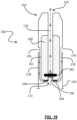
- Pod 1 shown in longitudinal cross sectional view (in the width plane) in Figure 6 , has a main housing that defines a tank 160x holding an e-liquid aerosol precursor. Mouthpiece 154x is formed at the upper part of the pod. Electrical contacts 156x are formed at the lower end of the pod. Wick 162x is held in a vaporisation chamber. The air flow direction is shown using arrows.
- Pod 2 shown in longitudinal cross sectional view (in the width plane) in Figure 7 , has a main housing that defines a tank 160y holding an e-liquid aerosol precursor. Mouthpiece 154y is formed at the upper part of the pod. Electrical contacts 156y are formed at the lower end of the pod. Wick 162y is held in a vaporisation chamber. The air flow direction is shown using arrows. Pod 2 has an extended inflow path (plenum chamber 157y) with a flow conditioning element 159y, configured to promote reduced turbulence at the wick 162y.
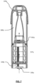
- Figure 8A shows a schematic longitudinal cross sectional view of pod 3.
- Figure 8B shows a schematic longitudinal cross sectional view of the same pod 3 in a direction orthogonal to the view taken in Figure 8A .
- Pod 3 has a main housing that defines a tank 160z holding an e-liquid aerosol precursor. Mouthpiece 154z is formed at the upper part of the pod. Electrical contacts 156z are formed at the lower end of the pod. Wick 162z is held in a vaporisation chamber. The air flow direction is shown using arrows.
- Pod 3 uses a stagnant vaporiser chamber, with the air inlets bypassing the wick and picking up the vapour/aerosol downstream of the wick.
- Air velocity in the vicinity of the wick is believed to play an important role in affecting particle size.
- the air velocity was calculated by dividing the flow rate by the intersection area, which is referred to as "calculated velocity" in this work. This involves a very crude simplification that assumes velocity distribution to be homogeneous across the intersection area.
- the CFD model uses a laminar single-phase flow setup.
- the outlet was configured to a corresponding flowrate
- the inlet was configured to be pressure-controlled
- the wall conditions were set as "no slip”.
- a 1 mm wide ring-shaped domain (wick vicinity) was created around the wick surface, and domain probes were implemented to assess the average and maximum magnitudes of velocity in this ring-shaped wick vicinity domain.
- the CFD model outputs the average velocity and maximum velocity in the vicinity of the wick for each set of experiments carried out in section 2.1. The outcomes are reported in Table 2.
- turbulence intensity values represent higher levels of turbulence.
- turbulence intensity below 1% represents a low-turbulence case
- turbulence intensity between 1% and 5% represents a medium-turbulence case
- turbulence intensity above 5% represents a high-turbulence case.
- Turbulence intensity was assessed within the volume up to 1 mm away from the wick surface (defined as the wick vicinity domain). For the four experiments explained in section 2.2, the turbulence intensities are 0.55%, 0.77%, 1.06% and 1.34%, respectively, as also shown in Figures 4A-4D .
- the cooling rate modelling involves three coupling models in COMSOL Multiphysics: 1) laminar two-phase flow; 2) heat transfer in fluids, and 3) particle tracing.
- the model is setup in three steps:
- the model outputs average vapour temperature at each time steps.
- a MATLAB script was then created to find the time step when the vapour cools to a target temperature (50°C or 75°C), based on which the vapour cooling rates were obtained (Table 3).
- Table 3 Average vapour cooling rate obtained from Multiphysics modelling Tube size [mm] Flow rate [lpm] Cooling rate to 50°C [°C/ms] Cooling rate to 75°C [°C/ms] 1.3 Ipm 4.5 1.3 11.4 44.7 6 1.3 5.48 14.9 7 1.3 3.46 7.88 8 1.3 2.24 5.15 constant flow rate 10 1.3 1.31 2.85 12 1.3 0.841 1.81 20 1.3 0* 0.536 50 1.3 0 0 2.0 Ipm 4.5 2.0 19.9 670 5 2.0 13.3 67 6 2.0 8.83 26.8 constant flow rate 8 2.0 3.61 8.93 12 2.0 1.45 3.19 20 2.0 0.395 0.761 50 2.0 0 0 * Zero cooling rate when the average vapour temperature is still above target temperature after 0.5
- Particle size measurement results for the rectangular tube testing are shown in Table 4.
- Table 4 For every tube size and flow rate combination, five repetition runs were carried out in the Spraytec laser diffraction system. The Dv50 values from five repetition runs were averaged, and the standard deviations were calculated to indicate errors, as shown in Table 4.
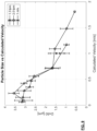
- the particle size (Dv50) experimental results are plotted against calculated air velocity in Figure 9 .
- the graph shows a strong correlation between particle size and air velocity.
- Figure 10 shows the results of three experiments with highly different setup arrangements: 1) 5mm tube measured at 1.4 lpm flow rate with Reynolds number of 155; 2) 8mm tube measured at 2.8 lpm flow rate with Reynolds number of 279; and 3) 20mm tube measured at 8.6 lpm flow rate with Reynolds number of 566. It is relevant that these setup arrangements have one similarity: the air velocities are all calculated to be 1 m/s.
- Figure 10 shows that, although these three sets of experiments have different tube sizes, flow rates and Reynolds numbers, they all delivered similar particle sizes, as the air velocity was kept constant. These three data points were also plotted out in Figure 9 (1 m/s data with star marks) and they tie in nicely into particle size-air velocity trendline.
- the particle size measurement data were plotted against the average velocity ( Figure 11 ) and maximum velocity ( Figure 12 ) in the vicinity of the wick, as obtained from CFD modelling.
- the data in these two graphs indicates that in order to obtain an aerosol with Dv50 larger than 1 ⁇ m, the average velocity should be less than or equal to 1.2 m/s in the vicinity of the wick and the maximum velocity should be less than or equal to 2.0 m/s in the vicinity of the wick.
- the average velocity should be less than or equal to 0.6 m/s in the vicinity of the wick and the maximum velocity should be less than or equal to 1.2 m/s in the vicinity of the wick.
- typical commercial EVP devices deliver aerosols with Dv50 around 0.5 ⁇ m, and there is no commercially available device that can deliver aerosol with Dv50 exceeding 1 ⁇ m. It is considered that typical commercial EVP devices have average velocity of 1.5-2.0 m/s in the vicinity of the wick.
- turbulence intensity is a quantitative characteristic that indicates the level of turbulence.
- four tubes of different turbulence intensities were used to general aerosols which were measured in the Spraytec laser diffraction system.
- the particle size (Dv50) experimental results are plotted against turbulence intensity in Figure 13 .
- the graph suggests a correlation between particle size and turbulence intensity, that lower turbulence intensity is beneficial for obtaining larger particle size. It is noted that when turbulence intensity is above 1% (medium-turbulence case), there are relatively large measurement fluctuations. In Figure 13 , the tube with a jetting panel 10mm below the wick has the largest error bar, because air jets become unpredictable near the wick after traveling through a long distance.
- the 12mm standard rectangular tube (without jetting panel) delivers above 3 ⁇ m particle size (Dv50).
- the particle size values reduced by at least a half when jetting panels were added to introduce turbulence.
- Figure 14 shows the high temperature testing results. Larger particle sizes were observed from all 3 pods when the temperature of inlet air increased from room temperature (23°C) to 50 °C. When the pods were heated as well, two of the three pods saw even larger particle size measurement results, while pod 2 was unable to be measured due to significant amount of leakage.
- laminar flow allows slow and gradual mixing between cold air and hot vapour, which means the vapour can cool down in slower rate when the airflow is laminar, resulting in larger particle size.
- vapour cooling rates for each tube size and flow rate combination were obtained via multiphysics simulation.
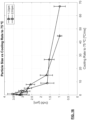
- particle size measurement results were plotted against vapour cooling rate to 50°C and 75°C, respectively.
- the apparatus in order to obtain an aerosol with Dv50 larger than 1 ⁇ m, the apparatus should be operable to require more than 16 ms for the vapour to cool to 50°C, or an equivalent (simplified to an assumed linear) cooling rate being slower than 10 °C/ms.
- the apparatus in order to obtain an aerosol with Dv50 larger than 1 ⁇ m, the apparatus should be operable to require more than 4.5 ms for the vapour to cool to 75°C, or an equivalent (simplified to an assumed linear) cooling rate slower than 30 °C/ms.
- the apparatus should be operable to require more than 32 ms for the vapour to cool to 50°C, or an equivalent (simplified to an assumed linear) cooling rate being slower than 5 °C/ms.
- the apparatus in order to obtain an aerosol with Dv50 of 2 ⁇ m or larger, should be operable to require more than 13 ms for the vapour to cool to 75°C, or an equivalent (simplified to an assumed linear) cooling rate slower than 10 °C/ms.
- particle size (Dv50) of aerosols generated in a set of rectangular tubes was studied in order to decouple different factors (flow rate, air velocity, Reynolds number, tube size) affecting aerosol particle size. It is considered that air velocity is an important factor affecting particle size - slower air velocity leads to larger particle size. When air velocity was kept constant, the other factors (flow rate, Reynolds number, tube size) has low influence on particle size.
- a smoking substitute apparatus comprising:
- a smoking substitute system including the smoking substitute apparatus of any of clauses A1 to A11 and a main body.
- A14 The smoking substitute system of clause A13, wherein the main body includes a processor configured to activate the first vaporiser and second vaporiser simultaneously in response to a puff detection.
Landscapes
- Catching Or Destruction (AREA)
- Feeding, Discharge, Calcimining, Fusing, And Gas-Generation Devices (AREA)
- Medicinal Preparation (AREA)
Applications Claiming Priority (4)
| Application Number | Priority Date | Filing Date | Title |
|---|---|---|---|
| EP19198526.6A EP3794967A1 (de) | 2019-09-20 | 2019-09-20 | Rauchersatzvorrichtung |
| EP19198551.4A EP3794968A1 (de) | 2019-09-20 | 2019-09-20 | Rauchersatzvorrichtung |
| EP20789852.9A EP3930498B1 (de) | 2019-09-20 | 2020-09-21 | Rauchersatzvorrichtung |
| PCT/EP2020/076304 WO2021053229A1 (en) | 2019-09-20 | 2020-09-21 | Smoking substitute apparatus |
Related Parent Applications (2)
| Application Number | Title | Priority Date | Filing Date |
|---|---|---|---|
| EP20789852.9A Division EP3930498B1 (de) | 2019-09-20 | 2020-09-21 | Rauchersatzvorrichtung |
| EP20789852.9A Division-Into EP3930498B1 (de) | 2019-09-20 | 2020-09-21 | Rauchersatzvorrichtung |
Publications (2)
| Publication Number | Publication Date |
|---|---|
| EP4533965A2 true EP4533965A2 (de) | 2025-04-09 |
| EP4533965A3 EP4533965A3 (de) | 2025-07-16 |
Family
ID=72840471
Family Applications (2)
| Application Number | Title | Priority Date | Filing Date |
|---|---|---|---|
| EP20789852.9A Active EP3930498B1 (de) | 2019-09-20 | 2020-09-21 | Rauchersatzvorrichtung |
| EP25151984.9A Pending EP4533965A3 (de) | 2019-09-20 | 2020-09-21 | Rauchersatzvorrichtung |
Family Applications Before (1)
| Application Number | Title | Priority Date | Filing Date |
|---|---|---|---|
| EP20789852.9A Active EP3930498B1 (de) | 2019-09-20 | 2020-09-21 | Rauchersatzvorrichtung |
Country Status (3)
| Country | Link |
|---|---|
| US (1) | US12453377B2 (de) |
| EP (2) | EP3930498B1 (de) |
| WO (1) | WO2021053229A1 (de) |
Families Citing this family (1)
| Publication number | Priority date | Publication date | Assignee | Title |
|---|---|---|---|---|
| WO2025012608A1 (en) * | 2023-07-11 | 2025-01-16 | Nicoventures Trading Limited | Vapour provision system with air flow channel |
Family Cites Families (15)
| Publication number | Priority date | Publication date | Assignee | Title |
|---|---|---|---|---|
| EP2327318A1 (de) | 2009-11-27 | 2011-06-01 | Philip Morris Products S.A. | Elektrisch erhitztes Rauchsystem mit interner oder externer Heizvorrichtung |
| US10653180B2 (en) * | 2013-06-14 | 2020-05-19 | Juul Labs, Inc. | Multiple heating elements with separate vaporizable materials in an electric vaporization device |
| GB2522727B (en) * | 2013-11-26 | 2017-01-25 | Purity Health Pharma Ltd | Pulmonary delivery devices |
| US10251426B2 (en) * | 2014-10-03 | 2019-04-09 | Fertin Pharma A/S | Electronic nicotine delivery system |
| WO2016061822A1 (zh) * | 2014-10-24 | 2016-04-28 | 惠州市吉瑞科技有限公司 | 雾化组件及电子烟 |
| WO2016082108A1 (zh) * | 2014-11-25 | 2016-06-02 | 朱晓春 | 一种电子烟雾化器发热装置 |
| US10039320B2 (en) * | 2015-05-14 | 2018-08-07 | Lunatech, Llc | Multi-chambered vaporizer and blend control |
| GB201511349D0 (en) * | 2015-06-29 | 2015-08-12 | Nicoventures Holdings Ltd | Electronic aerosol provision systems |
| US9943116B2 (en) * | 2015-11-17 | 2018-04-17 | Lunatech, Llc | Electronic vapor device warning system |
| CN120586220A (zh) * | 2016-01-11 | 2025-09-05 | Syqe医药有限公司 | 个人用蒸发装置 |
| CN205831076U (zh) * | 2016-07-01 | 2016-12-28 | 林光榕 | 具有平行双雾化单元的电子烟雾化器 |
| DE102017119521A1 (de) | 2017-08-25 | 2019-02-28 | Hauni Maschinenbau Gmbh | Verdampfereinheit für einen Inhalator und Verfahren zum Steuern einer Verdampfereinheit |
| GB201714564D0 (en) | 2017-09-11 | 2017-10-25 | British American Tobacco Investments Ltd | Heater for aerosol generating device and device |
| CN108308721B (zh) * | 2018-04-17 | 2022-07-19 | 深圳市卓力能技术有限公司 | 一种多油舱电子烟 |
| WO2020112734A1 (en) * | 2018-11-27 | 2020-06-04 | Blackship Technologies Development Llc | Micro-vaporizer with multiple liquid reservoirs |
-
2020
- 2020-09-21 WO PCT/EP2020/076304 patent/WO2021053229A1/en not_active Ceased
- 2020-09-21 EP EP20789852.9A patent/EP3930498B1/de active Active
- 2020-09-21 EP EP25151984.9A patent/EP4533965A3/de active Pending
-
2022
- 2022-03-15 US US17/694,919 patent/US12453377B2/en active Active
Also Published As
| Publication number | Publication date |
|---|---|
| US20220192268A1 (en) | 2022-06-23 |
| US12453377B2 (en) | 2025-10-28 |
| WO2021053229A1 (en) | 2021-03-25 |
| EP3930498A1 (de) | 2022-01-05 |
| EP4533965A3 (de) | 2025-07-16 |
| EP3930498B1 (de) | 2025-02-19 |
Similar Documents
| Publication | Publication Date | Title |
|---|---|---|
| EP3795009A1 (de) | Rauchersatzvorrichtung | |
| EP3930518B1 (de) | Rauchersatzvorrichtung | |
| EP3794971A1 (de) | Rauchersatzvorrichtung | |
| EP3930496A1 (de) | Rauchersatzvorrichtung | |
| EP3930498B1 (de) | Rauchersatzvorrichtung | |
| EP3930510B1 (de) | Rauchersatzvorrichtung | |
| EP3930513B1 (de) | Rauchersatzvorrichtung | |
| EP3930516B1 (de) | Rauchersatzvorrichtung | |
| EP3795013A1 (de) | Rauchersatzvorrichtung | |
| EP3794988A1 (de) | Rauchersatzvorrichtung | |
| EP3794975A1 (de) | Rauchersatzvorrichtung | |
| EP3794969A1 (de) | Rauchersatzvorrichtung | |
| EP3930515B1 (de) | Rauchersatzvorrichtung | |
| EP3930514B1 (de) | Rauchersatzvorrichtung | |
| EP3794968A1 (de) | Rauchersatzvorrichtung | |
| EP3794967A1 (de) | Rauchersatzvorrichtung | |
| EP3794980A1 (de) | Rauchersatzvorrichtung | |
| EP3795003A1 (de) | Rauchersatzvorrichtung | |
| EP3795001A1 (de) | Rauchersatzvorrichtung | |
| EP3795002A1 (de) | Rauchersatzvorrichtung | |
| EP3795012A1 (de) | Rauchersatzvorrichtung | |
| EP3794974A1 (de) | Rauchersatzvorrichtung | |
| EP3794972A1 (de) | Rauchersatzvorrichtung | |
| EP3795008A1 (de) | Rauchersatzvorrichtung | |
| EP3794996A1 (de) | Rauchersatzvorrichtung |
Legal Events
| Date | Code | Title | Description |
|---|---|---|---|
| PUAI | Public reference made under article 153(3) epc to a published international application that has entered the european phase |
Free format text: ORIGINAL CODE: 0009012 |
|
| STAA | Information on the status of an ep patent application or granted ep patent |
Free format text: STATUS: THE APPLICATION HAS BEEN PUBLISHED |
|
| AC | Divisional application: reference to earlier application |
Ref document number: 3930498 Country of ref document: EP Kind code of ref document: P |
|
| AK | Designated contracting states |
Kind code of ref document: A2 Designated state(s): AL AT BE BG CH CY CZ DE DK EE ES FI FR GB GR HR HU IE IS IT LI LT LU LV MC MK MT NL NO PL PT RO RS SE SI SK SM TR |
|
| REG | Reference to a national code |
Ref country code: DE Ref legal event code: R079 Free format text: PREVIOUS MAIN CLASS: A24F0040300000 Ipc: A24F0040100000 |
|
| PUAL | Search report despatched |
Free format text: ORIGINAL CODE: 0009013 |
|
| AK | Designated contracting states |
Kind code of ref document: A3 Designated state(s): AL AT BE BG CH CY CZ DE DK EE ES FI FR GB GR HR HU IE IS IT LI LT LU LV MC MK MT NL NO PL PT RO RS SE SI SK SM TR |
|
| RIC1 | Information provided on ipc code assigned before grant |
Ipc: A24F 40/10 20200101AFI20250612BHEP Ipc: A24F 40/30 20200101ALI20250612BHEP Ipc: A24F 40/46 20200101ALI20250612BHEP |
|
| STAA | Information on the status of an ep patent application or granted ep patent |
Free format text: STATUS: REQUEST FOR EXAMINATION WAS MADE |
|
| 17P | Request for examination filed |
Effective date: 20260113 |