EP4533936A2 - Autonome steuerung eines erntevorsatzes - Google Patents
Autonome steuerung eines erntevorsatzes Download PDFInfo
- Publication number
- EP4533936A2 EP4533936A2 EP25153690.0A EP25153690A EP4533936A2 EP 4533936 A2 EP4533936 A2 EP 4533936A2 EP 25153690 A EP25153690 A EP 25153690A EP 4533936 A2 EP4533936 A2 EP 4533936A2
- Authority
- EP
- European Patent Office
- Prior art keywords
- crop
- cutter bar
- header
- harvesting
- reel
- Prior art date
- Legal status (The legal status is an assumption and is not a legal conclusion. Google has not performed a legal analysis and makes no representation as to the accuracy of the status listed.)
- Pending
Links
Images
Classifications
-
- A—HUMAN NECESSITIES
- A01—AGRICULTURE; FORESTRY; ANIMAL HUSBANDRY; HUNTING; TRAPPING; FISHING
- A01D—HARVESTING; MOWING
- A01D41/00—Combines, i.e. harvesters or mowers combined with threshing devices
- A01D41/12—Details of combines
- A01D41/14—Mowing tables
- A01D41/141—Automatic header control
-
- A—HUMAN NECESSITIES
- A01—AGRICULTURE; FORESTRY; ANIMAL HUSBANDRY; HUNTING; TRAPPING; FISHING
- A01D—HARVESTING; MOWING
- A01D41/00—Combines, i.e. harvesters or mowers combined with threshing devices
- A01D41/12—Details of combines
- A01D41/127—Control or measuring arrangements specially adapted for combines
- A01D41/1271—Control or measuring arrangements specially adapted for combines for measuring crop flow
-
- A—HUMAN NECESSITIES
- A01—AGRICULTURE; FORESTRY; ANIMAL HUSBANDRY; HUNTING; TRAPPING; FISHING
- A01D—HARVESTING; MOWING
- A01D57/00—Delivering mechanisms for harvesters or mowers
- A01D57/01—Devices for leading crops to the mowing apparatus
- A01D57/02—Devices for leading crops to the mowing apparatus using reels
- A01D57/04—Arrangements for changing the position of the reels
-
- A—HUMAN NECESSITIES
- A01—AGRICULTURE; FORESTRY; ANIMAL HUSBANDRY; HUNTING; TRAPPING; FISHING
- A01D—HARVESTING; MOWING
- A01D75/00—Accessories for harvesters or mowers
- A01D75/18—Safety devices for parts of the machines
- A01D75/182—Avoiding overload
Definitions
- This invention relates to a header for a combine harvester or swather where the header includes components for detecting one or more operating conditions of the header for providing at least partial autonomy of control of the operation of the header or assistance to an operator of the header to reduce the level of operator participation.
- Operator control of a harvesting machine is in many conditions a difficult task with many functions to be monitored to keep the harvesting machine cutting efficiently and effectively by avoiding poor cutting parameters or even coming to a halt due to a blockage. It is of course a general objective to make such machines more autonomous to reduce operator contribution.
- the level of autonomy can be high to allow such machines to operate wholly autonomously or can be lower so that one operator can control one or more similar machines in an array or simply to reduce the level of skill or attention of a single operator.
- a crop harvesting apparatus comprising:
- a crop harvesting machine comprising:
- a crop harvesting machine comprising:
- the system monitors the transition zone of a draper feeding system and there is provided a crop harvesting machine comprising:
- any one of the above arrangements there is provided an improvement wherein there is provided a feed roller above the rear end of the feed draper and wherein the detector monitors the movement of the crop just in front of the feed roller for changes in velocity at the transition location before entry into the feeder house.
- the vehicle comprises a swather tractor.
- condition autonomously detected is any disruption in the crop flow of the header behind the cutter bar.
- condition autonomously detected is a height of the crop which is detected by ultrasonic height sensor.
- any one of the above arrangements there is provided an improvement wherein the detection is carried out by analysis of a series of sequential images to determine changes therein wherein the images are obtained by a Camera, radar or lidar.
- the detection includes a lookup table of conditions.
- control output to the machine causes movement of the reel forwardly or rearwardly.
- the vehicle comprises a combine harvester where the center support comprises the feeder house.
- the center support comprises the feeder house.
- many of the features herein can also be applied to a header on a swather tractor.
- the header can include sickle cutting system but also the invention can in many cases be applied to a rotary header.
- the system herein can be used to monitor at least one operating condition of the header as discussed hereinafter and typically most or all of the conditions described can be monitored to maximize the autonomous operation of the system.
- the selection of conditions to be monitored depends on whether the system is intended for complete autonomous monitoring of the header operation or merely as an aid for an onboard worker who retains primary responsibility. It will be appreciated that a higher level of monitoring can allow the worker to be located at another location such as in another similar vehicle operating in tandem with the monitored vehicle or even in a central remote location controlling an array of the vehicles.
- condition autonomously detected is the rate of flow of crop on the header at one or more locations.
- condition autonomously detected is differential rates of flow of crop on the header at different locations so that a detection is made when the rate changes at one location differently from at another location. This can be indicative of a failure in the system rather than merely a change in the volume of an incoming crop.
- the condition autonomously detected is any disruption in the crop flow on the header behind the cutter bar.
- This can be used to monitor the operation of the cutter system, typically a sickle bar where individual blades can be damaged or plugged. That is the flow of material over the cutter bar and onto the table or draper of the header to be carried away by the transport system can be monitored to ensure that the flow is smooth and consistent. If any inconsistencies are located, this will be indicative of a failure in the cutting system either by a blockage or by a breakage.
- the monitoring of a long cutter bar can be carried out in zones allowing a comparison between zones to detect inconsistencies.
- the condition detected can be the rate of crop flow on the conveyor.
- the conveyor can be an auger system but more effective the monitoring can be done on a draper where the rate of flow can be detected as a speed or as a weight of volume.
- Draper or auger issues are presented by the crop mass on one (or both) sides of the header by the hesitation or complete stoppage of the crop mass on top of the conveyor. If the conveyor has an issue it may slow down or stop completely, but it is also possible that the conveyor is working fine mechanically and the crop is simply not conveying as intended.
- the arrangement herein uses at least one camera to capture video of crop flow through header in the key areas of concern mentioned above.
- the video feed is sent to a processor which utilizes motion based object/particle tracking to calculate speeds of the crop flow in visible areas.
- the software can run different comparisons. It is beneficial (but not required) to break the video into zones and calculate flow speeds in each zone as a speed and direction to represent the zone. It is also beneficial for the analysis to input key operating variable such as ground speed, draper speed, reel speed and crop type so it can refine expected crop speeds in each zone for each condition. With all the above information the software can compare speed and direction of each zone monitored relative to each other.
- the software can also compare output of each zone against lookup tables which are defined by the operating conditions present such as ground speed, reel speed, etc.
- Another area which can be monitored or detected is the effectiveness of the cutting system. This is applicable either to a sickle header or to other cutting systems particularly rotary cutters. This ineffective cutting action displays itself in the material left on the field immediately behind the cutter bar as it moves forward.
- the ineffective cutting action can be determined in some cases by the presence of a crop streak of uncut or poorly cut crop behind the cutter bar. This is typically a few inches wide due to localized failure for example by a broken cutting blade or by a blockage of crop material or soil on the cutter bar at a localized position. This streak of standing crop can be detected by height sensors such as a ultrasonic sensors or by image analysis. Other methods may also be available.
- An uncut strip of crop is left behind the cutter bar as a streak.
- the streak may be narrow or wide, but is an abrupt change in height of the stubble that indicates something is not working correctly with the cutter bar.
- the header cutting system may become plugged with soil or crop residue, and begin to push material in front of the cutter bar.
- the visual indicator for this issue is a strip of soil which has just been exposed. The color or consistency of this newly exposed soil is usually different than the soil around it, making it easy to detect for the operator.
- ultrasonic sensors one or more are mounted behind/under the header constantly read stubble height.
- a controller monitors the data received real time from the sensors, looking for anomalies in height that are substantially indicative of a knife issue causing tall stubble height. If such a condition arises a signal is sent which would indicate there is an issue, and perhaps the location of the issue on the cutter bar. Subsequent use of this signal could be a warning alarm for the operator, or may trigger an automatic response by the machine to attempt to fix the issue autonomously.
- sensors such as radar, lidar, optical, where a cameras (one or more) is mounted behind the cutter bar that monitors the ground for the entire width of the header.
- a controller analyzes the stream of images and looks for disturbances in the soil which would be consistent with cutter bar exposing soil due to a cutter bar plug. Soil of darker color, or more consistent in color (less crop material on it) are the primary indicators for the analysis. If such a condition is detected the controller alerts the operator, or initiate a machine function to attempt to clear the plug by raising the header momentarily.
- the condition detected relates to the presence of an area of lodged crop in front of the cutter bar which can be combined with a detection of the height of crop in advance of the cutter bar.
- the detection can again be carried out by analysis of a series of sequential images to determine changes therein.
- ultrasonic height detection can be used or contact sensors which engage the crop heads can be used. The output from these sensors can be used to determine an indication of crop height and to distinguish short crop from downed or lodged crop which must be treated very differently in the operation of the combine harvester.
- the lodgment of the crop is at least partly detected by an analysis of the difference of the stem angles from vertical and this difference can be obtained by image analysis looking for the angles of the stems in different images at different angles since the crop may be lying longitudinal of the direction of travel or transverse.
- the lodgment of the crop can be detected by a combination of an analysis of the difference of the stem angles from vertical and a detection of a top of the crop in advance of the cutter bar.
- the output signal obtained from the analysis can also be dependent on categorizing the degree of lodgment so as to provide an output to the harvester to tailor the action to the degree and direction of lodgment.
- the arrangement herein thus uses at least one camera to capture images or video ahead of the header, and analyze them to detect down crop.
- the primary features of lodged crop is usually reduced height (similar to short crop) but also key that the plant is no longer vertical.
- the image processing software looks for stems/leaves to determine the angle they are at and compare that to known values of standing or lodged crop of that variety. This is typically not a simple yes/no analysis because crop may only have a slight lean or may be completely horizontal or anywhere in between. It is beneficial to categorize the degree of lodge into severity ranges which each require a different response by the operator or automatic adjusting system. It would also be beneficial to identify the direction of lean, because crop leaning into or away from header would benefit from different header settings.
- a system for detecting reel wrapping where crop material extends at least partly around the reel and remains in place for more than one rotation of the reel. From this detection an output signal causes a control output to the machine which can be an indication to the operator or can autonomously cause a response from the machine typically where the reel is temporarily lifted out of the crop to allow the wrapping to be discarded.
- control output to the machine causes a reduction in ground speed.
- control output to the machine causes a halt in ground speed and raising of the cutter bar to clear a cutter bar blockage of soil and/or crop material.
- control output to the machine causes movement of the reel either downwardly to provide a more aggressive harvesting action or upwardly to release wrapping problems.
- the system tries to set the reel at a most effective operating condition for the crop conditions and ground speed so that the system causes movement of the reel to change reel height.
- the system can also cause the control output to the machine causes movement of the reel forwardly or rearwardly and to change the angle of the finger pattern around the axis of the reel.
- reel is formed in separate sections carried on separate arms across the header.
- the draper header disclosed herein thus generally consists of a left-hand and a right-hand crop conveying belt, as well as a central feed conveyor which conveys crop into a feed drum, which then feeds cut crop to the inclined conveyor in the feeder house of the combine harvester.
- header drives continue to operate normally which continues to cut crop, and convey it inward to the central feed conveyor. More cut crop material is then added to the original ball or wad of crop, further aggravating the operation of clearing the plug. This can then lead to the operator of the combine harvester being required to exit the cab of the machine to remove the ball or wad of crop material by hand. All of this reduces the overall productivity of the harvester.
- a system that stops or slows the right-hand and left-hand conveyors, which stops the inward conveyance of cut crop material to the central feed conveyor upon detection of a stall of the central feed drum or upon detection of factors which indicate or predict that such as stall is about to occur. This can also occur upon detection of a stall of the inclined conveyor of the combine harvester, or the processor of the combine harvester.
- the forward movement of the harvesting machine is controlled under the responsibility of the driver so that the halting of the machine is carried out by the driver as soon as he is informed of the detection of the blockage situation.
- controls to the machine may be provided which actually halt the forward movement of the machine on communication of the blockage situation or of the halting of the operation of the side drapers in response to the detection of the blockage situation.
- the system is also arranged to provide a delay in restarting the side drapers after the blockage is removed and the operation of the system restarts. That is, upon detection of the restarting of the stalled feed member, the drive to the side drapers is held stationary for a period of time to allow the amount of crop in the feed system to pass into the combine separation before more material is fed from the side drapers.
- the delay time is calculated from the known normal rate of feed relative to a calculation of the amount of excess material in the system. This amount can pe averaged from previous information or can be detected by measuring various parameters in the blockage itself, for example a height bunched material in the blockage. That is the left-hand and right-hand conveyors do not continue conveying for some amount of time after the original plug is successfully cleared.
- the speed of operation of the side drapers and be slowed, optionally with slowing of the forward speed of the machine to give opportunity to the system to clear the potential blockage rather than allow it to occur.
- the arrangement defined above can operate to halt the side drapers in the event of detection of or prediction of a blockage at the feed system.
- the arrangement defined above can operate to slow the side drapers in the event of prediction of a blockage at the feed system.
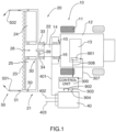
- a vehicle such as a combine harvester is shown schematically at 10 and includes ground wheels 11, a main housing 12 containing the crop processing devices, a cab 13 for the operator and a feeder house 14 for receiving the crop material and feeding it into the housing for processing.
- the details of combine harvesters are well known to a person skilled in this art so that no detail is necessary for an understanding of this invention.
- the feeder house is mounted on the housing in a manner which allows it to be raised and lowered to lift the header carried on the front of the combine.
- the feeder house includes cylinders 15, 16 which raise and lower the front end 17 of the feeder house so as to raise and lower the header as required.
- a header assembly 20 includes a header 21 and an adapter 22 which attaches the header to the feeder house 14.
- the adapter is provided to control the feeding of material into the feeder house and to provide a lifting force to the header 21 to carry it forwardly on the front 17 of the feeder house 14.
- the adapter includes float suspension using springs or a cylinder system allowing the header to float upwardly and downwardly relative to the feeder house.
- the header is generally of a conventional construction well known to a person skilled in this art and the major components include a cutter bar 23 for cutting standing crop and a crop transport device defined by a pair of drapers 24 and 25 for transporting the standing crop inwardly from ends of the header to a collection location 26 for feeding to the combine harvester.
- a reel 19 is mounted over the cutter bar 23 on arms 18 by which the height of the reel can be changed to change the spacing between reel bats of the reel and the cutter bar 23.
- the reel can slide forwardly and rearwardly of the arms 18 so as to change the position of the reel relative to the cutter bar.
- the movement of the fingers of the reel is controlled by a cam system as is well known to provide a selected finger movement pattern as the reel rotates around its axis.
- the position of the cam can be adjusted angularly around the axis so as to change the angular position at which certain finger angles are adopted. Both of these movements are actuated by control cylinders or by other means which allow them to be adjusted by the control system 301.
- the reel is formed in two sections 191 and 192 arranged side by side and carried on arms 181, 182, 183 and 184 allowing independent adjustment of the two reel sections.
- the independent adjustment can be in relation one or more of height, forward and aft position and finger angle as required. The independent adjustment can thus be used when the crop is in different conditions of height and/or lodgment across the width of the header.
- additional sensors may be provided at the location between the reels to provide an independent assessment of the crop.
- the header can run in contact with the ground so that part of the weight is carried on the float system and part applies a ground force.
- the header can include two ground engaging wheels on the header one on each side of the adapter 22.
- the number of wheels can be increased in some cases so that double wheels are used or wheels on an axle but in generally the wheels act so support the header on each side of the support provided by the adapter 22.
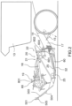
- the connection between the adapter and the header may include a suspension system 30 with a center top link 32 and two side suspension arms 33 and 34 for carrying the header on the adapter.
- the suspension arrangement allows side to side pivotal movement of the header relative to the adapter as well as vertical floating movement of the header.
- the suspension arms 33 and 34 include springs which have a spring force which can be adjusted to vary the lifting force applied to the header from the adapter.
- the suspension can use a float cylinder system which the lift force is controlled and is variable to change the ground force.
- the control system includes the control unit 300 which is responsive to input from a number of sensing systems which monitor certain operations of the header.
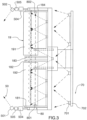
- the sensing systems include a first sensing system 50 which provides sensors 501 and 502 mounted on supports 503 at the end plates of the header and projecting forwardly from the transverse line of the cutter bar for monitoring the crop in front of the header as the crop approaches the cutter bar.
- the sensors 501, 502 can comprise devices such as a camera or lidar for generating a stream of images of the incoming crop.
- the sensors can comprise an imaging system and an ultrasonic height sensor 505 which detects the top of the incoming crop.
- the sensors for height and image can be located at the same positions on the header or at different positions for the best detection of the incoming crop.
- the height sensors can be provided as contact sensors 504 for physically engaging the heads of the crop.
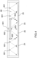
- the sensing system includes a second sensing system 60 which monitors the flow of material on the header.
- This includes a plurality of sensors 601 arranged in a row above and behind the cutter bar at a suitable fixed location on the header frame or on a support member attached to the header frame.
- the sensors provide a line of sight on to the heard immediately behind the cutter bar so as to monitor crop moving rearwardly over the cutter bar on to the drapers.
- Each sensor 601 comprises a camera which generates a series of sequential images of one portion of the header so that in combination the whole cutter bar is monitored with a series of sequential images forwarded to the control unit 300. These images are compared to generate a rate of flow of the crop material moving over the cutter bar so that any changes in crop flow rate can be detected by the control unit 300.
- the second sensing system 60 further comprises a further array of cameras 603, 604 and 605 mounted on a support 602 attached to the frame.
- the cameras 603 and 604 are located over the drapers 24 and 25 respectively so as to monitor the crop material thereon.
- the camera 605 is located over the draper 26 feeding rearwardly into the feeder house of the combine. Again these cameras generate a series of images which are compared to detect a rate of flow of the crop material.
- the sensing system includes a fourth sensing system 80 which monitors the any wrapping of crop around the reel.
- This includes at least one sensor 801 mounted at a fixed position relative to the reel at one end of the reel which generates a laser beam along the reel at one angular position around the reel so that the reel rotates past the beam.
- the beam is located at a position so that it detects the presence of crop material which occludes the beam.
- the monitoring system can distinguish the presence of material which fully wraps from crop material which merely carries back over the reel temporarily by analyzing amount of time which the beam is occluded. Thus the system can detect when crop material extends at least partly around the reel and remains in place for more than one rotation of the reel.
- the control system 300 further includes outputs 90. These include a display 901 to the operator in the cab or at a remote location. These further include a outputs 902, 903, 904 to the control system 40 of the combine to provide outputs 401, 402 and 403 for controlling ground speed, header height and reel location.
- an instruction can be provided to the combine either directly to the combine control systems or to the operator to lower the reel so that the reel bats our position immediately adjacent the cutter bar the lift the downed crop over the cutter bar.
- the controller can also use the height of reel in dependence on the output from the system defining the height of the crop canopy so as to best position the reel relative to the cutter bar to provide the best cutting action.
- the control unit also receives a speed signal which allows the control of the height of the cutter bar to be managed at a required rate of change dependent upon the forward speed of the vehicle.
- the arrangement described above provides a system for autonomously detecting one or more conditions of operation of the header to generate an output signal responsive thereto and providing in response to the signal a control output to the machine.
- the control output can provide simply a display 901 to the operator warning of the detected condition.
- the system more preferably provides the control outputs 902, 903 and 904 which provides an operation to one or more controlled components of the header and particularly the ground speed, header height and reel location.
- the system 60 can be used to detect differential rates of flow of crop on the header at different locations so that a detection is made when the rate changes at one location differently from at another location. This can be indicative of a problem in the system rather than merely a temporary reduction in total crop flow.
- the system can detect any disruption in the crop flow of the header immediately behind the cutter bar which would be indicative of a local problem on the cutter bar as indicated by a halt in crop flow at one location. Again a comparison between the different zones of the cutter bar can also provide an indication of additional problems and distinguish from anomalies not related to cutting problems such as bare patches on the field.
- the monitoring can use time as a factor to distinguish from temporary anomalies and blockages or breakages requiring specific action.
- the system 60 can also provide information on the rate of crop flow on the conveyors 24, 25 and also the rate of crop flow on the conveyor 26 at the intake to the harvesting machine.
- the system can use a comparison of rates between the different locations to indicate problems of failures in the conveying system.
- the rate of flow at the intake into the feeder house is particularly indicative of a problem in that a slowing of the rate of flow indicates bunching of the crop which is generally caused by overfeeding into the feeder house which can lead to lumpy feed into the combine or more importantly to a potential blockage.
- the condition detected by the system 70 is the presence of a crop streak of uncut or poorly cut crop behind the cutter bar or a band of disturbed soil behind the cutter bar.
- the output to the combine harvester can include the following:
- the lodgment of the crop is detected by a combination of an analysis of the difference of the stem angles from vertical and a detection of a top of the crop in advance of the cutter bar and the output signal is dependent on categorizing the degree of lodgment. This can be best controlled by generating an output signal dependent on different values from a look-up table.
Landscapes
- Life Sciences & Earth Sciences (AREA)
- Environmental Sciences (AREA)
- Harvester Elements (AREA)
- Harvesting Machines For Root Crops (AREA)
- Harvesting Machines For Specific Crops (AREA)
Applications Claiming Priority (4)
| Application Number | Priority Date | Filing Date | Title |
|---|---|---|---|
| US201862617815P | 2018-01-16 | 2018-01-16 | |
| US201862691652P | 2018-06-29 | 2018-06-29 | |
| PCT/CA2019/050047 WO2019140512A1 (en) | 2018-01-16 | 2019-01-14 | Autonomous control of a crop harvesting header |
| EP19741245.5A EP3740057B1 (de) | 2018-01-16 | 2019-01-14 | Autonome steuerung eines erntevorsatzes |
Related Parent Applications (1)
| Application Number | Title | Priority Date | Filing Date |
|---|---|---|---|
| EP19741245.5A Division EP3740057B1 (de) | 2018-01-16 | 2019-01-14 | Autonome steuerung eines erntevorsatzes |
Publications (2)
| Publication Number | Publication Date |
|---|---|
| EP4533936A2 true EP4533936A2 (de) | 2025-04-09 |
| EP4533936A3 EP4533936A3 (de) | 2025-10-01 |
Family
ID=67301647
Family Applications (2)
| Application Number | Title | Priority Date | Filing Date |
|---|---|---|---|
| EP25153690.0A Pending EP4533936A3 (de) | 2018-01-16 | 2019-01-14 | Autonome steuerung eines erntevorsatzes |
| EP19741245.5A Active EP3740057B1 (de) | 2018-01-16 | 2019-01-14 | Autonome steuerung eines erntevorsatzes |
Family Applications After (1)
| Application Number | Title | Priority Date | Filing Date |
|---|---|---|---|
| EP19741245.5A Active EP3740057B1 (de) | 2018-01-16 | 2019-01-14 | Autonome steuerung eines erntevorsatzes |
Country Status (7)
| Country | Link |
|---|---|
| US (2) | US12171163B2 (de) |
| EP (2) | EP4533936A3 (de) |
| AU (2) | AU2019209655B2 (de) |
| BR (1) | BR112020014441A2 (de) |
| CA (1) | CA3084196A1 (de) |
| HU (1) | HUE071623T2 (de) |
| WO (1) | WO2019140512A1 (de) |
Families Citing this family (33)
| Publication number | Priority date | Publication date | Assignee | Title |
|---|---|---|---|---|
| RU2747303C2 (ru) * | 2018-04-09 | 2021-05-04 | Дир Энд Компани | Система для управления рабочим параметром уборочной жатки |
| US11202410B2 (en) * | 2019-04-30 | 2021-12-21 | Deere & Company | Light-emitting mechanism on crop divider rod of harvesting header |
| US11793111B2 (en) * | 2019-11-27 | 2023-10-24 | Cnh Industrial America Llc | Harvesting head reel-mounted laser measurement |
| WO2021133755A1 (en) | 2019-12-23 | 2021-07-01 | Cnh Industrial America Llc | Reel assembly with retractable sensor arm for an agricultural header |
| US11758846B2 (en) | 2019-12-23 | 2023-09-19 | Cnh Industrial America Llc | Header control system to adjust a header of a harvester based on sensor information |
| US20210185918A1 (en) * | 2019-12-23 | 2021-06-24 | Cnh Industrial America Llc | Systems and methods for controlling a position of a reel of an agricultural header |
| US12137630B2 (en) | 2019-12-23 | 2024-11-12 | Cnh Industrial America Llc | Sensor assembly for an agricultural header |
| US11533851B2 (en) * | 2019-12-23 | 2022-12-27 | Cnh Industrial America Llc | Reel assembly for an agricultural header |
| US12029156B1 (en) * | 2020-01-09 | 2024-07-09 | Euchron, Inc. | System and method for autonomous lawn care |
| US11691824B2 (en) | 2020-02-05 | 2023-07-04 | Cnh Industrial America Llc | Slip and wrap detection systems for a conveyor belt of an agricultural header |
| US11672198B2 (en) | 2020-02-27 | 2023-06-13 | Cnh Industrial America Llc | Cut quality detection system for an agricultural mower |
| US11758844B2 (en) * | 2020-03-19 | 2023-09-19 | Deere & Company | Forward-looking perception and machine control during crop harvesting operations |
| US12256674B2 (en) * | 2020-03-19 | 2025-03-25 | Oxbo International Corporation | Detasseler and control system and method |
| US11659787B2 (en) | 2020-04-03 | 2023-05-30 | Cnh Industrial America Llc | Harvesting head reel-crop engagement |
| US12274203B2 (en) * | 2020-05-06 | 2025-04-15 | Cnh Industrial America Llc | Agricultural header with laser measurement of reel distance |
| WO2022015360A1 (en) * | 2020-07-15 | 2022-01-20 | Macdon Industries Ltd | Draper header with lean bar assembly |
| US11849672B2 (en) * | 2020-10-09 | 2023-12-26 | Deere & Company | Machine control using a predictive map |
| US11592822B2 (en) * | 2020-10-09 | 2023-02-28 | Deere & Company | Machine control using a predictive map |
| US12422847B2 (en) * | 2020-10-09 | 2025-09-23 | Deere & Company | Predictive agricultural model and map generation |
| US12035655B2 (en) * | 2020-12-01 | 2024-07-16 | Deere & Company | Control systems for automated header reel repositioning, work machines incorporating the same, and methods of operating work machines |
| US11856891B2 (en) | 2021-03-26 | 2024-01-02 | Cnh Industrial America Llc | Systems and methods for controlling an agricultural header |
| US12185653B2 (en) | 2021-04-07 | 2025-01-07 | Cnh Industrial America Llc | Mounting apparatus for agricultural header sensors |
| US20230270049A1 (en) * | 2022-02-28 | 2023-08-31 | Deere & Company | Controllable end dividers |
| DE102022107016A1 (de) * | 2022-03-24 | 2023-09-28 | Claas Selbstfahrende Erntemaschinen Gmbh | Landwirtschaftliche Erntemaschine sowie Verfahren zur Steuerung einer landwirtschaftlichen Erntemaschine |
| DE102022107015A1 (de) * | 2022-03-24 | 2023-09-28 | Claas Selbstfahrende Erntemaschinen Gmbh | Vorsatzgerät, Verfahren zur Steuerung eines Vorsatzgerätes sowie Mähdrescher |
| US12477986B2 (en) | 2022-07-13 | 2025-11-25 | Deere & Company | Radar based cutting height system for a sugarcane harvester |
| CN115250729B (zh) * | 2022-08-26 | 2023-09-01 | 甘肃农业大学 | 玉米小麦间作作用小麦收割机 |
| US20240122106A1 (en) * | 2022-10-14 | 2024-04-18 | Cnh Industrial America Llc | Stubble lean detection system for an agricultural harvester |
| US12310287B2 (en) | 2023-02-02 | 2025-05-27 | Cnh Industrial America Llc | Agricultural system and method for monitoring feeder throughput of a harvester |
| US20250000025A1 (en) * | 2023-06-30 | 2025-01-02 | Cnh Industrial America Llc | Rotary actuator system for work vehicle |
| WO2025171477A1 (en) * | 2024-02-13 | 2025-08-21 | Macdon Industries Ltd. | Method for controlling reel height |
| EP4670484A1 (de) * | 2024-06-28 | 2025-12-31 | Agco Corporation | System zur erkennung einer pflanzenbestandshöhe |
| EP4670485A1 (de) * | 2024-06-28 | 2025-12-31 | AGCO International GmbH | System und verfahren zur steuerung der höhe einer erntemaschinenhaspel |
Family Cites Families (32)
| Publication number | Priority date | Publication date | Assignee | Title |
|---|---|---|---|---|
| US4199927A (en) * | 1978-04-12 | 1980-04-29 | Craig John R | Combine reel weed shield |
| DE4406892A1 (de) * | 1994-03-03 | 1995-09-07 | Bosch Gmbh Robert | Vorrichtung zur Regelung des Bodenabstandes einer Bearbeitungseinheit einer landwirtschaftlichen Maschine |
| GB9811177D0 (en) | 1998-05-26 | 1998-07-22 | Ford New Holland Nv | Methods for generating field maps |
| DE19918552A1 (de) * | 1999-04-23 | 2000-10-26 | Deere & Co | Erntemaschine |
| US6591598B2 (en) | 2001-10-01 | 2003-07-15 | Macdon Industries Ltd. | Crop harvesting header with cam controlled movement of the reel fingers |
| DE10214648A1 (de) * | 2002-04-02 | 2003-10-16 | Claas Selbstfahr Erntemasch | Messeinrichtung an einer landwirtschaftlichen Maschine |
| DE10241216A1 (de) | 2002-09-06 | 2004-03-18 | Deere & Company, Moline | Nachweiseinrichtung zum Nachweis eines Gutstaus in einer Erntemaschine |
| CA2505431C (en) | 2005-03-22 | 2011-10-11 | Macdon Industries Ltd. | Swather with automatic reel control |
| DE102008032191A1 (de) * | 2008-07-09 | 2010-01-14 | Claas Selbstfahrende Erntemaschinen Gmbh | Selbstfahrende Erntemaschine |
| RU2402896C1 (ru) | 2009-03-10 | 2010-11-10 | Виктор Анатольевич Кущенко | Зерноуборочный комбайн |
| US8527157B2 (en) | 2010-04-28 | 2013-09-03 | Deere & Company | Agricultural combine and draper header |
| DE102010017688A1 (de) * | 2010-07-01 | 2012-01-05 | Claas Selbstfahrende Erntemaschinen Gmbh | Vorrichtung zur Erfassung und Bestimmung der Zusammensetzung von Schüttgut |
| US9629308B2 (en) * | 2011-03-11 | 2017-04-25 | Intelligent Agricultural Solutions, Llc | Harvesting machine capable of automatic adjustment |
| RU2593890C2 (ru) * | 2011-05-31 | 2016-08-10 | СиЭнЭйч ИНДАСТРИАЛ АМЕРИКА ЭлЭлСи | Система и способ работы полотенной жатки во время и после операции очистки пробки |
| DE102011086021A1 (de) | 2011-11-09 | 2013-05-16 | Deere & Company | Anordnung und Verfahren zur automatischen Dokumentation von Situationen bei der Feldarbeit |
| DE102012002795A1 (de) * | 2012-02-15 | 2013-08-22 | Claas Selbstfahrende Erntemaschinen Gmbh | Schutzvorrichtung für ein Schneidwerk eines selbstfahrenden Mähdreschers |
| EP2679085A1 (de) * | 2012-06-26 | 2014-01-01 | Norac Systems International Inc. | Höhenkontrolle |
| DE102012214079A1 (de) | 2012-08-08 | 2014-02-13 | Zürn Harvesting Gmbh & Co. Kg | Schneidwerk |
| WO2014025346A1 (en) | 2012-08-08 | 2014-02-13 | Cnh America Llc | Automatic control of relative positioning of cutter bar and reel |
| WO2014093814A1 (en) | 2012-12-14 | 2014-06-19 | Agco Corporation | Predictive load estimation through forward vision |
| US9435824B2 (en) | 2013-07-25 | 2016-09-06 | Garimella R Sarma | Circuit to extend frequency response of accelerometer |
| US9675000B2 (en) * | 2014-05-09 | 2017-06-13 | Raven Industries, Inc. | Optical flow sensing application in agricultural vehicles |
| US9807933B2 (en) | 2014-10-20 | 2017-11-07 | Cnh Industrial America Llc | Sensor equipped agricultural harvester |
| BR102016005189B1 (pt) * | 2015-03-13 | 2020-11-17 | Cnh Industrial Belgium Nv | Colheitadeira agricola |
| US9668406B2 (en) * | 2015-05-20 | 2017-06-06 | Deere & Company | Sectional yield measurement on row independent harvesting head |
| US9696162B2 (en) * | 2015-09-17 | 2017-07-04 | Deere & Company | Mission and path planning using images of crop wind damage |
| DE102015116572A1 (de) * | 2015-09-30 | 2017-03-30 | Claas Selbstfahrende Erntemaschinen Gmbh | Verfahren zum Erkennen von Störungen einer Erntegutbergungsanordnung |
| DE102016118244A1 (de) * | 2016-09-27 | 2018-03-29 | Claas Selbstfahrende Erntemaschinen Gmbh | Gutflussüberwachung einer Erntegutaufnahmevorrichtung |
| DE102017208442A1 (de) * | 2017-05-18 | 2018-11-22 | Deere & Company | Selbstlernende, Korrektureingaben berücksichtigende Anordnung zur selbsttätigen Kontrolle eines Arbeitsparameters einer Erntegutförder- und/oder -bearbeitungseinrichtung |
| US10595462B2 (en) * | 2017-06-30 | 2020-03-24 | Deere & Company | Harvester head reel segments synchronization |
| US10757859B2 (en) * | 2017-07-20 | 2020-09-01 | Deere & Company | System for optimizing platform settings based on crop state classification |
| US10813288B2 (en) * | 2018-05-31 | 2020-10-27 | Deere & Company | Automated belt speed control |
-
2019
- 2019-01-14 EP EP25153690.0A patent/EP4533936A3/de active Pending
- 2019-01-14 HU HUE19741245A patent/HUE071623T2/hu unknown
- 2019-01-14 BR BR112020014441-0A patent/BR112020014441A2/pt not_active Application Discontinuation
- 2019-01-14 US US16/769,090 patent/US12171163B2/en active Active
- 2019-01-14 WO PCT/CA2019/050047 patent/WO2019140512A1/en not_active Ceased
- 2019-01-14 CA CA3084196A patent/CA3084196A1/en active Pending
- 2019-01-14 EP EP19741245.5A patent/EP3740057B1/de active Active
- 2019-01-14 AU AU2019209655A patent/AU2019209655B2/en active Active
-
2024
- 2024-11-11 US US18/943,139 patent/US20250063987A1/en active Pending
-
2025
- 2025-01-16 AU AU2025200309A patent/AU2025200309A1/en active Pending
Also Published As
| Publication number | Publication date |
|---|---|
| CA3084196A1 (en) | 2019-07-25 |
| US12171163B2 (en) | 2024-12-24 |
| AU2019209655B2 (en) | 2024-11-14 |
| AU2019209655A1 (en) | 2020-06-25 |
| AU2025200309A1 (en) | 2025-02-13 |
| RU2020127209A3 (de) | 2022-02-17 |
| EP3740057A1 (de) | 2020-11-25 |
| EP3740057A4 (de) | 2022-02-23 |
| RU2020127209A (ru) | 2022-02-17 |
| US20250063987A1 (en) | 2025-02-27 |
| HUE071623T2 (hu) | 2025-09-28 |
| EP3740057B1 (de) | 2025-02-19 |
| BR112020014441A2 (pt) | 2020-12-01 |
| EP4533936A3 (de) | 2025-10-01 |
| US20210137006A1 (en) | 2021-05-13 |
| WO2019140512A1 (en) | 2019-07-25 |
Similar Documents
| Publication | Publication Date | Title |
|---|---|---|
| US20250063987A1 (en) | Autonomous control of a crop harvesting header | |
| US12022772B2 (en) | Agricultural header control | |
| EP2382854B1 (de) | Mähdrescher mit Mähtisch mit Förderband | |
| US9320196B2 (en) | Stripper plate adjustment | |
| US8635840B2 (en) | Device for detection and determination of the composition of bulk material | |
| CN105875030B (zh) | 多传感器作物产量确定 | |
| US20240224855A9 (en) | Deck plate automatic adjustment system and method | |
| CA2880556C (en) | Cutting unit | |
| EP4104662B1 (de) | Schneidvorrichtung | |
| EP4353063A1 (de) | Systeme und verfahren zur erkennung von ernteverlusten in einem maispflücker | |
| US20240206396A1 (en) | System and method for detecting foreign objects within an agricultural harvester | |
| EP4578260A1 (de) | Systeme und verfahren zur überwachung und anpassung des betriebs eines landwirtschaftlichen systems | |
| EP4570052A1 (de) | Systeme und verfahren zur steuerung eines maispflückers | |
| EP4360436A1 (de) | Systeme und verfahren zur ernteguterfassung für einen landwirtschaftlichen erntevorsatz | |
| RU2784488C2 (ru) | Устройство для уборки сельскохозяйственной культуры (варианты) | |
| US12127498B2 (en) | Belt-type cutting system comprising knives for cutting crops, including means for monitoring the condition of the knives | |
| EP4205529A1 (de) | Durchsatzsensor für mähdrescher | |
| EP4344526B1 (de) | Zustandsüberwachung einer bandmesseranordnung einer landwirtschaftlichen erntemaschine | |
| JP6930476B2 (ja) | コンバイン | |
| US20250351777A1 (en) | Residue profiling system | |
| JP7755812B2 (ja) | コンバイン | |
| KR102897226B1 (ko) | 콤바인 | |
| WO2024015556A1 (en) | Systems and methods for header height control | |
| CN119732255A (zh) | 经由成像处理检测作物损失的系统和方法 |
Legal Events
| Date | Code | Title | Description |
|---|---|---|---|
| PUAI | Public reference made under article 153(3) epc to a published international application that has entered the european phase |
Free format text: ORIGINAL CODE: 0009012 |
|
| STAA | Information on the status of an ep patent application or granted ep patent |
Free format text: STATUS: THE APPLICATION HAS BEEN PUBLISHED |
|
| AC | Divisional application: reference to earlier application |
Ref document number: 3740057 Country of ref document: EP Kind code of ref document: P |
|
| AK | Designated contracting states |
Kind code of ref document: A2 Designated state(s): AL AT BE BG CH CY CZ DE DK EE ES FI FR GB GR HR HU IE IS IT LI LT LU LV MC MK MT NL NO PL PT RO RS SE SI SK SM TR |
|
| REG | Reference to a national code |
Ref country code: DE Ref legal event code: R079 Free format text: PREVIOUS MAIN CLASS: A01D0075180000 Ipc: A01D0041140000 |
|
| RIC1 | Information provided on ipc code assigned before grant |
Ipc: A01D 75/18 20060101ALI20250605BHEP Ipc: A01D 57/04 20060101ALI20250605BHEP Ipc: A01D 41/127 20060101ALI20250605BHEP Ipc: A01D 57/02 20060101ALI20250605BHEP Ipc: A01D 41/14 20060101AFI20250605BHEP |
|
| PUAL | Search report despatched |
Free format text: ORIGINAL CODE: 0009013 |
|
| AK | Designated contracting states |
Kind code of ref document: A3 Designated state(s): AL AT BE BG CH CY CZ DE DK EE ES FI FR GB GR HR HU IE IS IT LI LT LU LV MC MK MT NL NO PL PT RO RS SE SI SK SM TR |
|
| RIC1 | Information provided on ipc code assigned before grant |
Ipc: A01D 41/14 20060101AFI20250827BHEP Ipc: A01D 57/02 20060101ALI20250827BHEP Ipc: A01D 41/127 20060101ALI20250827BHEP Ipc: A01D 57/04 20060101ALI20250827BHEP Ipc: A01D 75/18 20060101ALI20250827BHEP |
|
| STAA | Information on the status of an ep patent application or granted ep patent |
Free format text: STATUS: REQUEST FOR EXAMINATION WAS MADE |
|
| 17P | Request for examination filed |
Effective date: 20260108 |