EP4531509A1 - Cooling system - Google Patents
Cooling system Download PDFInfo
- Publication number
- EP4531509A1 EP4531509A1 EP23838708.8A EP23838708A EP4531509A1 EP 4531509 A1 EP4531509 A1 EP 4531509A1 EP 23838708 A EP23838708 A EP 23838708A EP 4531509 A1 EP4531509 A1 EP 4531509A1
- Authority
- EP
- European Patent Office
- Prior art keywords
- valve
- state
- outlet pipe
- liquid
- liquid outlet
- Prior art date
- Legal status (The legal status is an assumption and is not a legal conclusion. Google has not performed a legal analysis and makes no representation as to the accuracy of the status listed.)
- Pending
Links
Images


Classifications
-
- H—ELECTRICITY
- H05—ELECTRIC TECHNIQUES NOT OTHERWISE PROVIDED FOR
- H05K—PRINTED CIRCUITS; CASINGS OR CONSTRUCTIONAL DETAILS OF ELECTRIC APPARATUS; MANUFACTURE OF ASSEMBLAGES OF ELECTRICAL COMPONENTS
- H05K7/00—Constructional details common to different types of electric apparatus
- H05K7/20—Modifications to facilitate cooling, ventilating, or heating
- H05K7/20709—Modifications to facilitate cooling, ventilating, or heating for server racks or cabinets; for data centers, e.g. 19-inch computer racks
- H05K7/20718—Forced ventilation of a gaseous coolant
-
- H—ELECTRICITY
- H05—ELECTRIC TECHNIQUES NOT OTHERWISE PROVIDED FOR
- H05K—PRINTED CIRCUITS; CASINGS OR CONSTRUCTIONAL DETAILS OF ELECTRIC APPARATUS; MANUFACTURE OF ASSEMBLAGES OF ELECTRICAL COMPONENTS
- H05K7/00—Constructional details common to different types of electric apparatus
- H05K7/20—Modifications to facilitate cooling, ventilating, or heating
- H05K7/20218—Modifications to facilitate cooling, ventilating, or heating using a liquid coolant without phase change in electronic enclosures
- H05K7/20272—Accessories for moving fluid, for expanding fluid, for connecting fluid conduits, for distributing fluid, for removing gas or for preventing leakage, e.g. pumps, tanks or manifolds
-
- H—ELECTRICITY
- H05—ELECTRIC TECHNIQUES NOT OTHERWISE PROVIDED FOR
- H05K—PRINTED CIRCUITS; CASINGS OR CONSTRUCTIONAL DETAILS OF ELECTRIC APPARATUS; MANUFACTURE OF ASSEMBLAGES OF ELECTRICAL COMPONENTS
- H05K7/00—Constructional details common to different types of electric apparatus
- H05K7/20—Modifications to facilitate cooling, ventilating, or heating
- H05K7/20709—Modifications to facilitate cooling, ventilating, or heating for server racks or cabinets; for data centers, e.g. 19-inch computer racks
- H05K7/20763—Liquid cooling without phase change
-
- H—ELECTRICITY
- H05—ELECTRIC TECHNIQUES NOT OTHERWISE PROVIDED FOR
- H05K—PRINTED CIRCUITS; CASINGS OR CONSTRUCTIONAL DETAILS OF ELECTRIC APPARATUS; MANUFACTURE OF ASSEMBLAGES OF ELECTRICAL COMPONENTS
- H05K7/00—Constructional details common to different types of electric apparatus
- H05K7/20—Modifications to facilitate cooling, ventilating, or heating
- H05K7/20709—Modifications to facilitate cooling, ventilating, or heating for server racks or cabinets; for data centers, e.g. 19-inch computer racks
- H05K7/20763—Liquid cooling without phase change
- H05K7/20781—Liquid cooling without phase change within cabinets for removing heat from server blades
-
- H—ELECTRICITY
- H05—ELECTRIC TECHNIQUES NOT OTHERWISE PROVIDED FOR
- H05K—PRINTED CIRCUITS; CASINGS OR CONSTRUCTIONAL DETAILS OF ELECTRIC APPARATUS; MANUFACTURE OF ASSEMBLAGES OF ELECTRICAL COMPONENTS
- H05K7/00—Constructional details common to different types of electric apparatus
- H05K7/20—Modifications to facilitate cooling, ventilating, or heating
- H05K7/20709—Modifications to facilitate cooling, ventilating, or heating for server racks or cabinets; for data centers, e.g. 19-inch computer racks
- H05K7/20836—Thermal management, e.g. server temperature control
-
- H—ELECTRICITY
- H05—ELECTRIC TECHNIQUES NOT OTHERWISE PROVIDED FOR
- H05K—PRINTED CIRCUITS; CASINGS OR CONSTRUCTIONAL DETAILS OF ELECTRIC APPARATUS; MANUFACTURE OF ASSEMBLAGES OF ELECTRICAL COMPONENTS
- H05K7/00—Constructional details common to different types of electric apparatus
- H05K7/20—Modifications to facilitate cooling, ventilating, or heating
- H05K7/20709—Modifications to facilitate cooling, ventilating, or heating for server racks or cabinets; for data centers, e.g. 19-inch computer racks
- H05K7/20718—Forced ventilation of a gaseous coolant
- H05K7/20745—Forced ventilation of a gaseous coolant within rooms for removing heat from cabinets, e.g. by air conditioning device
-
- H—ELECTRICITY
- H05—ELECTRIC TECHNIQUES NOT OTHERWISE PROVIDED FOR
- H05K—PRINTED CIRCUITS; CASINGS OR CONSTRUCTIONAL DETAILS OF ELECTRIC APPARATUS; MANUFACTURE OF ASSEMBLAGES OF ELECTRICAL COMPONENTS
- H05K7/00—Constructional details common to different types of electric apparatus
- H05K7/20—Modifications to facilitate cooling, ventilating, or heating
- H05K7/20709—Modifications to facilitate cooling, ventilating, or heating for server racks or cabinets; for data centers, e.g. 19-inch computer racks
- H05K7/20763—Liquid cooling without phase change
- H05K7/2079—Liquid cooling without phase change within rooms for removing heat from cabinets
Definitions
- Embodiments of the present disclosure generally relate to a technical field of electronic device cooling, and more particularly, to a cooling system.
- a liquid cooling solution becomes an important technical direction for data center construction.
- a conventional liquid cooling solution is cold plate liquid cooling. Since complexity of design of a server cold plate is high, only heat of critical components such as a central processing unit (CPU) and a graphics processor (GPU) is typically dissipated to outside from the cold plate via a coolant in a general server, while heat of remaining components is taken away by an indoor air conditioning system.
- CPU central processing unit
- GPU graphics processor
- An object of the present disclosure is to provide a cooling system to at least partially solve above problems.
- a cooling system including: an air cooling part including a first cooler and a first circulation pipe connected to the first cooler, the first cooler being configured to cool a coolant inside it with an external liquid, and the first circulation pipe including a first liquid outlet pipe and a first liquid return pipe; a liquid cooling part including a second cooler and a second circulation pipe connected to the second cooler, the second cooler being configured to cool a coolant inside it with an external gas, and the second circulation pipeline including a second liquid outlet pipe and a second liquid return pipe; and a guide assembly connected between the first circulation pipeline and the second circulation pipeline and configured to: in a first state, drive a part of the coolant in the first liquid outlet pipe into the second liquid outlet pipe and guide at least a part of the coolant in the second liquid return pipe into the first liquid return pipe, and in a second state, drive a part of the coolant in the second liquid outlet pipe into the first liquid outlet pipe and guide at least a part of the coolant in the first liquid return pipe into the second liquid
- the guide assembly includes: a first circulation pump running in the first state and stopping running in the second state, the first circulation pump, upon running, driving a part of the coolant in the first liquid outlet pipe into the second liquid outlet pipe; and a second circulation pump running in the second state and stopping running in the first state, the second circulation pump, upon running, driving a part of the coolant in the second liquid outlet pipe into the first liquid outlet pipe.
- the guide assembly further includes a first valve, a second valve, a third valve, and a fourth valve; the first valve and the first circulation pump are connected in series between the first liquid outlet pipe and the second liquid outlet pipe, and the first valve is opened in the first state and closed in the second state; the second valve and the second circulation pump are connected in series between the first liquid outlet pipe and the second liquid outlet pipe, and the second valve is opened in the second state and closed in the first state; the third valve is connected between the first liquid return pipe and the second liquid return pipe, and the third valve is opened in the first state and closed in the second state; and the fourth valve is connected between the first liquid return pipe and the second liquid return pipe, and the fourth valve is opened in the second state and closed in the first state.
- the guide assembly further includes a first valve, a second valve, and a third valve; the first valve and the first circulation pump are connected in series between the first liquid outlet pipe and the second liquid outlet pipe, and the first valve is opened in the first state and closed in the second state; the second valve and the second circulation pump are connected in series between the first liquid outlet pipe and the second liquid outlet pipe, and the second valve is opened in the second state and closed in the first state; and the third valve is connected between the first liquid return pipe and the second liquid return pipe, and the third valve is opened in both the first state and the second state.
- the guide assembly further includes a first valve and a second valve; the first circulation pump and the second circulation pump are connected in parallel and are connected in series with the first valve between the first liquid outlet pipe and the second liquid outlet pipe, and the first valve is opened in both the first state and the second state; and the second valve is connected between the first liquid return pipe and the second liquid return pipe, and the second valve is opened in both the first state and the second state.
- the guide assembly further includes a first valve and a second valve; the first valve, the first circulation pump and the second circulation pump are connected in series between the first liquid outlet pipe and the second liquid outlet pipe, and the first valve is opened in both the first state and the second state; and the second valve is connected between the first liquid return pipe and the second liquid return pipe, and the second valve is opened in both the first state and the second state.
- the guide assembly includes: a liquid storage cavity connected to the first liquid outlet pipe and the second liquid outlet pipe through a valve, and configured to receive the coolant from the first liquid outlet pipe in the first state and receive the coolant from the second liquid outlet pipe in the second state; and a third circulation pump connected to the liquid storage cavity and configured to drive a coolant in the liquid storage cavity to the second liquid outlet pipe in the first state and drive the coolant in the liquid storage cavity to the first liquid outlet pipe in the second state.
- the guide assembly further includes a first valve, a second valve, a third valve, and a fourth valve; the first valve is connected between the first liquid outlet pipe and the liquid storage cavity, and the first valve is opened in the first state and closed in the second state; the second valve is connected between the second liquid outlet pipe and the liquid storage cavity, and the second valve is opened in the second state and closed in the first state; the third valve is connected between the first liquid outlet pipe and an outlet of the third circulation pump, and the third valve is opened in the second state and closed in the first state; and the fourth valve is connected between the outlet of the third circulation pump and the second liquid outlet pipe, and the fourth valve is opened in the first state and closed in the second state.
- the guide assembly further includes a fifth valve connected between the first liquid return pipe and the second liquid return pipe, and the fifth valve is opened in both the first state and the second state.
- the first cooler includes a cooling tower, and/or the second cooler includes a dry cooler.
- an air temperature difference in different seasons may be utilized to supplement cold between the air cooling part and the liquid cooling part supplemented, and advantages of the first cooler and the second cooler are fully utilized.
- the second cooler may be utilized to supplement cold to the air cooling part, a natural cooling proportion is improved, and power supply efficiency (PUE) and water resource utilization rate (WUE) are remarkably reduced.
- PUE power supply efficiency
- WUE water resource utilization rate
- the first cooler can be utilized to supplement the liquid cooling part, so that an initial investment cost and an occupied area of the second cooler are saved.
- the term “including” and deformation thereof represent openness, i.e., “including but not limited to”. Unless specifically stated, the term “or” means “and/or”. The term “based on” means “based at least in part on”. The terms “an example embodiment” and “an embodiment” mean “at least one example embodiment”. The term “another embodiment” means “at least one further embodiment”. The terms “first,” “second,” and the like may refer to different or identical object.
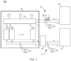
- FIG. 1 illustrates a schematic structural diagram of a conventional cooling system 100.
- the cooling system 100 described herein generally includes an air cooling part 2 and a liquid cooling part 3.
- the liquid cooling part 3 is configured to take away heat of key components such as a CPU and a GPU in a cabinet 9, and the air cooling part 2 is configured to take away heat of other components in the cabinet 9.
- the air cooling part 2 includes a first cooler 21 and a first circulation pipeline 22 connected to the first cooler 21.
- the first cooler 21 is configured to cool a coolant inside it with an external liquid.
- the first cooler 21 may be a cooling tower, and the coolant inside it may be cooled with sprayed cooling water.
- the first circulation pipeline 22 includes a first liquid outlet pipe 221 and a first liquid return pipe 222. The coolant cooled by external cooling water in the first cooler 21 may flow out via the first liquid outlet pipe 221, and warmed coolant circulated in the air cooling part 2 may be returned to the first cooler 21 via the first liquid return pipe 222, and then cooled by the first cooler 21.
- the cooling tower is merely an example of the first cooler 21, and in the embodiments according to the present disclosure, the first cooler 21 may be other types of coolers that utilize an external liquid to cool the coolant inside it, which is not limited in the embodiments of the present disclosure.
- the air cooling part 2 further includes a wind wall 23 disposed in a room cold pool 8.
- the air wall 23 may be provided with a heat dissipation pipe communicating with the first liquid outlet pipe 221 and the first liquid return pipe 222, so that the coolant may flow into the heat dissipation pipe from the first liquid outlet pipe 221 and flow into the first liquid return pipe 222 from the heat dissipation pipe.
- the air wall 23 may also be provided with a fan which is configured to drive an air flow in the cabinet 9 to flow through the air wall 23, so that a hot air from the cabinet 9 is cooled by the heat dissipation pipe in the air wall 23, and a cooled air is discharged into a room cold pool 8.
- the coolant in the heat dissipation pipe of the air wall 23 is heated due to heat absorption, and a heated coolant may flow back to the first cooler 21 via the first liquid return pipe 222, and then cooled by the external cooling water again in the first cooler 21 for next circulation.
- a closed gas passage 7 may be formed between the cabinet 9 and the air wall 23, so that the gas from the cabinet 9 may be guided into the air wall 23 via the gas passage 7.
- the air wall 23 is merely exemplary, and other types of gas driving apparatus or arrangements are possible.
- the air cooling part 2 may include an inter-column air conditioner disposed next to each cabinet 9, and the inter-column air conditioner is connected to the first liquid outlet pipe 221 and the first liquid return pipe 222.
- the inter-column air conditioner may blow air to the inside of the cabinet 9 laterally, thereby removing heat from components inside the cabinet 9.
- the air cooling part 2 further includes a supplementary cold source 24 according to weather and regions.
- the supplemental cold source 24 is disposed in the first liquid outlet pipe 221 and is configured to provide an additional cooling amount to a circulation pipeline of the air cooling part 2. Cooling capacity of the air cooling part 2 can be further improved with the supplementary cold source 24.
- the liquid cooling part 3 includes a second cooler 31 and a second circulation pipe 32 connected to the second cooler 31.
- the second cooler 31 is configured to cool a coolant inside it with an external gas.
- the second cooler 31 may be a dry cooler, which may utilize an external air to cool the coolant inside it.
- the second circulation pipeline 32 includes a second liquid outlet pipe 321 and a second liquid return pipe 322. The coolant cooled by the external gas in the second cooler 31 may flow out via the second liquid outlet pipe 321, and a warmed coolant circulated in the liquid cooling part 3 may return to the second cooler 31 via the second liquid return pipe 322, and then cooled by the second cooler 31.
- the dry cooler is merely an example of the second cooler 31, and in an embodiment according to the present disclosure, the second cooler 31 may be another type of cooler that utilizes external gas to cool the coolant inside it, which is not limited in the embodiments of the present disclosure.
- the liquid cooling part 3 further includes a cold distribution unit (CDU) 33 and a third circulation pipeline 34.
- the cold distribution unit 33 is connected between the third circulation pipeline 34 and the second circulation pipeline 32 for distributing and managing cold provided to the cabinet 9.
- the third circulation pipeline 34 is connected to a cold plate disposed in the cabinet 9 for cooling critical components such as CPUs and GPUs.
- a water supply temperature of the cold plate may be as high as 45-50°C, and a return water temperature can reach 60°C, so that the cold plate can be naturally cooled in most regions throughout a year.
- the third circulation pipeline 34 includes a third liquid outlet pipe 342 and a third liquid return pipe 341.
- the cold distribution unit 33 may provide the coolant to the cold plate via the third liquid outlet pipe 342, and the coolant heated in the cold plate may return to the cold distribution unit 33 via the third liquid return pipe 341.
- the cold distribution unit 33 may include a plate heat exchanger, the plate heat exchanger is connected to the second circulation pipeline 32 to form a first coolant circulation path, and the plate heat exchanger is connected to the third circulation pipeline 34 to form a second coolant circulation path.
- the coolant in two circulation paths may exchange heat via the plate heat exchanger.
- the second circulation pipeline 32 may be directly connected to a cold plate in the cabinet 9, so as to directly provide the coolant to critical components such as a CPU and a GPU without exchanging heat with the coolant in the two circulation paths through the cold distribution unit 33.
- the liquid cooling part 3 may include a plurality of cold distribution units 33 and a plurality of coolant circulation paths for more heat exchange, which is not limited in the embodiments of the present disclosure.
- the air cooling part 2 Due to development of electronic components, especially a gradual increase of a heating amount of components such as memory and hard disks, heat carried away by the air cooling part 2 becomes more and more considerable.
- the air cooling part 2 exchanges heat with a hot air, its heat exchange efficiency is low, and it is necessary to use the first cooler 21 such as a cooling tower to provide a lower water supply temperature to achieve effective cooling. Therefore, the air cooling part 2 has a high energy consumption and a large water consumption, which causes a data center to control power usage rate (PUE) and water resource percentage utilization rate (WUE) at a lower level even if the liquid cooling part 3 is used.
- PUE power usage rate
- WUE water resource percentage utilization rate
- the cold plate in the liquid cooling part 3 can directly deliver the coolant to a surface of a server, a heat exchange efficiency is very high, and a water temperature tends to be high, so an energy-saving and water-saving external cooling device like the second cooler 31 such as the dry cooler may be selected.
- the disadvantage of the second cooler 31 is that in summer, since a difference of outdoor temperature and coolant temperature become smaller, the heat dissipation efficiency of the second cooler 31 becomes low, in order to meet requirement of cold quantity in extreme weather, it is often need to make a heat exchange area of the second cooler 31 large, so that an initial investment is increased and an occupied area is increased, so that when a ultra-large scale data center is deployed, use of this water-saving type second cooler 31 is limited, and in turn, a less energy-saving and water-saving cooling tower and the same type of external cooling device are adopted. In addition, in a season of lower air temperature, such as winter, cold quantity generated by the second cooler 31 is exhausted, which may cause waste.
- a cooling system 100 is provided to utilize the air temperature difference in different seasons to make cold between the air cooling part 2 and the liquid cooling part 3 are mutually supplemented, thereby fully utilizing respective advantages of the first cooler 21 and the second cooler 31. Principles of the present disclosure will be described in detail below with reference to FIG. 2 to 6 .
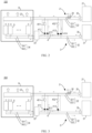
- FIG. 2 illustrates a schematic structural diagram of a cooling system 100 according to some embodiments of the present disclosure.
- the cooling system 100 includes an air cooling part 2 and a liquid cooling part 3. Structure of the air cooling part 2 and the liquid cooling part 3 shown in FIG. 2 is similar to that of the air cooling part 2 and the liquid cooling part 3 shown in FIG. 1 , and differences between them will be described in detail hereinafter, and will not be repeated for the same part.
- the air cooling part 2 further includes a coolant circulation pump 25, and the coolant circulation pump 25 is disposed in the first liquid outlet pipe 221 for driving the coolant to circulate in the air cooling part 2.
- the liquid cooling part 3 further includes a coolant circulation pump 35, and the coolant circulation pump 35 is disposed in the second liquid outlet pipe 321 for driving the coolant to circulate in the first coolant circulating path of the liquid cooling part 3.
- the cooling system 100 further includes a guide assembly 4 connected between the first circulation pipeline 22 and the second circulation pipeline 32.
- the guide assembly 4 is switchable between a first state and a second state. In the first state, the guide assembly 4 can drive a part of the coolant in the first liquid outlet pipe 221 into the second liquid outlet pipe 321 and guide at least a part of the coolant in the second liquid return pipe 322 into the first liquid return pipe 222. In the second state, the guide assembly 4 can drive a part of the coolant in the second liquid outlet pipe 321 into the first liquid outlet pipe 221 and guide at least a part of the coolant in the first liquid return pipe 222 into the second liquid return pipe 322.
- the guide assembly 4 may be placed in the first state so that a part of the coolant in the first liquid outlet pipe 221 may flow into the second liquid outlet pipe 321.
- the first cooler 21 may be utilized to supplement cold to the liquid cooling part 3, thereby saving an initial investment cost and an occupied area of the second cooler 31.
- the guide assembly 4 may be placed in the second state so that a part of the coolant in the second liquid outlet 321 may flow into the first liquid outlet 221.
- the second cooler 31 may be utilized to supplement cold to the air cooling part 2, improving the natural cooling proportion, and significantly reducing the PUE and the WUE.
- the guide assembly 4 includes a first circulation pump 401 and a second circulation pump 402.
- the first circulation pump 401 and the second circulation pump 402 are disposed in different branches.
- the first circulation pump 401 runs in the first state and stops running in the second state.
- the first circulation pump 401 upon running, can drive a part of the coolant in the first liquid outlet pipe 221 into the second liquid outlet pipe 321.
- the second circulation pump 402 runs in the second state and stops running in the first state.
- the second circulation pump 402 upon running, can drive a part of the coolant in the second liquid outlet pipe 321 into the first liquid outlet pipe 221.
- the first circulation pump 401 and the second circulation pump 402 can drive the coolant to circulate between the air cooling part 2 and the liquid cooling part 3, so as to achieve supplementing cold mutually as needed.
- the first circulation pump 401 may drive a part of the coolant in the first liquid outlet pipe 221 into the second liquid outlet pipe 321; and in the low temperature season, the second circulation pump 402 may drive a part of the coolant in the second liquid outlet pipe 321 into the first liquid outlet pipe 221.
- the guide assembly 4 further includes a first valve 411, a second valve 412, a third valve 413, and a fourth valve 414.
- the first valve 411 and the first circulation pump 401 are connected in series between the first liquid outlet pipe 221 and the second liquid outlet pipe 321.
- the first valve 411 is opened in the first state and closed in the second state.
- the second valve 412 and the second circulation pump 402 are connected in series between the first liquid outlet pipe 221 and the second liquid outlet pipe 321.
- the second valve 412 is opened in the second state and closed in the first state.
- the third valve 413 is connected between the first liquid return pipe 222 and the second liquid return pipe 322.
- the third valve 413 is opened in the first state and closed in the second state.
- the fourth valve 414 is connected between the first liquid return pipe 222 and the second liquid return pipe 322.
- the fourth valve 414 is opened in the second state and closed in the first state.
- the first circulation pump 401 is connected to the first liquid outlet pipe 221, and the first valve 411 is connected to the second liquid outlet pipe 321.
- the first circulation pump 401 and the first valve 411 may be interchanged in position, that is, the first circulation pump 401 may be connected to the second liquid outlet pipe 321, and the first valve 411 may be connected to the first liquid outlet pipe 221.
- the second circulation pump 402 is connected to the first liquid outlet pipe 221, and the second valve 412 is connected to the second liquid outlet pipe 321.
- the second circulation pump 402 and the second valve 412 may be interchanged in position, that is, the second circulation pump 402 may be connected to the second liquid outlet pipe 321, and the second valve 412 may be connected to the first liquid outlet pipe 221.
- the first circulation pump 401 runs and the second circulation pump 402 stops running. At this time, the first valve 411 and the third valve 413 are opened, and the second valve 412 and the fourth valve 414 are closed. With such an arrangement, the first circulation pump 401 may drive a part of the coolant in the first liquid outlet pipe 221 into the second liquid outlet pipe 321; while at least a part of the coolant in the second liquid return pipe 322 may be guided into the first liquid return pipe 222 via the third valve 413 and flow into the first cooler 21 for cooling again.
- the second circulation pump 402 runs and the first circulation pump 401 stops running.
- the second valve 412 and the fourth valve 414 are opened, and the first valve 411 and the third valve 413 are closed.
- the second circulation pump 402 may drive a part of the coolant in the second liquid outlet pipe 321 into the first liquid outlet pipe 221; while at least a part of the coolant in the first liquid return pipe 222 may be guided into the second liquid return pipe 322 via the fourth valve 414 and flow into the second cooler 31 for cooling again. Therefore, when the outdoor temperature is lower, a heat exchange efficiency of the second cooler 31 is high, and cold quantity of the second cooler 31 may be provided to the air cooling part 2 to help the air wall 23 to cool. In this case, the first cooler 21 may only partially run or even completely stop, to comprehensively improve the natural cooling proportion of the data center, thereby achieving a large amount of energy consumption saving and water consumption saving.
- the first circulation pump 401 and the second circulation pump 402 may both stop running and the first valve 411, the second valve 412, the third valve 413, and the fourth valve 414 may both be closed.
- the air cooling part 2 and the liquid cooling part 3 can operate independently.
- FIG. 3 illustrates a schematic structural diagram of a cooling system 100 according to some embodiments of the present disclosure. Structure of the cooling system 100 shown in FIG. 3 is similar to that of the cooling system 100 shown in FIG. 2 , and differences between them will be described in detail hereinafter, and will not be repeated for the same part.
- the guide assembly 4 includes a first circulation pump 401 and a second circulation pump 402.
- the first circulation pump 401 and the second circulation pump 402 are disposed in different branches.
- the first circulation pump 401 runs in the first state and stops running in the second state.
- the first circulation pump 401 upon running, can drive a part of the coolant in the first liquid outlet pipe 221 into the second liquid outlet pipe 321.
- the second circulation pump 402 runs in the second state and stops running in the first state.
- the second circulation pump 402 upon running, can drive a part of the coolant in the second liquid outlet pipe 321 into the first liquid outlet pipe 221.
- the guide assembly 4 further includes a first valve 411, a second valve 412, and a third valve 413.
- the first valve 411 and the first circulation pump 401 are connected in series between the first liquid outlet pipe 221 and the second liquid outlet pipe 321.
- the first valve 411 is opened in the first state and closed in the second state.
- the second valve 412 and the second circulation pump 402 are connected in series between the first liquid outlet pipe 221 and the second liquid outlet pipe 321.
- the second valve 412 is opened in the second state and closed in the first state.
- the third valve 413 is connected between the first liquid return pipe 222 and the second liquid return pipe 322.
- the third valve 413 is opened in both the first state and the second state.
- the coolant circulation between the first liquid return pipe 222 and the second liquid return pipe 322 may both be realized via a branch where the third valve 413 is opened.
- the coolant in the second liquid return pipe 322 may flow into the first liquid return pipe 222 via the third valve 413 and into the first cooler 21 for cooling again while the guide assembly 4 is in the first state; and at least a part of the coolant in the first liquid return pipe 222 may flow into the second liquid return pipe 322 via the third valve 413 and into the second cooler 31 again for cooling while the guide assembly 4 is in the second state.
- the guide assembly 4 shown in FIG. 3 has a simpler structure and saves cost.
- the first circulation pump 401 and the second circulation pump 402 may both stop running, and the first valve 411, the second valve 412, and the third valve 413 are both closed.
- the air cooling part 2 and the liquid cooling part 3 can run independently.
- FIG. 4 illustrates a schematic structural diagram of a cooling system 100 according to some embodiments of the present disclosure. Structure of the cooling system 100 shown in FIG. 4 is similar to that of the cooling system 100 shown in FIG. 3 , and differences between them will be described in detail hereinafter, and will not be repeated for the same part.
- the guide assembly 4 includes a first circulation pump 401 and a second circulation pump 402.
- the first circulation pump 401 and the second circulation pump 402 are connected in parallel.
- the first circulation pump 401 runs in the first state and stops running in the second state.
- the first circulation pump 401 upon running, can drive a part of the coolant in the first liquid outlet pipe 221 into the second liquid outlet pipe 321.
- the second circulation pump 402 runs in the second state and stops running in the first state.
- the second circulation pump 402 upon running, can drive a part of the coolant in the second liquid outlet pipe 321 into the first liquid outlet pipe 221.
- the guide assembly 4 further includes a first valve 411 and a second valve 412.
- the first circulation pump 401 and the second circulation pump 402 are connected in series with the first valve 411 between the first liquid outlet pipe 221 and the second liquid outlet pipe 321 after being connected in parallel.
- the first valve 411 is opened in both the first state and the second state.
- the second valve 412 is connected between the first liquid return pipe 222 and the second liquid return pipe 322.
- the second valve 412 is opened in both the first state and the second state.
- the first circulation pump 401 and the second circulation pump 402 are connected to the first liquid outlet pipe 221, and the first valve 411 is connected to the second liquid outlet pipe 321.
- the first circulation pump 401 and the second circulation pump 402 and the first valve 411 may be interchanged in position, that is, the first circulation pump 401 and the second circulation pump 402 may be connected to the second liquid outlet pipe 321, and the first valve 411 may be connected to the first liquid outlet pipe 221.
- both the first circulation pump 401 and the second circulation pump 402 can drive the coolant to circulate between the air cooling part 2 and the liquid cooling part 3 via the first valve 411.
- the guide assembly 4 shown in FIG. 4 has a simpler structure and saves cost.
- the first circulation pump 401 and the second circulation pump 402 may both stop running, and both the first valve 411 and the second valve 412 may be closed. In this case, the air cooling part 2 and the liquid cooling part 3 can run independently.
- FIG. 5 illustrates a schematic structural diagram of a cooling system 100 according to some embodiments of the present disclosure.
- the structure of the cooling system 100 shown in FIG. 5 is similar to that of the cooling system 100 shown in FIG. 4 , and differences between them will be described in detail hereinafter, and will not be repeated for the same part.
- the first valve 411, the first circulation pump 401 and the second circulation pump 402 are connected in series between the first liquid outlet pipe 221 and the second liquid outlet pipe 321.
- the first valve 411 is opened in both the first state and the second state.
- the first circulation pump 401 runs and the second circulation pump 402 stops running, and the first circulation pump 401 may drive a part of the coolant in the first liquid outlet pipe 221 to the second liquid outlet pipe 321 via a bypass in parallel with the second circulation pump 402 and the first valve 411.
- the first circulation pump 401 stops running and the second circulation pump 402 runs, and the second circulation pump 402 may drive a part of the coolant in the second liquid outlet pipe 321 to the first liquid outlet pipe 221 via a bypass in parallel with the first circulation pump 401 and the first valve 411.
- the first circulation pump 401 and the second circulation pump 402 may both stop running, and both the first valve 411 and the second valve 412 may be closed. In this case, the air cooling part 2 and the liquid cooling part 3 can run independently.
- FIG. 6 illustrates a schematic structural diagram of a cooling system 100 according to some embodiments of the present disclosure.
- the structure of the cooling system 100 shown in FIG. 6 is similar to that of the cooling system 100 shown in FIG. 2 to 5 , and the differences between them will be described in detail hereinafter, and will not be repeated for the same part.
- the guide assembly 4 includes a liquid storage cavity 420 and a third circulation pump 403.
- the liquid storage cavity 420 is connected to the first liquid outlet pipe 221 and the second liquid outlet pipe 321 through a valve.
- the liquid storage cavity 420 can receive the coolant from the first liquid outlet pipe 221 in the first state and the coolant from the second liquid outlet pipe 321 in the second state.
- the third circulation pump 403 is connected to the liquid storage cavity 420.
- the third circulation pump 403 drives the coolant in the liquid storage cavity 420 to the second liquid outlet pipe 321 in the first state.
- the third circulation pump 403 drives the coolant in the liquid storage cavity 420 to the first liquid outlet pipe 221 in the second state.
- liquid storage cavity 420 By providing the liquid storage cavity 420, coolant to be circulated between the air cooling part 2 and the liquid cooling part 3 can be temporarily stored, flow and pressure balance can be easily achieved, and water hammer phenomenon is reduced.
- the liquid storage cavity 420 also has an effect of storing cold quantity and supplementing cold.
- the guide assembly 4 further includes a first valve 411, a second valve 412, a third valve 413, and a fourth valve 414.
- the first valve 411 is connected between the first liquid outlet pipe 221 and the liquid storage cavity 420.
- the first valve 411 is opened in the first state and closed in the second state.
- the second valve 412 is connected between the second liquid outlet pipe 321 and the liquid storage cavity 420.
- the second valve 412 is opened in the second state and closed in the first state.
- the third valve 413 is connected between the first liquid outlet pipe 221 and the outlet of the third circulation pump 403.
- the third valve 413 is opened in the second state and closed in the first state.
- the fourth valve 414 is connected between the outlet of the third circulation pump 403 and the second liquid outlet pipe 321.
- the fourth valve 414 is opened in the first state and closed in the second state.
- the guide assembly 4 further includes a fifth valve 415 connected between the first liquid return pipe 222 and the second liquid return pipe 322.
- the fifth valve 415 is opened in both the first state and the second state.
- the third circulation pump 403 runs, the first valve 411, the fourth valve 414, and the fifth valve 415 are opened, and the second valve 412 and the third valve 413 are closed.
- the coolant in the first liquid outlet pipe 221 may flow into the liquid storage cavity 420 via the first valve 411.
- the third circulation pump 403 may drive the coolant in the liquid storage cavity 420 into the second liquid outlet pipe 321 via the fourth valve 414; while at least a part of the coolant in the second liquid return pipe 322 may be guided into the first liquid return pipe 222 via the fifth valve 415 and into the first cooler 21 for cooling again.
- the second cooler 31 does not need to be made very large in order to achieve a cold quantity requirement of the liquid cooling part 3 in extreme weather, and will have a good saving on economy.
- the third circulation pump 403 runs, the second valve 412, the third valve 413, and the fifth valve 415 are opened, and the first valve 411 and the fourth valve 414 are closed.
- the coolant in the second liquid outlet pipe 321 may flow into the liquid storage cavity 420 through the second valve 412.
- the third circulation pump 403 may drive the coolant in the liquid storage cavity 420 into the first liquid outlet pipe 221 through the third valve 413; while at least a part of the coolant in the first liquid return pipe 222 may be guided into the second liquid return pipe 322 via the fifth valve 415 and into the second cooler 31 for cooling again.
- the heat exchange efficiency of the second cooler 31 is high, and the cold quantity of the second cooler 31 may be provided to the air cooling part 2 to help the air wall 23 to cool.
- the first cooler 21 can only partially run or even completely stop, comprehensively improve the natural cooling proportion of the data center, thereby achieving a large amount of energy consumption saving and water consumption saving.
- the third circulation pump 401 may be stopped from running and the first valve 411, the second valve 412, the third valve 413, the fourth valve 414, and the fifth valve 415 may all be closed. In this case, the air cooling part 2 and the liquid cooling part 3 can run independently.
- the guide assembly 4 may include more circulation pumps and/or more valves for controlling the circulation manner of the coolant between the air cooling part 2 and the liquid cooling part 3.
- a running state of the circulation pumps and the opening/closing state of the valves may be implemented by automatic control or manual control, which is not limited in the embodiments of the present disclosure.
- the cooling system 100 has high adaptability in global range, can improve the natural cooling proportion while reducing the initial investment cost and the occupied area, and achieves extremely low PUE and WUE.
- the cooling system 100 according to the embodiment of the present disclosure is simplified in design, less in mechanical and power components, low in total cost, and convenient for large-scale popularization and deployment.
Landscapes
- Engineering & Computer Science (AREA)
- Microelectronics & Electronic Packaging (AREA)
- Physics & Mathematics (AREA)
- Thermal Sciences (AREA)
- Computer Hardware Design (AREA)
- General Engineering & Computer Science (AREA)
- Cooling Or The Like Of Electrical Apparatus (AREA)
Abstract
Description
- This application claims priority of the
Chinese invention patent application with application number 202210826177.1 and entitled "COOLING SYSTEM" filed on July 13, 2022 - Embodiments of the present disclosure generally relate to a technical field of electronic device cooling, and more particularly, to a cooling system.
- With integration and development of new generation information communication technologies such as 5G, cloud computing, big data, artificial intelligence and the like and entity economic, a data center is gradually expanding from serving a part of enterprises to serving the whole society and becomes a new infrastructure. Therefore, a problem of energy and water resource consumption brought by the data center is widely concerned worldwide.
- Energy consumption of the data center is increased, a traditional air cooling heat dissipation solution is low in heat dissipation efficiency and needs to consume a large amount of energy, and therefore a demand of the data center cannot be met increasingly in cooling capacity and economic feasibility. To this end, a liquid cooling solution becomes an important technical direction for data center construction. A conventional liquid cooling solution is cold plate liquid cooling. Since complexity of design of a server cold plate is high, only heat of critical components such as a central processing unit (CPU) and a graphics processor (GPU) is typically dissipated to outside from the cold plate via a coolant in a general server, while heat of remaining components is taken away by an indoor air conditioning system.
- At present, there is a need for an improved data center liquid cooling scheme.
- An object of the present disclosure is to provide a cooling system to at least partially solve above problems.
- In first aspect of the present disclosure, there is provided a cooling system, including: an air cooling part including a first cooler and a first circulation pipe connected to the first cooler, the first cooler being configured to cool a coolant inside it with an external liquid, and the first circulation pipe including a first liquid outlet pipe and a first liquid return pipe; a liquid cooling part including a second cooler and a second circulation pipe connected to the second cooler, the second cooler being configured to cool a coolant inside it with an external gas, and the second circulation pipeline including a second liquid outlet pipe and a second liquid return pipe; and a guide assembly connected between the first circulation pipeline and the second circulation pipeline and configured to: in a first state, drive a part of the coolant in the first liquid outlet pipe into the second liquid outlet pipe and guide at least a part of the coolant in the second liquid return pipe into the first liquid return pipe, and in a second state, drive a part of the coolant in the second liquid outlet pipe into the first liquid outlet pipe and guide at least a part of the coolant in the first liquid return pipe into the second liquid return pipe.
- In some embodiments, the guide assembly includes: a first circulation pump running in the first state and stopping running in the second state, the first circulation pump, upon running, driving a part of the coolant in the first liquid outlet pipe into the second liquid outlet pipe; and a second circulation pump running in the second state and stopping running in the first state, the second circulation pump, upon running, driving a part of the coolant in the second liquid outlet pipe into the first liquid outlet pipe.
- In some embodiments, the guide assembly further includes a first valve, a second valve, a third valve, and a fourth valve; the first valve and the first circulation pump are connected in series between the first liquid outlet pipe and the second liquid outlet pipe, and the first valve is opened in the first state and closed in the second state; the second valve and the second circulation pump are connected in series between the first liquid outlet pipe and the second liquid outlet pipe, and the second valve is opened in the second state and closed in the first state; the third valve is connected between the first liquid return pipe and the second liquid return pipe, and the third valve is opened in the first state and closed in the second state; and the fourth valve is connected between the first liquid return pipe and the second liquid return pipe, and the fourth valve is opened in the second state and closed in the first state.
- In some embodiments, the guide assembly further includes a first valve, a second valve, and a third valve; the first valve and the first circulation pump are connected in series between the first liquid outlet pipe and the second liquid outlet pipe, and the first valve is opened in the first state and closed in the second state; the second valve and the second circulation pump are connected in series between the first liquid outlet pipe and the second liquid outlet pipe, and the second valve is opened in the second state and closed in the first state; and the third valve is connected between the first liquid return pipe and the second liquid return pipe, and the third valve is opened in both the first state and the second state.
- In some embodiments, the guide assembly further includes a first valve and a second valve; the first circulation pump and the second circulation pump are connected in parallel and are connected in series with the first valve between the first liquid outlet pipe and the second liquid outlet pipe, and the first valve is opened in both the first state and the second state; and the second valve is connected between the first liquid return pipe and the second liquid return pipe, and the second valve is opened in both the first state and the second state.
- In some embodiments, the guide assembly further includes a first valve and a second valve; the first valve, the first circulation pump and the second circulation pump are connected in series between the first liquid outlet pipe and the second liquid outlet pipe, and the first valve is opened in both the first state and the second state; and the second valve is connected between the first liquid return pipe and the second liquid return pipe, and the second valve is opened in both the first state and the second state.
- In some embodiments, the guide assembly includes: a liquid storage cavity connected to the first liquid outlet pipe and the second liquid outlet pipe through a valve, and configured to receive the coolant from the first liquid outlet pipe in the first state and receive the coolant from the second liquid outlet pipe in the second state; and a third circulation pump connected to the liquid storage cavity and configured to drive a coolant in the liquid storage cavity to the second liquid outlet pipe in the first state and drive the coolant in the liquid storage cavity to the first liquid outlet pipe in the second state.
- In some embodiments, the guide assembly further includes a first valve, a second valve, a third valve, and a fourth valve; the first valve is connected between the first liquid outlet pipe and the liquid storage cavity, and the first valve is opened in the first state and closed in the second state; the second valve is connected between the second liquid outlet pipe and the liquid storage cavity, and the second valve is opened in the second state and closed in the first state; the third valve is connected between the first liquid outlet pipe and an outlet of the third circulation pump, and the third valve is opened in the second state and closed in the first state; and the fourth valve is connected between the outlet of the third circulation pump and the second liquid outlet pipe, and the fourth valve is opened in the first state and closed in the second state.
- In some embodiments, the guide assembly further includes a fifth valve connected between the first liquid return pipe and the second liquid return pipe, and the fifth valve is opened in both the first state and the second state.
- In some embodiments, the first cooler includes a cooling tower, and/or the second cooler includes a dry cooler.
- According to embodiments of the present disclosure, by arranging the guide assembly between an air cooling part and the liquid cooling part, an air temperature difference in different seasons may be utilized to supplement cold between the air cooling part and the liquid cooling part supplemented, and advantages of the first cooler and the second cooler are fully utilized. In a low-temperature season, the second cooler may be utilized to supplement cold to the air cooling part, a natural cooling proportion is improved, and power supply efficiency (PUE) and water resource utilization rate (WUE) are remarkably reduced. In a high-temperature season, the first cooler can be utilized to supplement the liquid cooling part, so that an initial investment cost and an occupied area of the second cooler are saved.
- It should be understood that content described in this content part is not intended to limit key features or important features of the embodiments of the present disclosure, nor is it intended to limit a scope of the present disclosure. Other features of the present disclosure will become readily understood from following description.
- The above and other features, advantages, and aspects of various embodiments of the present disclosure will become more apparent from following detailed description taken in conjunction with drawings. In the drawings, the same or similar reference numbers refer to the same or similar elements, wherein:
-
FIG. 1 illustrates a schematic structural diagram of a conventional cooling system; -
FIG. 2 illustrates a schematic structural diagram of a cooling system according to some embodiments of the present disclosure; -
FIG. 3 illustrates a schematic structural diagram of a cooling system according to some embodiments of the present disclosure; -
FIG. 4 illustrates a schematic structural diagram of a cooling system according to some embodiments of the present disclosure; -
FIG. 5 illustrates a schematic structural diagram of a cooling system according to some embodiments of the present disclosure; and -
FIG. 6 illustrates a schematic structural diagram of a cooling system according to some embodiments of the present disclosure. - Preferred embodiments of the present disclosure will be described in more detail below with reference to the drawings. While preferred embodiments of the present disclosure are shown in the drawings, it should be understood that the present disclosure may be implemented in various forms and should not be limited by the embodiments set forth herein. Rather, these embodiments are provided to make the present disclosure more thorough and complete, and to fully convey the scope of the present disclosure to those skilled in the art.
- As used herein, the term "including" and deformation thereof represent openness, i.e., "including but not limited to". Unless specifically stated, the term "or" means "and/or". The term "based on" means "based at least in part on". The terms "an example embodiment" and "an embodiment" mean "at least one example embodiment". The term "another embodiment" means "at least one further embodiment". The terms "first," "second," and the like may refer to different or identical object.
-
FIG. 1 illustrates a schematic structural diagram of aconventional cooling system 100. As shown inFIG. 1 , thecooling system 100 described herein generally includes anair cooling part 2 and aliquid cooling part 3. Theliquid cooling part 3 is configured to take away heat of key components such as a CPU and a GPU in acabinet 9, and theair cooling part 2 is configured to take away heat of other components in thecabinet 9. - In some embodiments, as shown in
FIG. 1 , theair cooling part 2 includes afirst cooler 21 and afirst circulation pipeline 22 connected to thefirst cooler 21. Thefirst cooler 21 is configured to cool a coolant inside it with an external liquid. For example, thefirst cooler 21 may be a cooling tower, and the coolant inside it may be cooled with sprayed cooling water. Thefirst circulation pipeline 22 includes a firstliquid outlet pipe 221 and a firstliquid return pipe 222. The coolant cooled by external cooling water in thefirst cooler 21 may flow out via the firstliquid outlet pipe 221, and warmed coolant circulated in theair cooling part 2 may be returned to thefirst cooler 21 via the firstliquid return pipe 222, and then cooled by thefirst cooler 21. - It should be understood that the cooling tower is merely an example of the
first cooler 21, and in the embodiments according to the present disclosure, thefirst cooler 21 may be other types of coolers that utilize an external liquid to cool the coolant inside it, which is not limited in the embodiments of the present disclosure. - In some embodiments, as shown in
FIG. 1 , theair cooling part 2 further includes awind wall 23 disposed in a room cold pool 8. Theair wall 23 may be provided with a heat dissipation pipe communicating with the firstliquid outlet pipe 221 and the firstliquid return pipe 222, so that the coolant may flow into the heat dissipation pipe from the firstliquid outlet pipe 221 and flow into the firstliquid return pipe 222 from the heat dissipation pipe. Theair wall 23 may also be provided with a fan which is configured to drive an air flow in thecabinet 9 to flow through theair wall 23, so that a hot air from thecabinet 9 is cooled by the heat dissipation pipe in theair wall 23, and a cooled air is discharged into a room cold pool 8. In this process, the coolant in the heat dissipation pipe of theair wall 23 is heated due to heat absorption, and a heated coolant may flow back to thefirst cooler 21 via the firstliquid return pipe 222, and then cooled by the external cooling water again in thefirst cooler 21 for next circulation. - In some embodiments, as shown in
FIG. 1 , in order to promote driving of the fan in theair wall 23 to gas in thecabinet 9, a closed gas passage 7 may be formed between thecabinet 9 and theair wall 23, so that the gas from thecabinet 9 may be guided into theair wall 23 via the gas passage 7. - It should be understood that in embodiments according to the present disclosure, the
air wall 23 is merely exemplary, and other types of gas driving apparatus or arrangements are possible. For example, in some embodiments, theair cooling part 2 may include an inter-column air conditioner disposed next to eachcabinet 9, and the inter-column air conditioner is connected to the firstliquid outlet pipe 221 and the firstliquid return pipe 222. The inter-column air conditioner may blow air to the inside of thecabinet 9 laterally, thereby removing heat from components inside thecabinet 9. - In some embodiments, as shown in
FIG. 1 , theair cooling part 2 further includes a supplementarycold source 24 according to weather and regions. The supplementalcold source 24 is disposed in the firstliquid outlet pipe 221 and is configured to provide an additional cooling amount to a circulation pipeline of theair cooling part 2. Cooling capacity of theair cooling part 2 can be further improved with the supplementarycold source 24. - In some embodiments, as shown in
FIG. 1 , theliquid cooling part 3 includes asecond cooler 31 and asecond circulation pipe 32 connected to thesecond cooler 31. Thesecond cooler 31 is configured to cool a coolant inside it with an external gas. For example, thesecond cooler 31 may be a dry cooler, which may utilize an external air to cool the coolant inside it. Thesecond circulation pipeline 32 includes a secondliquid outlet pipe 321 and a secondliquid return pipe 322. The coolant cooled by the external gas in thesecond cooler 31 may flow out via the secondliquid outlet pipe 321, and a warmed coolant circulated in theliquid cooling part 3 may return to thesecond cooler 31 via the secondliquid return pipe 322, and then cooled by thesecond cooler 31. - It should be understood that the dry cooler is merely an example of the
second cooler 31, and in an embodiment according to the present disclosure, thesecond cooler 31 may be another type of cooler that utilizes external gas to cool the coolant inside it, which is not limited in the embodiments of the present disclosure. - In some embodiments, as shown in
FIG. 1 , theliquid cooling part 3 further includes a cold distribution unit (CDU) 33 and athird circulation pipeline 34. Thecold distribution unit 33 is connected between thethird circulation pipeline 34 and thesecond circulation pipeline 32 for distributing and managing cold provided to thecabinet 9. Thethird circulation pipeline 34 is connected to a cold plate disposed in thecabinet 9 for cooling critical components such as CPUs and GPUs. A water supply temperature of the cold plate may be as high as 45-50°C, and a return water temperature can reach 60°C, so that the cold plate can be naturally cooled in most regions throughout a year. Thethird circulation pipeline 34 includes a thirdliquid outlet pipe 342 and a thirdliquid return pipe 341. Thecold distribution unit 33 may provide the coolant to the cold plate via the thirdliquid outlet pipe 342, and the coolant heated in the cold plate may return to thecold distribution unit 33 via the thirdliquid return pipe 341. Thecold distribution unit 33 may include a plate heat exchanger, the plate heat exchanger is connected to thesecond circulation pipeline 32 to form a first coolant circulation path, and the plate heat exchanger is connected to thethird circulation pipeline 34 to form a second coolant circulation path. The coolant in two circulation paths may exchange heat via the plate heat exchanger. - In some embodiments, the
second circulation pipeline 32 may be directly connected to a cold plate in thecabinet 9, so as to directly provide the coolant to critical components such as a CPU and a GPU without exchanging heat with the coolant in the two circulation paths through thecold distribution unit 33. In some other embodiments, theliquid cooling part 3 may include a plurality ofcold distribution units 33 and a plurality of coolant circulation paths for more heat exchange, which is not limited in the embodiments of the present disclosure. - Due to development of electronic components, especially a gradual increase of a heating amount of components such as memory and hard disks, heat carried away by the
air cooling part 2 becomes more and more considerable. However, since theair cooling part 2 exchanges heat with a hot air, its heat exchange efficiency is low, and it is necessary to use thefirst cooler 21 such as a cooling tower to provide a lower water supply temperature to achieve effective cooling. Therefore, theair cooling part 2 has a high energy consumption and a large water consumption, which causes a data center to control power usage rate (PUE) and water resource percentage utilization rate (WUE) at a lower level even if theliquid cooling part 3 is used. - Since the cold plate in the
liquid cooling part 3 can directly deliver the coolant to a surface of a server, a heat exchange efficiency is very high, and a water temperature tends to be high, so an energy-saving and water-saving external cooling device like thesecond cooler 31 such as the dry cooler may be selected. The disadvantage of thesecond cooler 31 is that in summer, since a difference of outdoor temperature and coolant temperature become smaller, the heat dissipation efficiency of thesecond cooler 31 becomes low, in order to meet requirement of cold quantity in extreme weather, it is often need to make a heat exchange area of thesecond cooler 31 large, so that an initial investment is increased and an occupied area is increased, so that when a ultra-large scale data center is deployed, use of this water-saving type second cooler 31 is limited, and in turn, a less energy-saving and water-saving cooling tower and the same type of external cooling device are adopted. In addition, in a season of lower air temperature, such as winter, cold quantity generated by thesecond cooler 31 is exhausted, which may cause waste. - According to the embodiments of the present disclosure, a
cooling system 100 is provided to utilize the air temperature difference in different seasons to make cold between theair cooling part 2 and theliquid cooling part 3 are mutually supplemented, thereby fully utilizing respective advantages of thefirst cooler 21 and thesecond cooler 31. Principles of the present disclosure will be described in detail below with reference toFIG. 2 to 6 . -
FIG. 2 illustrates a schematic structural diagram of acooling system 100 according to some embodiments of the present disclosure. As shown inFIG. 2 , thecooling system 100 includes anair cooling part 2 and aliquid cooling part 3. Structure of theair cooling part 2 and theliquid cooling part 3 shown inFIG. 2 is similar to that of theair cooling part 2 and theliquid cooling part 3 shown inFIG. 1 , and differences between them will be described in detail hereinafter, and will not be repeated for the same part. - In some embodiments, as shown in
FIG. 2 , theair cooling part 2 further includes acoolant circulation pump 25, and thecoolant circulation pump 25 is disposed in the firstliquid outlet pipe 221 for driving the coolant to circulate in theair cooling part 2. - In some embodiments, as shown in
FIG. 2 , theliquid cooling part 3 further includes acoolant circulation pump 35, and thecoolant circulation pump 35 is disposed in the secondliquid outlet pipe 321 for driving the coolant to circulate in the first coolant circulating path of theliquid cooling part 3. - In some embodiments, as shown in
FIG. 2 , thecooling system 100 further includes a guide assembly 4 connected between thefirst circulation pipeline 22 and thesecond circulation pipeline 32. The guide assembly 4 is switchable between a first state and a second state. In the first state, the guide assembly 4 can drive a part of the coolant in the firstliquid outlet pipe 221 into the secondliquid outlet pipe 321 and guide at least a part of the coolant in the secondliquid return pipe 322 into the firstliquid return pipe 222. In the second state, the guide assembly 4 can drive a part of the coolant in the secondliquid outlet pipe 321 into the firstliquid outlet pipe 221 and guide at least a part of the coolant in the firstliquid return pipe 222 into the secondliquid return pipe 322. - In a high temperature season (such as summer), the guide assembly 4 may be placed in the first state so that a part of the coolant in the first
liquid outlet pipe 221 may flow into the secondliquid outlet pipe 321. In this way, thefirst cooler 21 may be utilized to supplement cold to theliquid cooling part 3, thereby saving an initial investment cost and an occupied area of thesecond cooler 31. - In a low temperature season (such as winter, spring, and autumn), the guide assembly 4 may be placed in the second state so that a part of the coolant in the second
liquid outlet 321 may flow into the firstliquid outlet 221. In this way, thesecond cooler 31 may be utilized to supplement cold to theair cooling part 2, improving the natural cooling proportion, and significantly reducing the PUE and the WUE. - In some embodiments, as shown in
FIG. 2 , the guide assembly 4 includes afirst circulation pump 401 and asecond circulation pump 402. Thefirst circulation pump 401 and thesecond circulation pump 402 are disposed in different branches. Thefirst circulation pump 401 runs in the first state and stops running in the second state. Thefirst circulation pump 401, upon running, can drive a part of the coolant in the firstliquid outlet pipe 221 into the secondliquid outlet pipe 321. Thesecond circulation pump 402 runs in the second state and stops running in the first state. Thesecond circulation pump 402, upon running, can drive a part of the coolant in the secondliquid outlet pipe 321 into the firstliquid outlet pipe 221. Thefirst circulation pump 401 and thesecond circulation pump 402 can drive the coolant to circulate between theair cooling part 2 and theliquid cooling part 3, so as to achieve supplementing cold mutually as needed. For example, in the high temperature season, thefirst circulation pump 401 may drive a part of the coolant in the firstliquid outlet pipe 221 into the secondliquid outlet pipe 321; and in the low temperature season, thesecond circulation pump 402 may drive a part of the coolant in the secondliquid outlet pipe 321 into the firstliquid outlet pipe 221. - In some embodiments, as shown in
FIG. 2 , the guide assembly 4 further includes afirst valve 411, asecond valve 412, athird valve 413, and afourth valve 414. Thefirst valve 411 and thefirst circulation pump 401 are connected in series between the firstliquid outlet pipe 221 and the secondliquid outlet pipe 321. Thefirst valve 411 is opened in the first state and closed in the second state. Thesecond valve 412 and thesecond circulation pump 402 are connected in series between the firstliquid outlet pipe 221 and the secondliquid outlet pipe 321. Thesecond valve 412 is opened in the second state and closed in the first state. Thethird valve 413 is connected between the firstliquid return pipe 222 and the secondliquid return pipe 322. Thethird valve 413 is opened in the first state and closed in the second state. Thefourth valve 414 is connected between the firstliquid return pipe 222 and the secondliquid return pipe 322. Thefourth valve 414 is opened in the second state and closed in the first state. - In some embodiments, as shown in
FIG. 2 , thefirst circulation pump 401 is connected to the firstliquid outlet pipe 221, and thefirst valve 411 is connected to the secondliquid outlet pipe 321. In other embodiments, thefirst circulation pump 401 and thefirst valve 411 may be interchanged in position, that is, thefirst circulation pump 401 may be connected to the secondliquid outlet pipe 321, and thefirst valve 411 may be connected to the firstliquid outlet pipe 221. - In some embodiments, as shown in
FIG. 2 , thesecond circulation pump 402 is connected to the firstliquid outlet pipe 221, and thesecond valve 412 is connected to the secondliquid outlet pipe 321. In other embodiments, thesecond circulation pump 402 and thesecond valve 412 may be interchanged in position, that is, thesecond circulation pump 402 may be connected to the secondliquid outlet pipe 321, and thesecond valve 412 may be connected to the firstliquid outlet pipe 221. - In the first state, the
first circulation pump 401 runs and thesecond circulation pump 402 stops running. At this time, thefirst valve 411 and thethird valve 413 are opened, and thesecond valve 412 and thefourth valve 414 are closed. With such an arrangement, thefirst circulation pump 401 may drive a part of the coolant in the firstliquid outlet pipe 221 into the secondliquid outlet pipe 321; while at least a part of the coolant in the secondliquid return pipe 322 may be guided into the firstliquid return pipe 222 via thethird valve 413 and flow into thefirst cooler 21 for cooling again. Therefore, when an outdoor temperature is high, since cold quantity of thefirst cooler 21 is easier to obtain, a part of cold quantity in theair cooling part 2 may be provided to theliquid cooling part 3, and thesecond cooler 31 does not need to be made very large in order to achieve a cold quantity requirement of theliquid cooling part 3 in extreme weather, and will have a good saving on economy. - In the second state, the
second circulation pump 402 runs and thefirst circulation pump 401 stops running. At this time, thesecond valve 412 and thefourth valve 414 are opened, and thefirst valve 411 and thethird valve 413 are closed. With such an arrangement, thesecond circulation pump 402 may drive a part of the coolant in the secondliquid outlet pipe 321 into the firstliquid outlet pipe 221; while at least a part of the coolant in the firstliquid return pipe 222 may be guided into the secondliquid return pipe 322 via thefourth valve 414 and flow into thesecond cooler 31 for cooling again. Therefore, when the outdoor temperature is lower, a heat exchange efficiency of thesecond cooler 31 is high, and cold quantity of thesecond cooler 31 may be provided to theair cooling part 2 to help theair wall 23 to cool. In this case, thefirst cooler 21 may only partially run or even completely stop, to comprehensively improve the natural cooling proportion of the data center, thereby achieving a large amount of energy consumption saving and water consumption saving. - In some embodiments, when no cold circulation is required between the
air cooling part 2 and theliquid cooling part 3, thefirst circulation pump 401 and thesecond circulation pump 402 may both stop running and thefirst valve 411, thesecond valve 412, thethird valve 413, and thefourth valve 414 may both be closed. In this case, theair cooling part 2 and theliquid cooling part 3 can operate independently. -
FIG. 3 illustrates a schematic structural diagram of acooling system 100 according to some embodiments of the present disclosure. Structure of thecooling system 100 shown inFIG. 3 is similar to that of thecooling system 100 shown inFIG. 2 , and differences between them will be described in detail hereinafter, and will not be repeated for the same part. - As shown in
FIG. 3 , the guide assembly 4 includes afirst circulation pump 401 and asecond circulation pump 402. Thefirst circulation pump 401 and thesecond circulation pump 402 are disposed in different branches. Thefirst circulation pump 401 runs in the first state and stops running in the second state. Thefirst circulation pump 401, upon running, can drive a part of the coolant in the firstliquid outlet pipe 221 into the secondliquid outlet pipe 321. Thesecond circulation pump 402 runs in the second state and stops running in the first state. Thesecond circulation pump 402, upon running, can drive a part of the coolant in the secondliquid outlet pipe 321 into the firstliquid outlet pipe 221. - In some embodiments, as shown in
FIG. 3 , the guide assembly 4 further includes afirst valve 411, asecond valve 412, and athird valve 413. Thefirst valve 411 and thefirst circulation pump 401 are connected in series between the firstliquid outlet pipe 221 and the secondliquid outlet pipe 321. Thefirst valve 411 is opened in the first state and closed in the second state. Thesecond valve 412 and thesecond circulation pump 402 are connected in series between the firstliquid outlet pipe 221 and the secondliquid outlet pipe 321. Thesecond valve 412 is opened in the second state and closed in the first state. Thethird valve 413 is connected between the firstliquid return pipe 222 and the secondliquid return pipe 322. Thethird valve 413 is opened in both the first state and the second state. - Since the
third valve 413 is opened in both the first state and the second state, when the guide assembly 4 is in the first state and the second state, the coolant circulation between the firstliquid return pipe 222 and the secondliquid return pipe 322 may both be realized via a branch where thethird valve 413 is opened. For example, at least a part of the coolant in the secondliquid return pipe 322 may flow into the firstliquid return pipe 222 via thethird valve 413 and into thefirst cooler 21 for cooling again while the guide assembly 4 is in the first state; and at least a part of the coolant in the firstliquid return pipe 222 may flow into the secondliquid return pipe 322 via thethird valve 413 and into thesecond cooler 31 again for cooling while the guide assembly 4 is in the second state. Compared with the guide assembly 4 shown inFIG. 2 , the guide assembly 4 shown inFIG. 3 has a simpler structure and saves cost. - In some embodiments, when no cold circulation is required between the
air cooling part 2 and theliquid cooling part 3, thefirst circulation pump 401 and thesecond circulation pump 402 may both stop running, and thefirst valve 411, thesecond valve 412, and thethird valve 413 are both closed. In this case, theair cooling part 2 and theliquid cooling part 3 can run independently. -
FIG. 4 illustrates a schematic structural diagram of acooling system 100 according to some embodiments of the present disclosure. Structure of thecooling system 100 shown inFIG. 4 is similar to that of thecooling system 100 shown inFIG. 3 , and differences between them will be described in detail hereinafter, and will not be repeated for the same part. - As shown in
FIG. 4 , the guide assembly 4 includes afirst circulation pump 401 and asecond circulation pump 402. Thefirst circulation pump 401 and thesecond circulation pump 402 are connected in parallel. Thefirst circulation pump 401 runs in the first state and stops running in the second state. Thefirst circulation pump 401, upon running, can drive a part of the coolant in the firstliquid outlet pipe 221 into the secondliquid outlet pipe 321. Thesecond circulation pump 402 runs in the second state and stops running in the first state. Thesecond circulation pump 402, upon running, can drive a part of the coolant in the secondliquid outlet pipe 321 into the firstliquid outlet pipe 221. - In some embodiments, as shown in
FIG. 4 , the guide assembly 4 further includes afirst valve 411 and asecond valve 412. Thefirst circulation pump 401 and thesecond circulation pump 402 are connected in series with thefirst valve 411 between the firstliquid outlet pipe 221 and the secondliquid outlet pipe 321 after being connected in parallel. Thefirst valve 411 is opened in both the first state and the second state. Thesecond valve 412 is connected between the firstliquid return pipe 222 and the secondliquid return pipe 322. Thesecond valve 412 is opened in both the first state and the second state. - In some embodiments, as shown in
FIG. 4 , thefirst circulation pump 401 and thesecond circulation pump 402 are connected to the firstliquid outlet pipe 221, and thefirst valve 411 is connected to the secondliquid outlet pipe 321. In other embodiments, thefirst circulation pump 401 and thesecond circulation pump 402 and thefirst valve 411 may be interchanged in position, that is, thefirst circulation pump 401 and thesecond circulation pump 402 may be connected to the secondliquid outlet pipe 321, and thefirst valve 411 may be connected to the firstliquid outlet pipe 221. - Since the
first valve 411 is both opened in the first state and the second state, when the guide assembly 4 is in the first state and the second state, both thefirst circulation pump 401 and thesecond circulation pump 402 can drive the coolant to circulate between theair cooling part 2 and theliquid cooling part 3 via thefirst valve 411. Compared with the guide assembly 4 shown inFIG. 3 , the guide assembly 4 shown inFIG. 4 has a simpler structure and saves cost. - In some embodiments, when no cold circulation is required between the
air cooling part 2 and theliquid cooling part 3, thefirst circulation pump 401 and thesecond circulation pump 402 may both stop running, and both thefirst valve 411 and thesecond valve 412 may be closed. In this case, theair cooling part 2 and theliquid cooling part 3 can run independently. -
FIG. 5 illustrates a schematic structural diagram of acooling system 100 according to some embodiments of the present disclosure. The structure of thecooling system 100 shown inFIG. 5 is similar to that of thecooling system 100 shown inFIG. 4 , and differences between them will be described in detail hereinafter, and will not be repeated for the same part. - As shown in
FIG. 5 , thefirst valve 411, thefirst circulation pump 401 and thesecond circulation pump 402 are connected in series between the firstliquid outlet pipe 221 and the secondliquid outlet pipe 321. Thefirst valve 411 is opened in both the first state and the second state. When the guide assembly 4 is in the first state, thefirst circulation pump 401 runs and thesecond circulation pump 402 stops running, and thefirst circulation pump 401 may drive a part of the coolant in the firstliquid outlet pipe 221 to the secondliquid outlet pipe 321 via a bypass in parallel with thesecond circulation pump 402 and thefirst valve 411. When the guide assembly 4 is in the second state, thefirst circulation pump 401 stops running and thesecond circulation pump 402 runs, and thesecond circulation pump 402 may drive a part of the coolant in the secondliquid outlet pipe 321 to the firstliquid outlet pipe 221 via a bypass in parallel with thefirst circulation pump 401 and thefirst valve 411. - In some embodiments, when no cold circulation is required between the
air cooling part 2 and theliquid cooling part 3, thefirst circulation pump 401 and thesecond circulation pump 402 may both stop running, and both thefirst valve 411 and thesecond valve 412 may be closed. In this case, theair cooling part 2 and theliquid cooling part 3 can run independently. -
FIG. 6 illustrates a schematic structural diagram of acooling system 100 according to some embodiments of the present disclosure. The structure of thecooling system 100 shown inFIG. 6 is similar to that of thecooling system 100 shown inFIG. 2 to 5 , and the differences between them will be described in detail hereinafter, and will not be repeated for the same part. - In some embodiments, as shown in
FIG. 6 , the guide assembly 4 includes aliquid storage cavity 420 and athird circulation pump 403. Theliquid storage cavity 420 is connected to the firstliquid outlet pipe 221 and the secondliquid outlet pipe 321 through a valve. Theliquid storage cavity 420 can receive the coolant from the firstliquid outlet pipe 221 in the first state and the coolant from the secondliquid outlet pipe 321 in the second state. Thethird circulation pump 403 is connected to theliquid storage cavity 420. Thethird circulation pump 403 drives the coolant in theliquid storage cavity 420 to the secondliquid outlet pipe 321 in the first state. Thethird circulation pump 403 drives the coolant in theliquid storage cavity 420 to the firstliquid outlet pipe 221 in the second state. By providing theliquid storage cavity 420, coolant to be circulated between theair cooling part 2 and theliquid cooling part 3 can be temporarily stored, flow and pressure balance can be easily achieved, and water hammer phenomenon is reduced. In addition, theliquid storage cavity 420 also has an effect of storing cold quantity and supplementing cold. - In some embodiments, as shown in
FIG. 6 , the guide assembly 4 further includes afirst valve 411, asecond valve 412, athird valve 413, and afourth valve 414. Thefirst valve 411 is connected between the firstliquid outlet pipe 221 and theliquid storage cavity 420. Thefirst valve 411 is opened in the first state and closed in the second state. Thesecond valve 412 is connected between the secondliquid outlet pipe 321 and theliquid storage cavity 420. Thesecond valve 412 is opened in the second state and closed in the first state. Thethird valve 413 is connected between the firstliquid outlet pipe 221 and the outlet of thethird circulation pump 403. Thethird valve 413 is opened in the second state and closed in the first state. Thefourth valve 414 is connected between the outlet of thethird circulation pump 403 and the secondliquid outlet pipe 321. Thefourth valve 414 is opened in the first state and closed in the second state. - In some embodiments, as shown in
FIG. 6 , the guide assembly 4 further includes afifth valve 415 connected between the firstliquid return pipe 222 and the secondliquid return pipe 322. Thefifth valve 415 is opened in both the first state and the second state. - In the first state, the
third circulation pump 403 runs, thefirst valve 411, thefourth valve 414, and thefifth valve 415 are opened, and thesecond valve 412 and thethird valve 413 are closed. At this time, the coolant in the firstliquid outlet pipe 221 may flow into theliquid storage cavity 420 via thefirst valve 411. Thethird circulation pump 403 may drive the coolant in theliquid storage cavity 420 into the secondliquid outlet pipe 321 via thefourth valve 414; while at least a part of the coolant in the secondliquid return pipe 322 may be guided into the firstliquid return pipe 222 via thefifth valve 415 and into thefirst cooler 21 for cooling again. Therefore, when the outdoor temperature is high, since the cold quantity of thefirst cooler 21 is easier to obtain, a part of the cold quantity in theair cooling part 2 may be provided to theliquid cooling part 3, and thesecond cooler 31 does not need to be made very large in order to achieve a cold quantity requirement of theliquid cooling part 3 in extreme weather, and will have a good saving on economy. - In the second state, the
third circulation pump 403 runs, thesecond valve 412, thethird valve 413, and thefifth valve 415 are opened, and thefirst valve 411 and thefourth valve 414 are closed. At this time, the coolant in the secondliquid outlet pipe 321 may flow into theliquid storage cavity 420 through thesecond valve 412. Thethird circulation pump 403 may drive the coolant in theliquid storage cavity 420 into the firstliquid outlet pipe 221 through thethird valve 413; while at least a part of the coolant in the firstliquid return pipe 222 may be guided into the secondliquid return pipe 322 via thefifth valve 415 and into thesecond cooler 31 for cooling again. Therefore, when the outdoor temperature is lower, the heat exchange efficiency of thesecond cooler 31 is high, and the cold quantity of thesecond cooler 31 may be provided to theair cooling part 2 to help theair wall 23 to cool. In this case, thefirst cooler 21 can only partially run or even completely stop, comprehensively improve the natural cooling proportion of the data center, thereby achieving a large amount of energy consumption saving and water consumption saving. - In some embodiments, when no cold circulation is required between the
air cooling part 2 and theliquid cooling part 3, thethird circulation pump 401 may be stopped from running and thefirst valve 411, thesecond valve 412, thethird valve 413, thefourth valve 414, and thefifth valve 415 may all be closed. In this case, theair cooling part 2 and theliquid cooling part 3 can run independently. - It should be understood that, in the embodiments according to the present disclosure, the guide assembly 4 may include more circulation pumps and/or more valves for controlling the circulation manner of the coolant between the
air cooling part 2 and theliquid cooling part 3. In addition, in the embodiments according to the present disclosure, a running state of the circulation pumps and the opening/closing state of the valves may be implemented by automatic control or manual control, which is not limited in the embodiments of the present disclosure. - The
cooling system 100 according to the embodiments of the present disclosure has high adaptability in global range, can improve the natural cooling proportion while reducing the initial investment cost and the occupied area, and achieves extremely low PUE and WUE. In addition, thecooling system 100 according to the embodiment of the present disclosure is simplified in design, less in mechanical and power components, low in total cost, and convenient for large-scale popularization and deployment. - Various embodiments of the present disclosure have been described above, which are exemplary, not exhaustive, and are not limited to the embodiments disclosed. Many modifications and variations will be apparent to those of ordinary skill in the art without departing from the scope and spirit of illustrated embodiments. Selection of the terms used herein is intended to best explain principles of the embodiments, practical applications, or technical improvements in marketplace, or to enable others of ordinary skill in the art to understand the embodiments disclosed herein.
Claims (10)
- A cooling system (100) comprising:an air cooling part (2) comprising a first cooler (21) and a first circulation pipeline (22) connected to the first cooler (21), the first cooler (21) being configured to cool a coolant inside it with an external liquid, and the first circulation pipeline (22) comprising a first liquid outlet pipe (221) and a first liquid return pipe (222);a liquid cooling part (3) comprising a second cooler (31) and a second circulation pipeline (32) connected to the second cooler (31), the second cooler (31) being configured to cool a coolant inside it with an external gas, and the second circulation pipeline (32) comprising a second liquid outlet pipe (321) and a second liquid return pipe (322); anda guide assembly (4) connected between the first circulation pipeline (22) and the second circulation pipeline (32) and configured to: in a first state, drive a part of the coolant in the first liquid outlet pipe (221) into the second liquid outlet pipe (321) and guide at least a part of the coolant in the second liquid return pipe (322) into the first liquid return pipe (222), and in a second state, drive a part of the coolant in the second liquid outlet pipe (321) into the first liquid outlet pipe (221) and guide at least a part of the coolant in the first liquid return pipe (222) into the second liquid return pipe (322).
- The cooling system (100) of claim 1, wherein the guide assembly (4) comprises:a first circulation pump (401) running in the first state and stopping running in the second state, the first circulation pump (401), upon running, driving a part of the coolant in the first liquid outlet pipe (221) into the second liquid outlet pipe (321); anda second circulation pump (402) running in the second state and stopping running in the first state, the second circulation pump (402), upon running, driving a part of the coolant in the second liquid outlet pipe (321) into the first liquid outlet pipe (221).
- The cooling system (100) of claim 2, wherein the guide assembly (4) further comprises a first valve (411), a second valve (412), a third valve (413), and a fourth valve (414);the first valve (411) and the first circulation pump (401) are connected in series between the first liquid outlet pipe (221) and the second liquid outlet pipe (321), and the first valve (411) is opened in the first state and closed in the second state;the second valve (412) and the second circulation pump (402) are connected in series between the first liquid outlet pipe (221) and the second liquid outlet pipe (321), and the second valve (412) is opened in the second state and closed in the first state;the third valve (413) is connected between the first liquid return pipe (222) and the second liquid return pipe (322), and the third valve (413) is opened in the first state and closed in the second state; andthe fourth valve (414) is connected between the first liquid return pipe (222) and the second liquid return pipe (322), and the fourth valve (414) is opened in the second state and closed in the first state.
- The cooling system (100) of claim 2, wherein the guide assembly (4) further comprises a first valve (411), a second valve (412), and a third valve (413);the first valve (411) and the first circulation pump (401) are connected in series between the first liquid outlet pipe (221) and the second liquid outlet pipe (321), and the first valve (411) is opened in the first state and closed in the second state;the second valve (412) and the second circulation pump (402) are connected in series between the first liquid outlet pipe (221) and the second liquid outlet pipe (321), and the second valve (412) is opened in the second state and closed in the first state; andthe third valve (413) is connected between the first liquid return pipe (222) and the second liquid return pipe (322), and the third valve (413) is opened in both the first state and the second state.
- The cooling system (100) of claim 2, wherein the guide assembly (4) further comprises a first valve (411) and a second valve (412);the first circulation pump (401) and the second circulation pump (402) are connected in parallel, and are connected in series with the first valve (411) between the first liquid outlet pipe (221) and the second liquid outlet pipe (321), and the first valve (411) is opened in both the first state and the second state; andthe second valve (412) is connected between the first liquid return pipe (222) and the second liquid return pipe (322), and the second valve (412) is opened in both the first state and the second state.
- The cooling system (100) of claim 2, wherein the guide assembly (4) further comprises a first valve (411) and a second valve (412);the first valve (411), the first circulation pump (401) and the second circulation pump (402) are connected in series between the first liquid outlet pipe (221) and the second liquid outlet pipe (321), and the first valve (411) is opened in both the first state and the second state; andthe second valve (412) is connected between the first liquid return pipe (222) and the second liquid return pipe (322), and the second valve (412) is opened in both the first state and the second state.
- The cooling system (100) of claim 1, wherein the guide assembly (4) comprises:a liquid storage cavity (420) connected to the first liquid outlet pipe (221) and the second liquid outlet pipe (321) through a valve, and configured to receive the coolant from the first liquid outlet pipe (221) in the first state and receive the coolant from the second liquid outlet pipe (321) in the second state; anda third circulation pump (403) connected to the liquid storage cavity (420) and configured to drive a coolant in the liquid storage cavity (420) to the second liquid outlet pipe (321) in the first state and drive the coolant in the liquid storage cavity (420) to the first liquid outlet pipe (221) in the second state.
- The cooling system (100) of claim 7, wherein the guide assembly (4) further comprises a first valve (411), a second valve (412), a third valve (413), and a fourth valve (414);the first valve (411) is connected between the first liquid outlet pipe (221) and the liquid storage cavity (420), and the first valve (411) is opened in the first state and closed in the second state;the second valve (412) is connected between the second liquid outlet pipe (321) and the liquid storage cavity (420), and the second valve (412) is opened in the second state and closed in the first state;the third valve (413) is connected between the first liquid outlet pipe (221) and an outlet of the third circulation pump (403), and the third valve (413) is opened in the second state and closed in the first state; andthe fourth valve (414) is connected between the outlet of the third circulation pump (403) and the second liquid outlet pipe (321), and the fourth valve (414) is opened in the first state and closed in the second state.
- The cooling system (100) of claim 7, wherein the guide assembly (4) further comprises a fifth valve (415) connected between the first liquid return pipe (222) and the second liquid return pipe (322), and the fifth valve (415) is opened in both the first state and the second state.
- The cooling system (100) of claim 1, wherein the first cooler (21) comprises a cooling tower, and/or the second cooler (31) comprises a dry cooler.
Applications Claiming Priority (2)
| Application Number | Priority Date | Filing Date | Title |
|---|---|---|---|
| CN202210826177.1A CN115226375B (en) | 2022-07-13 | 2022-07-13 | Cooling system |
| PCT/CN2023/103814 WO2024012215A1 (en) | 2022-07-13 | 2023-06-29 | Cooling system |
Publications (2)
| Publication Number | Publication Date |
|---|---|
| EP4531509A1 true EP4531509A1 (en) | 2025-04-02 |
| EP4531509A4 EP4531509A4 (en) | 2025-10-22 |
Family
ID=83612293
Family Applications (1)
| Application Number | Title | Priority Date | Filing Date |
|---|---|---|---|
| EP23838708.8A Pending EP4531509A4 (en) | 2022-07-13 | 2023-06-29 | COOLING SYSTEM |
Country Status (5)
| Country | Link |
|---|---|
| US (1) | US12495520B2 (en) |
| EP (1) | EP4531509A4 (en) |
| JP (1) | JP7703800B1 (en) |
| CN (1) | CN115226375B (en) |
| WO (1) | WO2024012215A1 (en) |
Families Citing this family (1)
| Publication number | Priority date | Publication date | Assignee | Title |
|---|---|---|---|---|
| CN115226375B (en) | 2022-07-13 | 2024-06-04 | 北京有竹居网络技术有限公司 | Cooling system |
Family Cites Families (19)
| Publication number | Priority date | Publication date | Assignee | Title |
|---|---|---|---|---|
| SE524204C2 (en) * | 2001-07-19 | 2004-07-06 | Denso Corp | Heat collector with a membrane which receives a fluid pressure |
| US6970355B2 (en) * | 2002-11-20 | 2005-11-29 | International Business Machines Corporation | Frame level partial cooling boost for drawer and/or node level processors |
| DK2032907T3 (en) * | 2006-06-01 | 2018-07-02 | Google Llc | Hot cooling for electronics |
| US7808783B2 (en) | 2008-02-25 | 2010-10-05 | International Business Machines Corporation | Multiple chip module cooling system and method of operation thereof |
| SG183148A1 (en) * | 2010-02-02 | 2012-09-27 | Exaflop Llc | Blended water-based data center cooling |
| JP6211799B2 (en) | 2013-05-22 | 2017-10-11 | 株式会社Nttファシリティーズ | Apparatus cooling system and method for controlling apparatus cooling system |
| US9357674B2 (en) * | 2013-12-18 | 2016-05-31 | International Business Machines Corporation | Liquid-cooling apparatus with integrated coolant filter |
| CN104754924B (en) * | 2015-03-31 | 2016-02-03 | 广东申菱环境系统股份有限公司 | The server radiating system that liquid cooling apparatus and auxiliary radiating device combine |
| CN105299807B (en) | 2015-11-30 | 2018-04-27 | 西安工程大学 | Data center indirect evaporating-cooling tower and the united cold supply system of mechanical refrigeration |
| CN108513497B (en) * | 2018-03-28 | 2023-12-22 | 广东申菱环境系统股份有限公司 | Liquid-gas dual-supply cold source module and control method thereof |
| CN210107607U (en) | 2019-03-29 | 2020-02-21 | 北京百度网讯科技有限公司 | Hybrid cooling systems and data centers with open cooling towers and dry coolers |
| US11291143B2 (en) * | 2019-12-27 | 2022-03-29 | Baidu Usa Llc | Cooling design for electronics enclosure |
| US11297741B2 (en) * | 2020-05-26 | 2022-04-05 | Baidu Usa Llc | High resilient deployment based cooling system for electronic racks |
| CN213877263U (en) * | 2020-12-15 | 2021-08-03 | 武汉一控自动化科技有限公司 | Mixed cooling data center simulation test device |
| CN215187964U (en) * | 2021-03-31 | 2021-12-14 | 华为数字能源技术有限公司 | Cooling system and prefabricated liquid cooling data center |
| CN114245654B (en) * | 2021-09-18 | 2024-01-19 | 苏州浪潮智能科技有限公司 | A server and its liquid cooling heat exchange system |
| CN114269129A (en) * | 2021-12-30 | 2022-04-01 | 北京字节跳动网络技术有限公司 | Data center cooling system and data center |
| CN114706455A (en) * | 2022-04-19 | 2022-07-05 | 江苏大学 | An internal circulation type notebook computer liquid cooling device and its adjustment method |
| CN115226375B (en) * | 2022-07-13 | 2024-06-04 | 北京有竹居网络技术有限公司 | Cooling system |
-
2022
- 2022-07-13 CN CN202210826177.1A patent/CN115226375B/en active Active
-
2023
- 2023-06-29 EP EP23838708.8A patent/EP4531509A4/en active Pending
- 2023-06-29 WO PCT/CN2023/103814 patent/WO2024012215A1/en not_active Ceased
- 2023-06-29 JP JP2024576589A patent/JP7703800B1/en active Active
-
2024
- 2024-12-27 US US19/004,084 patent/US12495520B2/en active Active
Also Published As
| Publication number | Publication date |
|---|---|
| EP4531509A4 (en) | 2025-10-22 |
| CN115226375A (en) | 2022-10-21 |
| CN115226375B (en) | 2024-06-04 |
| US12495520B2 (en) | 2025-12-09 |
| US20250142774A1 (en) | 2025-05-01 |
| WO2024012215A1 (en) | 2024-01-18 |
| JP2025522602A (en) | 2025-07-15 |
| JP7703800B1 (en) | 2025-07-07 |
Similar Documents
| Publication | Publication Date | Title |
|---|---|---|
| JP7806342B2 (en) | Cooling system | |
| WO2023124976A1 (en) | Data center cooling system and data center | |
| CN110351986B (en) | Partitioned Internal Cooling Cabinet Cooling System with Compound Cooling Sources | |
| CN106895525A (en) | It is a kind of with recuperation of heat/heat dissipation system for computer room and its operation method of full natural cooling | |
| CN115175514B (en) | Cooling system and control method for cooling system | |
| CN219961208U (en) | Cooling systems and data centers | |
| US12495520B2 (en) | Air-liquid cooling system using seasonal temperature differences | |
| CN108848653A (en) | The natural cooling air-conditioning system of the Arid Area data center closing passage of heat | |
| CN119110550A (en) | Air-liquid homogenous liquid cooling system, control method, device and storage medium | |
| CN114206080A (en) | Data center, container data center and cooling system | |
| CN119146612B (en) | Energy storage systems and photovoltaic energy storage systems | |
| CN210602031U (en) | Modular data center machine room system | |
| CN217011567U (en) | Box type refrigeration equipment and data center | |
| KR102965399B1 (en) | cooling system | |
| CN218672475U (en) | Air conditioning system with refrigeration backwater natural cooling and refrigeration main machine combined operation | |
| CN223636285U (en) | Air conditioning unit for simultaneously preparing cold air/cold water composite fluorine pump | |
| CN221464052U (en) | Lithium bromide and air compressor machine cooling water sharing system | |
| CN223110380U (en) | Dual-cold-source heat pipe multi-connected energy-saving heat removal system coupling natural cold source and mechanical refrigeration | |
| CN220674184U (en) | Modularized data center with wind-liquid fusion function | |
| CN219913383U (en) | Cooling water waste heat recovery and heat pump coupling energy supply system | |
| CN223231472U (en) | Multi-connected heat pipe energy-saving air conditioning system suitable for high-density server room | |
| CN221227498U (en) | Photovoltaic storage and charging system | |
| CN220244285U (en) | Refrigerating system and container | |
| CN215216530U (en) | Temperature control system | |
| CN212619461U (en) | Common refrigerating system for equipment and plant |
Legal Events
| Date | Code | Title | Description |
|---|---|---|---|
| STAA | Information on the status of an ep patent application or granted ep patent |
Free format text: STATUS: THE INTERNATIONAL PUBLICATION HAS BEEN MADE |
|
| PUAI | Public reference made under article 153(3) epc to a published international application that has entered the european phase |
Free format text: ORIGINAL CODE: 0009012 |
|
| STAA | Information on the status of an ep patent application or granted ep patent |
Free format text: STATUS: REQUEST FOR EXAMINATION WAS MADE |
|
| 17P | Request for examination filed |
Effective date: 20241224 |
|
| AK | Designated contracting states |
Kind code of ref document: A1 Designated state(s): AL AT BE BG CH CY CZ DE DK EE ES FI FR GB GR HR HU IE IS IT LI LT LU LV MC ME MK MT NL NO PL PT RO RS SE SI SK SM TR |
|
| A4 | Supplementary search report drawn up and despatched |
Effective date: 20250922 |
|
| DAV | Request for validation of the european patent (deleted) | ||
| DAX | Request for extension of the european patent (deleted) | ||
| RIC1 | Information provided on ipc code assigned before grant |
Ipc: H05K 7/20 20060101AFI20250916BHEP |