EP4531367A1 - Routinganpassungsverfahren, -vorrichtung und elektronische vorrichtung - Google Patents
Routinganpassungsverfahren, -vorrichtung und elektronische vorrichtung Download PDFInfo
- Publication number
- EP4531367A1 EP4531367A1 EP24199094.4A EP24199094A EP4531367A1 EP 4531367 A1 EP4531367 A1 EP 4531367A1 EP 24199094 A EP24199094 A EP 24199094A EP 4531367 A1 EP4531367 A1 EP 4531367A1
- Authority
- EP
- European Patent Office
- Prior art keywords
- path
- interface
- forwarding
- group
- congestion
- Prior art date
- Legal status (The legal status is an assumption and is not a legal conclusion. Google has not performed a legal analysis and makes no representation as to the accuracy of the status listed.)
- Pending
Links
Images




Classifications
-
- H—ELECTRICITY
- H04—ELECTRIC COMMUNICATION TECHNIQUE
- H04L—TRANSMISSION OF DIGITAL INFORMATION, e.g. TELEGRAPHIC COMMUNICATION
- H04L45/00—Routing or path finding of packets in data switching networks
- H04L45/16—Multipoint routing
-
- H—ELECTRICITY
- H04—ELECTRIC COMMUNICATION TECHNIQUE
- H04L—TRANSMISSION OF DIGITAL INFORMATION, e.g. TELEGRAPHIC COMMUNICATION
- H04L45/00—Routing or path finding of packets in data switching networks
- H04L45/12—Shortest path evaluation
-
- H—ELECTRICITY
- H04—ELECTRIC COMMUNICATION TECHNIQUE
- H04L—TRANSMISSION OF DIGITAL INFORMATION, e.g. TELEGRAPHIC COMMUNICATION
- H04L45/00—Routing or path finding of packets in data switching networks
- H04L45/12—Shortest path evaluation
- H04L45/125—Shortest path evaluation based on throughput or bandwidth
-
- H—ELECTRICITY
- H04—ELECTRIC COMMUNICATION TECHNIQUE
- H04L—TRANSMISSION OF DIGITAL INFORMATION, e.g. TELEGRAPHIC COMMUNICATION
- H04L45/00—Routing or path finding of packets in data switching networks
- H04L45/18—Loop-free operations
-
- H—ELECTRICITY
- H04—ELECTRIC COMMUNICATION TECHNIQUE
- H04L—TRANSMISSION OF DIGITAL INFORMATION, e.g. TELEGRAPHIC COMMUNICATION
- H04L45/00—Routing or path finding of packets in data switching networks
- H04L45/24—Multipath
-
- H—ELECTRICITY
- H04—ELECTRIC COMMUNICATION TECHNIQUE
- H04L—TRANSMISSION OF DIGITAL INFORMATION, e.g. TELEGRAPHIC COMMUNICATION
- H04L45/00—Routing or path finding of packets in data switching networks
- H04L45/38—Flow based routing
-
- H—ELECTRICITY
- H04—ELECTRIC COMMUNICATION TECHNIQUE
- H04L—TRANSMISSION OF DIGITAL INFORMATION, e.g. TELEGRAPHIC COMMUNICATION
- H04L45/00—Routing or path finding of packets in data switching networks
- H04L45/70—Routing based on monitoring results
Definitions
- the present disclosure relates to the field of network communication, and particularly relates to a routing adjustment method, apparatus, and an electronic device.
- Adaptive routing is a technology of performing a dynamically routing decision based on changes in network topology and traffic load.
- it is necessary to maintain an optimal path (best path) table for storing an optimal path.
- the optimal path stored in the best path table encounters an abnormality, such as congestion, the entire optimal path will no longer be used for packet forwarding.
- the present disclosure provides a routing adjustment method, apparatus, and an electronic device, so that a packet intended to be forwarded through an optimal path is forwarded through a combination of the optimal path and other non-optimal paths when an abnormality occurs on the optimal path for the packet.
- a routing adjustment method is provided, which is applied to a first network node in a topological networking consisting of multiple node groups (Groups), wherein any two network nodes within a same Group are interconnected, and network nodes within different Groups are interconnected, and the first network node is located in a first Group.
- the method comprises:
- a routing adjustment apparatus which is applied to a first network node in a topology networking consisting of multiple node groups (Groups), wherein any two network nodes within a same Group are interconnected, and network nodes within different Groups are interconnected, and the first network node is located in a first Group.
- the apparatus comprises:
- an electronic device which includes:
- the technical solutions provided by the examples of the present disclosure can include the following beneficial effects:
- the forwarding weight of the first path and the forwarding weight(s) of other non-optimal path(s) are dynamically adjusted, so that the data stream intended to be forwarded through the first path is forwarded through a combination of the first path and other path(s), thereby improving the utilization rate of link bandwidth.
- first, second, third, etc. in the present disclosure, the information should not be limited to these terms. These terms are used only to distinguish the same type of information from each other.
- first information may also be referred to as the second information without departing from the scope of the present disclosure, and similarly, the second information may also be referred to as the first information.
- word “it” as used herein may be interpreted as "when” or “as” or "in response to determine”.
- a network scenario provided by an example of the present disclosure is described as follows.
- the specified topology network consists of multiple node groups (Groups). All intra-Group and inter-Group network nodes establish a full-mesh connection., i.e. each pair of Groups is connected by means of at least one link to interconnect network nodes in the pair of Groups, and any network node within each Group is directly connected to other network nodes in the same Group.
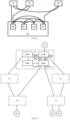
- a dragonfly topology networking consists of multiple Groups (abbreviated as G).
- the dragonfly topology networking includes Group0 (G0), Group 1 (G 1), Group2 (G2), ..., Group8 (G8).
- G0 Group0
- G 1 Group 1
- G2 Group2
- G8 Group8
- all intra-Group and inter-Group network nodes shown in Figure 1 establish a full-mesh connection, meaning that each pair of Groups is connected by means of a link to interconnect network nodes in the pair of Groups, and any network node within each Group is interconnected with other network nodes in the same Group.
- a node designated as an ingress node for a data stream will determine a corresponding multipath group for the data stream.
- the multipath group herein may include the following paths: an optimal path for forwarding the data stream calculated by an optimal path algorithm, as well as loop-free path(s) other than the optimal path (referred to as non-optimal path(s)).
- loop-free path(s) other than the optimal path
- a network node in a same remote Group can be reached through the optimal path and through the loop-free non-optimal paths within the multipath group.
- the remote Group here could be a Group where a network node accessed by a destination of the data stream, such as a host, is located. Therefore, a multipath group of any given data stream corresponds to remote group of the data stream.
- the multipath group of a data stream is described with reference to the dragonfly topology networking as shown in Figure 2 :
- host H1 is connected to a network node (Node1) in Group1 (G 1)
- hosts H2 and H3 are connected to network node(s) in Group3 (G3)
- host H4 is connected to network node(s) in Group4 (G4).
- Node1 in Group 1 (G1) is an ingress node for data streams 1-3 entering the dragonfly topology networking
- Node1 may establish a multipath group for data streams 1-3.
- Node 1 determines that a multipath group for data streams 1-3 includes two following paths: Path 1 (specifically, an optimal path for data streams 1-3) and Path 2 (specifically, a loop-free non-optimal path for data streams 1-3).
- a destination of data streams 1-3 such as host H2 or host H3
- G3 Group3
- G3 Group3
- the remote Group of data streams 1-3 corresponds to the multipath group of data streams 1-3. This ultimately realizes the determination of the multipath group for data streams 1-3.
- destinations of multiple data streams such as the destination IP addresses or IP network segments, are same, these data streams can share a same multipath group.
- each path in the multipath group has a corresponding forwarding weight.
- the forwarding weight of any path indicates a priority of the path for data stream forwarding.
- the forwarding weight of an optimal path is greater than that of a non-optimal path.
- the forwarding weight of any path in the multipath group is determined based on whether the path is an optimal path for forwarding the data stream. Specifically, for any path in the multipath group, if the path is the optimal path for forwarding the data stream, the forwarding weight of the path is determined based on the total number of optimal paths in the multipath group used to forward that data stream. If the path is not the optimal path for forwarding the data stream, the forwarding weight of the path can be directly set to be a preset value, such as 0.
- Path 1 is the optimal path for forwarding data streams 1-3, and there is only one such optimal path of data streams 1-3 (i.e., Path 1), so the weight of Path 1 can be determined as a first value, such as 1.
- the weight of Path 1 can be determined as a second value, such as (1/k).
- Path 2 is not an optimal path for forwarding data streams 1-3, so the forwarding weight of the path can be determined to be a preset value, such as 0.
- Figure 3 illustrates a flowchart of the method provided in the example of the present disclosure.
- This process can be applied to a network node (hereinafter referred to as the first network node for convenience of description) in the aforementioned topology networking.
- the first network node is assumed to be located in the first Group.
- the process can include the following blocks: Block 301: determining, by the first network node as the ingress node for any data stream entering the topology networking, a multipath group for forwarding the data stream.
- the multipath group is specifically described above and will not be repeated here.
- Block 302 receiving, by the first network node, a routing congestion notification sent by a second network node in a same Group through a local first interface.
- each network node in any Group sets congestion detection parameters for its local inter-group interconnection interfaces.
- the local inter-group interconnection interface of a network node in any Group refers to the interface of the network node that locally connects to other Groups.
- Interface 1 of Network Node 2 (abbreviated as Node 2) connects to G3, so Interface 1 of Node 2 is the local inter-group interconnection interface of Node 2.
- the above-mentioned congestion detection parameters may include bandwidth occupancy level and buffer occupancy level, with upper and lower threshold values set respectively (the upper threshold value is greater than the lower threshold value).
- each network node in any Group detects the currently occupied bandwidth level and currently occupied buffer level of each local inter-group interconnection interface respectively, and comprehensively determines whether there is a congestion based on detection results. For example, for each inter-group interconnection interface, if it is detected that at least one of the currently occupied bandwidth level and the currently occupied buffer level of the inter-group interconnection interface is greater than the respective upper threshold value, it is determined that congestion occurs on the inter-group interconnection interface. Conversely, if it is detected that both the currently occupied bandwidth level and the currently occupied buffer level of the inter-group interconnection interface are less than the respective lower threshold value, it is determined that no congestion occurs on the inter-group interconnection interface.
- any network node in any Group detects a congestion on a local inter-group interconnection interface, such as Node 2 detecting a congestion on its local Interface 2 serving as an inter-group interconnection interface as shown in Figure 4
- the network node sends a routing congestion notification (also known as Adaptive Routing Notification, ARN) to other network node(s) in the same Group.
- ARN may carry the information indicating the Group connected by the congested inter-group interconnection interface and congestion parameters.
- Figure 4 shows the forwarding of ARN.
- the ARN sent by any network node in any Group is a User Datagram Protocol (UDP) packet with a destination IP address set to a specified multicast address, such as 224.0.0.2, to ensure that other network node(s) in the same Group receive(s) the ARN. Additionally, an UDP destination port of the ARN is set to a specified port, such as 53344. It can be seen that in this example, the packet format of ARN is simple, facilitating hardware implementation, and only requires a single-hop notification, eliminating the problem of ARN packet reordering. When any network node in any Group detects congestion on a local inter-group interconnection interface, the network node directly sends an ARN without relying on routing protocols, ensuring high real-time performance and efficiency.
- UDP User Datagram Protocol
- the ARN is sent by the second network node upon detecting the congestion on its local second interface; the ARN carries the information indicating the second Group and congestion parameters; the second Group refers to a Group where a peer network node connected by the congested second interface is located, and the second interface is an inter-group interconnection interface connecting the second network node to the second Group, which is different from the first Group.
- the congestion parameters are used to indicate a cause of the congestion on the second interface.
- any network node in any Group such as the aforementioned first network node, receives an ARN
- the network node will execute the description of Block 303 below.
- Block 303 finding, by the first network node, a target multipath group from the multipath groups of data streams, wherein a remote Group associated with the target multipath group is the second Group; and adjusting, based on the congestion parameters, a forwarding weight of a first path with a highest forwarding weight and forwarding weight(s) of other path(s) with lower forwarding weight(s) than that of the first path in the target multipath group; wherein the first path is a path where the first interface is located, an adjusted forwarding weight of the first path is less than that before adjustment, and adjusted forwarding weight(s) of the other path(s) is/are greater than that/those before adjustment, so that a data stream intended to be forwarded through the first path is forwarded through a combination of the first path and the other path(s).
- the forwarding weight of this first path and the forwarding weight(s) of other non-optimal path(s) are dynamically adjusted, so that the data stream intended to be forwarded through the first path is forwarded through a combination of the first path and other path(s), thereby improving link bandwidth utilization.
- the forwarding weight of this first path and the forwarding weight(s) of other non-optimal path(s) are dynamically adjusted, so that the data stream intended to be forwarded through the first path is forwarded through a combination of the first path and other path(s), thereby improving link bandwidth utilization.
- the routing adjustment of the data stream requires the assistance of forwarding entries in specific implementations.
- the ingress node of the data stream after determining the multipath group for any data stream, the ingress node of the data stream generates software forwarding entries corresponding to all paths in the multipath group.
- the software forwarding entry corresponding to each path in the multipath group is associated with the remote Group corresponding to the multipath group.
- the software forwarding entry corresponding to each path in the multipath group is used to describe the forwarding information of that path.
- the forwarding information of each path includes at least: a path identifier and a forwarding weight of the path.
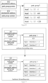
- Figure 5 illustrates an example of the software forwarding entries corresponding to Path 1 and Path 2, respectively, in the multipath group of data streams 1-3.
- the numerical value after ":" in a software forwarding entry corresponding to each path indicates the forwarding weight of the path.
- “:1" indicates the forwarding weight of Path 1 (e.g., that Path 1 carries 100% of the traffic for data streams 1-3).
- “:0" indicates the forwarding weight of Path 2 (e.g., that Path 2 is not used to forward data streams 1-3).
- the ingress node of that data stream may further update these software forwarding entries corresponding to all paths to the hardware, to obtain hardware forwarding entries for the data stream to guide node to forward the data stream.
- the software forwarding entry corresponding to that path may be issued to the hardware to obtain a hardware forwarding entry.
- the forwarding weight of the path is the preset value, which indicates that the path is not used for forwarding, in order to save hardware resources, the issuing of the forwarding entry corresponding to that path to the hardware can be prohibited.
- this example sets the number of hardware forwarding entries for the data stream to a large fixed number L (referred to as the maximum number of entries for the "multipath group"), such as 128. In other words, this example ensures that the number of hardware forwarding entries for the data stream is L.
- the following blocks can be further executed: for each path for which the adjustment is performed in the target multipath group, if the forwarding weight of that path is adjusted from its original preset value to another value, issuing the software forwarding entry corresponding to that path to the hardware to obtain the hardware forwarding entry for that path.
- the forwarding weights of Path 1 and Path 2 in the multipath group for data streams 1-3 are adjusted according to block 303 above, the forwarding weight of Path 2 is no longer the preset value, as shown in Figure 7 .
- the software forwarding entry corresponding to Path 2 can further be issued to the hardware, resulting in a hardware forwarding entry (corresponding to Path 2).
- the final hardware forwarding entries for data streams 1-3 will show 64 hardware forwarding entries for Path 1 and 64 hardware forwarding entries for Path 2, as illustrated in Figure 7 .
- the number of hardware forwarding entries for each path of a data stream may not be equal. For instance, taking L as 128, if there were originally hardware forwarding entries for two paths of data streams 1-3, and after adjusting the forwarding weights the hardware forwarding entries of one path are issued, the number of hardware forwarding entries for these three paths may not be equal when considering the description of L. In such cases, adjustments can be made adaptively. For example, there are 40 hardware forwarding entries for Path 1, 44 hardware forwarding entries for Path 2, and 44 hardware forwarding entries for Path 3, it can be ensured that the total number of hardware forwarding entries for all paths of data streams 1-3 sums up to L, such as 128.
- Block 303 The following is a description of Block 303 mentioned above: Refer to Figure 8 , which shows the implementation flowchart for Block 303 provided in the example of the present disclosure. As shown in Figure 8 , the block can include the following blocks: Block 801: based on the cause of the congestion indicated by the congestion parameters, determining an adjustment coefficient matching the cause of the congestion.
- the congestion parameter(s) can include: a maximum bandwidth set for the second interface, a currently occupied bandwidth of the second interface, a maximum buffer set for the second interface, and/or a currently occupied buffer of the second interface.
- the cause of the congestion is determined to be that the occupied bandwidth of the second interface exceeds the threshold value. In an example, if the currently occupied buffer of the second interface exceeds a buffer threshold value corresponding to the second interface, the cause of the congestion is determined to be that the occupied buffer of the second interface exceeds the threshold value.
- the congestion reason is determined to be that the occupied bandwidth of the second interface exceeds a threshold value and the occupied buffer of the second interface exceeds a threshold value.
- determining the adjustment coefficient matching the cause of the congestions can include:
- Block 802 adjusting the forwarding weights of the first path and other path(s) in the target multipath group based on the adjustment coefficient, and the current occupancy status of the bandwidth of the first interface by the data stream corresponding to the target multipath group and/or the current occupancy status of the buffer of the interface 1 by the data stream corresponding to the target multipath group.
- the ingress node of any data stream maintains an interface status table corresponding to the local interfaces that have enabled the adaptive routing function.
- the interface status table includes the bandwidth occupancy of the interfaces. For example, taking interfaces 1, 2, 3, and 4 of node 1 in Figure 2 as an illustration, the interface status table of Node 1 is shown in Table 1.
- Table 1 interface Bandwidth occupancy, in kbps Buffer occupancy, in bytes interface 1 BW1 BF1 interface2 BW2 BF2 interface3 BW3 BF3 interface4 BW4 BF4
- this example details the occupancy status of the bandwidth and/or buffer of each interface by each multipath group (specifically, by the data stream corresponding to each multipath group).
- Table 2 illustrates the occupancy status of the bandwidth of Interfaces 1 to 4 by various multipath groups: Table 2 Bandwidth occupancy of the interface by the multipath group of data stream 1 Bandwidth occupancy of the interface by the multipath group of data stream n Interface 1 M:a M:c Interface 2 N:b Interface 3 N:d Interface 4
- the above-mentioned block 802 may specifically include: block b1: if the cause of the congestion is that the occupied bandwidth of the second interface exceeds the threshold value, determining a data amount of a data stream corresponding to the target multipath group to be dropped from the first interface based on the currently occupied bandwidth of the first interface by the data stream corresponding to the target multipath group, as well as the adjustment coefficient; selecting a target path from the paths in the target multipath group with forwarding weights lower than that of the first path; wherein the current available bandwidth of the target path supports the said data amount. Then block b4 is performed afterwards.
- the product of the currently occupied bandwidth of the first interface by the target multipath group and the adjustment coefficient can be calculated first. Then, the result of this calculation will be used as the data amount of the data stream corresponding to the target multipath group to be dropped from the first interface.
- the optional ratios for Interface 1 can be set to 60%, 50%, 40%, 30%, 20%), or 10%). These optional ratios are polled in the set order.
- the polled ratio such as 60%
- the product of the specified ratio of the currently occupied bandwidth of the first interface by the target multipath group and the adjustment coefficient is then calculated to get the result.
- whether there is any path with a currently available bandwidth accommodating the specified data amount (i.e., the bandwidth threshold value of the path won't be exceeded after incorporating the data stream) among paths of which each a forwarding weight is lower than that of the first path (including all local interfaces except the first interface) in the target multipath group is checked, whether there is any path with a currently available bandwidth accommodating the specified data amount (i.e., the bandwidth threshold value of the path won't be exceeded after incorporating the data stream) among paths of which each a forwarding weight is lower than that of the first path (including all local interfaces except the first interface) in the target multipath group is checked,.
- Block b2 if the cause of the congestion is that the occupied buffer of the second interface exceeds the threshold value, determining the data amount of the data stream corresponding to the target multipath group to be dropped from the first interface based on the currently occupied buffer of the first interface by the data stream corresponding to the target multipath group, as well as the adjustment coefficient; selecting a target path from the path(s) in the target multipath group with forwarding weight(s) lower than the first path; wherein the current available buffer of the target path should support the aforementioned data amount. Then block b4 is performed.
- This block b2 is similar to the aforementioned block b1 and will not be elaborated further.
- Block B3 if the cause of the congestion is that both the occupied bandwidth of the second interface and the occupied buffer of the second interface exceed their respective threshold values, determining the data amount of the data stream corresponding to the target multipath group to be dropped from the first interface based on the currently occupied bandwidth of the first interface by the data stream corresponding to the target multipath group, the currently occupied buffer of the first interface by the data stream corresponding to the target multipath group, as well as the adjustment coefficient; selecting a target path from the path(s) in the target multipath group with forwarding weight(s) lower than the first path; wherein the currently available buffer and currently available bandwidth of the target path should support the aforementioned data amount. Then block b4 is performed.
- This block b3 is similar to the aforementioned block b1 and will not be elaborated further. It is important to note that there is no fixed chronological order among blocks b 1 to b3.
- Block b4 adjusting the forwarding weight of the first path and the forwarding weight of the target path based on the aforementioned data amount.
- the difference between the currently occupied bandwidth of the first interface by the target multipath group and the occupied bandwidth by the aforementioned data amount is calculated; and the forwarding weights of the first path and the target path based on this difference and the data amount dropped to the target path are adjusted. For instance, if the difference is the same as the occupied bandwidth by the aforementioned data amount, assuming that there are only the first path and the target path in the target multipath group, the weights of the first path and of the target path can be set to be equal, such as both at 50%, to indicate that the first path and the target path will share the forwarding of the data stream subsequently.
- adjustments can be made adaptively, which are not specifically limited in this example.
- Table 4 The occupancy status of each interface in Node 1 by the data stream corresponding to each multipath group is shown in Table 4:: Table 4 Bandwidth occupancy status of interface by multipath group 1 of data stream 1: (multipath group 1 is associated with G3) Bandwidth occupancy status of interface by multipath group 2 of data stream 2: (multipath group 2 is associated with G4) interface 1 M:300 M:300 interface2 N:0 interface3 N:0 interface4
- the ARN sent by Node 2 carries at least the following information: the Group (i.e., G3) where the peer node connected to the congested Interface 1 of Node 2 is located, as well as congestion parameters.
- G3 the Group where the peer node connected to the congested Interface 1 of Node 2 is located
- the congestion parameters can include:
- the congestion parameters indicate that the cause of the congestion is that the occupied bandwidth exceeds the threshold value.
- Node 1 performs a traversal on the optional ratios set for the optimal path (the path containing Interface 1) within the identified Multipath Group 1. Assuming that upon the traversal, the optional ratio of 60% is encountered, Node 1 sets this as the specified ratio, and then multiplies the occupied bandwidth 300kbps of Interface 1 in Table 4 by the specified ratio of 60%, and further multiplies the result by the aforementioned adjustment coefficient of 0.833. This ultimately yields the data amount (150kbps) for Data Stream 1 corresponding to Multipath Group 1 to be dropped from Interface 1. Following this, Node 1 checks whether the currently available bandwidth of the non-optimal path in Multipath Group 1, i.e., the path containing Interface 2, supports this data amount.
- Interface 2's current bandwidth occupancy is 600kbps. Adding the 150kbps, Interface 2's subsequent bandwidth occupancy would be 750kbps, which is below the upper threshold value of bandwidth, which means that Interface 2's currently available bandwidth supports the data amount. Then the path containing Interface 2 is determined as the target path, and the process of selecting the target path ends. If Interface 2's currently available bandwidth does not support the data amount, Node 1 continues to perform a traversal on the optional ratios set for the optimal path in Multipath Group 1, i.e., repeating the block of setting the encountered optional ratio as the specified ratio.
- Interface 1 and Interface 2 each undertake 50% of the data stream corresponding to Multipath Group 1, resulting in a forwarding weight ratio of 1:1 (or 50% each) for Path 1 (containing Interface 1) and Path 2 (containing Interface 2). Since the initial forwarding weight of the Path 2 was set to 0, the software forwarding entry corresponding to the path 2 was not issued to the hardware, as illustrated in Figure 6 . However, after the forwarding weight of the Path 2 is adjusted, which is no longer as 0, as the software forwarding entry illustrated in Figure 7 , the software forwarding entry for Path 2 can be issued to the hardware, resulting in the final hardware forwarding entry shown in Figure 7 .
- Node 2 once Node 2 detects that the state of Interface 1 has shifted from congestion to be normal, the following recovery operations may be performed: restoring the forwarding weights of paths, which were adjusted due to the congestion, back to their respective original unadjusted values. Additionally, the current hardware forwarding entries may be updated to those hardware forwarding entries before the congestion. Of course, in other examples, Node 2 detects that the state of Interface 1 has shifted from congestion to be normal, the aforementioned recovery operations may not to be performed to save resources.
- FIG. 9 it is a diagram of the structure of the apparatus provided in an example of the present disclosure.
- the apparatus is applied to a first network node in a topology networking.
- the topology networking consists of multiple node groups (Groups), and any two network nodes within the same Group are interconnected, and network nodes in different Groups are also interconnected.
- the first network node is located in the first Group.
- the apparatus includes:
- the forwarding weight of any non-optimal path is initially a preset value
- the ARN is a UDP packet
- the destination IP of the ARN is a specified multicast address, which is used to control all network nodes in the first Group other than the second network node to receive the ARN.
- the block of adjusting, based on the congestion parameters, the forwarding weight of the first path with the highest forwarding weight and the forwarding weight(s) of the other path(s) with the lower forwarding weight(s) than the first path in the target multipath group includes: based on the cause of the congestion indicated by the congestion parameters, determining an adjustment coefficient matching the cause of the congestion; adjusting the forwarding weights of the first path and other path(s) in the target multipath group based on the adjustment coefficient, the occupancy status of the bandwidth of the first interface by the data stream corresponding to the target multipath group, and/or the occupancy status of the buffer of the first interface by the data stream corresponding to the target multipath group.
- the congestion parameters include: the currently occupied bandwidth of the second interface, and the currently occupied buffer of the second interface; wherein, if the currently occupied bandwidth of the second interface exceeds the bandwidth threshold value corresponding to the second interface, the cause of the congestion is determined to be that the occupied bandwidth of the second interface exceeds the threshold value; if the currently occupied buffer of the second interface exceeds the buffer threshold value corresponding to the second interface, the cause of the congestion is determined to be that the occupied buffer of the second interface exceeds the threshold value; if both the currently occupied bandwidth of the second interface exceeds the bandwidth threshold value corresponding to the second interface and the currently occupied buffer of the second interface exceeds the buffer threshold value corresponding to the second interface, the cause of the congestion is determined to be that both the occupied bandwidth of the second interface exceeds a threshold value and the occupied buffer of the second interface exceeds a threshold value.
- the congestion parameters further include: the maximum bandwidth set for the second interface, and the maximum buffer set for the second interface; wherein
- the block of adjusting the forwarding weights of the first path and other path(s) in the target multipath group based on the adjustment coefficient, the current occupancy status of the bandwidth of the first interface by the data stream corresponding to the target multipath group, and/or the current occupancy status of the buffer of the first interface by the data stream corresponding to the target multipath group includes:
- the apparatus examples described above are merely illustrative, and the modules described as separate components may or may not be physically separated.
- the components shown as modules may or may not be physical modules, i.e., they can be located in one place or distributed across multiple network modules. Depending on actual needs, some or all of the modules can be selected to achieve the objectives of this specification. Ordinary technicians in the field can understand and implement them without creative effort.
- an example of the present disclosure also shows a hardware structure diagram of the apparatus shown in Figure 9 .
- the electronic device can be a device implementing the aforementioned methods.
- the hardware structure includes:
- the aforementioned machine-readable storage medium can be any electronic, magnetic, optical, or other physical storage device capable of containing or storing information such as executable instructions, data, etc.
- the machine-readable storage medium can be RAM (Random Access Memory), volatile memory, non-volatile memory, flash memory, storage drives (such as hard disk drives), solid-state drives, any type of storage disk (such as optical disks, DVDs, etc.), or similar storage media, or combinations thereof.
Landscapes
- Engineering & Computer Science (AREA)
- Computer Networks & Wireless Communication (AREA)
- Signal Processing (AREA)
- Data Exchanges In Wide-Area Networks (AREA)
Applications Claiming Priority (1)
| Application Number | Priority Date | Filing Date | Title |
|---|---|---|---|
| CN202311272277.5A CN117081984B (zh) | 2023-09-27 | 2023-09-27 | 一种路由调整方法、装置及电子设备 |
Publications (1)
| Publication Number | Publication Date |
|---|---|
| EP4531367A1 true EP4531367A1 (de) | 2025-04-02 |
Family
ID=88717227
Family Applications (1)
| Application Number | Title | Priority Date | Filing Date |
|---|---|---|---|
| EP24199094.4A Pending EP4531367A1 (de) | 2023-09-27 | 2024-09-06 | Routinganpassungsverfahren, -vorrichtung und elektronische vorrichtung |
Country Status (3)
| Country | Link |
|---|---|
| US (1) | US20250106145A1 (de) |
| EP (1) | EP4531367A1 (de) |
| CN (1) | CN117081984B (de) |
Families Citing this family (3)
| Publication number | Priority date | Publication date | Assignee | Title |
|---|---|---|---|---|
| CN119211108B (zh) * | 2024-09-29 | 2026-02-24 | 新华三技术有限公司 | 一种表项更新方法、装置、电子设备及存储介质 |
| CN119766720A (zh) * | 2024-12-27 | 2025-04-04 | 新华三技术有限公司 | 流量转发方法、装置、设备、存储介质及计算机程序产品 |
| CN120075116A (zh) * | 2025-02-21 | 2025-05-30 | 中国银联股份有限公司 | 一种转发路径调整方法及装置 |
Citations (2)
| Publication number | Priority date | Publication date | Assignee | Title |
|---|---|---|---|---|
| US9282037B2 (en) * | 2010-11-05 | 2016-03-08 | Intel Corporation | Table-driven routing in a dragonfly processor interconnect network |
| EP3979598A1 (de) * | 2020-09-30 | 2022-04-06 | Juniper Networks, Inc. | Bandbreitenbeschränkung für mehrpfadsegmentrouting |
Family Cites Families (10)
| Publication number | Priority date | Publication date | Assignee | Title |
|---|---|---|---|---|
| US6831895B1 (en) * | 1999-05-19 | 2004-12-14 | Lucent Technologies Inc. | Methods and devices for relieving congestion in hop-by-hop routed packet networks |
| US9379981B1 (en) * | 2013-09-27 | 2016-06-28 | Google Inc. | Flow level dynamic load balancing |
| CN107770083B (zh) * | 2016-08-16 | 2021-04-20 | 华为技术有限公司 | 一种交换网络、控制器及负载均衡方法 |
| CN112152933B (zh) * | 2019-06-27 | 2023-03-10 | 华为技术有限公司 | 一种发送流量的方法和装置 |
| CN110365588B (zh) * | 2019-07-16 | 2021-11-09 | 新华三技术有限公司合肥分公司 | 数据流调度方法、装置及sdn控制器 |
| CN110708242B (zh) * | 2019-10-28 | 2021-12-17 | 迈普通信技术股份有限公司 | 流量调度方法、装置、电子设备及存储介质 |
| CN111711565B (zh) * | 2020-07-01 | 2021-05-04 | 西安电子科技大学 | 面向高速互连蜻蜓+网络的多路径路由方法 |
| CN115733799B (zh) * | 2021-08-25 | 2025-06-13 | 超聚变数字技术有限公司 | 网络拥塞控制方法及相关装置 |
| CN115914078A (zh) * | 2021-09-28 | 2023-04-04 | 华为技术有限公司 | 报文转发方法及装置、蜻蜓网络 |
| CN113992539B (zh) * | 2021-10-28 | 2023-03-24 | 中国人民解放军战略支援部队信息工程大学 | 网络安全动态路由跳变方法及系统 |
-
2023
- 2023-09-27 CN CN202311272277.5A patent/CN117081984B/zh active Active
-
2024
- 2024-09-06 US US18/827,100 patent/US20250106145A1/en active Pending
- 2024-09-06 EP EP24199094.4A patent/EP4531367A1/de active Pending
Patent Citations (2)
| Publication number | Priority date | Publication date | Assignee | Title |
|---|---|---|---|---|
| US9282037B2 (en) * | 2010-11-05 | 2016-03-08 | Intel Corporation | Table-driven routing in a dragonfly processor interconnect network |
| EP3979598A1 (de) * | 2020-09-30 | 2022-04-06 | Juniper Networks, Inc. | Bandbreitenbeschränkung für mehrpfadsegmentrouting |
Also Published As
| Publication number | Publication date |
|---|---|
| CN117081984B (zh) | 2024-03-26 |
| US20250106145A1 (en) | 2025-03-27 |
| CN117081984A (zh) | 2023-11-17 |
Similar Documents
| Publication | Publication Date | Title |
|---|---|---|
| EP4531367A1 (de) | Routinganpassungsverfahren, -vorrichtung und elektronische vorrichtung | |
| US10097469B2 (en) | Network traffic shaping for low power and lossy networks | |
| US10938724B2 (en) | Flow rate based network load balancing | |
| US9270598B1 (en) | Congestion control using congestion prefix information in a named data networking environment | |
| JP5722455B2 (ja) | ネットワークにおけるメッセージおよび計算オーバーヘッドの軽減 | |
| US8755390B2 (en) | Network data congestion management method | |
| US9015299B1 (en) | Link grouping for route optimization | |
| CN107634912B (zh) | 负载均衡方法、装置及设备 | |
| EP2911348B1 (de) | Steuerungsvorrichtungsentdeckung in Netzwerken mit separaten Steuerungs- und Weiterleitungsvorrichtungen | |
| US20160149816A1 (en) | Fault Tolerant and Load Balanced Routing | |
| US20120201241A1 (en) | Method & apparatus for the distribution of network traffic | |
| EP2845347A1 (de) | Überlaststeuerung in einem paketdatennetzwerk | |
| IL230202A (en) | Method and apparatus for resilient routing of control traffic in a split-architecture system | |
| WO2013150438A1 (en) | Congestion control and resource allocation in split architecture networks | |
| WO2023050874A1 (zh) | 报文转发方法及装置、蜻蜓网络 | |
| US20120155268A1 (en) | Packet relay device | |
| CN116827856A (zh) | 一种链路路径切换方法、装置 | |
| WO2025252048A1 (zh) | 信息处理方法、装置、设备、可读存储介质及程序产品 | |
| CN114793215A (zh) | 一种基于负载均衡模式异步代理的分布式系统 | |
| EP4622210A1 (de) | Verfahren und vorrichtung zur wartung von routinginformationen sowie netzwerkvorrichtung und speichermedium | |
| Siddiqi et al. | Improving network convergence time and network stability of an OSPF-routed IP network | |
| US11502941B2 (en) | Techniques for routing data in a network | |
| EP1721414A1 (de) | Netzwerkarchitektur | |
| CN118353831A (zh) | 交换机节点确定方法、装置及相关设备 | |
| CN119402416B (zh) | 通信方法及装置 |
Legal Events
| Date | Code | Title | Description |
|---|---|---|---|
| PUAI | Public reference made under article 153(3) epc to a published international application that has entered the european phase |
Free format text: ORIGINAL CODE: 0009012 |
|
| STAA | Information on the status of an ep patent application or granted ep patent |
Free format text: STATUS: REQUEST FOR EXAMINATION WAS MADE |
|
| 17P | Request for examination filed |
Effective date: 20240909 |
|
| AK | Designated contracting states |
Kind code of ref document: A1 Designated state(s): AL AT BE BG CH CY CZ DE DK EE ES FI FR GB GR HR HU IE IS IT LI LT LU LV MC ME MK MT NL NO PL PT RO RS SE SI SK SM TR |